SuperBlade Server SBS-820H-420P. USER’S MANUAL (Revision 1.0) - page 2
Chapter 3: Installation and Setup
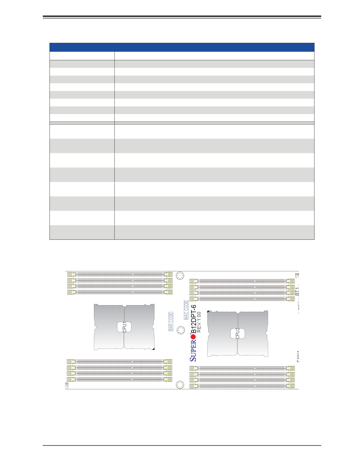
Memory Population for the X12 DP Motherboard, 16 DIMM Slots
CPUs/DIMMs
Memory Population Sequence
1 CPU & 1 DIMM
A1
1 CPU & 2 DIMMs
A1, E1
1 CPU & 3 DIMMs*
A1, C1, E1
1 CPU & 4 DIMMs
A1, C1, E1, G1
1 CPU & 5 DIMMs*
A1, B1, C1, E1, G1
1 CPU & 6 DIMM
A1, B1, C1, E1, F1, G1
1 CPU & 7 DIMMs*
A1, B1, C1, D1, E1, F1, G1
1 CPU & 8 DIMMs
A1, B1, C1, D1, E1, F1, G1, H1
CPU1: A1
2 CPUs & 2 DIMMs
CPU2: A1
CPU1: A1, E1
2 CPUs & 4 DIMMs
CPU2: A1, E1
CPU1: A1, B1, E1, F1
2 CPUs & 6 DIMMs*
CPU2: A1, E1
CPU1: A1, B1, E1, F1
2 CPUs & 8 DIMMs
CPU2: A1, B1, E1, F1
CPU1: A1, B1, C1. E1, F1, G1
2 CPUs & 10 DIMMs*
CPU2: A1, B1, E1, F1
CPU1: A1, B1, C1. E1, F1, G1
2 CPUs & 12 DIMMs
CPU2: A1, B1, C1. E1, F1, G1
CPU1: A1, B1, C1. D1, E1, F1, G1, H1
2 CPUs & 14 DIMMs*
CPU2: A1, B1, C1. E1, F1, G1
CPU1: A1, B1, C1. D1, E1, F1, G1, H1
2 CPUs & 16 DIMMs
CPU2: A1, B1, C1. D1, E1, F1, G1, H1
*Unbalanced, not recommended.
HDD
P1-DIMMF1
P1-DIMME1
P1-DIMMH1
P2-DIMMB1
P1-DIMMG1
P2-DIMMA1
P2-DIMMD1
P2-DIMMC1
Rear
Front
P1-DIMMC1
P1-DIMMD1
P2-DIMMG1
P1-DIMMA1
P2-DIMMH1
P1-DIMMB1
P2-DIMME1
P2-DIMMF1
A1
Figure 3-3. Memory Slots
40
Chapter 3: Installation and Setup
Installing Memory
ESD Precautions
Electrostatic Discharge (ESD) can damage electronic components including memory modules.
To avoid damaging DIMM modules, it is important to handle them carefully. The following
measures are generally sufficient.
• Use a grounded wrist strap designed to prevent static discharge.
• Handle the memory module by its edges only.
• Put the memory modules into the antistatic bags when not in use.
Installing Memory
Begin by removing power from the system as described in Section 3.1. Follow the memory
population sequence in the table above.
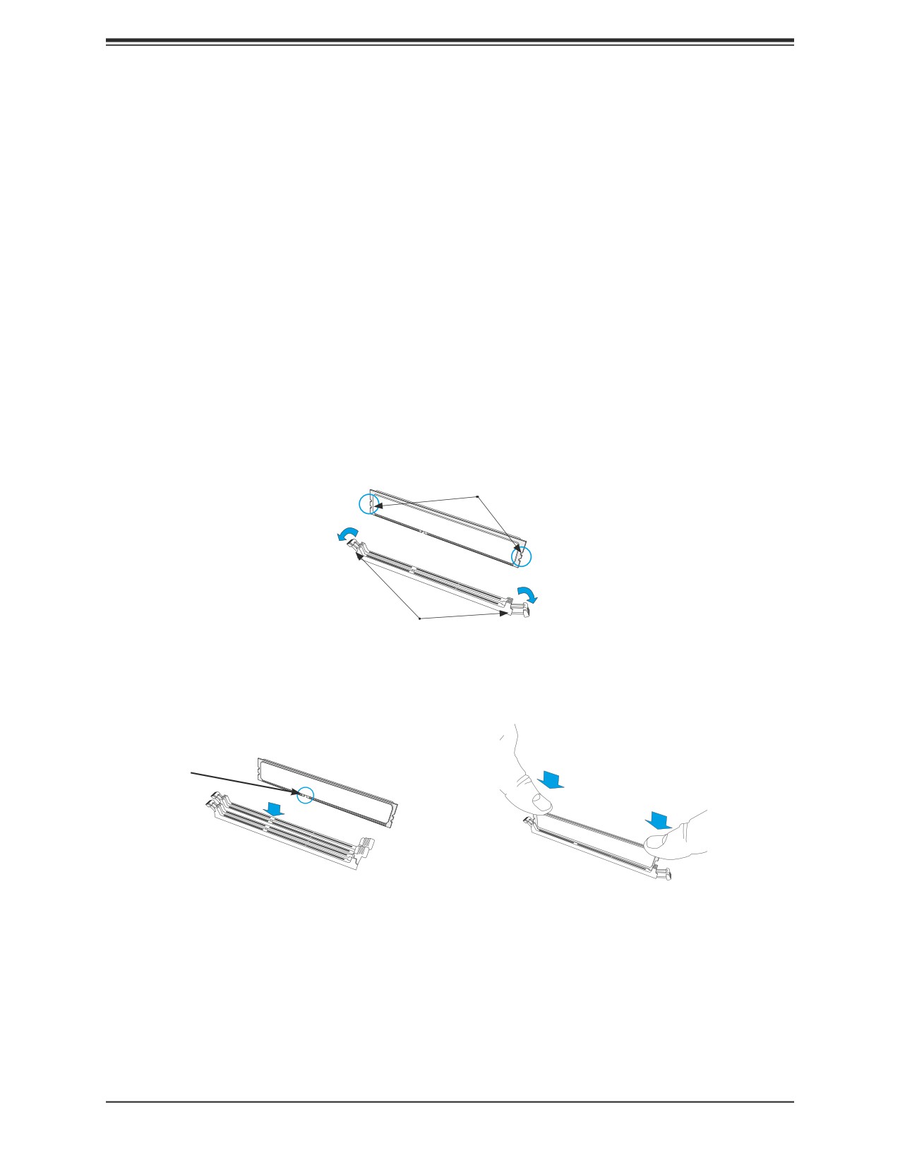
1. Push the release tabs outwards on both ends of the DIMM slot to unlock it.
Notches
Release Tabs
2. Align the key of the DIMM with the receptive point on the memory slot and with your
thumbs on both ends of the module, press it straight down into the slot until the module
snaps into place.
Key
3. Press the release tabs to the locked position to secure the DIMM module into the slot.
Caution: Exercise extreme caution when installing or removing memory modules to prevent
damage to the DIMMs or slots.
Removing Memory
To remove a DIMM, unlock the release tabs then pull the DIMM from the memory slot.
41
Chapter 3: Installation and Setup
3.8 Motherboard Battery
The motherboard uses non-volatile memory to retain system information when system power
is removed. This memory is powered by a lithium battery residing on the motherboard.
Replacing the Battery
When the blade has been removed from the enclosure.
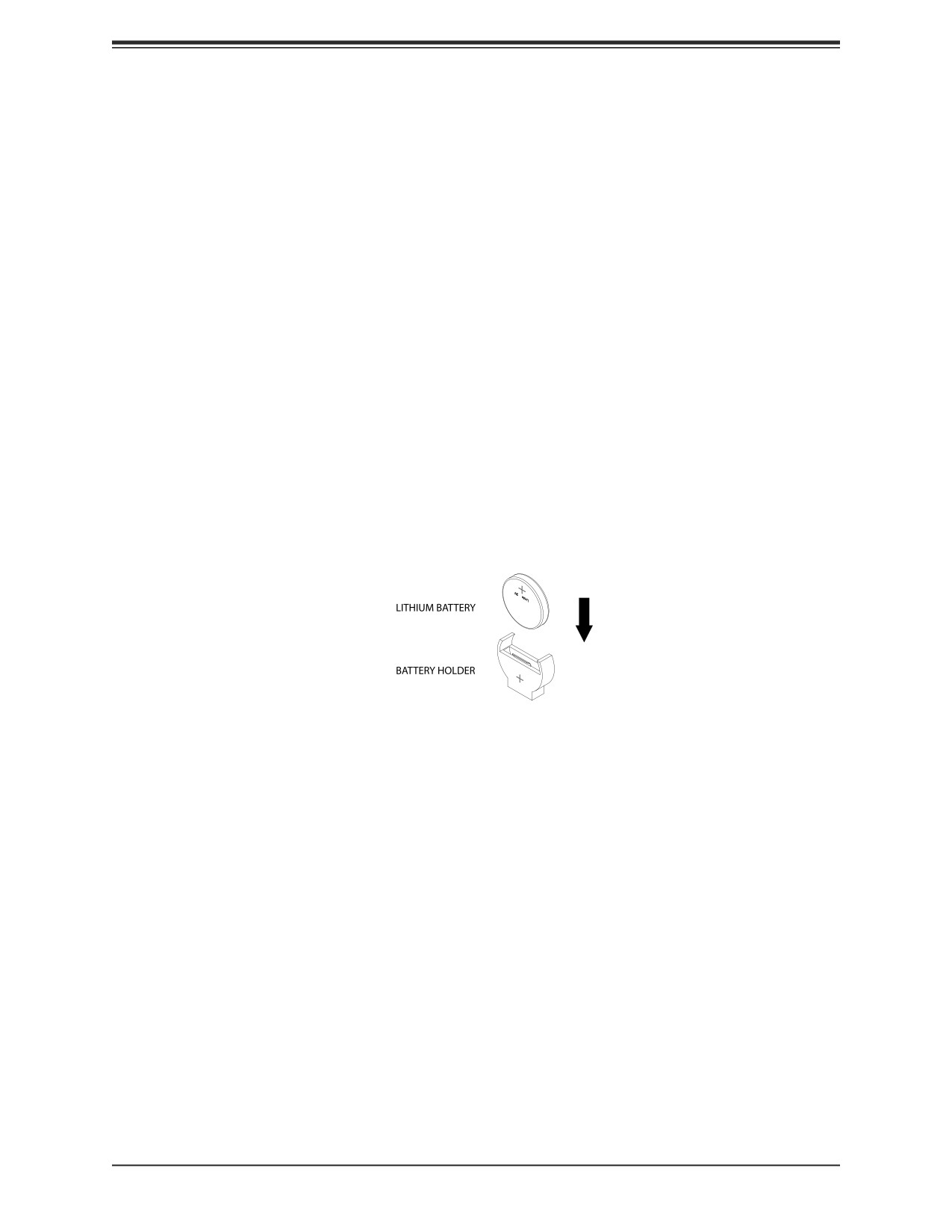
1. Push aside the small clamp that covers the edge of the battery. When the battery is
released, lift it out of the holder.
2. To insert a new battery, slide one edge under the lip of the holder with the positive (+)
side facing up. Then push the other side down until the clamp snaps over it.
Note: Handle used batteries carefully. Do not damage the battery in any way; a damaged
battery may release hazardous materials into the environment. Do not discard a used battery
in the garbage or a public landfill. Please comply with the regulations set up by your local
hazardous waste management agency to dispose of your used battery properly.
OR
Figure 3-4. Installing the Onboard Battery
Warning: There is a danger of explosion if the onboard battery is installed upside down (which
reverses its polarities). This battery must be replaced only with the same or an equivalent type
recommended by the manufacturer (CR2032).
42
Chapter 3: Installation and Setup
3.9 Storage Drives
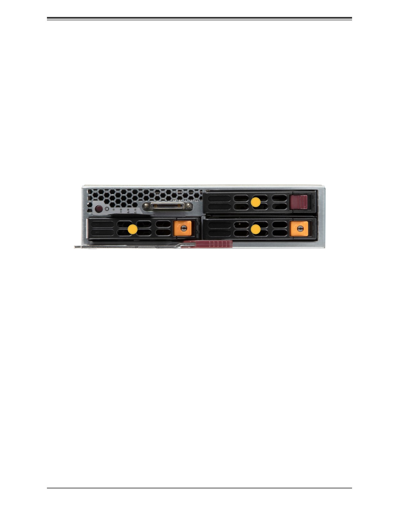
The blade has three 2.5" hot-swap storage drive bays. The drives are mounted in tool-less
drive carriers that simplify their removal from the chassis. These carriers also help promote
proper airflow. Carriers without drives must remain in the chassis for proper airflow.
For VROC configurations, refer to the VROC section in this manual.
Note: Enterprise level storage drives are recommended for use in Supermicro systems. For
information on recommended drives, visit the Supermicro website.
Installing Drives
2
0
1
Figure 3-5. Logical Drive Numbers
43
Chapter 3: Installation and Setup
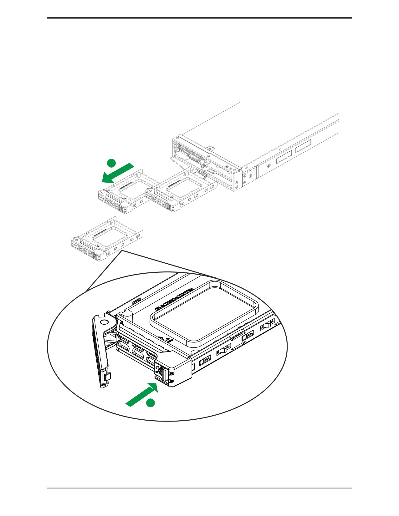
Removing a Hot-Swap Drive Carrier from the Chassis
1. Press the release button on the drive carrier, which will extend the drive carrier handle.
2. Use the drive carrier handle to pull the drive out of the chassis.
2
1
Figure 3-6. Removing a Drive Carrier
44
Chapter 3: Installation and Setup
Installing a Drive
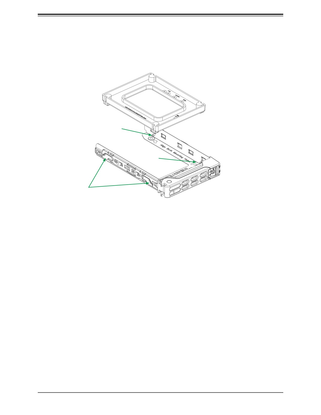
1. Remove the dummy drive, which comes pre-installed in the drive carrier. Pull out the two
spring locking clasps and lift out the dummy drive.
Post
Post
Locking Clasps
Figure 3-7. Removing the Dummy Drive from a Carrier
2. Position the drive into the carrier with the PCB side facing down and the connector end
toward the rear of the carrier.
3. Tilt the drive to insert it onto the two posts on the right inside of the carrier.
4. Pull out the two spring locking clasps to allow the drive to sit fully in the carrier, then
release them to secure the drive.
5. Insert the drive carrier into its bay, keeping the release button on the bottom. When the
carrier reaches the rear of the bay, the release handle will retract.
6. Push the handle in until it clicks into its locked position
45
Chapter 3: Installation and Setup
Hot-Swap for NVMe Drives
Supermicro servers support NVMe surprise hot-swap. For even better data security, NVMe
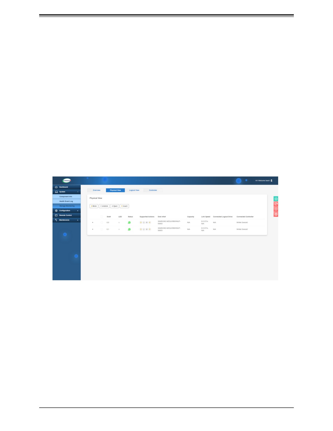
orderly hot-swap is recommended. NVMe drives can be ejected and replaced remotely using
the BMC Dashboard.
Ejecting a Drive
1. BMC Dashboard > Server Health > NVMe SSD
2. Select Device, Group and Slot, and click Eject. After ejecting, the drive Status LED
indicator turns green.
3. Remove the drive.
Note that Device and Group are categorized by the CPLD design architecture.
Slot is the slot number on which the NVMe drives are mounted.
Figure 3-8. BMC Dashboard Screenshot
Replacing the Drive
1. Insert the replacement drive.
2. BMC Dashboard > Server Health > NVMe SSD
3. Select Device, Group and slot and click Insert. The drive Status LED indicator flashes
red, then turns off. The Activity LED turns blue.
46
Chapter 3: Installation and Setup
Checking the Temperature of an NVMe Drive
There are two ways to check using the BMC Dashboard.
Checking a Drive
• BMC Dashboard > Server Health > NVMe SSD - Shows the temperatures of all NVMe
drives.
• BMC Dashboard > Server Health > Sensor Reading > NVME_SSD - Shows the single
highest temperature among all the NVMe drives.
M.2 Storage
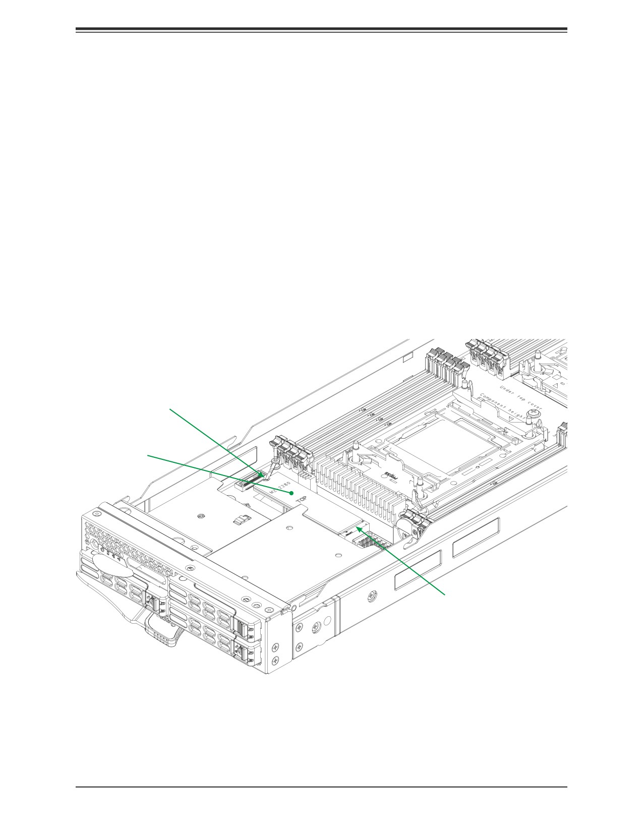
The system supports one M.2 solid state drive of form factor 2280.
• Insert the M.2 card into the M.2 slot, then secure it with the plastic pin at the other end.
Plastic Plug
M.2 SSD
M.2 Slot
Figure 3-9. Installing M.2 SSD
47
Chapter 3: Installation and Setup
3.10 Cooling
Fans, Enclosure
Power supply modules include a system fan. If a power supply fails, its fan will continue to
operate to provide continuous cooling. For this reason, a failed power supply should remain
installed in the enclosure until a replacement unit is ready.
Auxiliary Fans
Three optional fan modules (PWS-DF005-2F) with two fans each are available for extra
cooling. They may be required for configurations such CPUs with TDP over 155W.
48
Chapter 3: Installation and Setup
Air Shrouds, Blade
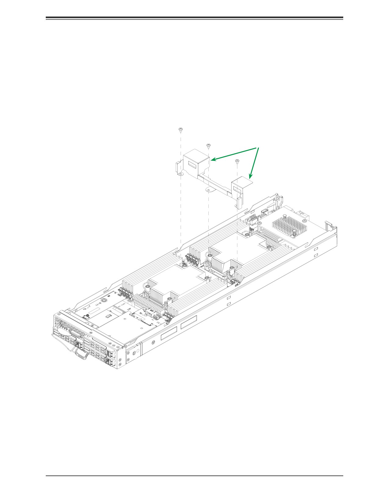
Air shrouds concentrate airflow to maximize fan efficiency.
Installing the Air Shrouds
• Position the air shrouds as illustrated in the figure below, sliding them over the components,
and secure them with screws. The screws are shared with the motherboard.
Air Shrouds
Figure 3-10. Installing the Air Shrouds
49
Chapter 3: Installation and Setup
Checking the Server Air Flow
• Make sure there are no objects to obstruct airflow in and out of the server.
• Do not operate the server without drives or drive carriers in the drive bays.
• Use only recommended parts.
• Make sure no wires or foreign objects obstruct air flow through the server. Pull all excess
cabling out of the airflow path or use shorter cables.
Overheating
For overheating problems, check that:
• There are no obstructions, such as poorly routed cables.
• All fans are operating normally.
• The ambient room temperature is not too warm (refer to Appendix B, Environmental Speci-
fications).
There are several possible responses if the system overheats.
• Use the LEDs to determine the nature of the overheating condition.
• Confirm that the chassis covers are installed properly.
• Make sure all fans are present and operating normally.
• Check the routing of the cables.
• Verify that the heatsinks are installed properly.
Also, either of the blade management software utilities can increase the fan speed and
maximize system cooling.
50
Chapter 3: Installation and Setup
3.11 Installing Components
Install:
• Power Supply Modules
• Fans
• CMM (see also Chapter 5)
• Switches or pass-thru modules
• Blade servers
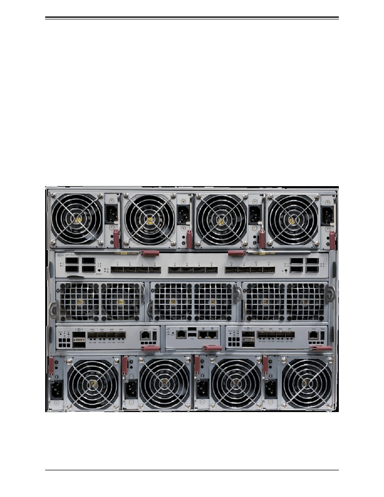
In all cases, pull out the locking lever(s), slide the component into the enclosure, then secure
with the locking lever.
Note: All module bays must be populated either with a module or a dummy module cover to
maintain proper airflow.
Figure 3-11. Rear Modules Installed
51
Chapter 4: Power Supplies and Fans
Chapter 4
Power
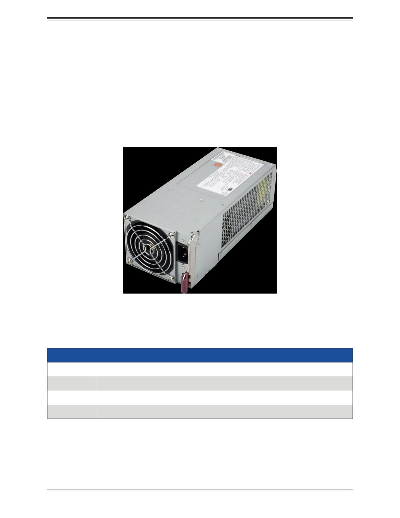
The SuperBlade enclosure integrates a power supply and a cooling fan into a single module.
The fan can operate independently from the power supply, so that if the power supply fails,
the fan continues to provide cooling for the system. The Chassis Management Module (CMM)
monitors the status of the power supplies and the power information for the enclosure.
Figure 4-1. Example Power and Fan Module, PWS-2K21A-BR
4.1 Module Description
An LED status indicator is located near the locking lever.
Status Indictor
Color
Description
Red
Power module failure
Amber
Possible module failure or the AC power cord unplugged
Green
Module operating normally
Power Cord
A plastic locking clip partially covering the socket was designed to prevent the power supply
module from being removed with the power cord still connected.
Only the recommended power cord or an equivalent 14 gauge cord should be used. Typical
C13/C14 cords are only 16 Gauge wiring and pose a fire hazard if substituted.
52
Chapter 4: Power Supplies and Fans
For details on the required power cord for your country, see the Supermicro website at:
4.2 Installing a Power Supply
To prevent compatibility issues, only use components that match the specifications or part
numbers.
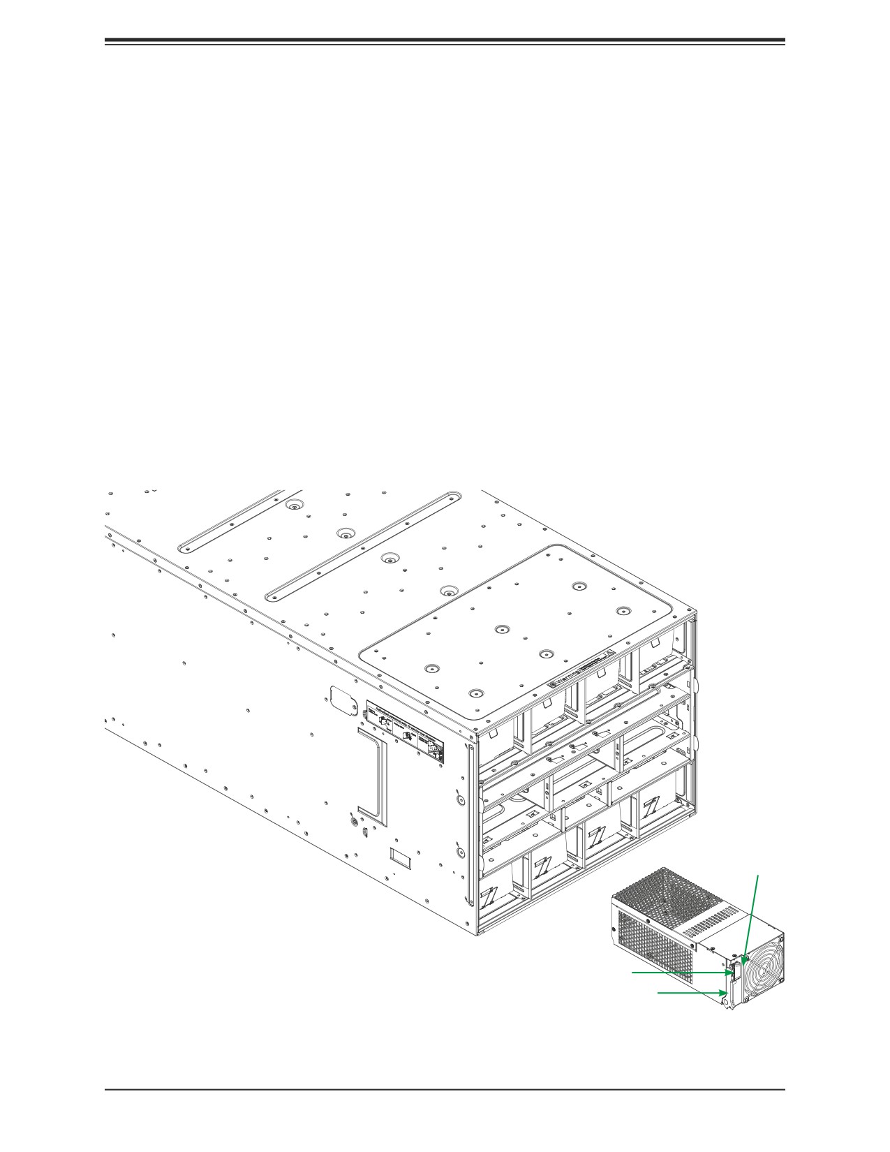
1. Insert the power module into the empty power bay. Be sure that the orientation is
correct. Match the pictures of the chassis front in Chapter 1. If you inadvertently put a
power supply upside down, it can be very difficult to remove.
2. Push unit all the way in until it is firmly seated.
3. Push the locking handle into the closed position until it clicks into position.
4. Move the locking clip away from the socket and reconnect the power cord.
LED Indicator
Locking Lever
Locking Clip
Figure 4-2. Installing a Power Supply Module
53
Chapter 4: Power Supplies and Fans
Removing a Power Supply
1. Remove the power cord from the power supply unit.
2. Release the locking clip to unlock the power supply module.
3. Pull out the locking handle and remove the unit. To release the handle, squeeze the two
metal plates of the handle with your thumb and fingers, and then pull the module out.
4.3 Power Supply Failure
If a power module or a fan in a power module fails, the system management software will
provide an alert. Replace the power module with another identical one. Note that if a power
supply fails, its fans will continue to operate. For this reason, a failed power supply should
remain installed in the enclosure until a replacement unit is ready.
Redundant Power Supplies
Each blade enclosure can hold multiple power supplies. Installing all possible power supplies
may provide you with redundant power, depending upon the number of blades in the
enclosure, the model and power level of the power supplies installed and the power load
from modules in your system. The configuration for power redundancy is created using the
IPMIView application tool for the system.
For purposes of denoting the amount of redundancy, a server system has N main power
supplies to support the whole system. N+n denotes "n" the number of redundant power
supplies. For example, N+1 describes a system with one power supply for redundancy.
For example, suppose a 10-blade system has four 2000 Watt power supply units (PSU), for
a total power supply of 8000 Watts. The maximum power usage of each blade is 375 Watts
for a total power demand of 3750 Watts to run the whole system. So in this example there
are effectively two redundant power supplies (N+2) over what is needed to power the blades
in the system.
• If one or two PSU fail, then 6000W or 4000W, respectively, are available. The CMM will
detect the remaining power left for the whole system. And because the total blade power
usage is only 3750 Watts, every blade can still work properly.
• If three PSUs fail, then the remaining 2000 Watts available cannot support the whole sys-
tem. Therefore the CMM will start to shut down or throttle down the load in order to keep
blades running based upon the priority settings that were made for each blade using the
IPMIView application until the load is enough to power the remaining blade modules.
In the IPMIView tool you can set the priority (default CPU power usage) of each blade first
before any PSU fails (0%->shut down, 50%->throttling, 100%->Running).
54
Chapter 4: Power Supplies and Fans
4.4 Power Management
The Chassis Management Module assumes the maximum power case for each blade prior to
applying power. If the system power is not sufficient, the CMM will not allow that unit to power
up. After a blade is powered up, the blade BIOS calculates the actual power load required by
that blade based upon the installed devices and informs the CMM of its requirements. The
CMM then recalculates the remaining power for additional blades.
Backup Battery Power
Backup battery power (BBP) modules, like all rechargeable batteries, eventually their capacity
and performance decline as they age. Regular maintenance of charge and discharge cycles
is recommended to maintain the effectiveness of the BBP batteries. At least one charge and
discharge cycle for every 30 days is recommended. The BBP maintenance scheduler can be
enabled and configured through the CMM.
When the BBP function is disabled through the CMM, the battery will discharge until the
minimum energy state is reached. While the battery function is disabled, regular BBP
maintenance cannot be performed since the battery energy remains at the lowest state and
will not re-charge. As a result, the battery capacity and performance will decline at a faster
pace, and/or cause the battery to no longer operate. The battery will remain the minimum
charge until the BBP function is again re-enabled through CMM. The user should use the
disabling BBP function with caution knowing that the possible outcome of degraded battery
performance or not operational battery.
The discharge duration can be extended by adding additional BPP modules.
55

Chapter 4: Power Supplies and Fans
4.5 Power Supply Specifications
PWS-2K21A-BR
Feature
Description
Maximum Output
2200W
Type
Hot-swap Redundant Module (N+1)
Dimensions (WxLxH)
106.5 x 245.3 x 84 mm
100-127Vac input: 100A
200-220Vac input: 150A
Input Rated Voltage/
220-230Vac input: 165A
Current
230-240Vac Input: 174A
200-240Vac Input: 183.3A (UL/cUL Only)
Rated Frequency
50-60HZ
UL & cUL (North America):
200-220V: 2090W
220-240V: 2200W
Rest of the world:
Maximum Power
100-127V: 1200W
200-220V: 1800W
220-230V: 1980W
230-240V: 2090W
Efficiency Certification
80Plus Platinum, 96%
+12V Output
1200/1800/1980/2090/2200: 100A/150A/165A/174A/183.3A
+12Vsb DC Output
2A
Operating Temp: 0° to 50° C (up to 5000m)
Operating Conditions
Non-operating Temp: -40° to 75° (up to 15200m)
Humidity (Non-Condensing): 80% Operating, 95% Non-operating
56
Chapter 5: Chassis Management Module
Chapter 5
Chassis Management Module
The Chassis Management Module (CMM) is a "command” module that communicates with
the blade units, the power supplies and the blade switches. Used in conjunction with the Web
Interface or IPMI View management software, the CMM provides administrator control over
individual blade units, power supplies, cooling fans and networking switches and monitors
onboard temperatures, power status, voltage levels and fan speeds. It is a required module
in a blade system.
5.1 Features
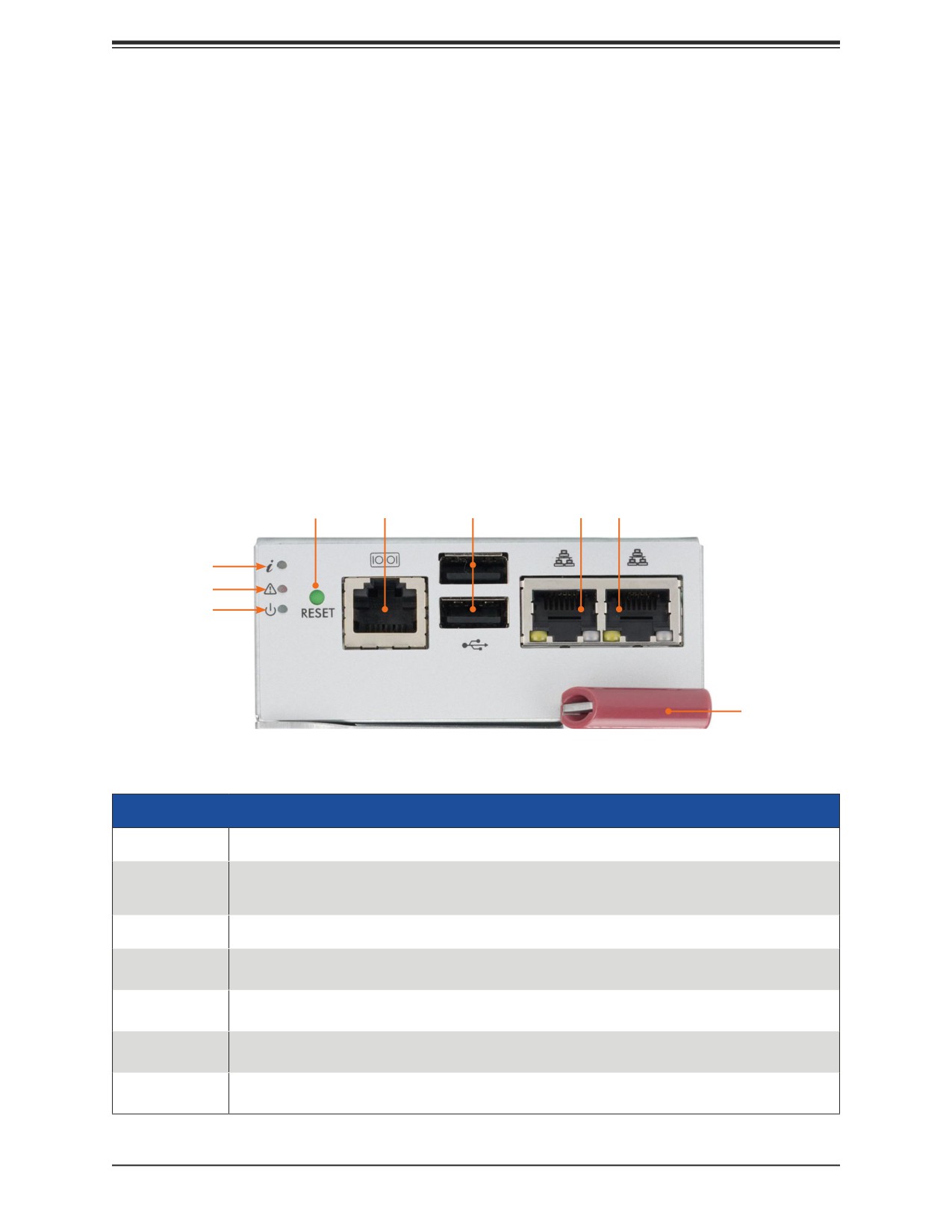
Reset
BMC Port
USB Ports
Ethernet Ports
Info LED
Fault LED
Power LED
Locking Lever
Figure 5-1. MBM-CMM-FIO Module Interface
MBM-CMM-FIO
Feature
Description
Management
Can manage up to 28 blade units, network modules and eight power supplies
Capabilities
Ports
Two Ethernet ports, one BMC dedicated LAN and two USB ports (for debug only)
Basic Functions
Remote KVM, remote storage, Serial-over-LAN (SOL), blade monitoring and control, switch,
Supported
PWS, monitor, thermal, redundancy in some enclosure models
System
System management interface provided via dedicated LAN, switch, PWS, monitor, thermal,
Management
and redundancy in some enclosure models
Power
Approximately 20W
Consumption
Operating
Firmware (upgradeable)
System
57

Chapter 5: Chassis Management Module
LED Status Indicators
LED
Color, Status
Description
Power
Green
Power on
Fault
Red
Fatal error, including power supply or thermal
Blue, solid
UID activated
Information
Blue, blinking faster than 1Hz
Firmware updating
Blue, blinking 1Hz
Indicator for active Master CMM
Capabilities
The CMM provides a dedicated, local and remote KVM (keyboard/video/mouse) connection
over an out of band TCP/IP Ethernet network during any server state (functioning, blue-screen,
powered down, BIOS and so on). It also supports Virtual Media (VM) redirection for CD, floppy
and USB mass storage devices and configures such information as the switch IP addresses.
Module Redundancy
A blade system must have one CMM and may have two for redundancy is offered only on
a specific enclosure model, which has the hardware capability to incorporate two CMM's on
one backplane. Since the CMM uses its own processor, all monitoring and control functions
are carried out regardless of the operation or power status of the blade units. CMM modules
can only be installed in the upper and/or lower right module bays.
Determining Master/Slave Modules Status
When a blade system has two CMM modules, they are assigned a master/slave status. This
is done automatically with the default primary CMM specified for per each enclosure, while
there will be no redundant in certain enclosures.
If the master CMM is powered down or removed (or is being reset by its user), the second
(slave) CMM module will then immediately be assigned as the master. The redundant CMM
mode is only offered on specific chassis models. The slave uses the previous master IP
config in case of failover.
Note: The Slave CMM keeps the same log/status as the Master CMM and uses the previous
master IP config.
58
Chapter 5: Chassis Management Module
5.2 Installation
Use this procedure to install the CMM module to the SuperBlade enclosure. Make sure the
cover to the module has been installed before proceeding. Follow the anti-static precautions.
Installing the Module
1. Remove the dummy cover from the bay in which you want to place the module.
2. Place the module locking lever in the open position.
3. Slide the module into the module bay until it stops.
4. Push the locking lever to the closed position.
After the module has been installed and the handle locked, it will turn on and a POST test
will run to verify it is working properly.
Removing the Module:
1. Pull out the release handle to the open position.
2. Pull the module out of the bay.
3. Replace immediately with another module or with a dummy module cover to maintain
airflow integrity.
5.3 Configuring the CMM
To access and configure the CMM, first configure the IP settings of the CMM depending on you
network environment. The below procedure for this configuration just serves as a reference
for getting the CMM setup. If your system has Linux OS, please follow similar instructions to
get the CMM setup.
The CMM access topology is as follows:
DHCP Access: Connect a network cable to the CMM module.
• The system should boot into the default Fail Over mode. The DHCP mode will appear on
the CLI mode screen.
• If the system failover and CLI is not active, it will proceed to the default IP access.
• If the CMM cannot enter the default IP, then an RJ45/USB cable can be connected from
the CMM RJ45 Ethernet LAN Port to the Desktop Host using the USB Port in Serial Port
mode with a speed set at 115200. The DHCP IP can be manually set at the same subnet-
mask for gateway access at 192.168.100.100.01.
Default IP Access:
The requirements are a computer with an RJ45 port and an ethernet cable.
59
Chapter 5: Chassis Management Module
1. Connect network cable to the network port at CMM. The default IP of the CMM is
2. Configure the connected computer to the same address range, such as
https://192.168.100.101. The default mode is the Fail Over mode. If the DHCP fails, then
the CMM will automatically default to the IP address of the CMM.
Configuring the CMM in Windows OS:
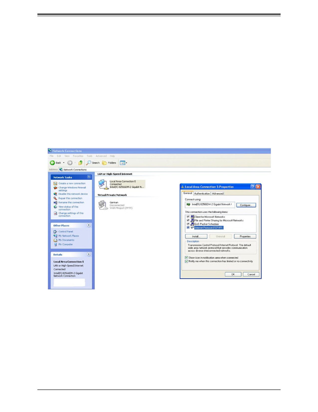
1. Go to Start > Control Panel > Network Connections.
2. Right-click on LAN to View Properties.
3. On the General tab page, choose “Internet Protocol (TCP/IP)” and click Properties.
Figure 5-3. Configuring CMM, Choose Protocol
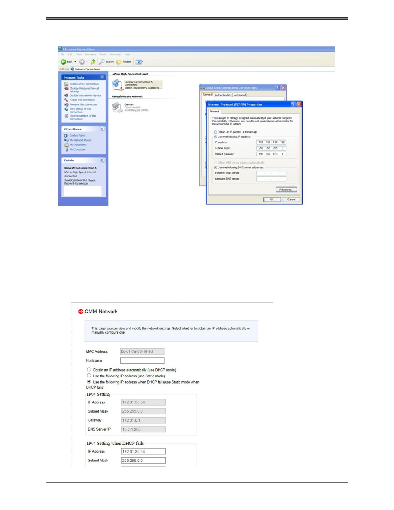
4. Manually configure the IP address of the computer system to be in the same address
range as the CMM (see Figure 5-4).
Example:
IP address: https://192.168.100.101
Subnet Mask: 255.255.255.0
Default Gateway: 192.168.100.1
60
Chapter 5: Chassis Management Module
Figure 5-4. Configuring CMM, Choose Protocol
Once the IP address for the computer system is configured, the CMM can be accessed
through the web browser by entering the default IP address 192.168.100.100 of the CMM
into the browser’s address bar.
Now, the IP address, subnet mask and default gateway of the CMM can be changed according
to the network environment. Refer to the Web-based Management Utility User’s Manual for
more information.
Figure 5-5. Configuring CMM, Changing Settings
61
Chapter 5: Chassis Management Module
Caution: Do not change any other setting, unless you are familiar with it.
Note: The above screens are examples for purposes of demonstrating this procedure. The
screens you actually view may or may not appear the same as those shown above.
5.4 CMM Functions
The following sections describe local functions and remote functions of the CMM. With only
minor exceptions, all of the remote functions can be performed by one of three mechanisms:
web-based access to the CMM module, access to the CMM using IPMIview, a client tool
implemented in Java, or via IPMItool commands (DOS commands or shell scripted commands).
When the web-based browser is used, the CMM acts as a web server, requiring a higher
bandwidth connection to the CMM. If there are any bandwidth constraints, IPMI will provide
a superior experience. Additionally, since graphical updates are provided by client-side Java,
IPMIview can also be a superior user experience.
IPMItool, on the other hand, can provide the ability to issue similar or identical commands to
many SuperBlade enclosures/CMM to manage all of them in a similar way.
Remote KVM over IP
Remote KVM over IP is independent from local KVM (although local KVM can operate in
parallel with Remote KVM). Remote KVM encrypts all communication between the remote
user and the CMM.
To Use: Remote KVM over IP is initiated with the management software (IPMI View or Web-
based utility). Attach the LAN cable to the LAN port on the CMM module then refer to "Web-
based Management Utility" on page 4-13 to login and use either utility.
Remote Storage (Virtual Media)
The Remote Storage function allows the user to connect to a remote storage device (such
as a floppy, hard disk, or USB storage device) and access the device as if it were local. This
can be used not only to read and write to remote storage devices but to load an operating
system from a remote drive.
Serial Over LAN (SOL)
Serial Over LAN allows you to redirect the input and output of a serial port via IPMI in order
to manage blade modules from a remote location.
To Use: Serial Over LAN can be activated via the Web-based Management utility. See the
Web-based Management Utility User’s Manual for the procedure to initiate SOL.
62
Chapter 5: Chassis Management Module
Monitoring Functions
Used in conjunction with IPMI or the Web-based Management utility, the CMM module can
monitor and provide information on the hardware health of the blade modules and the system
as a whole. In addition to the monitoring functions, you can remotely power on, power off or
reboot a system.
Health information includes:
• Temperature levels
• Fan speeds
• Voltage levels
• Power status
Power Consumption Management
The CMM module firmware can also control all power on/off activity in the whole blade
system. This is done by using the Power button, onboard BMC or from any other use of
remote management software.
Once a blade module is installed in the enclosure the installed CMM immediately receives
information on the rated Max Power Consumption value of the new blade module. The CMM
then calculates whether there is enough power for this new blade module by comparing
the Max Power Consumption value of the new blade module with the calculated Remaining
Power value of the system.
If there is enough power, the CMM will power on the blade. However if there is not enough
power in the blade system, then the new blade module is not powered on and the front panel
LED on the enclosure will blink.
After the blade is powered on, the CMM then collects the actual power consumption of this
individual blade and updates the calculated Remaining Power value for the system.
The CMM also reserves power for all the networking and chassis management modules
installed on the system.
Caution: One CMM module must be running to control the power systems and prevent
overloading.
5.5 USB Ports and Reset Button
The USB ports only used for debugging purposes and not for communication with your system.
Reset Button returns address settings to their defaults.
IP Address
Reset to https://192.168.100.100
Gateway Address
Reset to 0.0.0.0
Subnet Mask Reset to 255.255.255.0
63
Chapter 5: Chassis Management Module
5.6 Firmware
The firmware for the CMM switch resides in the module. This firmware can be updated with
the web-based management utility.
Within the utility, go to the Maintenance > Update Firmware screen. Here you can enter the
name of the firmware you want to update or click Browse to select the firmware file. Finish
by clicking the Upload button.
Note: This process is not reversible once the firmware is updated, so proceed with caution.
It might take a few minutes to complete this procedure.
5.7 Web-based Management Utility
System management may be performed with either of three software packages: IPMIview,
SMCIPMItool or a Web-based Management Utility. Any of these utilities are designed to
provide an administrator with a comprehensive set of functions and monitored data to keep
tabs on the system and perform management activities.
The Web-based Management Utility is a web-based interface that consolidates and simplifies
system management for Supermicro SuperBlade systems. The Web-based Management
Utility aggregates and displays data from the CMM module.
The Web-based Management Utility provides the following key management features:
• Enables IT administrators to view in-depth hardware configuration and status information
using a single intuitive interface.
• Provides an OS-independent, remote graphical console.
• Allows remote users to map local media (floppy, removable disks and hard drives) or ISO
images on a shared network drive to a blade server.
Supported Browsers
The following browsers have been tested for use with the Web-based Management Utility. It is
recommended that you use the most current revision of the browser you choose. The minimum
browser revisions supported by the Web-based Management Utility are shown below:
Internet Explorer 7
Firefox 2.0.0.7
Netscape 9.03b
Network Connection/Login
To log into the Web-based Management Utility:
1. Launch a web browser.
64
Chapter 5: Chassis Management Module
2. In the address field of the browser, enter the IP address that you assigned to the system
and hit the <Enter> key.
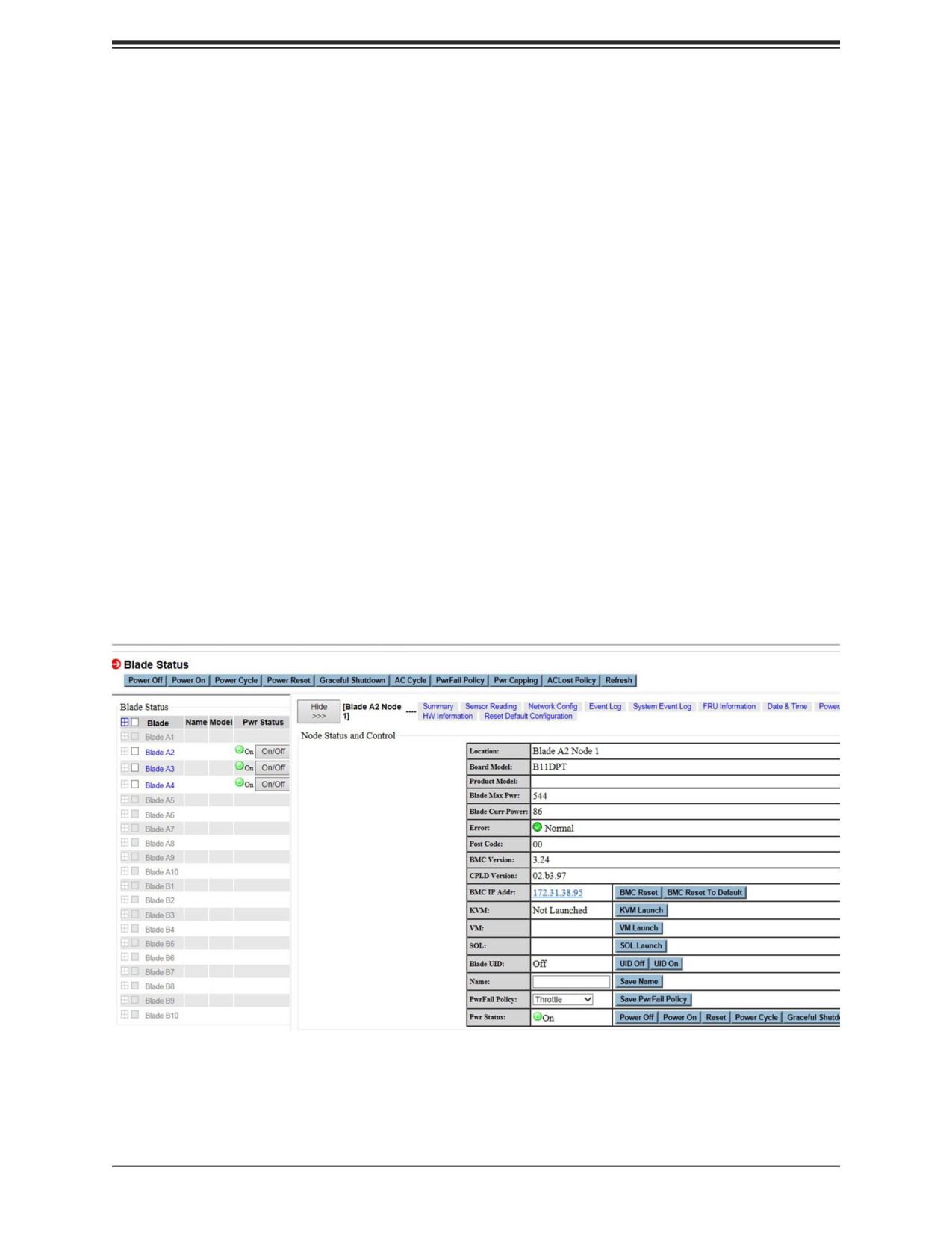
3. When the browser makes contact with the CMM, enter your user name and password,
then click Login. The Web-based Management Utility Home Page will then display as
shown below.
Note: Supermicro ships standard products with a unique password for the BMC ADMIN user.
This password can be found on a label on the motherboard. For more information, please refer
Address Defaults
The CMM default addresses are:
IP Address - Reset to https://192.168.100.100
Gateway Address - Reset to 0.0.0.0
Subnet Mask - Reset to 255.255.255.0
The address can be changed using the Web-based Management Utility.
Home Page
Figure 5-6. Configuring CMM, Web-based Utility
For more information on the Web-based Management Utility, and a description of its controls,
see the Web-based Management Utility User’s Manual.
65
Chapter 6: 200G Switch
Chapter 6
SuperBlade HDR 200G InfiniBand Blade Switch
6.1 Overview
The document provides the details about the SuperBlade HDR 200G InfiniBand Blade Switch
model SBM-IBS-H4020.
Supermicro SBM-IBS-H4020 is an HDR 200G InfiniBand Blade Switch designed for
Supermicro blade enclosures for high performance datacenter traffic applications. It provides
a 1:1 non-blocking architecture and supports twenty internal HDR ports at 200G and twenty
external HDR ports at 200G with ZQSFP+/QSFP56 ports.
Module Managment
The switch is unmanaged. It does not use an operating system.
66
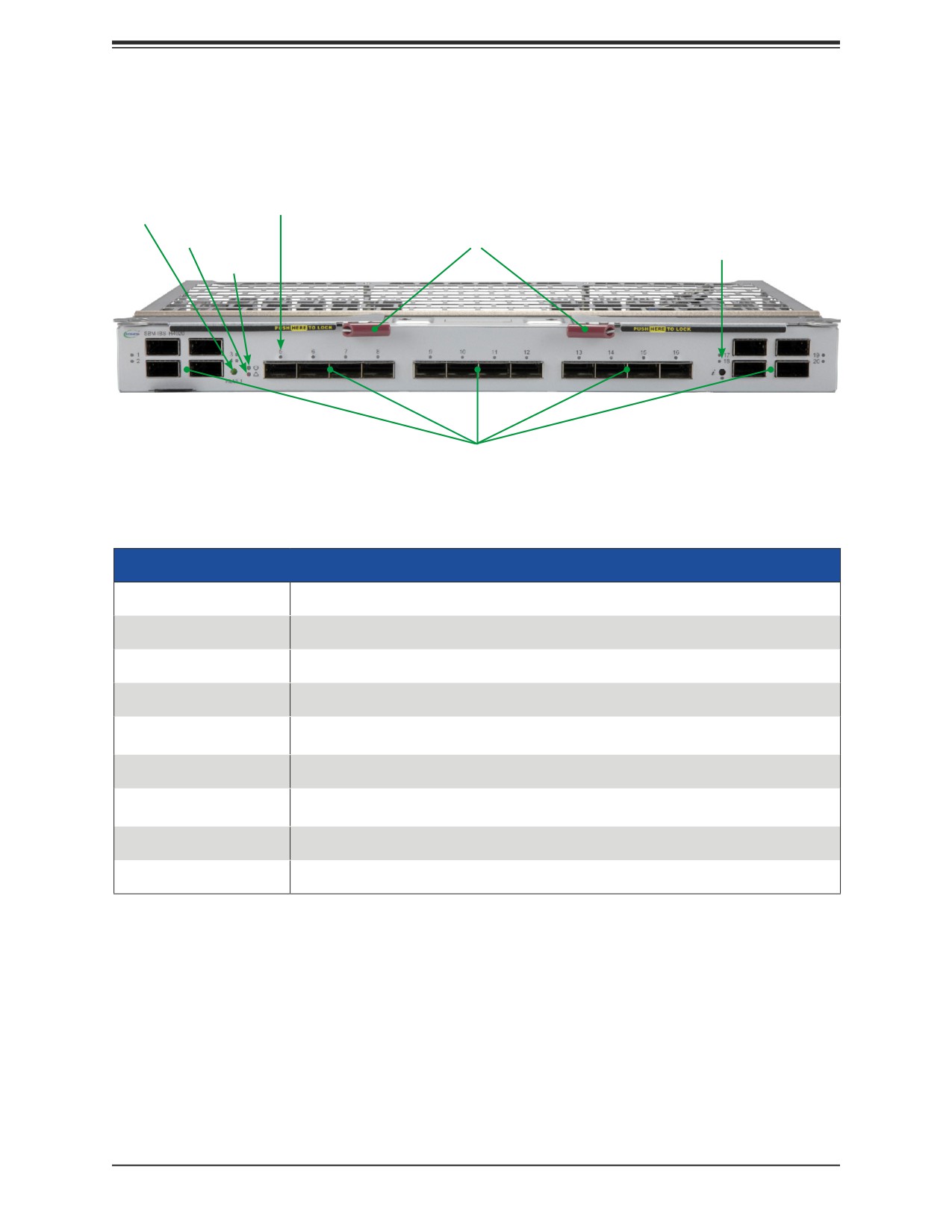
Chapter 6: 200G Switch
6.2 Features
The switch module includes these features.
Port LED
Reset Button
Fault LED
Latch Lever
UID Button
Initiation
and LED
OK LED
ZQSFP+/QSFP56
Ports
Figure 1. Front View
Front Features
Feature
Description
ZQSFP+/QSFP56 Ports
Ports accept QSFP56 Direct Attach Cable (DAC) or QSFP56 transceiver modules
Port LED
Each port has a status LED that indicates a port linkup
Reset Button
Reset the switch
Indicates module has either failed POST or has detected an operational fault within
Fault LED
the module
Initiation OK
Indicates module is operational and has passed the POST with no critical fault
Module has either failed POST or has detected an operational fault within the
Module Fault LED
module
Latch Levers
Used to physically install or uninstall the module
UID Button and LED
Unit ID LED indicator can be activated using the button or the CMM interface
67
Chapter 6: 200G Switch
6.3 Installation
Make sure the cover to the switch module has been installed before installation.
1. Pull open the latch levers of the blade switch module.
2. Slide the switch module into the bay until the module connectors seat in the enclosure.
3. Push the latch levers closed.
The module will power on and a POST test will verify it is working properly.
Removing the Blade Switch
The switch module is hot-swappable. The blade enclosure and blades can continue to operate
when it is removed.
• Pull open the latch levers and pull the module out of the enclosure.
68
Chapter 6: 200G Switch
6.4 Specifications
Hardware Specifications
• Internal Ports: Twenty HDR 200G Ports
• External Ports: Twenty HDR 200G Ports with ZQSFP+/QSFP56 connectors
Physical & Environmental Specifications
• Weight:
8.927 LB
• Dimensions:
6 &1/2” x 10 &9/16” x 1 &1/2”
• Temperature: Operating 0°C to 45°C (32°F to 113°F)
• Humidity: Operating 5% to 95% (non-condensing)
Power Specifications
• Hot-Pluggable: Yes
• Power consumption (Typical): 244 Watts
Enclosure Compatibility
• This blade switch module is compatible with the Supermicro enclosure SBE-820H with no
more than one switch module per enclosure.
69
Chapter 6: 200G Switch
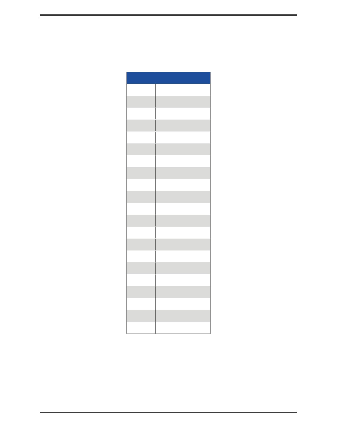
6.5 Port Mapping
The port mapping between the blade servers and the switch internal ports is shown in the
table below.
Port Mapping
Module
Internal Port
A1
P21
A2
P22
A3
P23
A4
P24
A5
P25
A6
P26
A7
P27
A8
P28
A9
P29
A10
P30
B1
P31
B2
P32
B3
P33
B4
P34
B5
P35
B6
P36
B7
P37
B8
P38
B9
P39
B10
P40
70
Chapter 6: 200G Switch
6.6 Cabling and Transceiver Compatibility
The SBM-IBS-H4020 has been qualified with the following cables for compatibility:
Passive:
• CBL-NTWK-0643—INFINIBAND, QSFP56, 200G, PASSIVE, PULL, 2M, 26AWG
• CBL-MCP7H50-H002R26—INFINIBAND, QSFP56,HDR 200G to 2x100G, 2M, 26AWG
Active:
• CBL-MFS1S00H10-MT037—INFINIBAND, QSFP56, 200G, ACTIVE OPTICAL 10M
• CBL-QSFP56AOC-20M—INFINIBAND, QSFP56, 200G, ACTIVE OPTICAL 20M
Transceiver:
• MMA1T00-HS Optical Transceiver HDR QSFP56 MPO 850nm SR4 up to 100m
71
Chapter 7: Motherboard Connections
Chapter 7
Motherboard Connections
This chapter describes the connections on the motherboard and provides pinout definitions.
Note that depending on how the system is configured, not all connections are required. The
LEDs on the motherboard are also described here. A motherboard layout indicating component
locations may be found in Chapter 1. More detail can be found in the Motherboard Manual
Please review the Safety Precautions in Appendix A before installing or removing components.
7.1 Power Connections
Main Power Connector
The proprietary main power header is PWR1.
Storage Drive Power Connectors
The proprietary 4-pin connector, HDD2_PWR, is connected to the AOM-SB1-SATA31 to
provide power to the HDD2.
7.2 Headers and Connectors
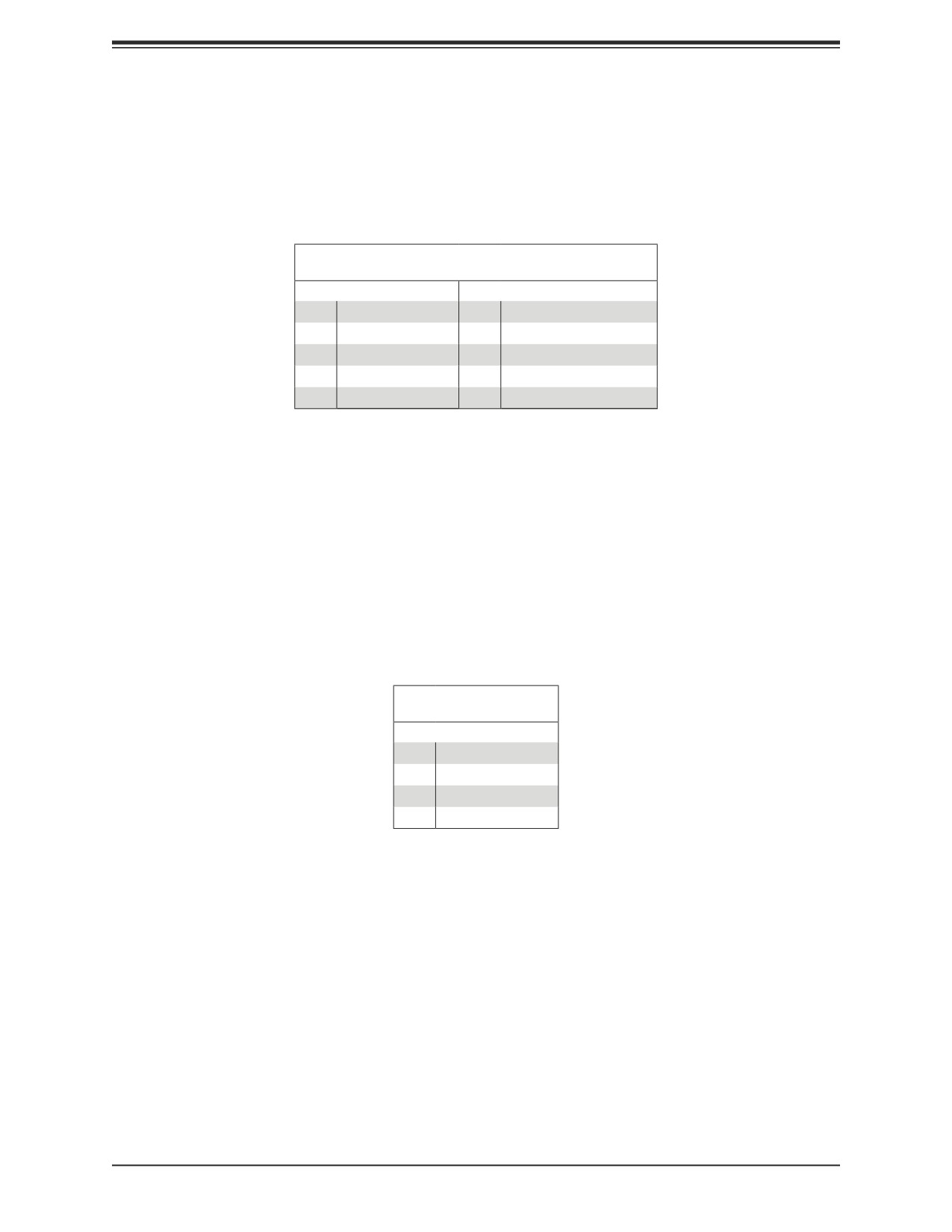
Fan Header
A 4-pin fan header (FAN1) is located on the motherboard. This fan header is reserved for
liquid cooling.
Fan Header
Pin Definitions
Pin# Definition
1
Ground (Black)
2
+12V (Red)
3
Tachometer
4
PWM Control
72
Chapter 7: Motherboard Connections
TPM Header
The JTPM1 header is used to connect a Trusted Platform Module (TPM), which is available
from Supermicro. A TPM connector is a security device that supports encryption and
authentication in hard drives. It allows the motherboard to deny access if the TPM associated
with the storage drive is not installed in the system.
Trusted Platform Module Header
Pin Definitions
Pin# Definition
Pin# Definition
1
P3V3
2
SPI_TPM_CS_N
3
PCI-E_RESET_N#
4
SPI_PCH_MISO
5
SPI_PCH_CLK#
6
Ground
7
SPI_PCH_MOSI
8
N/A
9
JTPM1_P3V3A
10
IRQ_TPM_SPIN_N
M.2 Slot
The M2-1 connector is an M.2 slot for SSD storage. It is PCIe 4.0 x4 SSD in the 2280 form
factor with support of M-Key 2280.
RAID Key Header
A VROC RAID Key header is located at JRK1. It supports VMD used in creating optional
advanced NVMe RAID configurations. See the VROC section for details.
RAID Key Header
Pin Definitions
Pin# Definition
1
Ground
2
3.3V Standby
3
Ground
4
PCH_RAID_KEY
I-SATA 3.0 Port (for SBI-420P-1T3N)
The motherboard has one SATA 3.0 port (I-SATA1), which is supported by the Intel C621A
PCH. Connect this port to the AOM-SB1-SATA31 add-on module.
HDD2 SATA Activity LED Connector (for SBI-420P-1T3N)
JLED is a 3-pin connector used to indicate the status of HDD2 SATA Activity. Connect JLED
to the AOM-SB1-SATA31 add-on module to show HDD2 SATA activity.
73
Chapter 7: Motherboard Connections
7.3 Jumpers
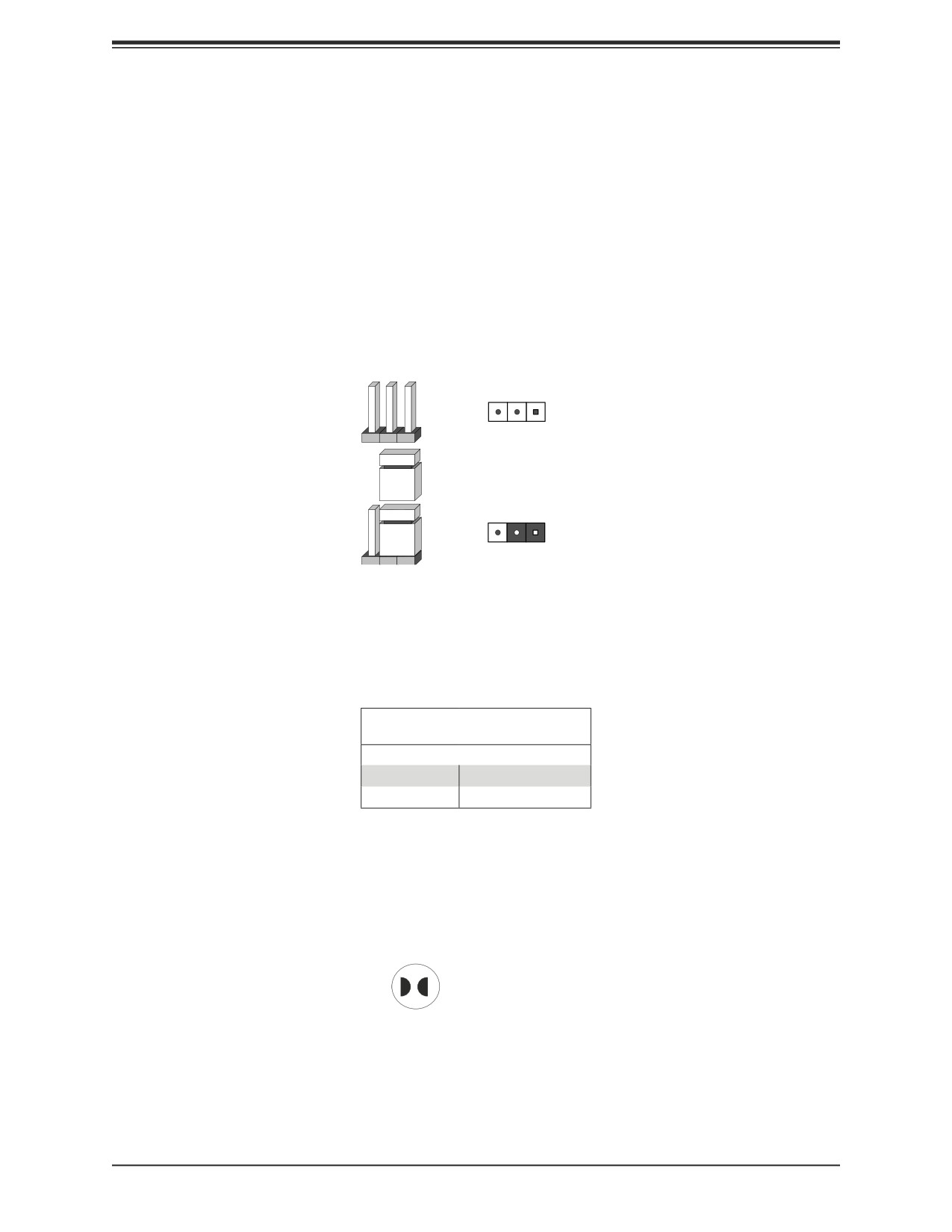
Explanation of Jumpers
To modify the operation of the motherboard, jumpers are used to choose between optional
settings. Jumpers create shorts between two pins to change the function associated with it.
Pin 1 is identified with a square solder pad on the printed circuit board. See the motherboard
layout page for jumper locations.
Note: On a two-pin jumper, "Closed" means the jumper is on both pins and "Open" indicates
the jumper is either on only one pin or has been completely removed.
3
2
1
Connector
Pins
Jumper
3
2
1
Setting
ME Recovery
JPME1 is used for ME Firmware Recovery mode, which will limit system resource for essential
function use only without putting restrictions on power use. In the single operation mode,
online upgrade will be available in Recovery mode.
ME Recovery
Jumper Settings
Jumper Setting Definition
Pins 1-2
Normal (Default)
Pins 2-3
ME Recovery
CMOS Clear Contacts
JBT1 is used to clear CMOS. Instead of pins, this jumper consists of contact pads. See
Chapter 10 for more information.
JBT1 contact pads
74
Chapter 7: Motherboard Connections
7.4 LED Indicators
BMC Heartbeat LED
LEDM1 is a BMC Heartbeat indicator. It blinks green when the BMC is working properly.
M.2 Activity LED
LED1 is an M.2 Activity indicator. When it is blinking green, M.2 is active.
75
Chapter 8: Blade Software
Chapter 8
Blade Software
After the hardware has been installed, you can install the Operating System (OS), configure
RAID settings and install the drivers.
8.1 Installing the Operating System
An operating system (OS) must be installed on each blade module. Blades with Microsoft
Windows OS and blades with Linux OS can operate within the same blade enclosure. Refer
to the SuperMicro website for a list of supported operating systems.
Installing by using PXE Boot
Preboot Execution Environment (PXE) is used to boot a computer over a network. To install
the OS using PXE, the following conditions must be met:
• The PXE BOOT option in BIOS must be enabled.
• A PXE server has been configured; this can be another blade in the system.
• The PXE server must be connected over a network to the blade switch to be booted.
• The blade has only non-partitioned/unformatted hard drives installed and no bootable
devices attached to it.
Once these conditions are met, make sure the PXE server is running. Then turn on the blade
on which you wish to install the OS. The BIOS in the blade will look at all bootable devices
and finding none, will connect to the PXE server to begin the boot/install.
Installing by using Virtual Media (Drive Redirection)
You can install the OS via Virtual Media through either the IPMIview (Java-based client utility),
SuperBladeTool or the Web-based Management Utility. With this method, the OS is installed
from an ISO image that resides on another system.
Refer to the manuals on the SuperMicro website for further details on the Virtual Media (CD-
ROM or Drive Redirection) sections of these two utility programs.
Linux Installation with Two Storage Drives—Note
When installing Linux with three storage drives you may encounter a situation where one
drive is recognized as HDA and the other drive is recognized as SDA. This is normal since
in this case the connection for SATA HDDs is from two different controllers.
76
Chapter 8: Blade Software
Under Native IDE mode (which is the default), your Linux OS will see one drive as HDA and
the other as SDA. If the SATA controller mode operation is changed to AMD_AHCI in the
BIOS, then the HDDs will appear as SDA and SDB.
Microsoft Windows OS Installation
If you will be using RAID, you must configure RAID settings before installing the Windows
OS and the RAID driver. Refer to the RAID Configuration User Guides posted on our website
at www.supermicro.com/support/manuals.
Installing the OS
1. Create a method to access the MS Windows installation ISO file. That might be a DVD,
perhaps using an external USB/SATA DVD drive, or a USB flash drive, or the BMC KVM
console.
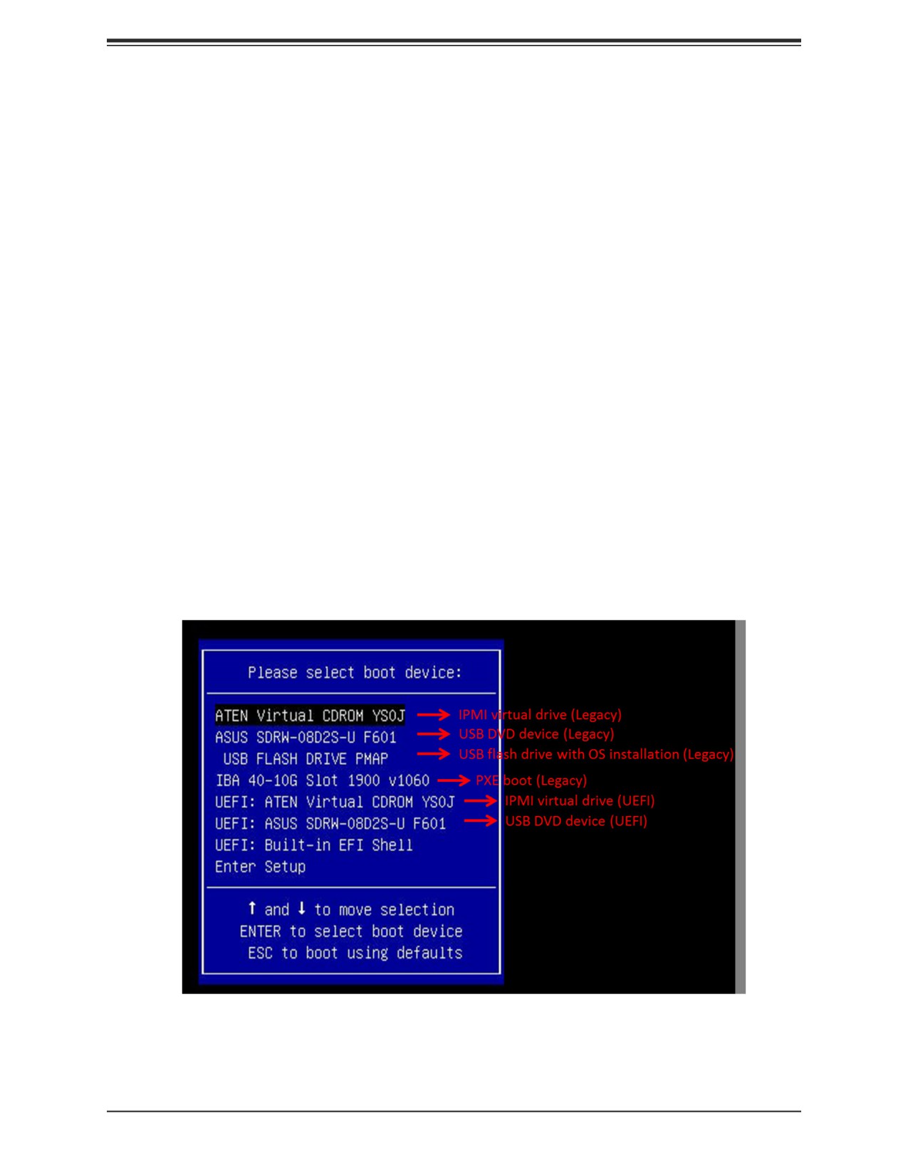
2. Boot from a bootable device with Windows OS installation. You can see a bootable
device list by pressing F11 during the system startup.
Figure 8-1. Select Boot Device
77
Chapter 8: Blade Software
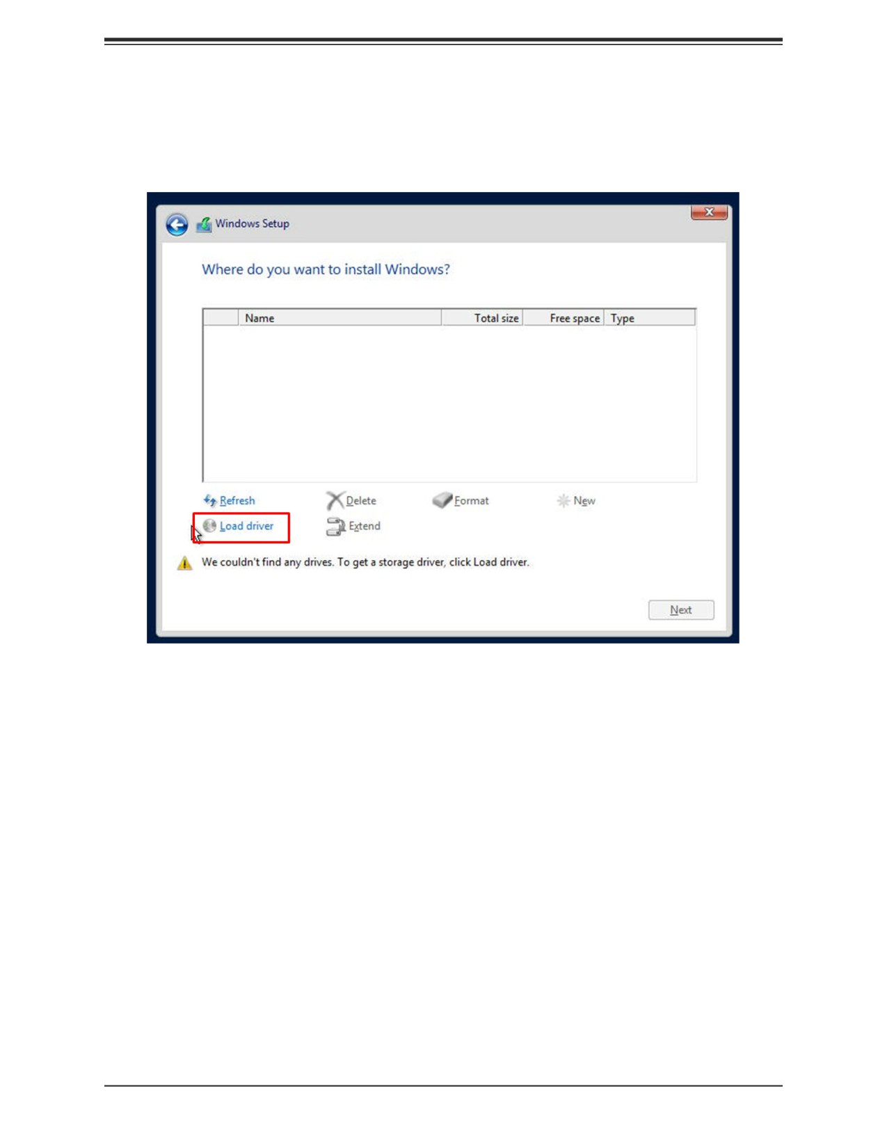
3. During Windows Setup, continue to the dialog where you select the drives on which to
install Windows. If the disk you want to use is not listed, click on “Load driver” link at the
bottom left corner.
Figure 8-2. Load Driver Link
To load the driver, browse the USB flash drive for the proper driver files.
• For RAID, choose the SATA/sSATA RAID driver indicated then choose the storage drive
on which you want to install it.
• For non-RAID, choose the SATA/sSATA AHCI driver indicated then choose the storage
drive on which you want to install it.
4. Once all devices are specified, continue with the installation.
5. After the Windows OS installation has completed, the system will automatically reboot
multiple times.
78
Chapter 8: Blade Software
8.2 Driver Installation
The Supermicro website contains drivers and utilities for your system at https://www.
supermicro.com/wdl/driver. Some of these must be installed, such as the chipset driver.
After accessing the website, go into the CDR_Images (in the parent directory of the above
link) and locate the ISO file for your motherboard. Download this file to to a USB flash drive
or a DVD. (You may also use a utility to extract the ISO file if preferred.)
Another option is to go to the Supermicro website at http://www.supermicro.com/products/.
Find the product page for your motherboard, and "Download the Latest Drivers and Utilities".
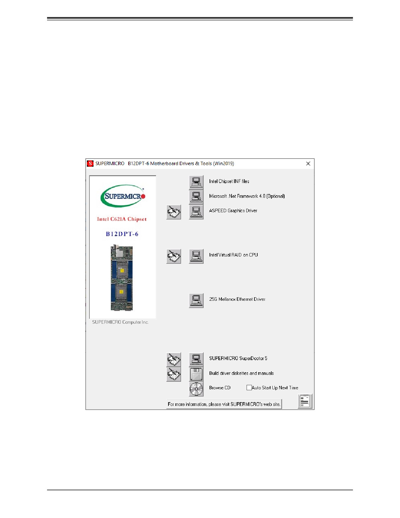
Insert the flash drive or disk and the screenshot shown below should appear.
Figure 8-3. Driver & Tool Installation Screen
Note: Click the icons showing a hand writing on paper to view the readme files for each item.
Click the computer icons to the right of these items to install each item (from top to the bottom)
one at a time. After installing each item, you must reboot the system before moving on to the
next item on the list. The bottom icon with a CD on it allows you to view the entire contents.
79