SuperBlade Server SBS-820H-420P. USER’S MANUAL (Revision 1.0) - page 1
SuperBlade® Server
SBS-820H-420P
USER’S MANUAL
Revision 1.0
The information in this User’s Manual has been carefully reviewed and is believed to be accurate. The vendor assumes
no responsibility for any inaccuracies that may be contained in this document, and makes no commitment to update
or to keep current the information in this manual, or to notify any person or organization of the updates. Please Note:
For the most up-to-date version of this manual, please see our website at www.supermicro.com.
Super Micro Computer, Inc. ("Supermicro") reserves the right to make changes to the product described in this manual
at any time and without notice. This product, including software and documentation, is the property of Supermicro and/
or its licensors, and is supplied only under a license. Any use or reproduction of this product is not allowed, except
as expressly permitted by the terms of said license.
IN NO EVENT WILL Super Micro Computer, Inc. BE LIABLE FOR DIRECT, INDIRECT, SPECIAL, INCIDENTAL,
SPECULATIVE OR CONSEQUENTIAL DAMAGES ARISING FROM THE USE OR INABILITY TO USE THIS PRODUCT
OR DOCUMENTATION, EVEN IF ADVISED OF THE POSSIBILITY OF SUCH DAMAGES. IN PARTICULAR, SUPER
MICRO COMPUTER, INC. SHALL NOT HAVE LIABILITY FOR ANY HARDWARE, SOFTWARE, OR DATA STORED
OR USED WITH THE PRODUCT, INCLUDING THE COSTS OF REPAIRING, REPLACING, INTEGRATING,
INSTALLING OR RECOVERING SUCH HARDWARE, SOFTWARE, OR DATA.
Any disputes arising between manufacturer and customer shall be governed by the laws of Santa Clara County in the
State of California, USA. The State of California, County of Santa Clara shall be the exclusive venue for the resolution
of any such disputes. Supermicro's total liability for all claims will not exceed the price paid for the hardware product.
FCC Statement: This equipment has been tested and found to comply with the limits for a Class A or Class B digital
device pursuant to Part 15 of the FCC Rules. These limits are designed to provide reasonable protection against
harmful interference when the equipment is operated in industrial environment for Class A device or in residential
environment for Class B device. This equipment generates, uses, and can radiate radio frequency energy and, if not
installed and used in accordance with the manufacturer’s instruction manual, may cause harmful interference with
radio communications. Operation of this equipment in a residential area is likely to cause harmful interference, in
which case you will be required to correct the interference at your own expense.
California Best Management Practices Regulations for Perchlorate Materials: This Perchlorate warning applies only
to products containing CR (Manganese Dioxide) Lithium coin cells. “Perchlorate Material-special handling may apply.
See www.dtsc.ca.gov/hazardouswaste/perchlorate”.
WARNING: This product can expose you to chemicals including
lead, known to the State of California to cause cancer and birth
!
defects or other reproductive harm. For more information, go
to www.P65Warnings.ca.gov.
The products sold by Supermicro are not intended for and will not be used in life support systems, medical equipment,
nuclear facilities or systems, aircraft, aircraft devices, aircraft/emergency communication devices or other critical
systems whose failure to perform be reasonably expected to result in significant injury or loss of life or catastrophic
property damage. Accordingly, Supermicro disclaims any and all liability, and should buyer use or sell such products
for use in such ultra-hazardous applications, it does so entirely at its own risk. Furthermore, buyer agrees to fully
indemnify, defend and hold Supermicro harmless for and against any and all claims, demands, actions, litigation, and
proceedings of any kind arising out of or related to such ultra-hazardous use or sale.
Manual Revision 1.0
Release Date: July 12, 2021
mk
Unless you request and receive written permission from Super Micro Computer, Inc., you may not copy any part of this
document. Information in this document is subject to change without notice. Other products and companies referred
to herein are trademarks or registered trademarks of their respective companies or mark holders.
All rights reserved.
Printed in the United States of America
Preface
Preface
About this Manual
This manual is written for professional system integrators and PC technicians. It provides
information for the installation and use of the server. Installation and maintenance should be
performed by experienced technicians only.
Please refer to the SBS-820H-420P system specifications page on our website for updates
Notes
For your system to work properly, please follow the links below to download all necessary
drivers/utilities and the user’s manual for your server.
If you have any questions, please contact our support team at:
support@supermicro.com
This manual may be periodically updated without notice. Please check the Supermicro website
for possible updates to the manual revision level.
Secure Data Deletion
A secure data deletion tool designed to fully erase all data from storage devices can be found
Lot9_Secure_Data_Deletion_Utility/
Warnings
Special attention should be given to the following symbols used in this manual.
Warning! Indicates important information given to prevent equipment/property damage
or personal injury.
Warning! Indicates high voltage may be encountered when performing a procedure.
3
Preface
Contents
Chapter 1 Introduction
1.1 Overview
9
1.2 System Features
10
Front View
10
Drive Carrier Indicators
11
Blade Control Panel
12
Rear View
13
Power Supply Indicator
14
Top View, Blade
15
1.3 Blade Motherboard Layout
16
Quick Reference
17
Motherboard Block Diagram
18
Chapter 2 Server Installation
2.1 Overview
19
2.2 Unpacking the System
19
2.3 Preparing for Setup
19
Choosing a Setup Location
19
Rack Precautions
20
Server Precautions
20
Rack Mounting Considerations
20
Ambient Operating Temperature
20
Airflow
21
Mechanical Loading
21
Circuit Overloading
21
Reliable Ground
21
2.4 Installing the Enclosure
22
Chapter 3 Installation and Setup
3.1 Unpacking the System
24
3.2 Removing Power from the System
24
3.3 Powering Up or Down the Blade
25
Powering Up a Blade Unit
25
Powering Down a Blade Unit
25
4
Preface
3.4
Installing or Removing the Blade Unit
26
Installing a Blade Unit into the Enclosure
26
Removing a Blade Unit from the Enclosure
26
3.5
Removing and Replacing the Blade Cover
27
3.6
Processor and Heatsink Installation
28
The Processor Carrier Assembly
29
The Processor Heatsink Module (PHM)
31
Installing the PHM into the CPU Socket
32
Removing the PHM from the CPU Socket
35
Removing the Processor Carrier Assembly from the PHM
36
Removing the Processor from the Carrier Assembly
37
3.7
Memory
38
Memory Support
38
Memory Population Guidelines
39
Guidelines Regarding Mixing DIMMs
39
DIMM Construction
39
Memory Population Sequence
39
Installing Memory
41
3.8
Motherboard Battery
42
3.9
Storage Drives
43
Installing Drives
43
Hot-Swap for NVMe Drives
46
Checking the Temperature of an NVMe Drive
47
M.2 Storage
47
3.10 Cooling
48
Fans, Enclosure
48
Auxiliary Fans
48
Air Shrouds, Blade
49
Checking the Server Air Flow
50
Overheating
50
3.11Installing Components
51
Chapter 4 Power
4.1 Module Description
52
Power Cord
52
5
Preface
4.2 Installing a Power Supply
53
Removing a Power Supply
54
4.3 Power Supply Failure
54
Redundant Power Supplies
54
4.4 Power Management
55
Backup Battery Power
55
4.5 Power Supply Specifications
56
Chapter 5 Chassis Management Module
5.1
Features
57
Capabilities
58
Module Redundancy
58
Determining Master/Slave Modules Status
58
5.2
Installation
59
5.3
Configuring the CMM
59
Configuring the CMM in Windows OS:
60
5.4
CMM Functions
62
Remote KVM over IP
62
Remote Storage (Virtual Media)
62
Serial Over LAN (SOL)
62
Monitoring Functions
63
Power Consumption Management
63
5.5
USB Ports and Reset Button
63
5.6
Firmware
64
5.7
Web-based Management Utility
64
Supported Browsers
64
Network Connection/Login
64
Address Defaults
65
Home Page
65
Chapter 6 SuperBlade HDR 200G InfiniBand Blade Switch
6.1 Overview
66
Module Managment
66
6.2 Features
67
6.3 Installation
68
6
Preface
6.4 Specifications
69
Hardware Specifications
69
Physical & Environmental Specifications
69
Power Specifications
69
Enclosure Compatibility
69
6.5 Port Mapping
70
6.6 Cabling and Transceiver Compatibility
71
Chapter 7 Motherboard Connections
7.1 Power Connections
72
7.2 Headers and Connectors
72
7.3 Jumpers
74
Explanation of Jumpers
74
7.4 LED Indicators
75
Chapter 8 Blade Software
8.1 Installing the Operating System
76
Linux Installation with Two Storage Drives—Note
76
Microsoft Windows OS Installation
77
8.2 Driver Installation
79
8.3 SuperDoctor® 5
80
8.4 BMC
81
BMC ADMIN User Password
81
Chapter 9 Optional Components
9.1 TPM Security Module
82
9.2 Intel Virtual RAID on CPU (VROC)
83
Requirements and Restrictions
83
Supported SSDs and Operating Sytems
83
Additional Information
84
Hardware Key
84
Configuring NVMe RAID Manually
85
Status Indications
90
Hot Swap Drives
90
Hot-unplug
90
Hot-plug
90
Related Information Links
90
7
Preface
Chapter 10 Troubleshooting and Support
10.1 Information Resources
91
Website
91
Direct Links for the SBS-820H-420P System
91
Direct Links for General Support and Information
91
10.2 BMC Interface
92
10.3
Troubleshooting Procedures
93
No Power
93
No Video
94
System Boot Failure
94
Memory Errors
94
Losing the System Setup Configuration
94
When the System Becomes Unstable
94
10.4
BIOS Error Beep (POST) Codes
96
Additional BIOS POST Codes
96
10.5
Crash Dump Using the BMC Dashboard
97
10.6
UEFI BIOS Recovery
98
Overview
98
Recovering the UEFI BIOS Image
98
Recovering the Main BIOS Block with a USB Device
98
10.7
CMOS Clear
103
10.8
BMC Reset
103
10.9
Where to Get Replacement Components
104
10.10 Reporting an Issue
104
Technical Support Procedures
104
Returning Merchandise for Service
104
Vendor Support Filing System
105
10.11 Feedback
105
10.12 Contacting Supermicro
106
Appendix A Standardized Warning Statements for AC Systems
Appendix B System Specifications
8
Chapter 1: Introduction
Chapter 1
Introduction
1.1 Overview
This chapter provides a brief outline of the functions and features of the SuperBlade server
System SBS-820H-420P.
System Overview
Blades
Twenty SBI-420P-1T3N blade servers
Enclosure
8U SBE-820H-822
Motherboard
(per node) B12DPT-6
(per node) Dual P+ (LGA4189) sockets 3rd Gen Intel Xeon Scalable; TDP up to 220W
Processor
CPU, TDP up to 270W with optional liquid cooling kit
(per node) Sixteen DIMM slots, 3DS ECC DDR4-3200MHz RDIMM/LRDIMM or Intel
Optane PMem 200 Series*
Memory
(up to 4TB for DDR4, or up to 4TB of PMem and 2TB DDR4)
* Note: PMem 200 Series are supported on 3rd gen Intel Xeon Scalable Platinum, Gold
and selected Silver processors.
HDR 200G InfiniBand Switch
Switch Modules
External: 20x 200G HDR IB uplink
Internal: 1x 200G HDR IB to each node downlink
(per node) Two hot-swap 2.5" SATA or NVMe drives, and one hot-swap 2.5" SATA drive
Drive Support
One M.2 SSD; an optional add-on module can provide four additional M.2 SSDs
Two SuperDOM (disk on modules)
Eight heavy duty fans with Optimal Fan Speed Control
System Cooling
Air Shrouds
Optional liquid cooling support
Power
Eight Redundant 2200W Power Supplies, 80Plus Titanium level
Form Factor
8U; (WxHxD) 14" x 17.6" x 32" in. (356 x 447 x 813 mm)
A link to the Quick Reference Guide can be found on the product page of the Supermicro
website.
The following safety models associated with the SBS-820H-420P have been certified as
compliant with UL and CSA; B820-22
9
Chapter 1: Introduction
1.2 System Features
The following views of the system display the main features. Refer to Appendix B for additional
specifications.
Front View
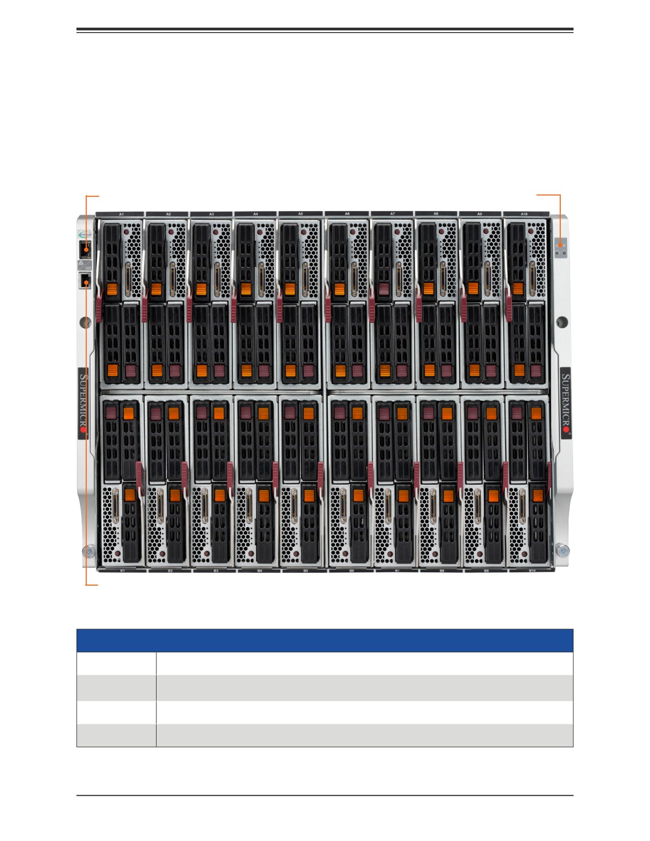
LAN Port
Status
Indicators
Console Port
Figure 1-1. Front View
System Front Features
Feature
Description
Status
Green: All blades, switch modules, CMM, power supplies, and fans are operating normally.
Indicators
Red: Critical warning—some components or modules are not operating normally.
LAN Port
Network port for the blade system
Console Port
Serial console port for the CMM
10
Chapter 1: Introduction
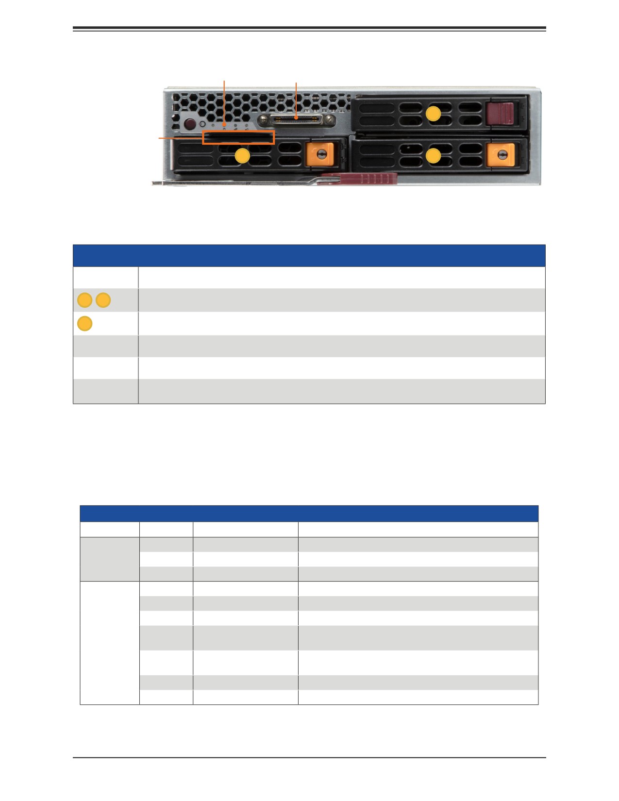
Control Panel
KVM
2
Service/Asset Tab
with BMC Password
0
1
Figure 1-2. Blade Front View
Blade Front View
Item
Description
0
1
Two hot-swap 2.5" SATA or NVMe
2
One hot-swap 2.5" SATA
Control Panel
Power button and status indicators
KVM
Keyboard, video, mouse connector
Service/Asset
Pull-out identifier (with BMC ADMIN default password sticker)
Tag
Drive Carrier Indicators
Each drive carrier has two LED indicators: an activity indicator and a status indicator. For RAID
configurations using a controller, the meaning of the status indicator is described in the table
below. For OS RAID or non-RAID configurations, some LED indications are not supported,
such as hot spare. For VROC configurations, refer to the VROC section in this manual.
Drive Carrier LED Indicators
Color
Blinking Pattern
Behavior for Device
Activity
Blue
Solid On
Idle SAS or NVMe drive installed
LED
Blue
Blinking
I/O activity
Off
Idle SATA or no drive
Status
Red
Solid On
Failure of drive with RSTe support
LED
Red
Blinking at 1 Hz
Rebuild drive with RSTe support
Red
Blinking at 4 Hz
Identify drive with RSTe support
Red
Blinking with two blinks
Hot spare for drive with RSTe support
and one stop at 1 Hz
Red
On for five seconds,
Power on for drive with RSTe support
then off
Amber
Blinking
Safe to remove NVMe drive
Green
Solid on
Ejecting an NVMe drive
11
Chapter 1: Introduction
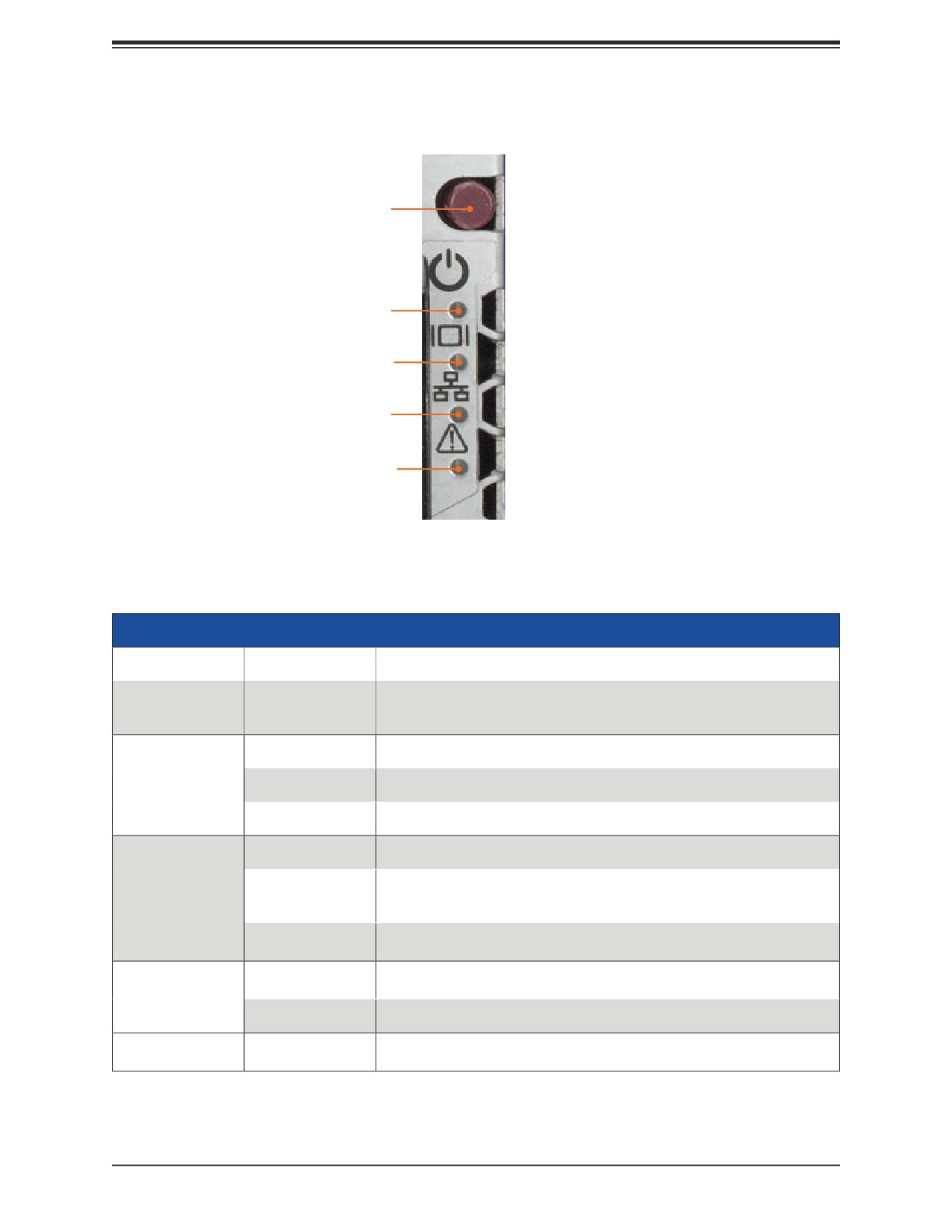
Blade Control Panel
Power Button
Power LED
KVM/UID LED
NIC LED
System Fail LED
Figure 1-3. Control Panel
Control Panel Features
Features
Color/State
Description
Push briefly to apply or remove primary power to the server. Standby
Power Button
power is maintained.
Push and hold to reset the BMC. See "BMC Reset" in Chapter 6.
Green
Power on
Power LED
Amber, flashing
Before the BMC is ready, blinks until every node is ready
Amber, steady
Power off
Blue, steady
Indicates that KVM has been initialized
Unit Identifier indicator (The UID function is activated with a
Blue, flashing
KVM/UID LED
management program.)
slowly
or BMC reboot (see Power Button above)
Blue, flashing
BMC returning to factory settings (see Power Button above)
quickly
Indicates traffic (Tx and RX data) on the LAN connection to this blade
Green, flashing
module
NIC LED
Orange, flashing
Indicates traffic over the network (when present in the system)
Indicates a fatal error. This may be a memory error, a VGA error or any
System Fail LED
Red
other fatal error that prevents the operating system from booting.
12
Chapter 1: Introduction
Rear View
1
1
1
1
3
2
2
2
5
5
4
1
1
1
1
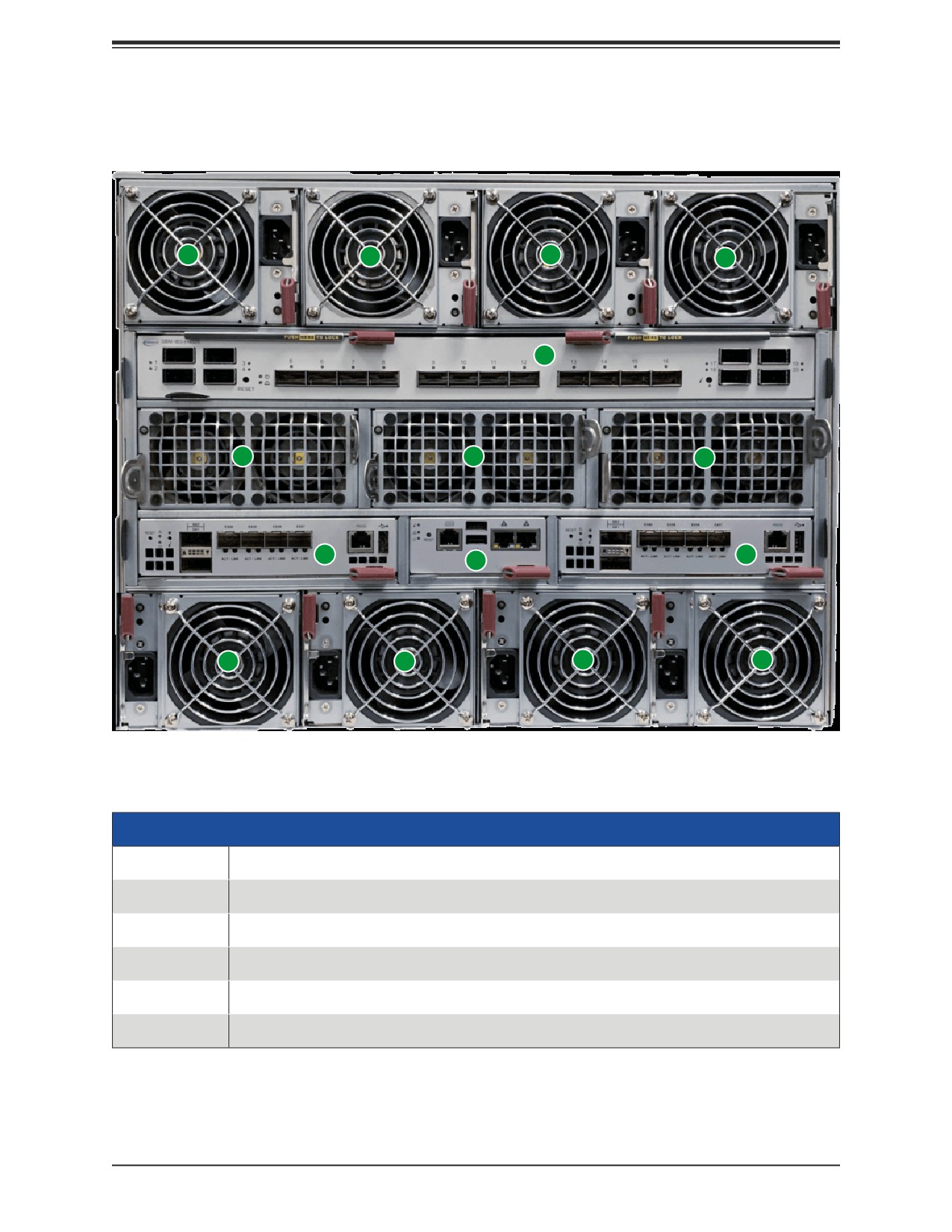
Figure 1-4. SBE-820H-822 Rear View
Rear Features
Feature
Description
1
Eight power supply modules with fans (see Chapter 4)
2
Three pairs of auxiliary fans
3
200Gb InfiniBand switch (see Chapter 6)
4
Chassis Management Module (CMM) (see Chapter 5)
5
Two 25Gb Ethernet switch modules
13
Chapter 1: Introduction
Power Supply Indicator
LEDs on the power supplies indicate the status of the module.
Power Supply Indicator
LED Color and State
Power Supply Condition
Solid Green
Indicates that the power supply is on
Blinking Green
Indicates that the power supply is plugged in and turned off by the system.
Blinking Amber
Indicates that the power supply has a warning condition and continues to operate.
Indicates that the power supply is plugged in, and is in an abnormal state. The
Solid Amber
system might need service. Please contact Supermicro technical support.
Off
No AC power to modules
14
Chapter 1: Introduction
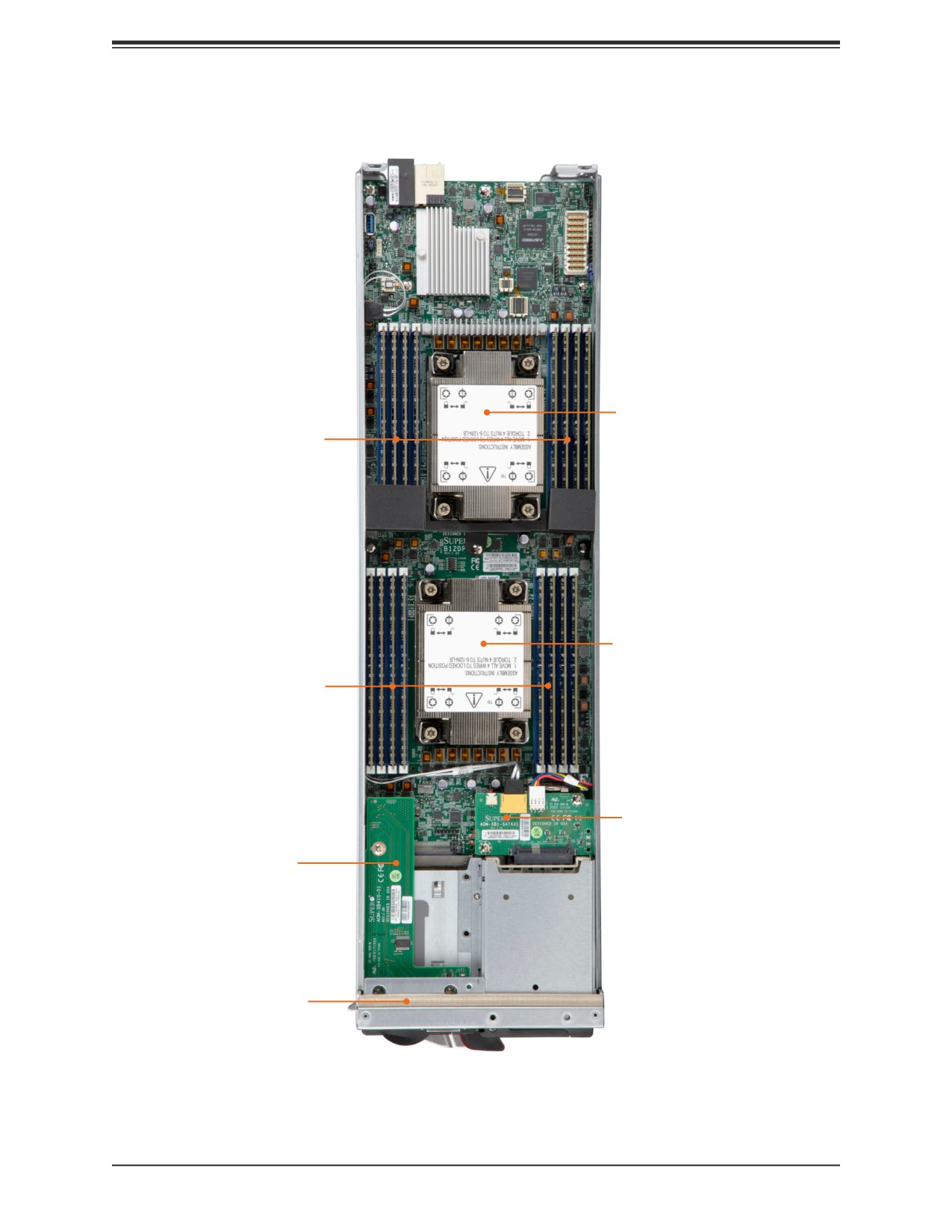
Top View, Blade
CPU under
Heatsink
Memory
under an
Air Shroud
CPU under
Heatsink
Memory
under an
Air Shroud
M.2 Slot
under PCB
Control Board
Asset Tab
Pull-out
Figure 1-5. System: Top View
15
Chapter 1: Introduction
1.3 Blade Motherboard Layout
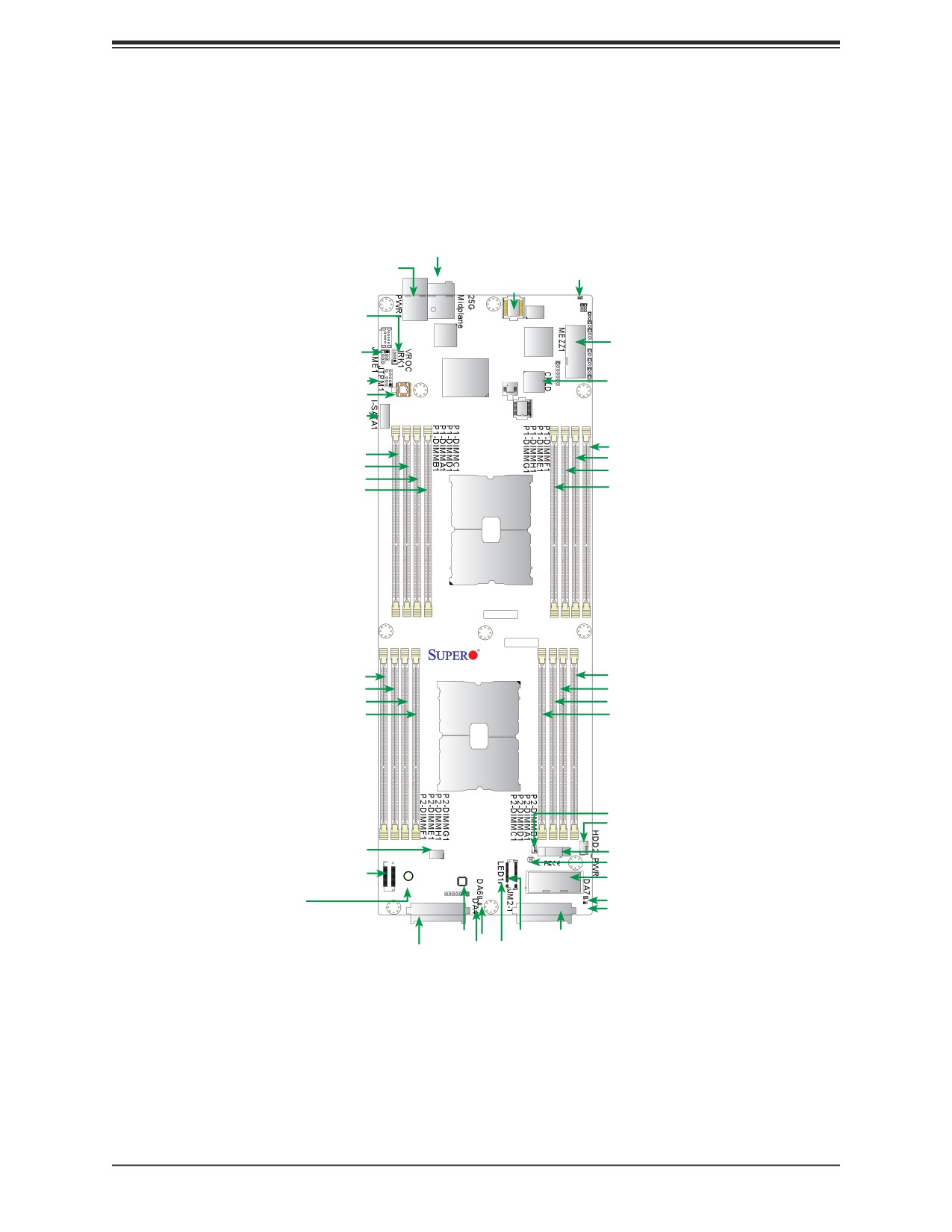
Below is a layout of the B12DPT-6 motherboard with jumper, connector and LED locations
shown. See the table on the following page for descriptions. For detailed descriptions, pinout
information and jumper settings, refer to Chapter 7 or the Motherboard Manual.
25G Midplane
MB PWR
MP1
LEDM1
BMC Flash
LEDM1
BMC
VROC(JRK1)
Memory
MB PWR
BMC Flash
MEZZ1
JPME1
LAN CTRL
BMC
Dual Boot
for CPLD
CPLD
JTPM1
BIOS
BIOS
PCH
CPLD
I-SATA1
Flash
P1-DIMMF1
P1-DIMMB1
P1-DIMME1
P1-DIMMA1
P1-DIMMH1
P1-DIMMD1
P1-DIMMG1
P1-DIMMC1
CPU1
BAR CODE
MAC CODE
B12DPT-6
REV:1.00
P2-DIMMF1
P2-DIMMB1
P2-DIMME1
P2-DIMMA1
P2-DIMMH1
P2-DIMMD1
P2-DIMMG1
P2-DIMMC1
CPU2
JLED
HDD2 PWR
FAN1
BT1
FAN1
JLED
BT1
JFP1
JBT1
JBT1
JFP1
CPLD0
MEZZ2
M.2
MH
MEZZ2
M.2 MH
D7
DA5
D5
(Mounting Hole)
HDD0
HDD1
CPLD0
D6
JM2-1 HDD1
HDD0
D4
LED1
Figure 1-7. Motherboard Layout
16

Chapter 1: Introduction
Quick Reference
Jumper
Description
Default Setting
JBT1
CMOS Clear
Open (Normal)
JPME1
ME Manufacturing Recovery
Pins 1-2 (Normal)
Connector
Description
BT1
Onboard CMOS battery
CPLD0
Complex Programmable Logic Device (CPLD) chip
FAN1
Cooling fan header reserved for liquid cooling
HDD0/HDD1
Front accessible Hard Driver Connector #0/Hard Driver Connector #1
HDD2_PWR
Power connector for HDD 2
JBT1
Contacts for CMOS Clear
JFP1
Front Panel Control board with KVM & USB 2.0 support (via Cable CBL-0218L)
JLED
HDD2 SATA Activity LED
JM2-1 & M.2 MH
M.2 slot (PCIe 4.0 x4) and M.2 Mounting Hole (M.2 MH)
JTPM1
Trusted Platform Module/Port 80 connector
MEZZ1/MEZZ2
PCI Mezzanine Card Connector 1/Mezzanine Card Connector 2
MP1
Onboard 25G midplane
PWR1
Motherboard Power connector
I-SATA 1
Intel PCH SATA 3.0 port (with RAID 0, 1, 5, 10)
VROC (JRK1)
Intel VROC key header for NVMe RAID support
LED
Description
State: Status
DA4
HDD0 Heartbeat LED
Green: HDD0 Normal; Red: HDD0 Failure
DA5
HDD1 Heartbeat LED
Green: HDD1 Normal; Red: HDD1 Failure
DA6
HDD0 Activity LED
Blue: HDD0 Active
DA7
HDD1 Activity LED
Blue: HDD0 Active
LED1
M.2 Activity LED
Green: M.2 Normal
LEDM1
BMC Activity LED
Green: BMC Normal
17
Chapter 1: Introduction
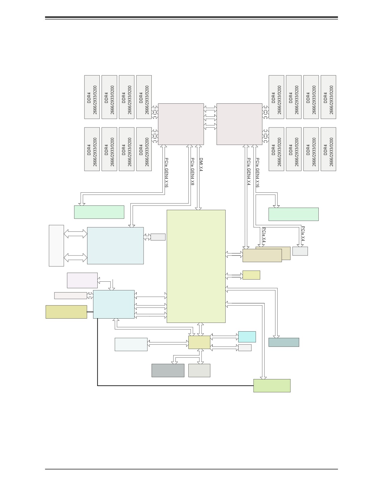
Motherboard Block Diagram
CPU1-B1 CPU1-A1CPU1-D1 CPU1-C1
CPU2-C1 CPU2-D1CPU2-A1CPU2-B1
UPI
10.4/11.2G
C
PU1
C
PU2
P0
P2
UPI
D
DR4
P1
P1
D
D
R
4
UPI
CPU1-F1
CPU1-E1CPU1-H1CPU1-G1
P2
P0
CPU2-G1CPU2-H1CPU2-E1
CPU2-F1
UPI
PEIC:30
PEIC:31
Socket ID: 0
Socket ID: 1
#3
#2
#1
#0
DMI3
DMI3
#0 #1
#2
#3
PCIe X8
MEZZ1
MEZZ2
Mezzanine Connector
(For NIC AOC)
DMI3
Mezzanine Connector
(For SAS AOC)
MP1
U36
10/25G
PCIe GEN3 X8
U46
PORT1
PORT2
SPI
FLASH
Mellanox
T27712A0
6.0 Gb/S
#1
ConnectX-4 Lx En
#0
M.2
10/25G
PCH
SATA/NVMe
PORT0
SAS (Optional)
PORT0
SATA0-1
SSATA0
6.0 Gb/S
#2
LAN3 (To CMM)
SATA
RGRMII
RTL8211FS
SATA2
-VS-CG
USB 3.0
BMC
PCIe GEN2 X1
USB3_4
DDR4
#5
USB2_8
USB 2.0
AST2600
USB2_5
USB 2.0
#12 USB2.0
Temperature Sensor
USB2_7
USB2_1
ESPI
USB2_2
TMP432 RT1/RT2/RT8
SPI
SPI
CPLD
JUSB0
CPLD
FLASH
SPI
USB3.0 Type A
BMC Boot Flash
(PFR)
SPI
DUAL
BOOT
SPI
TPM HEADER
BIOS
Debug Card
JFP1
VGA/COM1/Temperature Sensor
VGA/ USBx2/ COM1
To KVM connector
Figure 1-8. Motherboard Block Diagram
18
Chapter 2: Server Installation
Chapter 2
Server Installation
2.1 Overview
This chapter provides advice and instructions for mounting your system in a server rack.
If your system is not already fully integrated with processors, system memory etc., refer to
Chapter 3 for details on installing those specific components.
Caution: Electrostatic Discharge (ESD) can damage electronic components. To prevent such
damage to PCBs (printed circuit boards), it is important to use a grounded wrist strap, handle
all PCBs by their edges and keep them in anti-static bags when not in use.
2.2 Unpacking the System
Inspect the box in which the system was shipped, and note if it was damaged. If any equipment
appears damaged, file a claim with the carrier.
Decide on a suitable location for the rack unit that will hold the server. It should be situated
in a clean, dust-free area that is well ventilated. Avoid areas where heat, electrical noise and
electromagnetic fields are generated. It will also require a grounded AC power outlet nearby.
Be sure to read the precautions and considerations noted in Appendix A.
2.3 Preparing for Setup
The box in which the system was shipped should include the rackmount hardware needed to
install it into the rack. Please read this section in its entirety before you begin the installation.
Choosing a Setup Location
• The system should be situated in a clean, dust-free area that is well ventilated. Avoid areas
where heat, electrical noise and electromagnetic fields are generated.
• Leave enough clearance in front of the rack so that you can open the front door completely
(~25 inches) and approximately 30 inches of clearance in the back of the rack to allow
sufficient space for airflow and access when servicing.
• This product should be installed only in a Restricted Access Location (dedicated equipment
rooms, service closets, etc.).
19
Chapter 2: Server Installation
• This product is not suitable for use with visual display workplace devices according to §2
of the German Ordinance for Work with Visual Display Units.
Rack Precautions
• Ensure that the leveling jacks on the bottom of the rack are extended to the floor so that
the full weight of the rack rests on them.
• In single rack installations, stabilizers should be attached to the rack. In multiple rack in-
stallations, the racks should be coupled together.
• Always make sure the rack is stable before extending a server or other component from
the rack.
• You should extend only one server or component at a time - extending two or more simul-
taneously may cause the rack to become unstable.
Server Precautions
• Review the electrical and general safety precautions in Appendix A.
• Determine the placement of each component in the rack before you install the rails.
• Install the heaviest server components at the bottom of the rack first and then work your
way up.
• Use a regulating uninterruptible power supply (UPS) to protect the server from power
surges and voltage spikes and to keep your system operating in case of a power failure.
• Allow any drives and power supply modules to cool before touching them.
• When not servicing, always keep the front door of the rack and all covers/panels on the
servers closed to maintain proper cooling.
Rack Mounting Considerations
Ambient Operating Temperature
If installed in a closed or multi-unit rack assembly, the ambient operating temperature of
the rack environment may be greater than the room's ambient temperature. Therefore,
consideration should be given to installing the equipment in an environment compatible with
the manufacturer’s maximum rated ambient temperature (TMRA).
20
Chapter 2: Server Installation
Airflow
Equipment should be mounted into a rack so that the amount of airflow required for safe
operation is not compromised.
Mechanical Loading
Equipment should be mounted into a rack so that a hazardous condition does not arise due
to uneven mechanical loading.
Circuit Overloading
Consideration should be given to the connection of the equipment to the power supply circuitry
and the effect that any possible overloading of circuits might have on overcurrent protection
and power supply wiring. Appropriate consideration of equipment nameplate ratings should
be used when addressing this concern.
Reliable Ground
A reliable ground must be maintained at all times. To ensure this, the rack itself should be
grounded. Particular attention should be given to power supply connections other than the
direct connections to the branch circuit (i.e. the use of power strips, etc.).
To prevent bodily injury when mounting or servicing this unit in a rack, you must take
special precautions to ensure that the system remains stable. The following guidelines
are provided to ensure your safety:
• This unit should be mounted at the bottom of the rack if it is the only unit in the rack.
• When mounting this unit in a partially filled rack, load the rack from the bottom to the top
with the heaviest component at the bottom of the rack.
• If the rack is provided with stabilizing devices, install the stabilizers before mounting or
servicing the unit in the rack.
• Slide rail mounted equipment is not to be used as a shelf or a work space.
• Stability hazard. The rack stabilizing mechanism must be in place, or the rack must be
bolted to the floor before you slide the unit out for servicing. Failure to stabilize the rack
can cause the rack to tip over.
• Do not pick up the server with the front handles. They are designed to pull the system
from a rack only.
21
Chapter 2: Server Installation
2.4 Installing the Enclosure
There are a variety of rack units on the market, which may require a slightly different assembly
procedure. Also see the instructions that came with the rails. This rail set fits a rack between
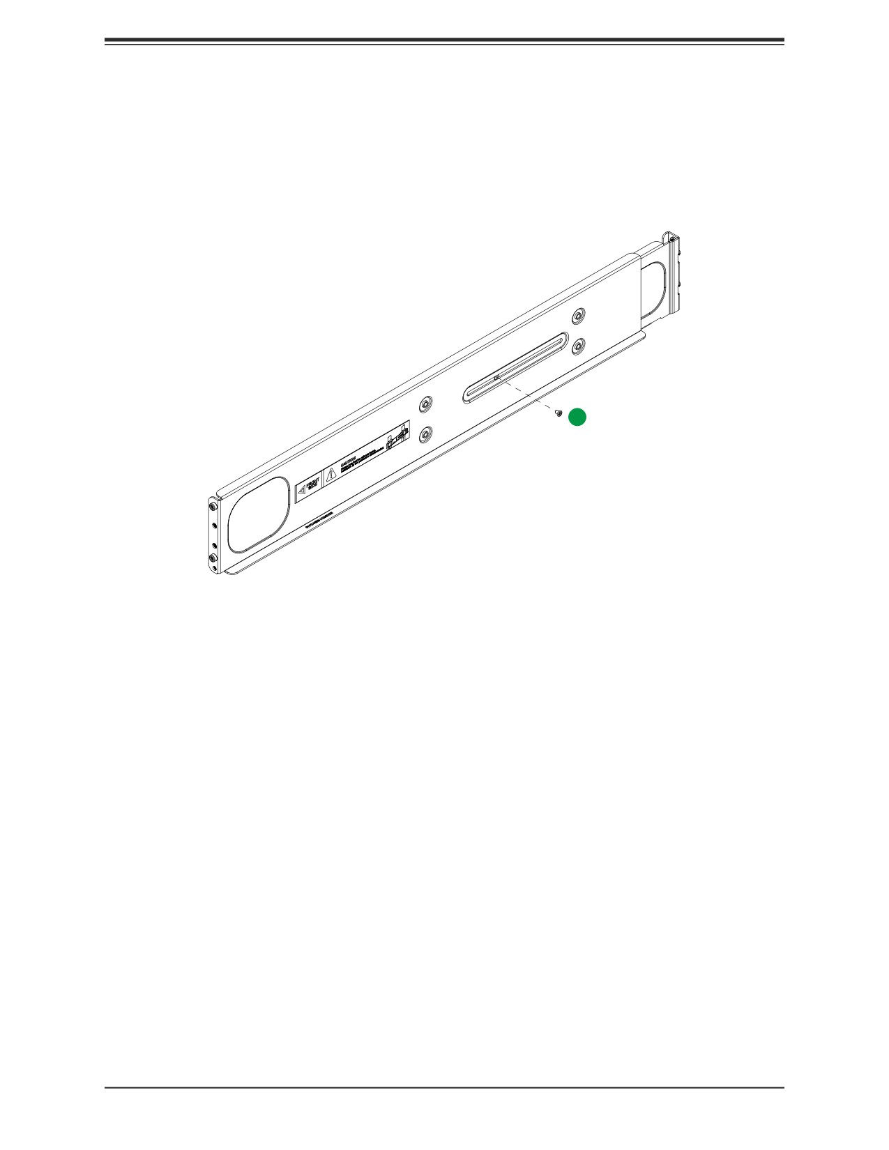
26.8" and 36.4" deep.
1
Figure 2-1. Rack Rails
(Left Rail Assembly Shown)
When installing the enclosure, remove all blades, power supplies, switches and management
modules. Install these modules after the enclosure is mounted.
If desired, use the template to mark the position that the enclosure will occupy on the rack.
The chassis comes with two sets of rack rails, one set for the right side of the chassis and
one for the left.
1. For each rail, sections are screwed together to keep them immobile during shipping.
Release these screws just enough to allow the rails to slide apart.
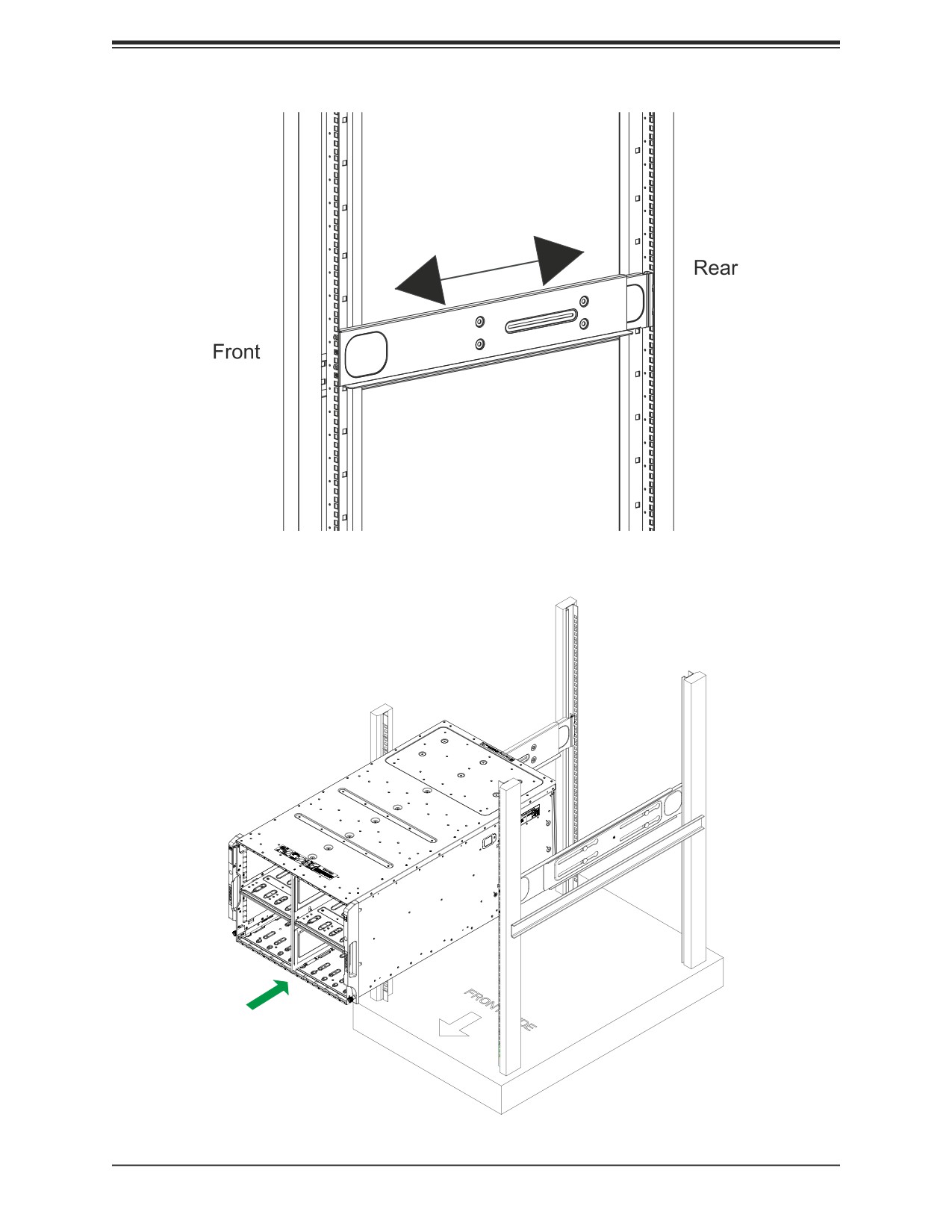
2. Slide the rails apart far enough to match the depth of the rack. Note the arrow on the
rail, which indicates the end that attaches to the front of the rack. Position each rail and
secure the front to the front post of the rack with two flathead screws. Then secure the
back of each rail to the rear of the rack with two flathead screws .
3. Lift the enclosure and slide it into the rack. Use two roundhead screws on each side of
the server to lock it into place.
22
Chapter 2: Server Installation
Figure 2-2. Securing the Left Rail to the Rack
Note: The figure is for illustrative
purposes only. Always install enclosures
at the bottom of the rack first.
Figure 2-3. Installing the Server into the Rack
23
Chapter 3: Installation and Setup
Chapter 3
Installation and Setup
This chapter provides instructions on installing and replacing main system components.
To prevent compatibility issues, only use components that match the specifications or part
numbers.
3.1 Unpacking the System
Inspect the box the system was shipped in and note if it was damaged in any way. If any
equipment appears damaged, please file a damage claim with the carrier who delivered it.
The enclosure should be situated in a clean, dust-free area that is well ventilated. Avoid areas
where heat, electrical noise and electromagnetic fields are generated. It will also require a
grounded AC power outlet nearby. Be sure to read the precautions and considerations noted
in Appendix B.
3.2 Removing Power from the System
Use the following procedure to ensure that power has been removed from the system. This
step is necessary when removing or installing non-hot-swap components, such as the only
CMM in an enclosure.
1. Use the operating systems to power down all blades.
2. Disconnect all the power cords from the power strip or outlet.
3. Disconnect all power cords from the power supply modules.
24
Chapter 3: Installation and Setup
3.3 Powering Up or Down the Blade
Each blade unit may be powered on and off independently from the rest of the blades in the
enclosure.
Powering Up a Blade Unit
A blade unit may be powered up in two ways:
• Press the power button on the blade unit.
• Use IPMIView or the browser based management utility to apply power using either a CMM
module, or by the use of the onboard BMC chip in the blade module.
Powering Down a Blade Unit
A blade unit may be powered down in any of the following ways:
• Press the power button on the blade unit.
• Use IPMIView or the browser based management utility to power down; requires Operator
or Admin privileges on the CMM.
• Use SMCIPMItool when connected to the CMM to power down; requires Operator or Admin
privileges on the CMM.
• Use IPMIview or a browser connected to the onboard BMC chip to power down.
• Use SMCIPMItool to use a Command Line Interface to the onboard BMC chip; requires
Operator or Admin privileges.
25
Chapter 3: Installation and Setup
3.4 Installing or Removing the Blade Unit
Installing a Blade Unit into the Enclosure
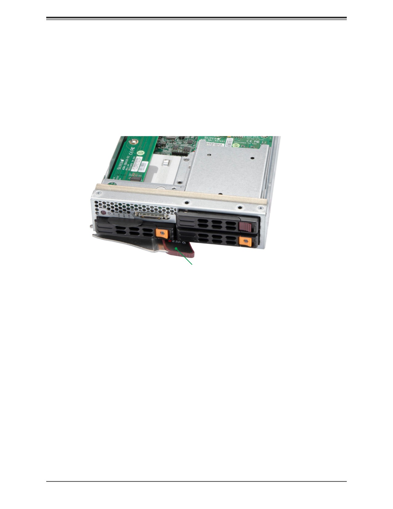
1. Pull the latch lever out, and push the blade into its bay. Caution: Insert the blade
carefully so the rear connectors are not damaged.
2. As the blade is seated in the enclosure, push the lever into its locked position.
Latch Lever
Figure 3-1. Blade Latch Lever
Removing a Blade Unit from the Enclosure
A blade can be removed from the enclosure while other blades continue to operate.
Note: When a blade is removed for a length of time, cover the slot with a dummy to ensure
proper airflow in the enclosure.
Removing a Blade Unit from the Enclosure
1. Power down the blade unit.
2. Pull open the latch lever and use it to pull the blade from the enclosure.
26
Chapter 3: Installation and Setup
3.5 Removing and Replacing the Blade Cover
The blade cover can be removed to access the mainboard and install processors, memory
modules, the onboard battery, etc.
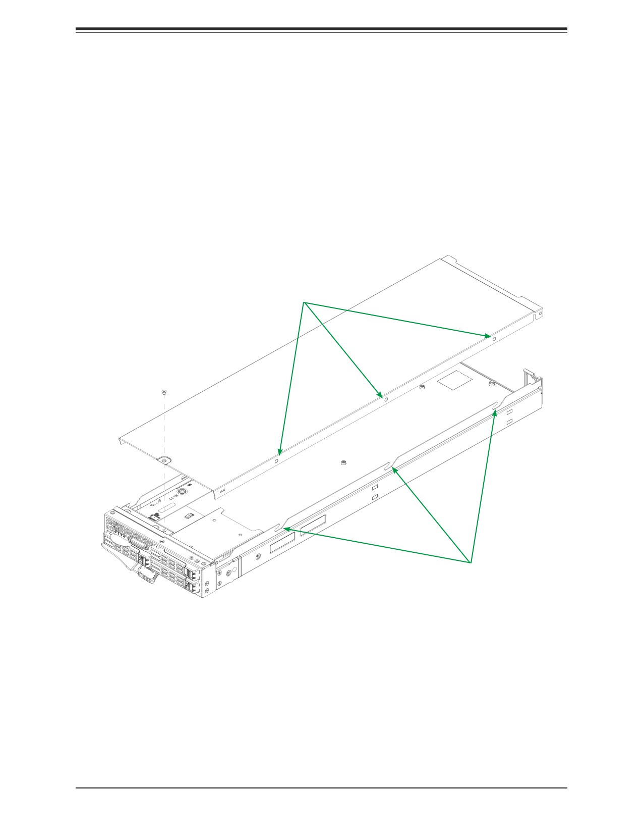
• To remove the cover, remove the screw as illustrated below. Slide the cover toward the
rear and lift it off.
• To replace the cover, fit the six studs on the inside of the cover into the slots of the chas-
sis, then slide the cover toward the front of the blade to lock it into place. Replace the
locking screw.
Studs
Screw
Slots
Figure 3-2. Removing the Cover
27
Chapter 3: Installation and Setup
3.6 Processor and Heatsink Installation
The processor (CPU) and processor carrier should be assembled together first to form
the processor carrier assembly. This will be attached to the heatsink to form the processor
heatsink module (PHM) before being installed onto the CPU socket.
Notes:
• Use ESD protection.
• Remove the blade from the enclosure and the blade chassis cover to expose the moth-
erboard.
• Check that the plastic protective cover is on the blade CPU socket and that none of the
socket pins are bent. If they are, contact your retailer.
• When handling the processor, avoid touching or placing direct pressure on the land grid
array (gold contacts).
• Improper installation or socket misalignment can cause serious damage to the processor
or the socket and may require manufacturer repairs.
• Thermal grease is pre-applied on new heatsinks. No additional thermal grease is needed.
• Refer to the Supermicro website for updates on processor support.
• Graphics in this manual are for illustration only. Your components may look different.
28
Chapter 3: Installation and Setup
The Processor Carrier Assembly
The processor carrier assembly is comprised of the processor and the processor carrier.
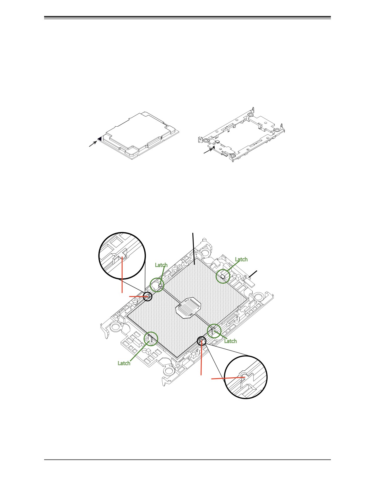
1. Hold the processor with the land grid array (LGA, gold contacts) facing down. Locate the
gold triangle at the corner of the processor and the corresponding hollowed triangle on
the processor carrier as shown below. These triangles indicate the location of pin 1.
Pin 1
Pin 1
Processor
Carrier
2. Turn the processor over (with the gold LGA up). Locate the CPU keys on the processor
and the four latches on the carrier as shown below.
Processor (Reverse Side Up)
Latch
Latch
Carrier (Top Side Up)
CPU Key
Latch
Latch
CPU Key
29
Chapter 3: Installation and Setup
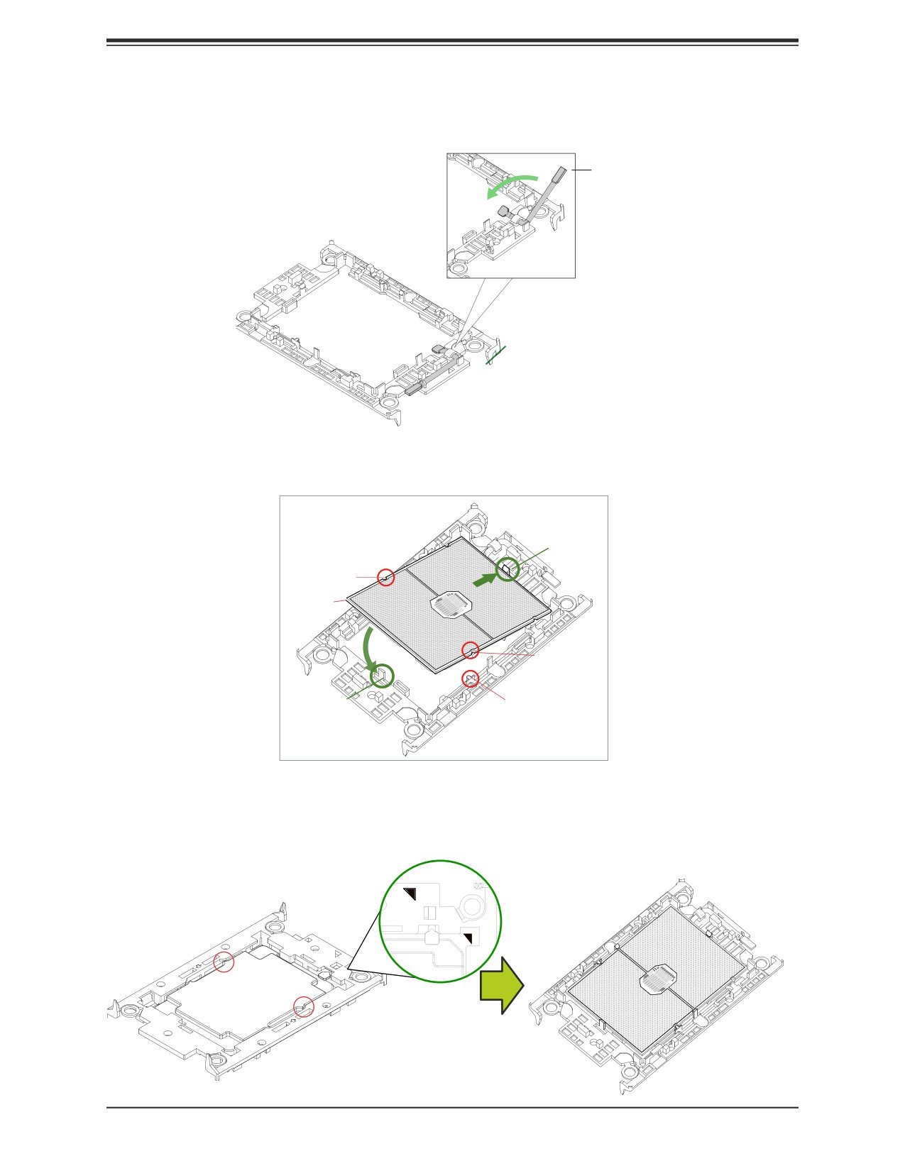
3. Locate the lever on the carrier and, if
necessary, press it down as shown below.
Lever
4. Align the CPU keys on the processor (A & B) with those on the carrier (a & b) as shown
below.
Latch
B
CPU Key (on the
processor)
CPU Key (on
1
the carrier)
b
A
2
CPU Key (on the
processor)
a
CPU Key (on the
Latch
carrier)
5. Carefully place one end of the processor under latch 1 on the carrier, and then press the
other end down until it snaps into latch 2 and is properly seated on the carrier.
Processor Carrier Assembly
Processor Carrier Assembly
(Underside view)
(Top View)
30
Chapter 3: Installation and Setup
The Processor Heatsink Module (PHM)
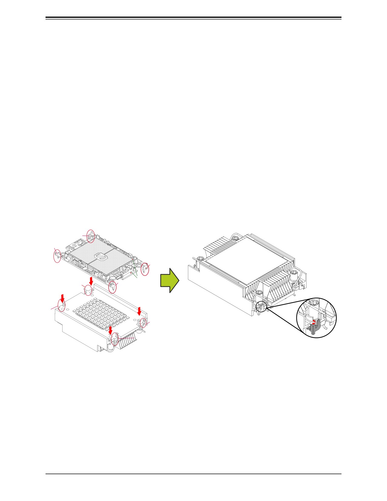
After creating the processor carrier assembly, mount the heatsink onto the carrier assembly
to form the processor heatsink module (PHM).
Note: If this is a new heatsink, the thermal grease has been pre-applied. Otherwise, apply
the proper amount of thermal grease to the underside of the heatsink.
1. Turn the heatsink over with the thermal grease facing up. Note the two triangle cutouts
(A, B) located at the diagonal corners of the heatsink as shown in the drawing below.
2. On the processor carrier assembly, find pin 1, as noted by the triangles. Hold the
processor carrier assembly over so that the gold LGA is facing up.
3. Align clip "a" (pin 1) on the carrier assembly with the triangular cutout A on the heatsink
and b, c, d on the carrier assembly with B, C, D on the heatsink.
4. Push the carrier assembly onto the heatsink, making sure that all four clips on each
corner are properly secured.
Processor Carrier Assembly
d
Heatsink
b
a
Pin1
c
D
B
A
C
Note: These diagrams show an air cooled heatsink.
31
Chapter 3: Installation and Setup
Installing the PHM into the CPU Socket
1. Remove the plastic protective cover from the CPU socket. Gently squeeze the grip tabs
then pull the cover off.
CPU Socket with Plastic Protective Cover
Grip Tabs
32
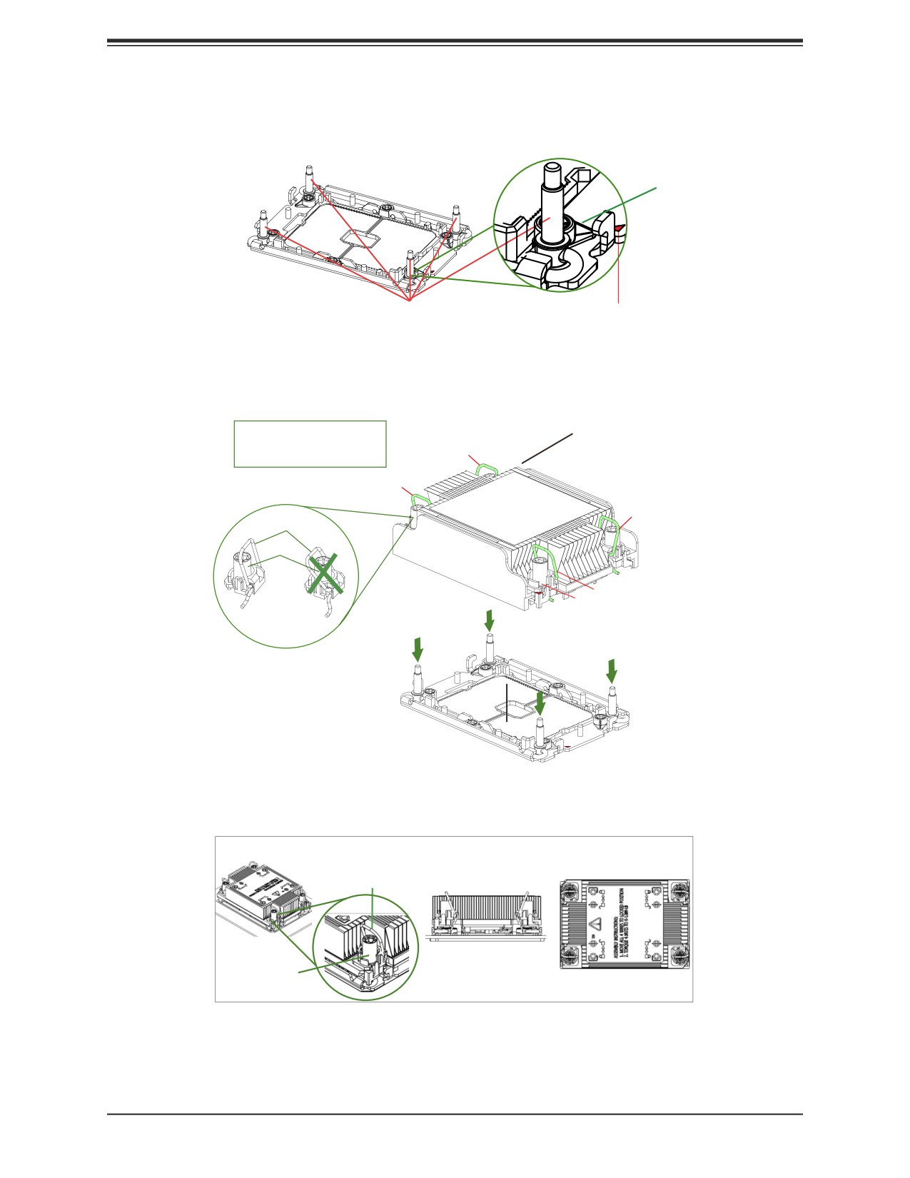
Chapter 3: Installation and Setup
2. Locate four threaded fasteners (a, b, c, d) on the CPU socket.
b
CPU Socket
Threaded Fastener
c
d
a
(a, b, c, d: Threaded Fasteners)
CPU Socket Pin1
3. Locate four PEEK nuts (A, B, C, D) and four rotating wires (1, 2, 3, 4) on the heatsink
as shown below.
Heatsink
A, B, C, D: Peek Nut
1, 2, 3, 4: Rotating Wire
Rotating Wire2
a, b, c, d: Threaded Fastener
B
Rotating Wire 4
D
Rotating Wire 3
Rotating Wire
Peek Nut
C
Rotating Wire 1
Peek Nut
(Unlatched)
A
(latched)
CPU Socket
4. Check that the rotating wires (1, 2, 3, 4) are in the unlatched position as shown.
Unlatched State
Top View
Rotating Wire
Side View
Peek Nut
33
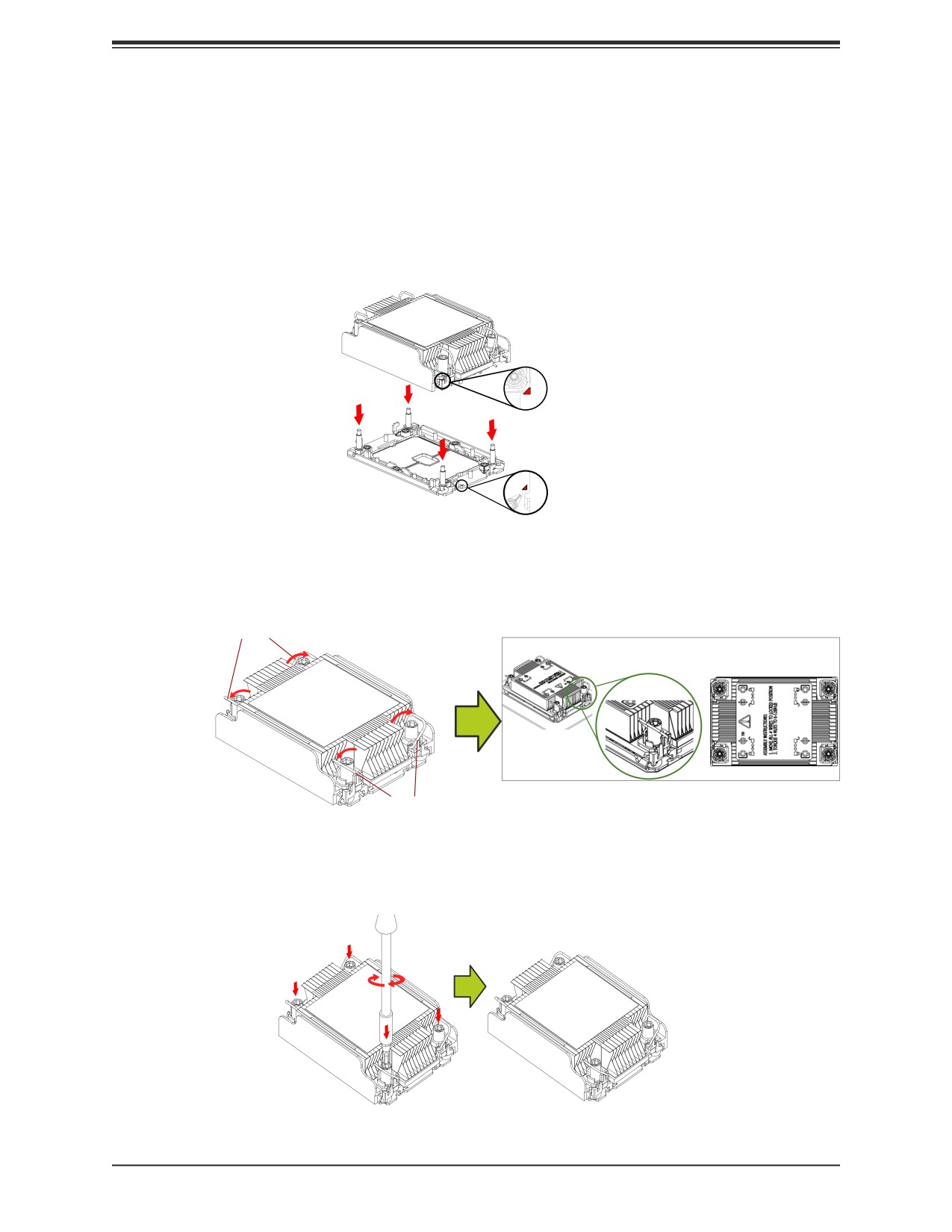
Chapter 3: Installation and Setup
5. Align nut A (next to the triangles and pin 1) on the heatsink with threaded fastener "a"
on the CPU socket. Also align nuts B, C, D on the heatsink with threaded fasteners b, c,
d on the CPU socket.
6. Gently place the heatsink on the CPU socket, making sure that each nut is properly
aligned with its corresponding threaded fastener.
A, B, C, D: Peek Nut on the Heatsink
B
D
C
A
b
d
c
a
a, b, c, d:
Threaded Fastener on the CPU socket
7. Press all four rotating wires outward to latch the PHM onto the CPU socket.
Rotating Wire
Latched State
Top View
Rotating Wire
8. With a t30-bit screwdriver, tighten all PEEK nuts in the sequence of A, B, C, and D with
even pressure not greater than 12 lbf-in.
B
D
C
A
34
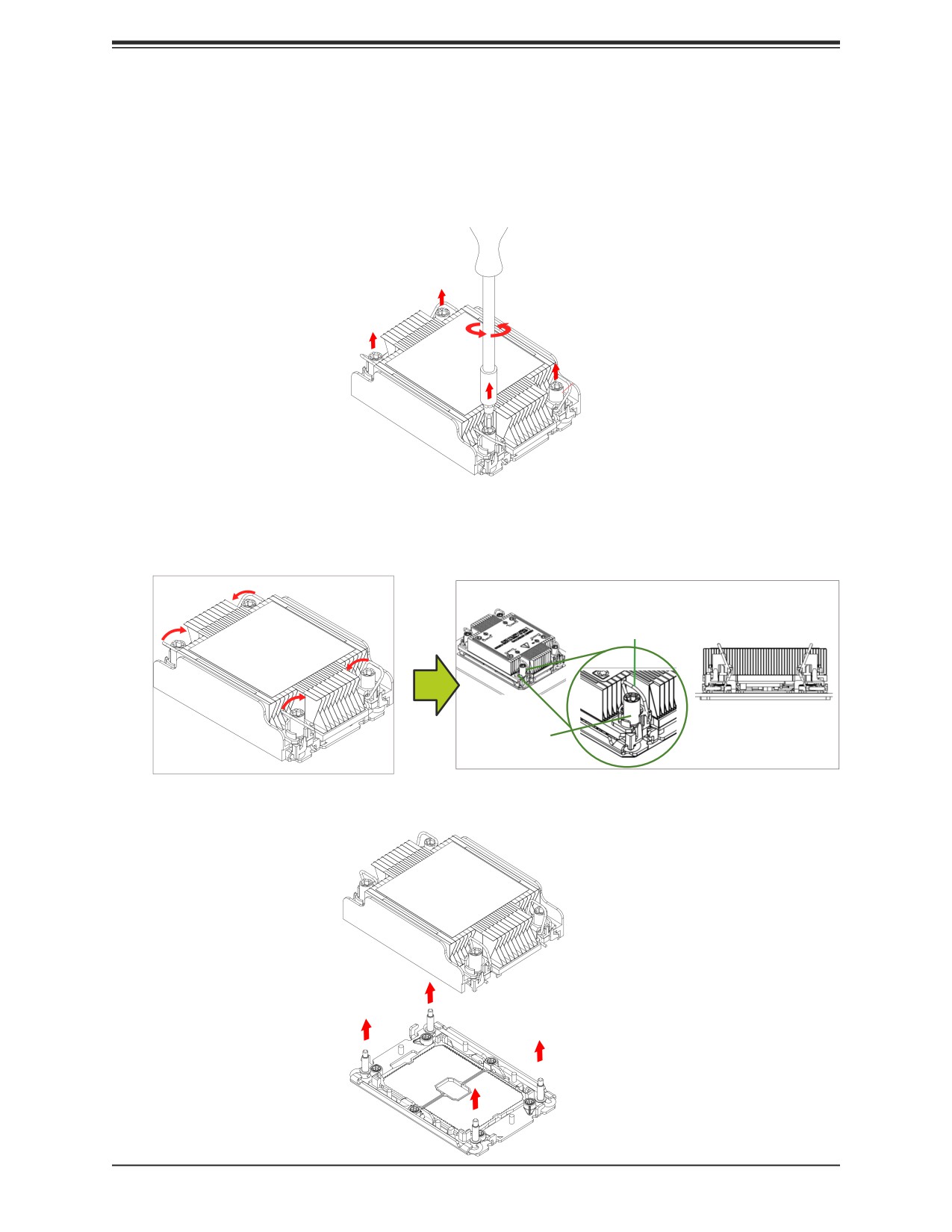
Chapter 3: Installation and Setup
Removing the PHM from the CPU Socket
Be sure the system is shut down and all AC power cords are unplugged.
1. Use a t30-bit screwdriver to loosen the four PEEK nuts on the heatsink in the sequence
of A, B, C, and D.
B
D
Peek Nut
C
A
2. Press the four rotating wires inward to unlatch the PHM as shown below.
Unlatched State
Rotating Wire
Side View
Peek Nut
3. Gently lift the PHM upward to remove it from the CPU socket.
35
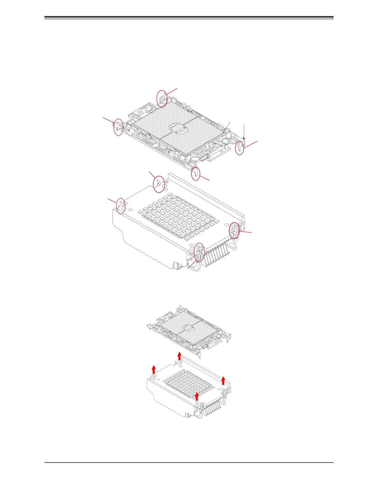
Chapter 3: Installation and Setup
Removing the Processor Carrier Assembly from the PHM
Detach the four plastic clips (a, b, c, d) on the processor carrier assembly from the four corners
of the heatsink (A, B, C, D) as shown below, and lift off the processor carrier assembly.
d
Processor Carrier Assembly
b
Pin 1
Pin 1
a
D
c
B
Heatsink
A
C
36
Chapter 3: Installation and Setup
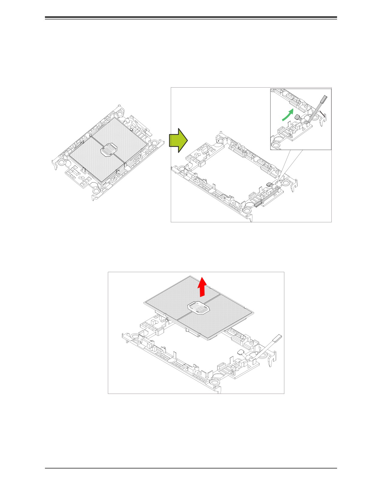
Removing the Processor from the Carrier Assembly
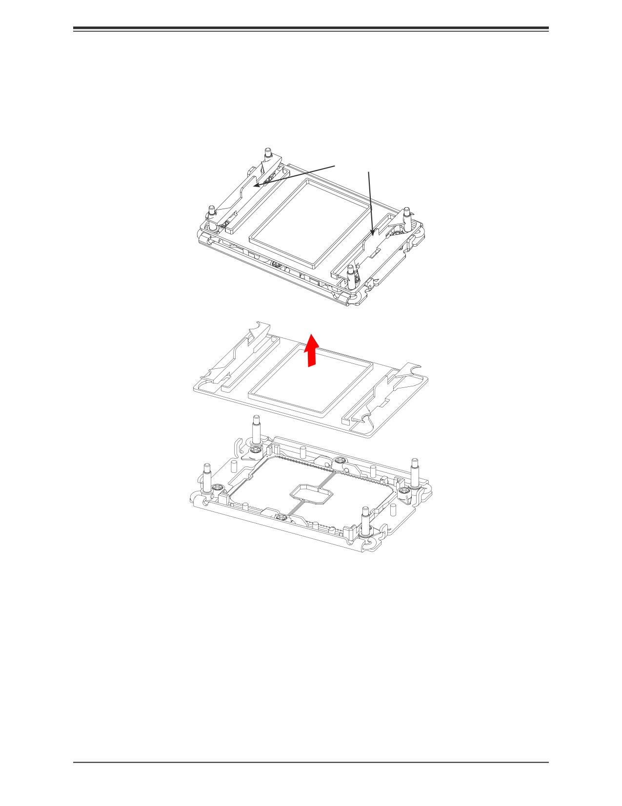
Unlock the lever from its locked position and push it upwards to disengage the processor from
the carrier as shown below right. Carefully remove the processor from the carrier.
Processor Carrier Assembly
Lever
Note: Handle the processor with care to avoid damage.
37
Chapter 3: Installation and Setup
3.7 Memory
Memory Support
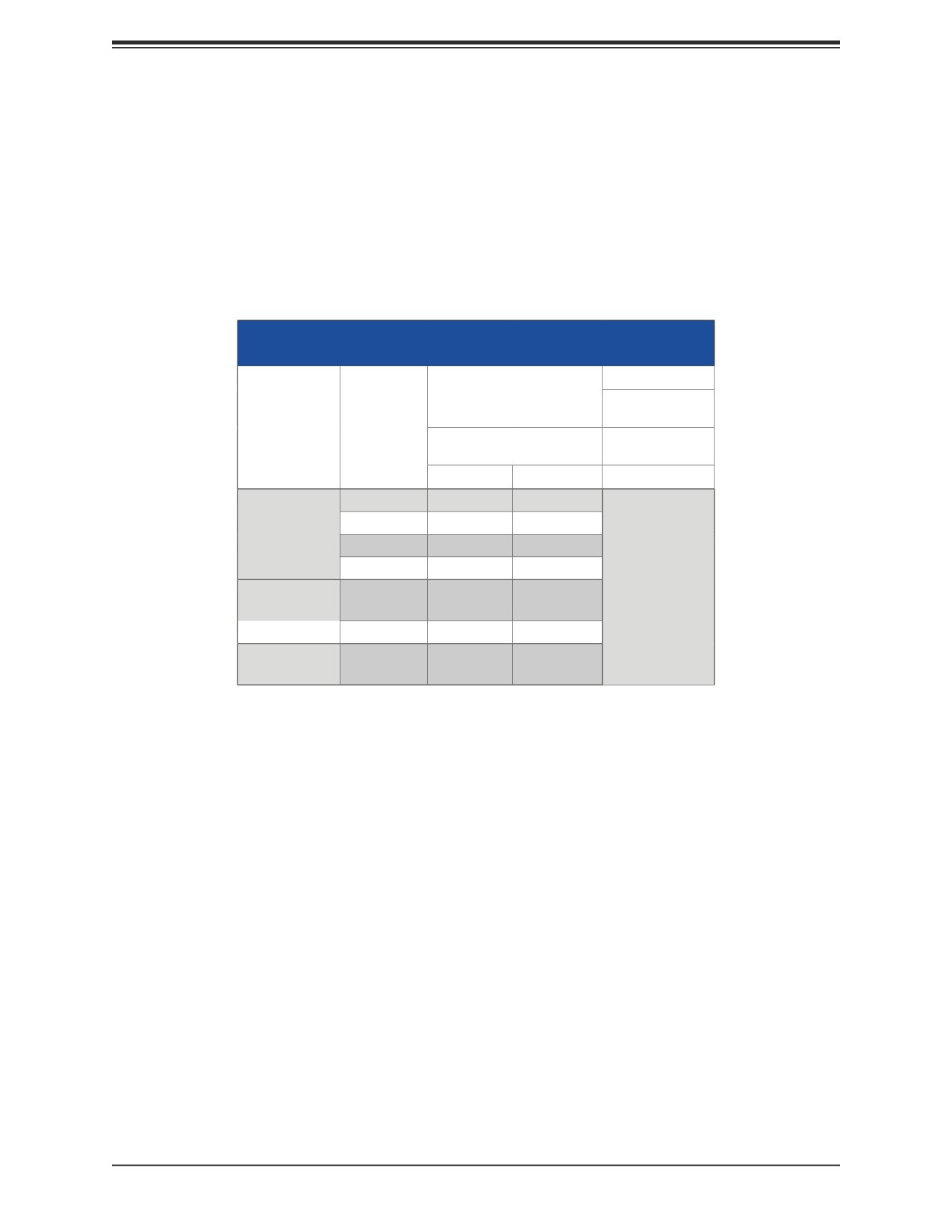
The B12DPT-6 has 16 DIMM slots for up to 4TB of 3DS LRDIMM/LRDIMM/3DS RDIMM/
RDIMM DDR4 (288-pin) ECC memory with speeds of 3200/2933/2666MT/s. For validated
memory, use our Product Resources page.
DDR4 Memory Support for 83xx/63xx/53xx/43xx
Processors
Speed (MT/s)
DIMM Capacity (GB)
One Slot
Ranks
per Channel
Per DIMM
Type
and Data
One DIMM
Width
DRAM Density
per Channel
4 Gb
8 Gb
1.2 Volts
SRx8
8GB
16GB
SRx4
16GB
32GB
RDIMM
DRx8
16GB
32GB
DRx4
32GB
64GB
2H- 64GB
2H-128GB
3200*
RDIMM 3DS
(4R/8R) x4
4H-128GB
4H-256GB
LRDIMM
QRx4
64GB
128GB
2H-128GB
LRDIMM 3DS
(4R/8R) x4
4H-128GB
4H-256GB
*Only the 83xx and 63xx series support 3200MT/s; for other processors, memory speed as supported by the CPU.
38
Chapter 3: Installation and Setup
Memory Population Guidelines
• All DIMMs must be DDR4.
• Balance memory. Using unbalanced memory topology, such as populating two DIMMs in
one channel while populating one DIMM in another channel, reduces performance. It is
not recommended for Supermicro systems.
• In dual-CPU configurations, memory must be installed in the slots associated with the
installed CPUs. Also, an odd number of total DIMMs is not recommended.
• For MM, NM/FM ratio is between 1:4 and 1:16. The capacity not used for FM can be used
for AD. (NM = Near Memory; FM = Far Memory).
Guidelines Regarding Mixing DIMMs
• Populating slots with a pair of DIMM modules of the same type and capacity results in
interleaved memory, which improves memory performance.
• Use memory modules of the same type and speed, as mixing is not allowed.
• x4 and x8 DIMMs can be mixed in the same channel.
• Mixing of LRDIMMs and RDIMMs is not allowed in the same channel, across different
channels, and across different sockets.
• Mixing of non-3DS and 3DS LRDIMM is not allowed in the same channel, across different
channels, and across different sockets.
DIMM Construction
• RDIMM (non-3DS) Raw Cards: A/B (2Rx4), C (1Rx4), D (1Rx8), E (2Rx8)
• 3DS RDIMM Raw Cards: A/B (4Rx4)
• LRDIMM (non-3DS) Raw Cards: D/E (4Rx4)
• 3DS LRDIMM Raw Cards: A/B (8Rx4)
Memory Population Sequence
Blue slots versus black slots: Install the first DIMM in the blue memory slot, which is the
first of a memory channel.
The following memory population sequence table was created based on guidelines provided
by Intel to support Supermicro motherboards.
39
//////////////////////////////////////////