Amazone UX 11200 Trailed field sprayer. Operating Manual (2017) - page 4
Using the machine
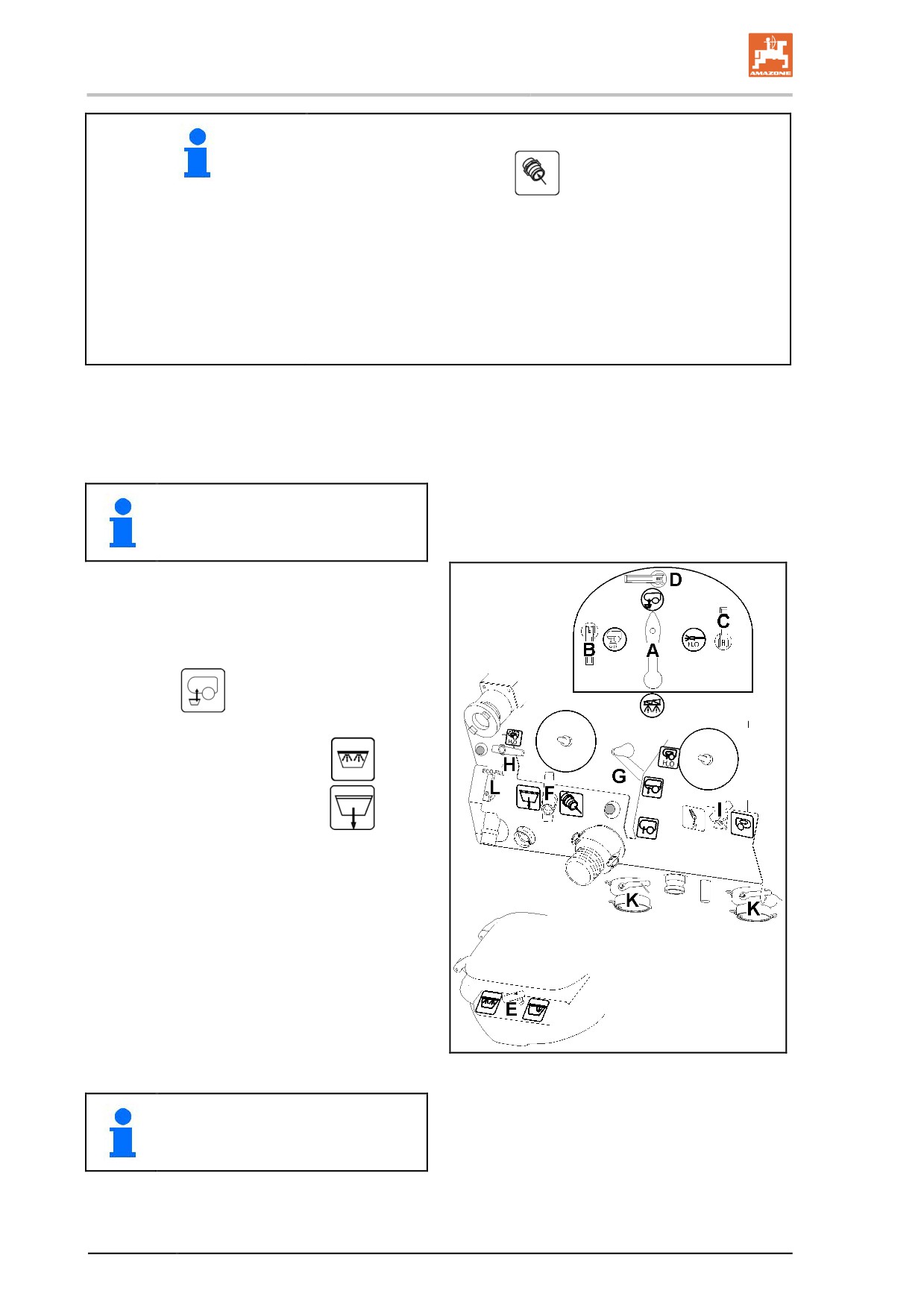
Increasing the suction power by cutting in the injector:
Move switch tap F to position
Only switch the injector on as well once the pump has drawn in the
water.
•
The water being sucked via the injector does not flow through
the suction filter.
•
Comfort equipment with filling stop:
The additional injector must not be switched on, as the automatic
filling stop will not function otherwise.
4. Start blending in the agent once 20% of the
tank filling level has been reached.
Blending in the agent:
Blending in the agent via Ecofill, see
page 156).
5. Open the induction bowl lid.
6. Close switch tap L.
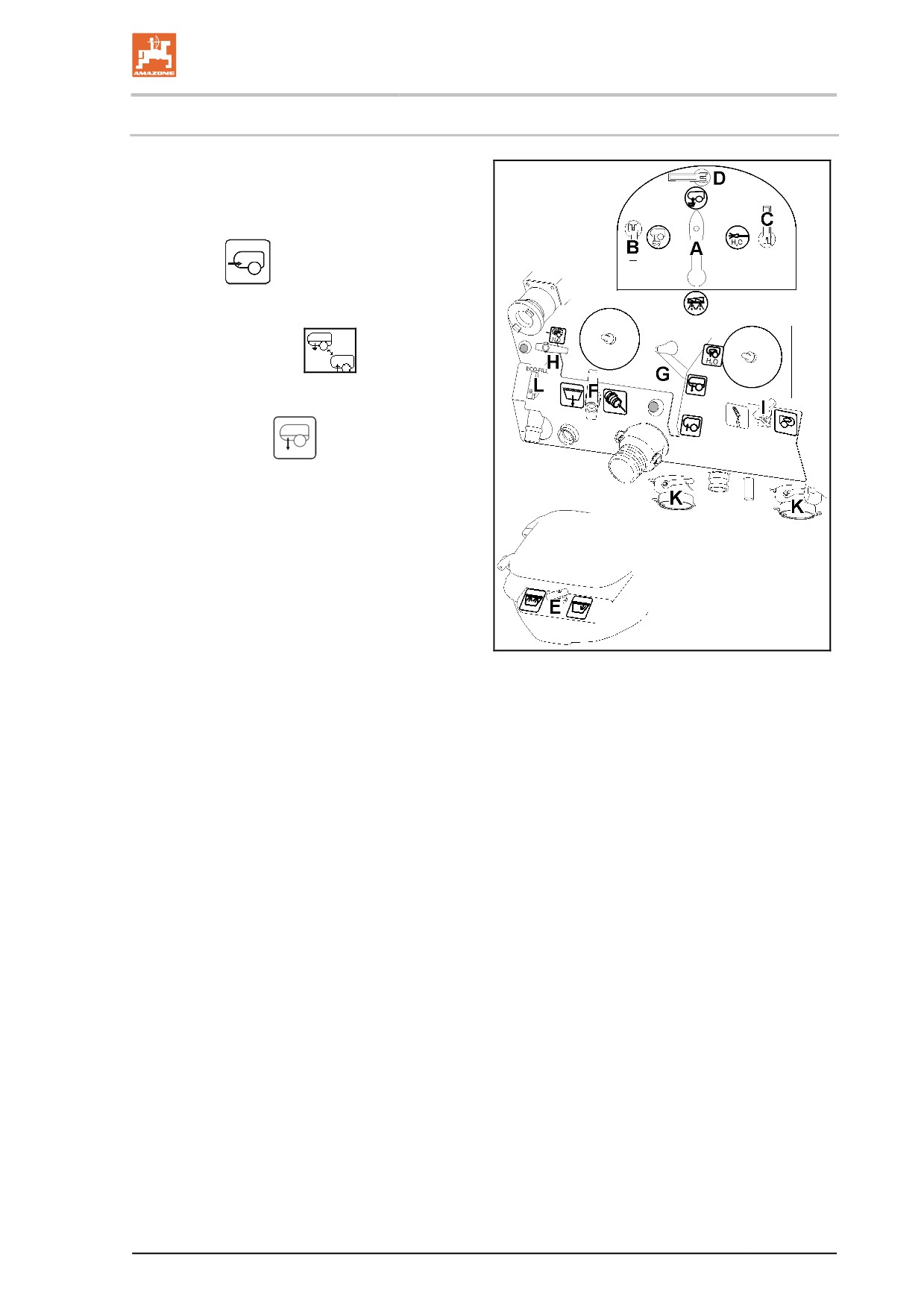
7. Move the pressure gauge switch tap A to
position
8.
Open switch tap D
9. Move switch tap E to position
10. Move switch tap F to position
Fig. 106
While blending in the agent, the supply
of water and the suction speed can be
adjusted using switch taps E and F.
154
Using the machine
11. Pour the quantity of agent calculated and
measured for filling the tank into the induc-
tion bowl.
→ The content of the induction bowl is evacu-
ated.
To increase the user's protection, for
example when handling powder
agents, first pour the agent into the
induction bowl, close the cover and
then dissolve the compound and draw
off the solution.
Rinse the canister:
12. Wash the canister or other containers using
the canister flushing.
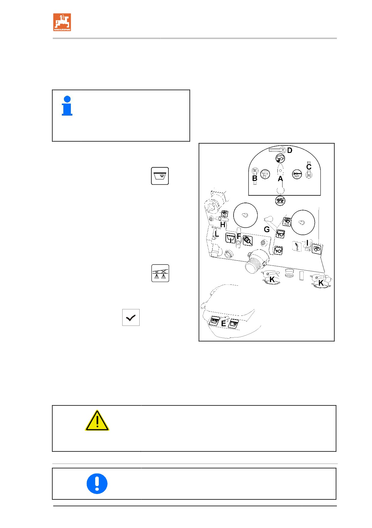
13. Move switch tap E to position
14. Press the canister down for at least 30
secs.
→ The canister is rinsed with water.
15. Move switch tap E to position 0 and re-
move the canister.
16. Move switch tap F to position 0.
17. Close switch tap D.
18. Move switch tap A to position
Once the tank has reached the set filling lev-
el:
19. Operating terminal:
Take value for
the current filling level.
→ After the filling, the intake side is automati-
cally switched over to spraying.
Fig. 107
20. Decouple the suction hose from the filling
connection.
→ The suction hose is still filled with water.
DANGER
The additional injector must not be switched on at the end of the filling
process as otherwise the automatic filling stop will not work.
Set switch tap F to position 0.
Filling from open water access points
Follow regulations closely when filling the spray liquid tank from an
open water access point with a suction hose.
155
Using the machine
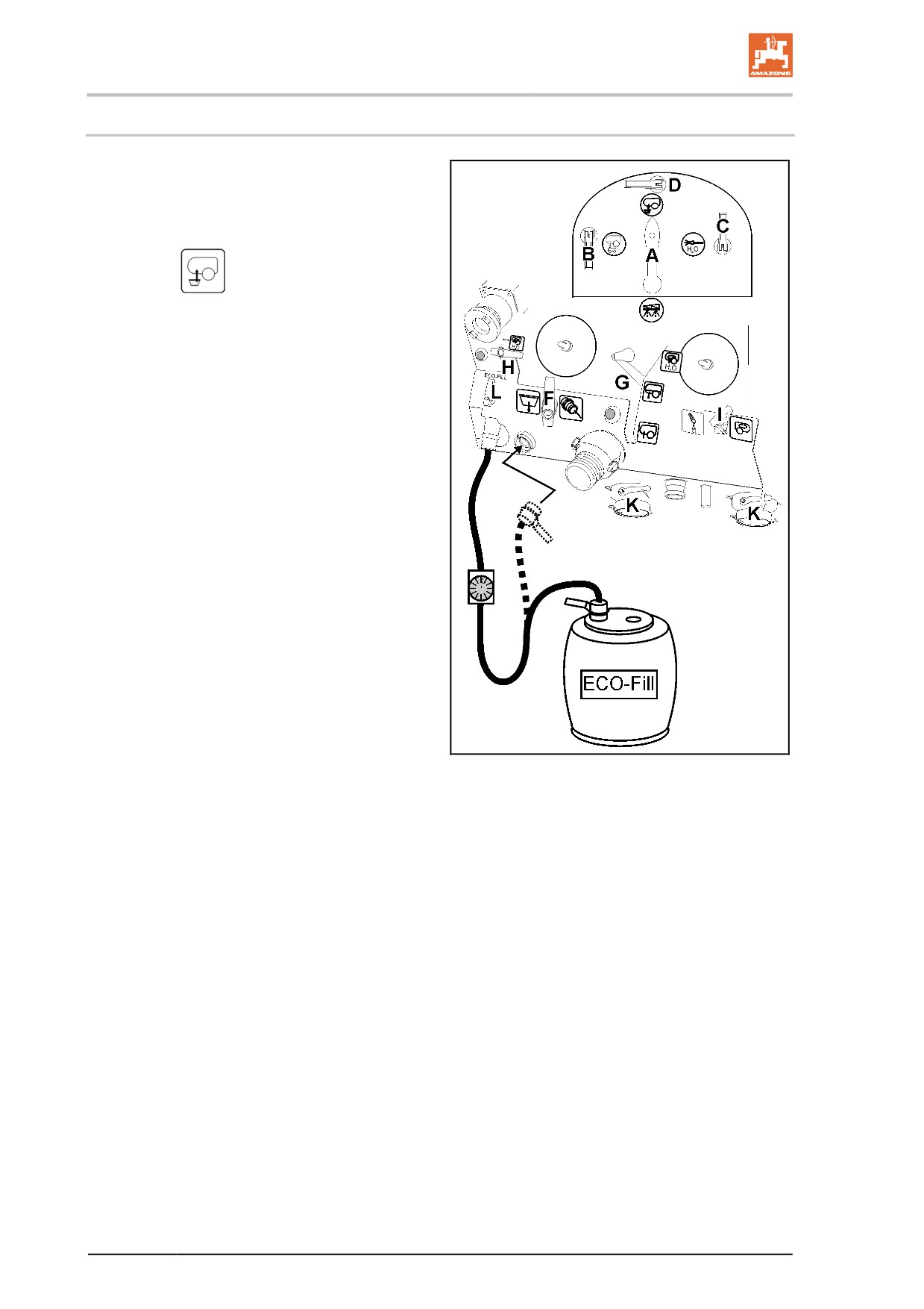
10.2.4 Adding the agent using Ecofill
1. Activate the pump.
2. Couple the Ecofill container with Ecofill
connection.
3. Move the pressure gauge switch tap A to
position
4. Move switch tap D to open.
5. Move switch tap E and F to position 0.
6. Move switch tap L to position 1.
→ Evacuate the Ecofill container.
7. Move switch tap L to position 0 when the
desired quantity has been evacuated from
the Ecofill container.
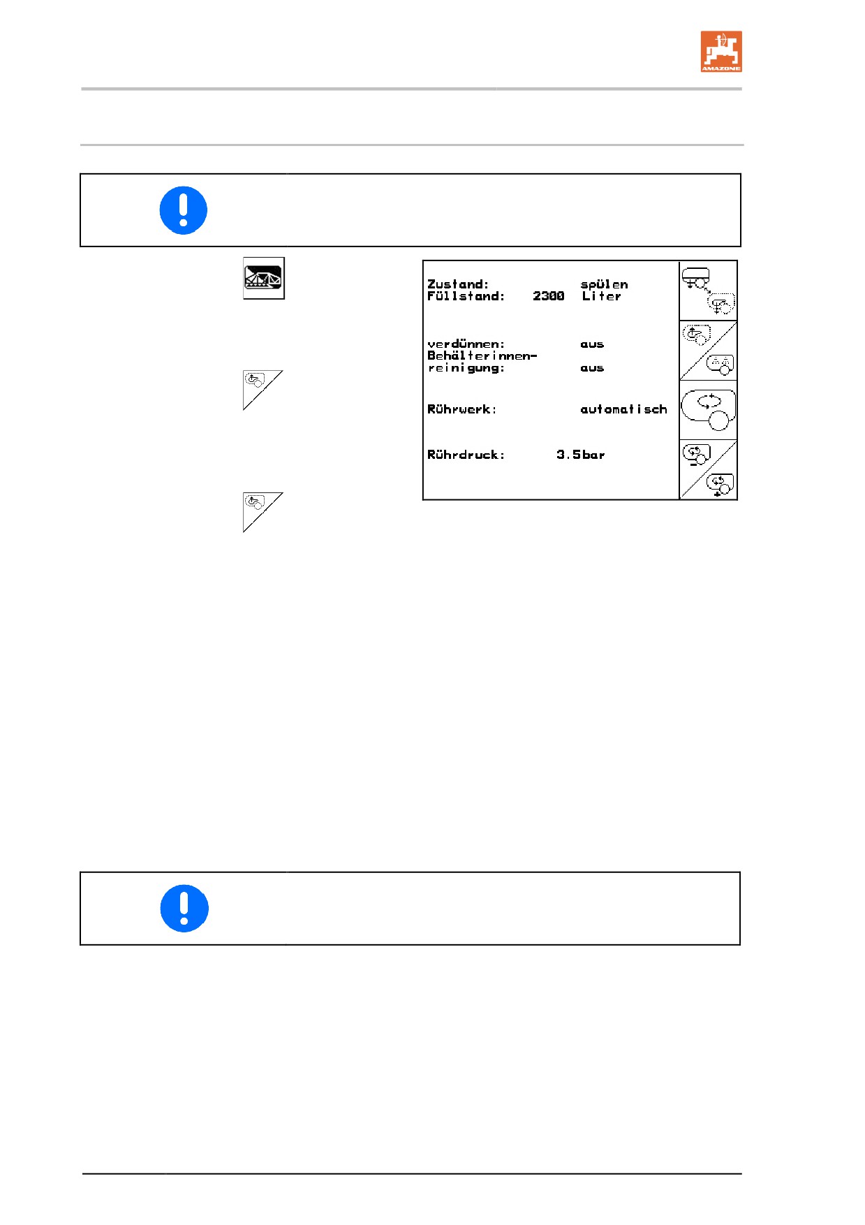
Rinsing the Ecofill counter:
1. Decouple the hose from the Ecofill contain-
er and couple it to the flushing foot.
2. Move switch tap L to position 1.
→ The counter is flushed.
3. Move switch tap L and D back to 0 and
disconnect the counter.
Fig. 108
156
Using the machine
10.2.5 Filling the spray liquid tank via the filling connection and blending in the
agent
In the operating terminal, call up the filling display in the Work menu in
order to enter the re-filling quantity and make use of the automatic
filling stop.
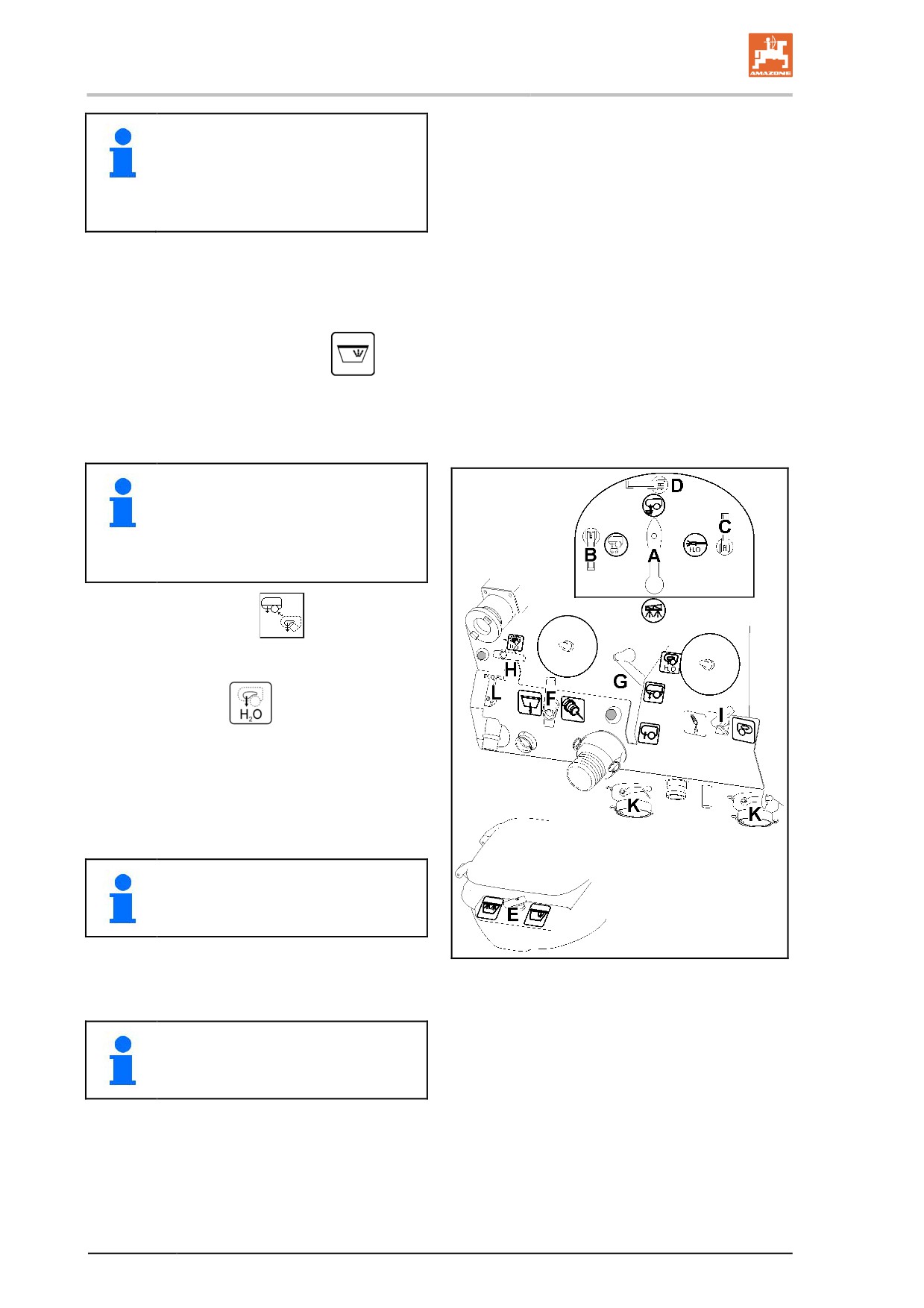
1. Connect the pressure line to the filling con-
nection on the control terminal.
2. Press the pressure filling button on the con-
trol terminal.
→ The tank is filled automatically up the signal
limit.
3. Start blending in the agent once 20% of the
tank filling level has been reached.
Blending in the agents:
(Blending in the agent via Ecofill, see page 156).
4.
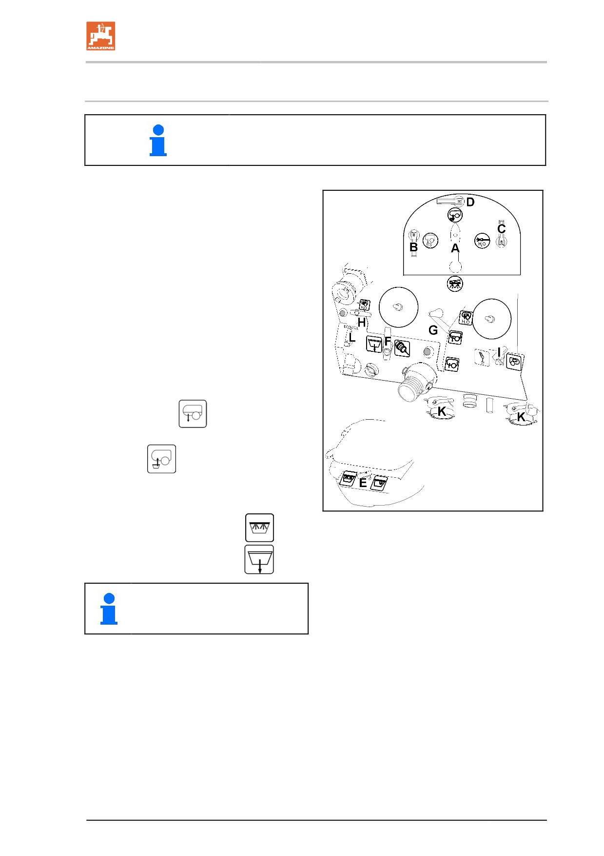
Activate the pump, set the pump speed
to 400 rpm.
5.
Press the suction port button G, suction
port in position
6.
Move the pressure gauge switch tap A to
position
7.
Open switch tap D
8.
Open the induction bowl lid.
Fig. 109
9.
Move switch tap E to position
10.
Move switch tap F to position
While blending in the agent, the supply
of water and the suction speed can be
adjusted using switch taps E and F.
11.
Pour the calculated and measured quantity
of agent for filling the tank into the induction
bowl (maximum 50 l).
→
The content of the induction bowl is evacu-
ated.
157
Using the machine
To increase the user's protection, for
example when handling powder
agents, first pour the agent into the
induction bowl, close the cover and
then dissolve the compound and draw
off the solution.
Rinse the canister:
12. Wash the canister or other containers using
the canister flushing equipment.
Move switch tap E to position
13. Press the canister down for at least 30
secs.
→ The canister is washed with spray liquid.
To flush a number of canisters, flush
them with spray liquid immediately
after they are emptied.
Then wash all canisters with flushing
water one after another.
14. Operating terminal:
Suction port to
suction - flushing water/
Press the suction port button G, suction
port in position
15. Close switch taps D.
16. Press the canister down for at least
30 secs.
The canister is washed with flushing
water.
If spray liquid was previously being
used, it takes a little time before the
flushing water reaches the nozzle.
17. Move switch tap E to position 0 and re-
move the canister.
Fig. 110
18. Open switch tap D.
Due to the high consumption of flush-
ing water, keep switch tap D open only
as long as necessary.
158
Using the machine
19. Move switch tap F to position
→ The content of the induction bowl is evac-
uated.
20. Move switch tap E to position
→ The induction bowl is cleaned
21. Move switch taps E and F to position 0.
22. Close switch tap D again.
23. Move the pressure gauge switch tap A to
position
Once the tank has reached the set filling lev-
el:
→ If the filling level entered in the filling menu
has been reached, the filling process is
terminated automatically.
24. Close the external stop tap on the filling
hose.
25. For pressure relief in the filling hose: press
the button on the control terminal.
26. Uncouple pressure line.
27.
Accept the value for the current fill
level.
159
Using the machine
10.3
Spraying operation
Pay attention to the separate operating manual for the operating ter-
minal.
Special instructions for spraying operations
•
Test the field sprayer by carrying out a calibration:
ο before the start of the season
ο when there are deviations between the actual indicated
spray pressure and the spray pressure prescribed in the
spray table.
•
Before starting to spray, determine the exact spray rate required,
referring to the instructions of the crop protection agent manufac-
turer.
→
Before starting to spray, enter the required spray rate (target
rate) in the control terminal.
•
During spraying operations, adhere exactly to the required spray
rate [l/ha]:
ο in order to achieve the best possible results from your
measure to protect your crop
ο to avoid unnecessary pollution of the environment.
•
Select the required nozzle type from the spray table before start-
ing to spray, taking into account:
ο the prescribed operational speed,
ο the required spray rate and
ο the required atomisation characteristic (fine, medium or
coarse-dropped) of the crop protection agent used in the
crop protection measure.
Refer to the section "Spray tables for flat-fan, anti-drift, in-
jector and air-mix nozzles", page Seite 174.
•
Select the required nozzle size from the spray table before start-
ing to spray, taking into account:
ο the prescribed operational speed,
ο the required spray rate and
ο the targeted spray pressure.
Refer to the section "Spray tables for flat-fan, anti-drift, in-
jector and air-mix nozzles", page Seite 174.
•
Select a low operational speed and a low spray pressure to pre-
vent wastage from windward drift!
Refer to the section "Spray tables for flat-fan, anti-drift, injector
and air-mix nozzles", Seite 174.
•
At wind speeds of 3 m/s, take additional drift reduction measures
(refer to the section "Measures for drift reduction", page 164)!
160
Using the machine
•
Refrain from use if the average wind speed tops 5 m/s (leaves
and thin twigs move).
•
To avoid overdosing, switch the sprayer boom on and off only
while travelling.
•
Avoid overdosing through overlapping, caused by imprecise bout
tracking from one spray path to the next and/or when cornering
on the headlands with the sprayer boom switched on!
•
When increasing operational speed, make sure that the maxi-
mum permissible pump drive speed of 550 rpm is not exceeded!
•
During spraying operations, constantly check the actual spray
liquid consumption in relation to the area treated.
•
Calibrate the flow meter if there are any differences between the
actual spray rate and displayed spray rate.
•
Calibrate the distance sensor (impulses per 100 m) if there are
differences between the actual distance covered and the dis-
tance displayed.
See operating terminal operating manual.
•
If spraying operations must be interrupted because of bad
weather, by all means clean the suction filter, the pump, the
valve chest and the spray lines. See page 169.
•
Spray pressure and nozzle size influence the droplet size and
the volume of liquid sprayed. The higher the spray pressure, the
smaller the droplet diameter of the spray liquid. The smaller
droplets are more easily subject to increased, undesirable drift-
ing!
•
The pump delivery capacity is dependent on the pump drive
speed. Select a pump speed (between 400 and 550 rpm.) that
always allows for an adequate flow rate to the sprayer boom and
the agitator. When selecting, always take into account that more
spray liquid needs to be conveyed at higher operational speeds
and higher spray rates.
•
The agitator normally remains switched on from the filling stage
until the end of spraying operations. The instructions of the agent
manufacturer, however, have priority.
•
The spray liquid tank is empty when the spray pressure abruptly
falls considerably.
•
Residues in the spray liquid tank can be applied correctly up to a
pressure drop of 25%.
•
If the spray pressure drops off while conditions remain otherwise
unaltered, the suction or pressure filter are probably blocked.
161
Using the machine
10.3.1 Applying the spray liquid
•
Properly couple the field sprayer to the tractor!
•
Before starting to spray, check the following machine data on the
operating terminal:
ο the values for the permitted spray pressure range of the
spraying nozzles installed in the sprayer boom
ο the value "impulses per 100 m"
•
Take the appropriate measures if, during spraying operations, a
fault message appears on the display.
•
Check the displayed spraying pressure during spraying opera-
tions.
Make sure that the spray pressure displayed does not, under
any circumstances, deviate by more than ± 25 % from the target
spray pressure given in the spray table by changing, for exam-
ple, the spray rate using the plus / minus buttons. Larger devia-
tions than this from the target spray pressure make it impossible
to achieve the best possible results from your crop protection
measure and lead to pollution of the environment.
Decrease or increase the operational speed until you are back
within the permissible spray pressure range for the target spray
pressure.
162
Using the machine
Example:
Required spray rate:
200 l/ha
Intended operational speed:
8 km/h
Nozzle type:
LU/XR
Nozzle size:
'05'
Permissible pressure range for the in-
min. pressure 1 bar
stalled spraying nozzles:
max. pressure 5 bar
Target spray pressure:
3.7 bar
Permissible spray pressure: 3.7 bar ± 25
min. 2.8 bar and max. 4.6 bar
%
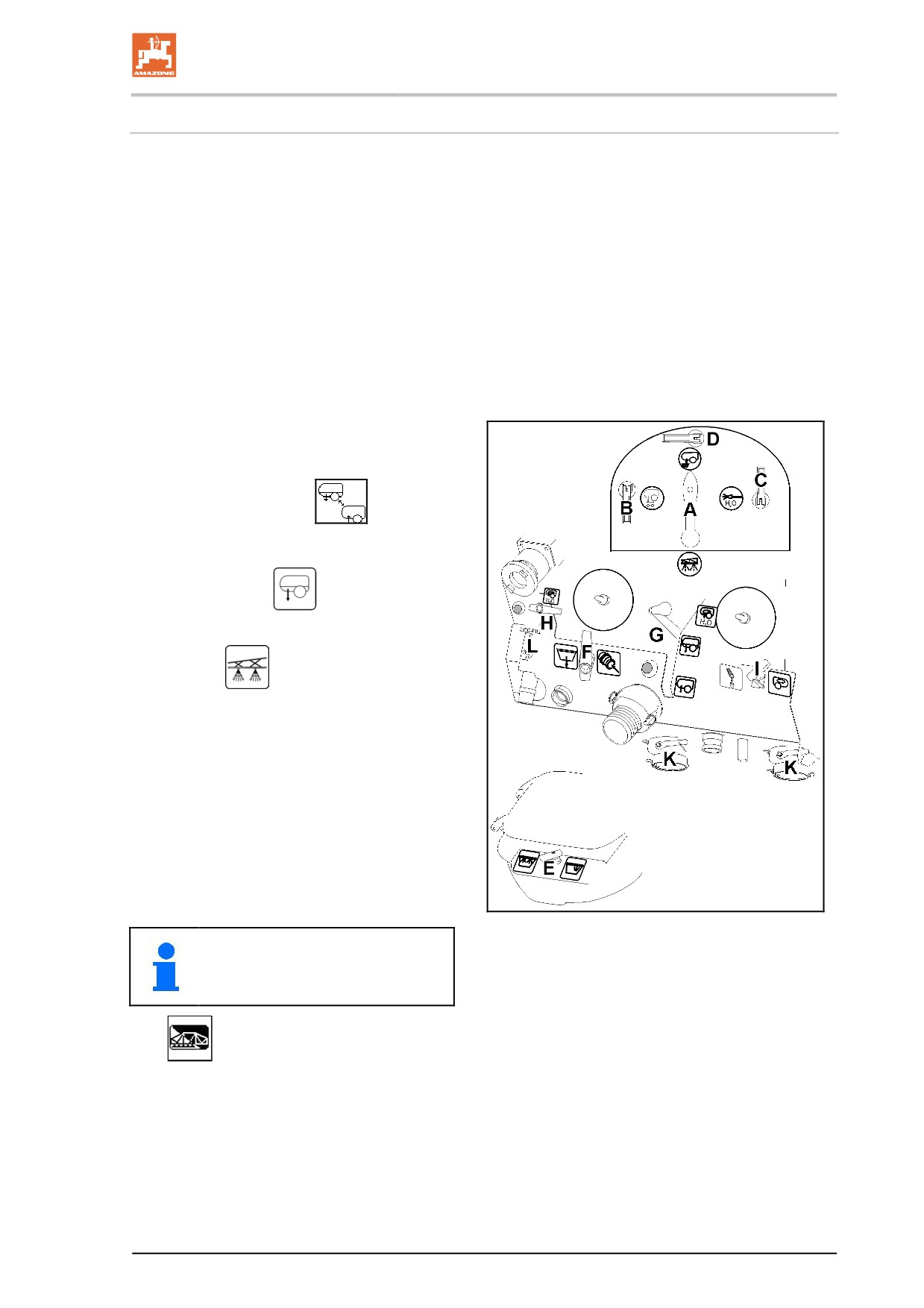
1.
Prepare and stir the spray liquid correctly
in accordance with the instructions from
the crop protection agent manufacturer.
2.
Operating terminal:
Suction
port to spraying /
Press the suction port button G, suction
port in position
3.
Move the pressure gauge switch tap A to
position
4.
Switch on the operating terminal.
5.
Unfold the sprayer boom.
6.
Depending on the nozzles being used,
set the working height of the sprayer
boom (gap between the nozzles and the
crop) according to the spray table.
7.
Enter the value for the required spray
rate into the operating terminal.
8.
Activate pump at the pump operating
speed.
Fig. 111
At low spray rates, the pump speed
can be reduced to save energy.
9.
Switch on the sprayers via the
operating terminal.
163
Using the machine
Driving to the field with the agitator switched on
1. Switch off the operating terminal.
2. Switch off the pump drive.
3. Set the desired agitating intensity.
10.3.2 Drift reduction measures
•
Reschedule treatment for the early morning or the evening hours
(there is generally less wind).
•
Choose larger nozzles and a higher water spray rate.
•
Reduce spray pressure.
•
Precisely maintain the working height of the boom, because the
risk of drifting rises very sharply as the distance between the
nozzles increases.
•
Reduce operational speed (to below 8 km/h).
•
Use so-called anti-drift (AD) nozzles or injector (ID) nozzles
(nozzles which produce a high proportion of coarse drops).
•
Observe the distance requirements of the respective crop pro-
tection agent.
10.3.3 Dilute the spray liquid with flushing water
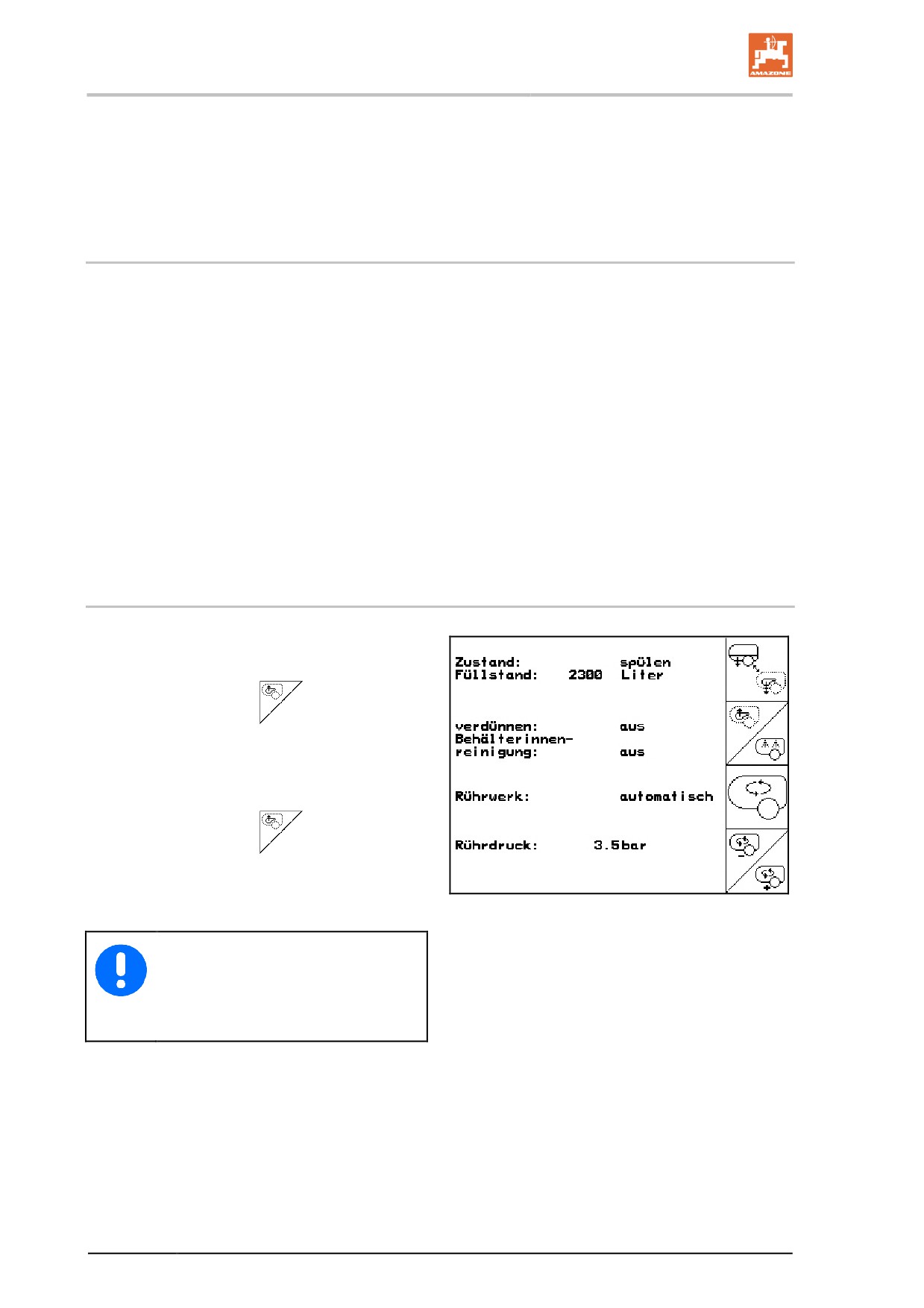
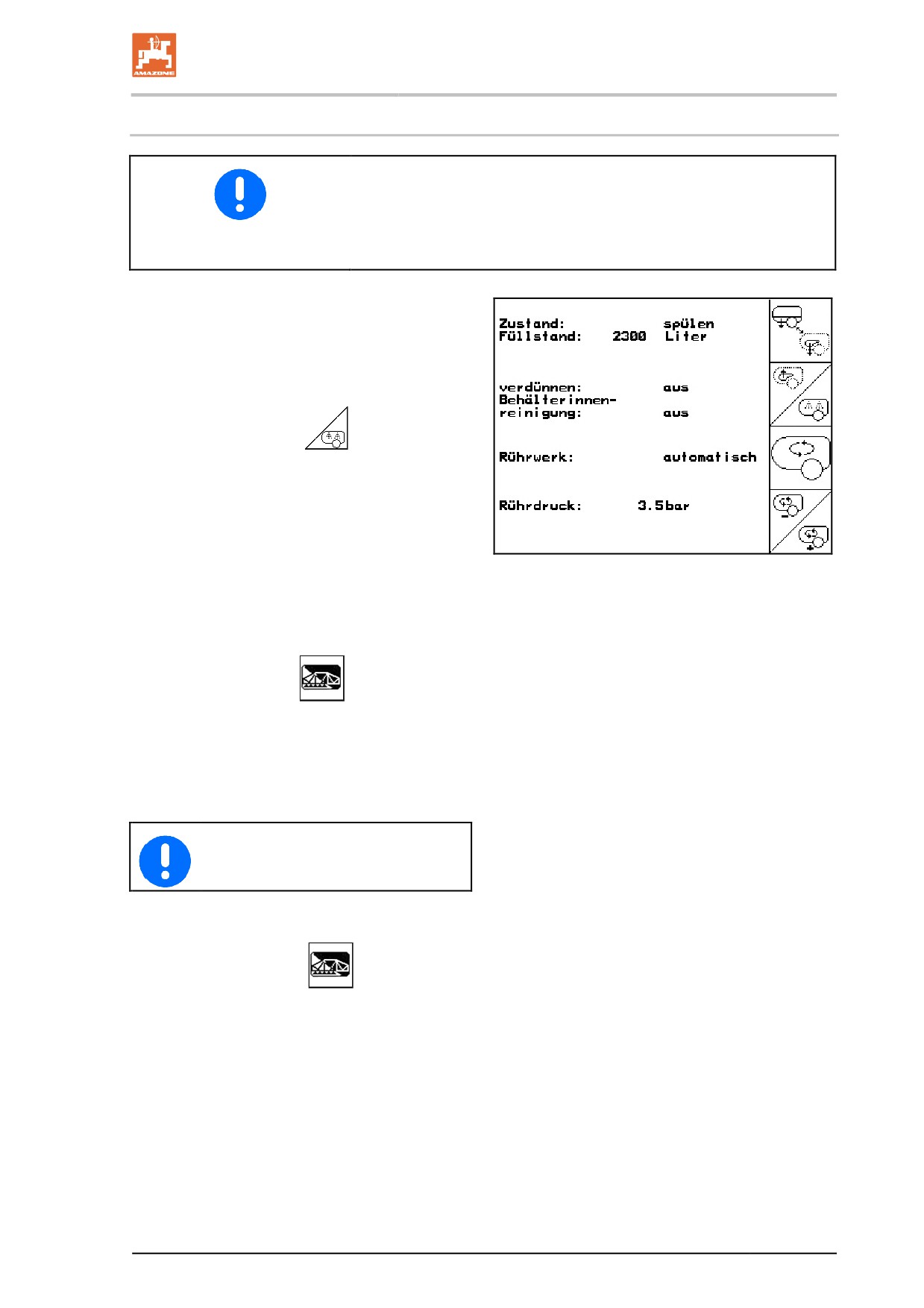
1. Start up pump and set pump speed 450
rpm.
2. Operating terminal:
Start diluting.
→ The flushing water is fed to the container
through the additional agitator.
3. Monitor the container filling level.
4. Operating terminal:
Terminate dilu-
tion.
Fig. 112
In case of a machine with nozzle con-
trol, the spray line is flushed. If you
start spraying again, it will take two to
five minutes before concentrated
spray liquid is applied again.
164
Using the machine
10.4
Residues
There are three types of residue:
•
excessive residue remaining in the spray liquid tank when the
spraying operation is finished
→
This excessive residue is discharged diluted or pumped-out and
disposed of.
•
the technical residue that remains in the spray liquid tank, the
suction chest and the spray line when the spray pressure drops
off by 25%
The suction chest is composed of the suction filter, pump and
pressure controller sub-assemblies. Observe the values for the
technical residues given on page 101
→
This technical residue is discharged diluted onto the field while
cleaning the field sprayer.
•
The final residue that remains in the spray liquid tank, the suc-
tion chest and the spray line after being cleaned with air dis-
charge from the nozzles.
→
This final diluted residue is drained off after cleaning.
Disposing of the residues
•
Make sure that the residue in the spray line continues to be
sprayed in an undiluted concentration. Always spray this residue
on an untreated area. The distance needed to use up this undi-
luted residue can be found in the section "Technical Data - spray
lines", page 101. The residue contained in the spray line is de-
pendent on the sprayer boom working width.
•
Switch on the agitator for spraying the spray liquid tank empty
when the residue in the spray liquid tank is only 5% of the nomi-
nal volume. With the agitator switched on, the technical residue
increases in comparison to the specified values.
•
Measures intended for the user's protection apply when empty-
ing residues. Observe the instructions from the crop protection
agent manufacturer and wear appropriate protective clothing.
Formula for calculating the required distance in [m] for spraying
out the undiluted residue in the spray line:
Undilutable residue [l] x 10,000 [m2/ha]
Required distance [m] =
Application rate [l/ha] x working width [m]
165
Using the machine
10.4.1 Diluting the excess residue in the spray liquid tank and spraying out the di-
luted residue remaining at the end of spraying operations
For machines with comfort equipment, See operating manual for
software ISOBUS.
1.
Operating terminal:
Switch the
sprayer off on the on-board computer.
2.
Activate pump at the pump operating
speed.
3.
Operating terminal:
Start diluting.
→
Use ten-times the volume of flushing water
to dilute the surplus residue.
4.
Monitor the container filling level.
Fig. 113
5.
Operating terminal:
Terminate dilu-
tion.
6.
Switch on the sprayers on the on-board
computer.
→
Where possible, first spray the undiluted
spray liquid out of the spray line onto a re-
maining untreated area.
→
Spray the excess residue onto the already
treated area.
→
Keep spreading the diluted residues until
only air comes out of the nozzles.
7.
Switch off the sprayers on the on-board
computer.
8.
Clean the field sprayer.
When spreading residues on already treated areas, observe the max-
imum permissible spray rate of the agents.
166
Using the machine
10.4.2 Emptying the spray liquid tank using the pump
1. Connect a suitable drainage hose to the
drainage connection on the machine side
using a 2 inch Cam Lock Coupling.
2. Move the pressure gauge switch tap A to
position
3. Open switch tap B.
4. Operating terminal:
Suction port set
to spraying /
Press the suction port button G, suction
port in position
5. Activate the pump (540 rpm).
Fig. 114
167
Using the machine
10.5
Cleaning the field sprayer
•
Keep the exposure time as short as possible, for example by
daily cleaning of the utensils after the spraying operation is com-
pleted. Do not leave the spray liquid in the spray liquid tank for
an excessively long period, e.g. overnight.
The service life and reliability of the field sprayer mainly depend
on how long the materials of the field sprayer are exposed to the
crop protection agent.
•
Clean the field sprayer thoroughly before applying a different
crop protection agent.
•
Carry out the cleaning process on the field where you last car-
ried out the treatment.
•
Carry out the cleaning process using water from the flushing
water tank.
•
You can carry out the cleaning process in the courtyard if you
have a collecting facility installed (e.g. a Biobed).
Observe all national regulations involved.
•
When spreading residues on areas already treated, observe the
maximum permissible spray rate of the agents.
For machines with comfort equipment, See operating manual for
software ISOBUS.
168
Using the machine
10.5.1 Cleaning the sprayer with the tank empty
•
Clean the spray liquid tank on a daily basis!
•
The flushing water tank must be filled completely.
•
The cleaning process should be carried out in a threefold reduc-
tion procedure.
Cleaning:
Condition container filling level < 1 % (empty
container, if possible).
1. Start up pump and set pump speed 450
rpm.
2. Operating terminal:
Start cleaning.
→ Main and additional agitator are flushed, the
inside container cleaning process is
switched on.
→ At a container filling level of 4%, the clean-
ing process is terminated automatically.
→ On machines with nozzle control, the spray
Fig. 115
line is cleaned automatically as well.
Emptying container:
3. Operating terminal:
Switch on spray-
er.
4. Spread the diluted residue on the surface
already treated whilst travelling.
Switch the sprayer on and off at least ten
times whilst travelling.
The valves and return flow hoses are
flushed by switching on and off.
→ Spray out the diluted residue until air is
ejected from the nozzles.
5.
Operating terminal:
Switch off
sprayer.
6. Repeat steps 1 to 3 once or twice.
7. Drain final residue, see page 172172.
8. Clean suction filter and pressure filter; see
page 173, 175.
169
Using the machine
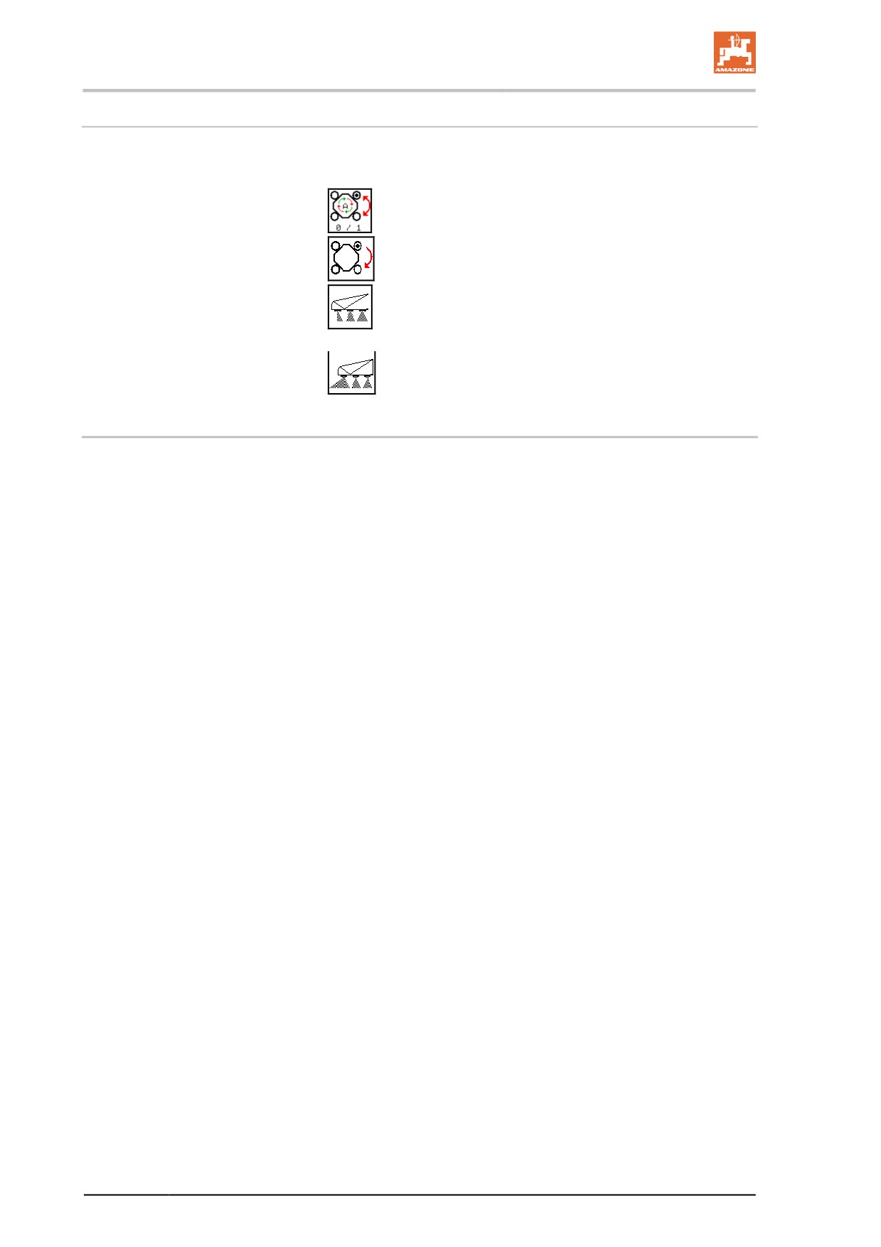
Clean the AmaSelect single nozzle control after each use
To clean the AMASELECT nozzle bodies, all 4 nozzle areas of each
nozzle body must be cleaned.
1.
Set manual nozzle selection.
2.
Flush each nozzle for at least 5 seconds.
3.
Flush the boundary nozzles on each side for at least 5
seconds.
4.
Flush the extra nozzles for at least 5 seconds.
10.5.2
Intensive cleaning of the sprayer during a critical agent change
1. Clean the sprayer in three runs as always, see page 169
2. Fill up flushing water tank.
3. Clean the sprayer, two runs, see page 169.
4. If the sprayer has been previously filled via the pressure con-
nector:
Clean the induction bowl with the spray gun and evacuate the
contents of the induction bowl.
5. Drain the final residue, see page 172.
6. By all means, clean the suction filter and pressure filter, see
page 173, 175.
7. Clean the sprayer, one run, see page 169.
8. Drain the final residue, see page 172.
170
Using the machine
10.5.3 Performing chemical cleaning
•
Chemical cleaning is recommended before critical agent chang-
es and before the implement is decommissioned for a longer pe-
riod of time.
•
Perform the chemical cleaning after the intensive cleaning.
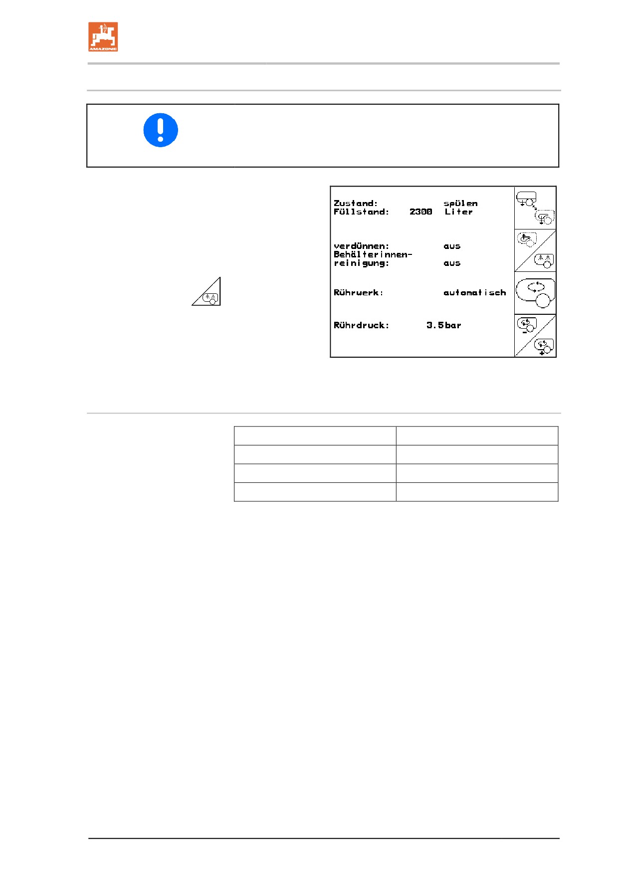
1. Perform an intensive cleaning of the imple-
ment.
2. Run the pump.
3. Fill the spray liquid tank with 100 l of water
and add the cleaning agent according to the
instructions provided by the manufacturer.
4. Control terminal:
Start cleaning.
→ Circulate the mixture in the implement using
the pump (10 minutes).
5. Spray out the mixture on the previously
treated field.
List of available cleaning agents
Product
Manufacturer
Agro-Quick
Adama
JET CLEAR
Sudau agro
Proagro Spritzenreiniger
proagro GmbH
171
Using the machine
10.5.4 Draining the final residues
•
On the field: Spread the final residues over the field.
•
In the courtyard:
ο Place a suitable collecting container under the drain open-
ing of the suction chest and the drain hose for the pressure
filter and collect the final residues.
ο Dispose of the collected spray liquid residue in accordance
with the corresponding legal guidelines.
ο Collect the spray liquid residues in suitable containers.
1.
Switch off the pump.
2.
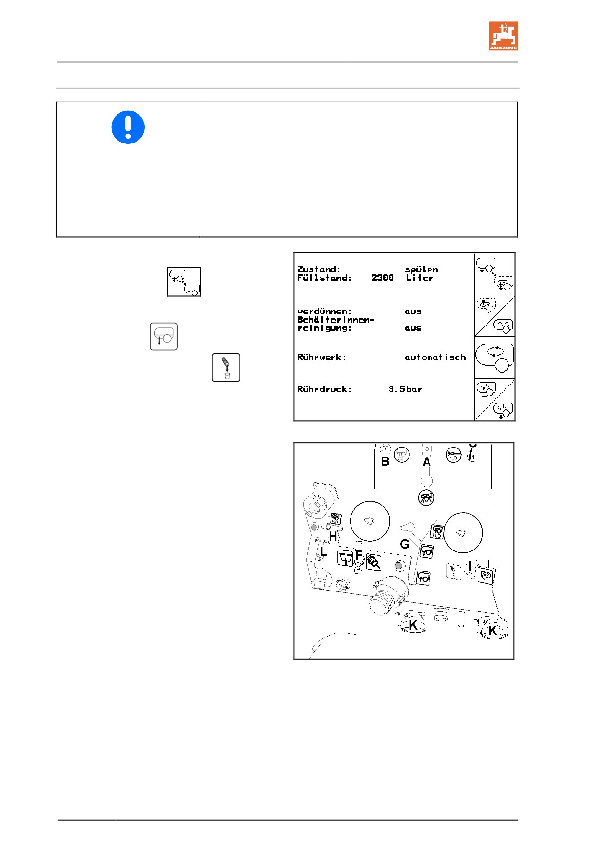
Operating terminal:
Suction port to
spraying /
Press the suction port button G, suc-tion
port in position
3.
Move switch tap I to position
4.
Open stop tap K.
→
Drain the final residue.
Fig. 116
5.
Close switch tap K again and move switch
tap I to position 0.
Fig. 117
172
Using the machine
10.5.5 Cleaning the suction filter when tank is empty
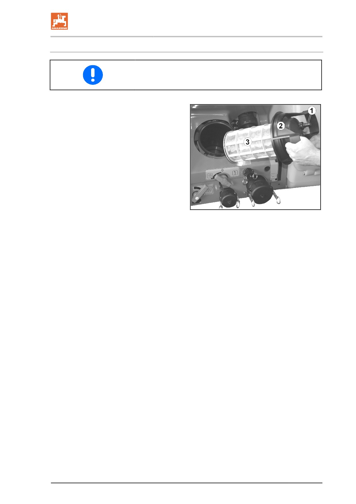
Clean the suction filter (Fig. 122) on a daily basis after cleaning the
field sprayer.
1. Unscrew the cover of the suction filter (Fig.
122/2).
2. Remove the cover with suction filter (Fig.
122/3) and clean with water.
3. Reassemble the suction filter in the reverse
sequence.
4. Check the filter housing for leaks.
Fig. 118
173
Using the machine
10.5.6 Cleaning the suction filter when tank is full
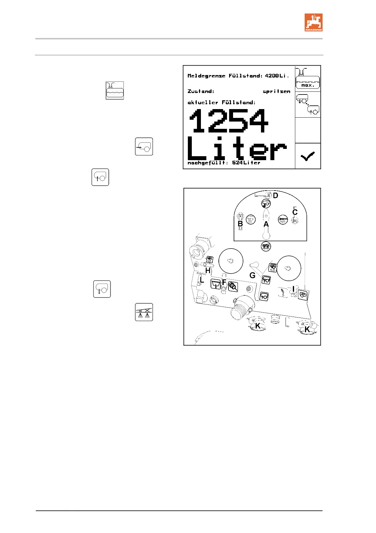
The filling menu has to be called up to clean the
suction filter while the container is full.
1. Operating terminal:
Call up Filling
menu.
2. Activate the pump, adjust pump speed to
300 rpm
3. Place cap on the suction hose coupling..
4. Move switch tap A to position
5. Press the suction port button G, suc-tion
Fig. 119
port in position
→Filter cup is emptied by suction.
6. Unscrew the cover of the suction filter.
7. Activate the relief valve on the suction filter.
8. Remove the cover with suction filter and
clean with water.
9. Reassemble the suction filter in the reverse
sequence.
10. Check the filter cover for leaks.
11. Press the suction port button G, suc-tion
port in position
12. Move switch tap A to position
Fig. 120
174
Using the machine
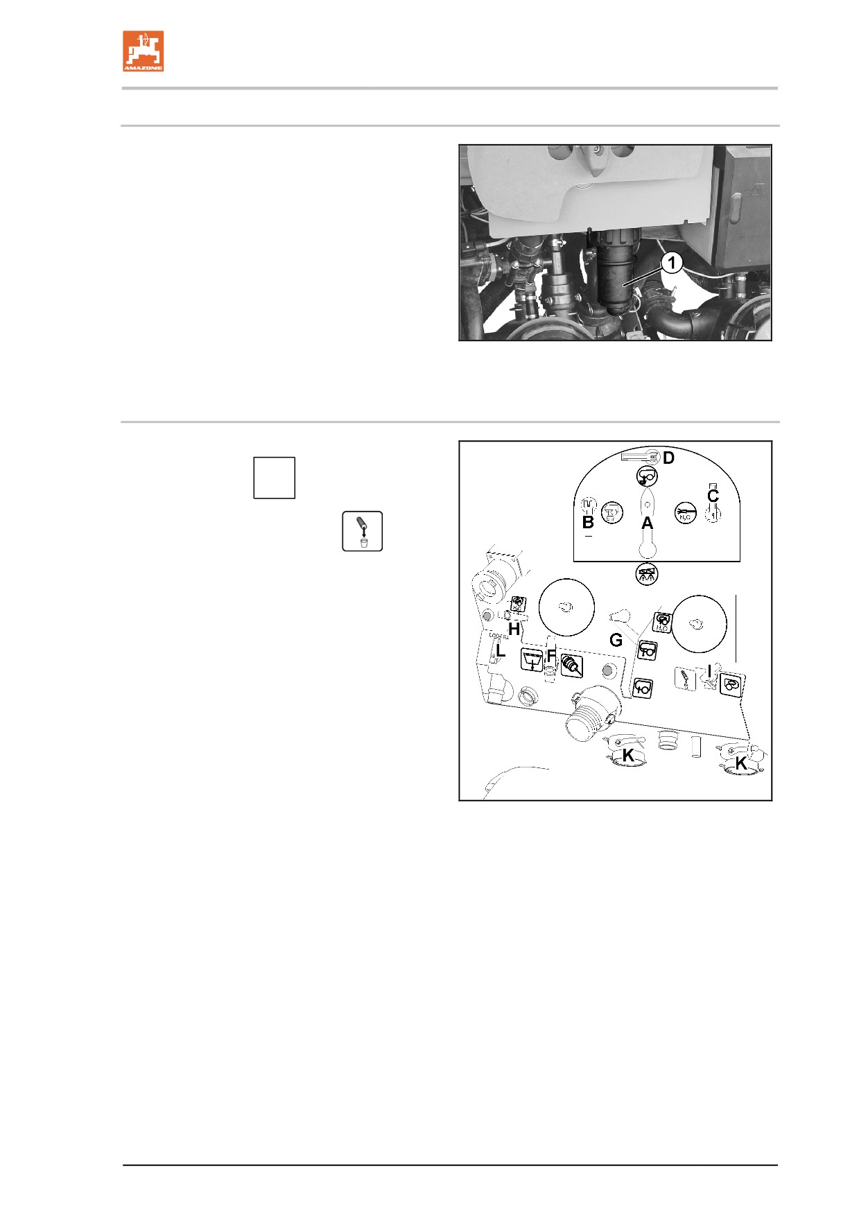
10.5.7 Cleaning the pressure filter when the tank is empty
1. Undo the sleeve nuts.
2. Remove the pressure filter (Fig. 125/1) and
clean with water.
3. Refill the pressure filter.
4. Check the screw connection for leaks.
Fig. 121
10.5.8 Cleaning the pressure filter when the tank is full
1. Press the suction port button G, suc-tion
port in position
2. Move switch tap I to position
→ Drain the residue into the pressure filter.
1. Undo the sleeve nuts.
2. Remove the pressure filter (Fig. 125/1) and
clean with water.
3. Refill the pressure filter.
4. Check the screw connection for leaks.
5. Move switch tap I to position 0.
Fig. 122
175
Using the machine
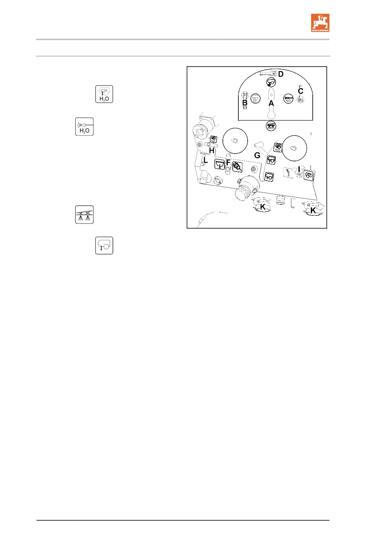
10.5.9 Exterior cleaning
1. Activate the pump.
2. Press the suction port button G, suc-tion
port in position
3. Move the pressure gauge switch tap A to
position
4. Open switch tap C.
5. Clean the field sprayer and the sprayer
boom with the spray gun.
Following the external cleaning:
6. Close switch tap C and
7. Move the pressure gauge switch tap A to
position
8. Press the suction port button G, suc-tion
Fig. 123
port in position
176
Using the machine
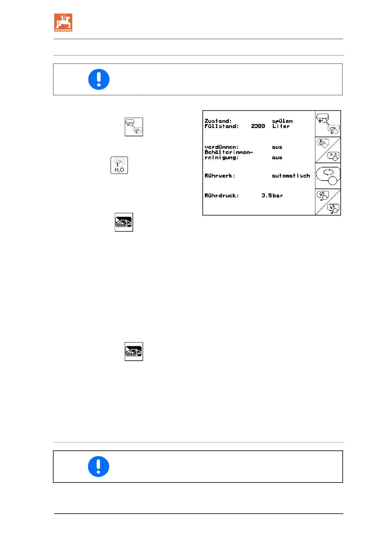
10.5.10 Cleaning the sprayer with a full tank (work interruption)
If spraying operations must be interrupted because of bad weather, by
all means clean the suction chest (suction filter, pumps, pressure
controller) and the spray line.
1. Activate the pump.
2. Operating terminal:
Suction port to
suction - flushing water/
Press the suction port button G, suc-tion
port in position
3. The flushing water is sucked in, close agita-
tors.
Without nozzle control:
Fig. 124
4. Bedienterminal:
Spritzen einschalten
Spread at least 50 litres of flushing water over an
untreated area while driving.
→ The sprayer is cleaned with flushing water.
•
Tank, agitators are not clean!
•
The spray liquid concentration in the
tank is unchanged.
With nozzle control:
→ The sprayer is cleaned with flushing water.
This is done using two litres of flushing wa-
ter per metre of working width (observe the
filling level).
5. Operating terminal:
Switch on the
sprayers for a short period.
→ The nozzles are flushed.
6. Switch the pump off immediately because
the agent concentration drops.
•
Tank, agitators are not clean!
•
The spray liquid concentration in the
tank has changed.
Continuing the spraying operation
Before continuing with the spraying operation, activate the pump for
five minutes at 540 min-1 and switch on the agitators completely.
177
Double Trail
11
Double Trail
DANGER
Risk of accident!
Switch on the road steering mode when travelling on roads !
Angle sensor - trailer hitch coupling
DANGER
Danger of injury caused by steering axles, when the angle sen-
sor linkage is uncoupled and moved whilst the voltage and hy-
draulics supply is still plugged in and the tractor is running.
Always disconnect the power supply first before uncoupling the angle
sensor.
DANGER
Danger of injury when working in the area of the trailer coupling.
Do not put any load on the angle sensor linkage.
Before starting to move, please check that the linkage is not bent in
the wrong way. Bent linkage causes incorrect straight travel and
wrong steering angles.
DANGER
Before starting to move, please make sure that the angle sensor
and also the voltage and hydraulics supply are connected up
correctly! Monitor the steering system fault signals within the
first few metres travelled.
11.1
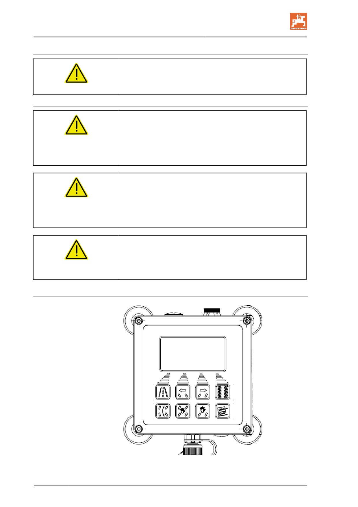
Operating terminal
Fig. 125
178
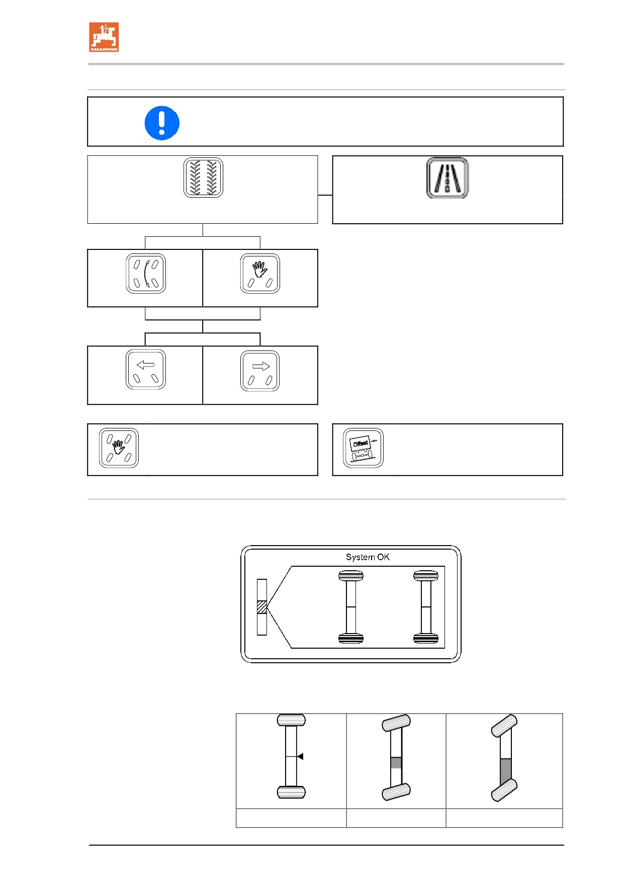
Double Trail
Buttons
The steering program selected is indicated by the corresponding but-
ton lighting up.
Field steering mode (all-wheel steering system)
Road steering mode (rear axle steers)
Automatic operation
Manual operation
Axle to the left
Axle to the right
Without function
Field mode steering program:
Crab steering system
Graphics display
The real steering value of each steered axle is displayed by symbols
in the graphics display.
Fault messages are displayed as fault codes. In addition, the buzzer
is sounded shortly for every new fault and when starting up while
there is a fault condition.
Axle locked
Axle steered
Axle steered maximum
179
Double Trail
11.2
Road use
•
After switching on the steering system, this is in road steering
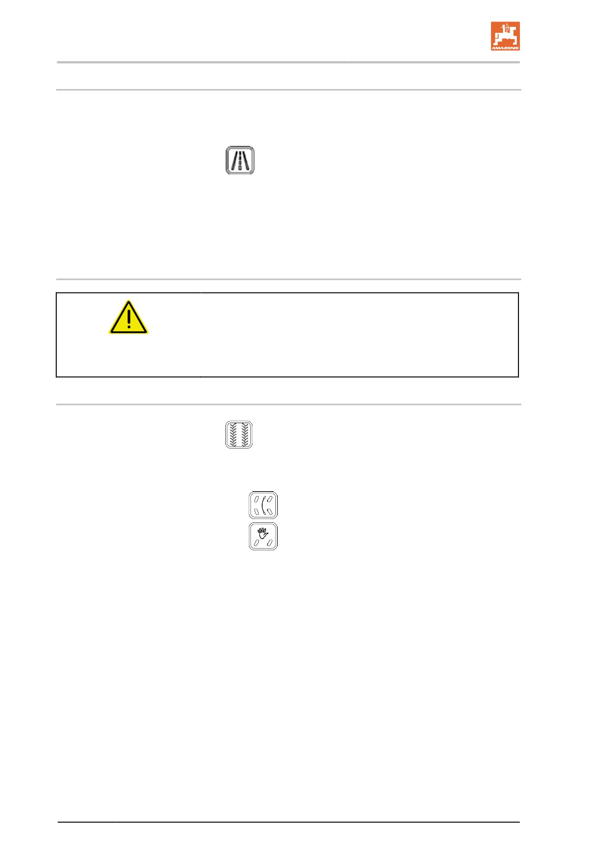
mode as a matter of principle.
•
If the steering system is in field steering mode, pressing the
button will change it to road steering mode.
•
When travelling faster than 20 km/h, the steering system is
switched to road use automatically.
In road use, the front axle is operated as a rigid axle and the rear axle
is steered opposite depending on the ramp angle between the ma-
chine and the tractor.
11.3
Field operation
WARNING
Danger of accident by travelling on roads in field mode.
Field mode with its steering programs is not allowed to be used on
public roads. This mode of operation is used only for keeping in the
tracks crossing fields or for manoeuvring in the yard.
11.3.1
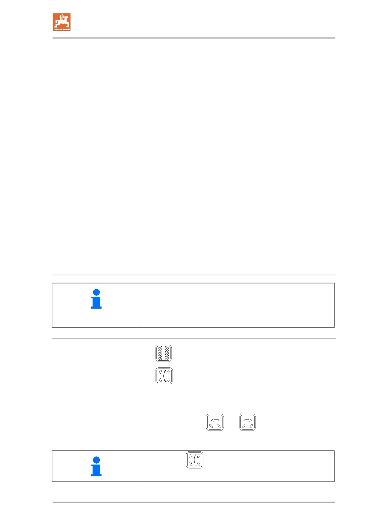
Switching field mode on and off
1.
Press and release the Field mode button.
→ The LED of the button starts flashing.
2. Press the button for the requested steering program:
ο
All-wheel steering on the field
ο
Manual steering for manoeuvring.
→ To highlight what you can choose from, the LEDs of the buttons
of the selectable steering programs are flashing.
→ If after waiting for a short time, no steering program has been
selected, the operating sequence is switched off again automati-
cally. The LED of the field mode button goes off. Field mode has
not been activated.
Activated field mode is indicated by the continuously lit LED of the
field mode button.
180
Double Trail
In the following situations, the steering program button starts flashing:
•
The axles are not located correctly for the steering program
selected.
•
At least one axle has reached its end stop and cannot be moved
any further.
The driver has to watch out because the steering behaviour may
change from now on and steering behaviour may be greatly dis-
torted.
•
The vehicle speed has exceeded the warning threshold for field
mode.
The vehicle is moving in the borderline region to the maximum
vehicle speed permitted in field mode.
Field mode can be switched on only when the following conditions
are met:
•
The machine is at a standstill.
•
The speed signals are fault-free.
•
There is no severe fault.
•
The operating sequence has been carried out correctly.
The field mode is switched off by:
•
actuating the road button.
•
automatic switch off when the permissible travelling speed is
exceeded.
•
the steering system is switched on and off.
Switching between the steering programs
Within the field mode, up to a slow travelling speed, you can switch
between steering programs.
When switching over whilst travelling, the axle system is synchro-
nised automatically.
11.3.2 Steering program - track following steering system
1.
Press the field mode button.
2.
Press the track following steering mode button.
→ This steering program is used to travel in a geometric shape,
where the machine follows the tractor in the same track as far as
possible.
The additional buttons
and
can be used to provide an
offset for the setpoint axle angle. Thus, the track following steering
system can counteract the drift on sloping ground.
By pressing the
button again, the offset is reset again.
181
Double Trail
11.3.3 Steering program - manual operation
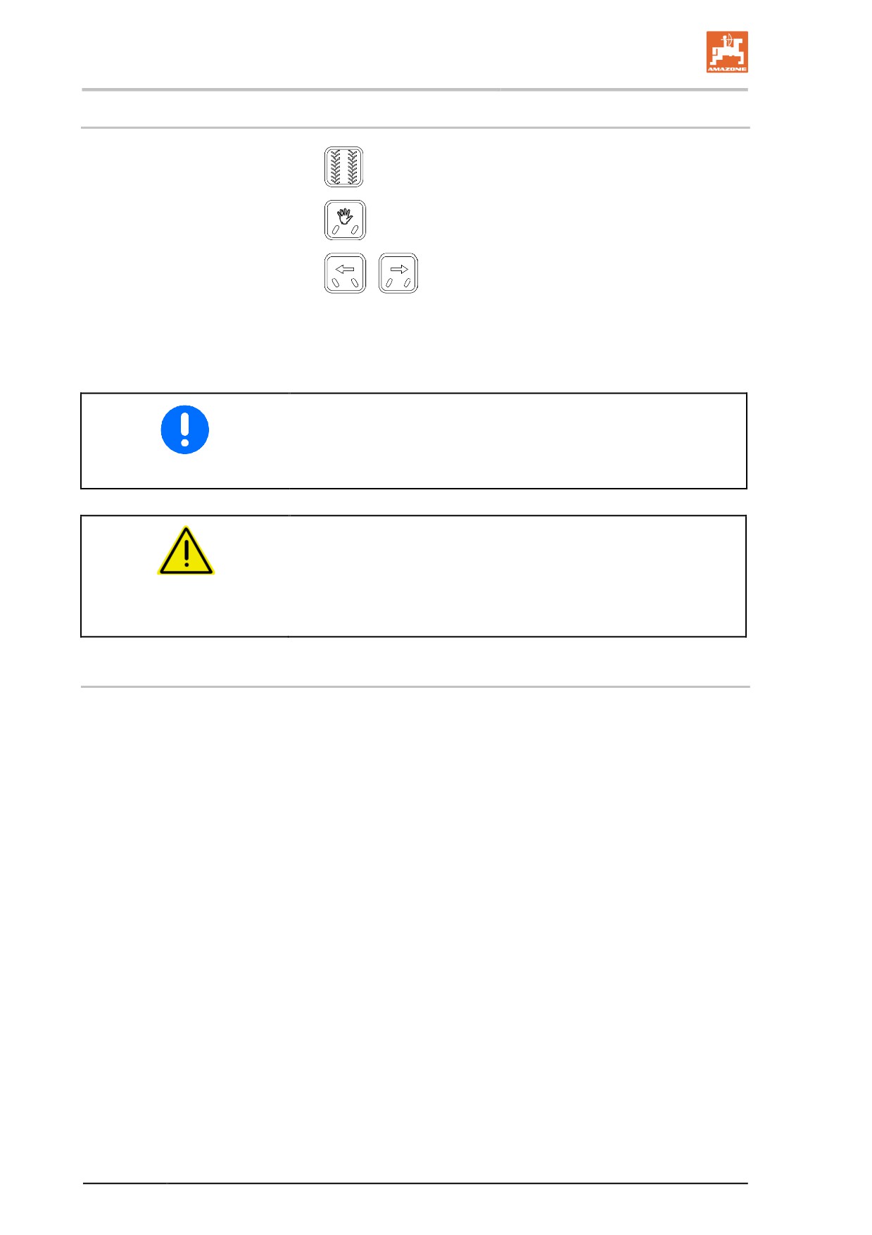
1.
Press the field mode button.
2.
Press the manual operation button.
3.
/
Press the button to manually achieve the re-
quested steering angle.
→ This steering program is used primarily for manoeuvring in the
yard.
In the process, the direction of the arrow corresponds to the steering
direction of the tractor in the direction of travel.
For the driver, this function appears as a direct control of the steered
axles as he has specified.
WARNING
Danger of accident caused by simultaneous and counter-acting
dependency of ramp angle and manual offset on the steering
angle.
The offset should be used with the greatest of care.
11.4
Axle synchronisation
When the operating condition of the steering system is changed, it is
possible that the steered axles may not be in the geometrically cor-
rect position. The initial steering of the axles to reach the correct posi-
tion is referred to as axle synchronisation.
Examples of changes in operating conditions:
ο switching the steering system on and off.
ο changing the steering program.
A lower travelling speed is required to carry out the synchronisation of
the axles.
182
Double Trail
11.5
Tests and faults
11.5.1
Startup test
After the steering system has been switched on, the steering system
carries out a test of the lamps and buzzers. All lamps and buzzers are
actuated twice briefly.
The hydraulic valves are tested.
•
The machine has to be in standstill for the startup test.
•
Pay attention to this startup test to identify faults in the steering
system and to be able to remedy them.
11.5.2
Fault lamp and fault buzzer
System incidents are indicated by a fault lamp. Once incidents have
occurred, they generally remain permanently, independently of
whether the reason for the incident still exists. If the vehicle is moving
when the incident occurs, the fault buzzer will also be sounded. The
fault buzzer is also sounded when driving off when a fault is present,
provided no complete failure of the steering computer has occurred.
If the cause of the incident has been remedied and/or is no longer
present, the displays can be reset by switching the steering computer
off and on.
11.5.3
Fault memory
The faults triggered are permanently saved in the EEPROM of the
steering computer. This storage can hold 32 incidents. Each incident
is saved with a fault code.
183
Faults
12
Faults
WARNING
Risk of crushing, shearing, cutting, being caught and/or drawn
in, or impact through
•
unintentional falling of the machine raised using the trac-
tor's three-point linkage.
•
unintentional falling of raised, unsecured machine parts.
•
unintentional start-up and rolling of the tractor-machine
combination.
Secure the tractor and the machine against unintentional start-up and
rolling before eliminating faults on the machine. See page 131.
Wait for the machine to stop before entering the machine danger
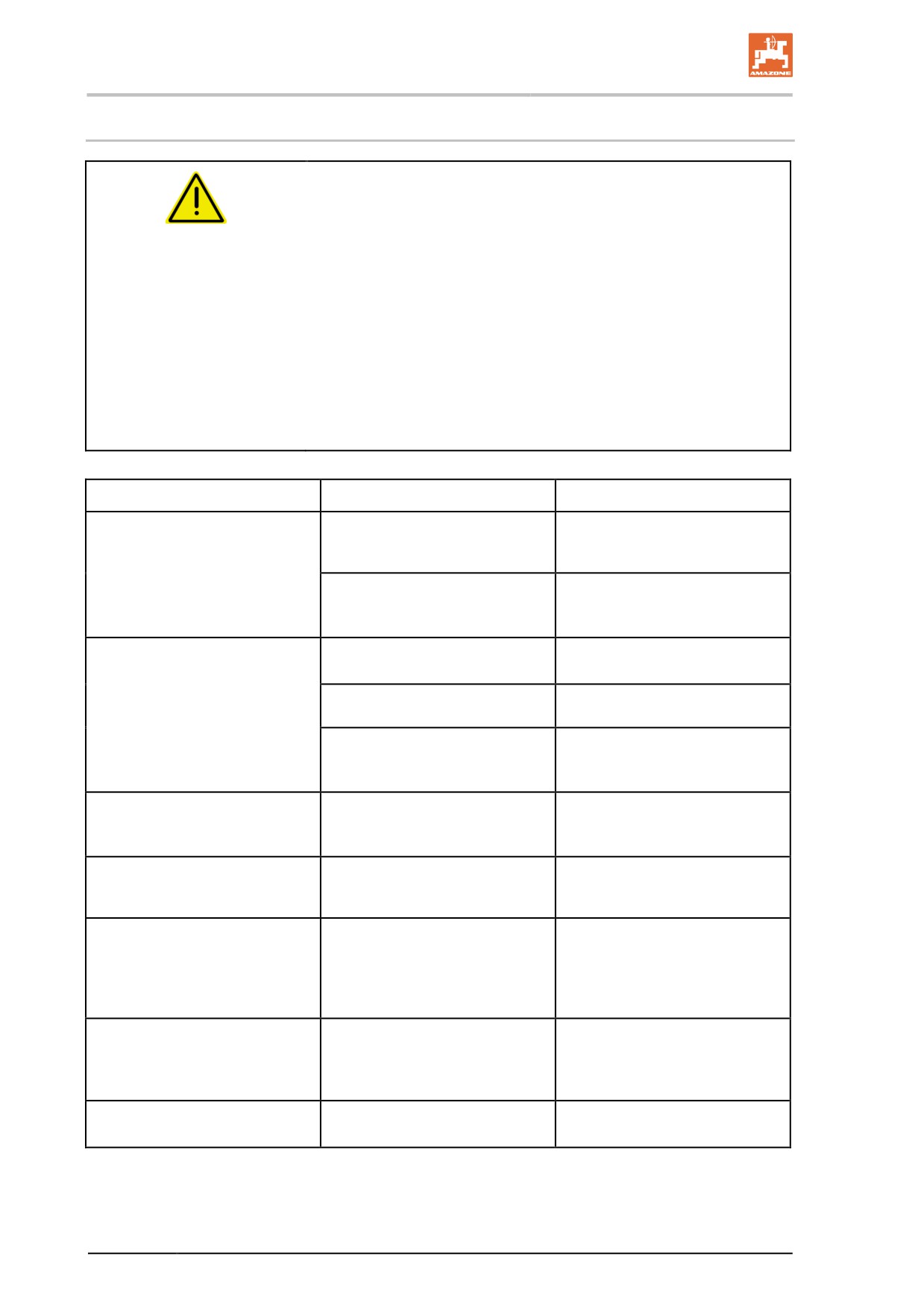
area.
Fault
Cause
Remedy
There is no suction from the
Blockage on the suction side
Remove the blockage.
pump
(suction filter, filter insert, suction
hose).
Pump is sucking in air.
Check the hose connection of the
suction hose (optional) on the
suction port for leak tightness.
The pump does not have any
Suction filter and filter insert dirty.
Clean suction filter and filter in-
power
sert.
The valves are jammed or dam-
Change the valves.
aged.
Pump is sucking in air, recog-
Check the hose connections on
nisable from the air bubbles in
the suction hose for leak tight-
the spray liquid tank.
ness.
The spray cone vibrates
Irregular delivery flow from the
Check, and if necessary replace,
pump.
the suction and pressure-side
valves (see Seite 216).
Oil/spray liquid mixture in the
Pump diaphragm defective.
Change all six piston diaphragms
oil filler neck or clearly visible
(see 217).
consumption of the oil
The required spray rate en-
High operational speed; low
Reduce the operational speed
tered is not achieved
pump drive speed;
and increase the pump drive
speed until the fault message
disappears and the audible alarm
signal stops
There has been a deviation
Deviation from the prescribed
Alter your operational speed to
from the permissible spray
operational speed, which has an
return to the prescribed opera-
pressure range for the nozzle
effect on the spray pressure
tional speed range set for spray-
fitted to the sprayer boom
ing operation
Spray liquid leaking
leaks
close the shut-off valve under the
tank and fix the leak
184
Cleaning, maintenance and repair
13
Cleaning, maintenance and repair
WARNING
Risk of crushing, shearing, cutting, being caught and/or drawn
in, or impact through
•
unintentional falling of the machine raised using the trac-
tor's three-point linkage.
•
unintentional falling of raised, unsecured machine parts.
•
unintentional start-up and rolling of the tractor-machine
combination.
Secure the tractor and machine against unintentional start-up and
rolling, before carrying out cleaning, maintenance or repair work on
the machine; see page 131.
WARNING
Risk of crushing, shearing, cutting, being caught and/or drawn
in, or impact through unprotected danger points.
•
Mount protective equipment removed when cleaning, maintain-
ing and repairing the machine.
•
Replace defective protective equipment with new equipment.
DANGER
•
When carrying out maintenance and repair, observe the
safety instructions, particularly "Field sprayer operation"
section, Seite 36.
•
You may only carry out maintenance or repair work under
moving machine parts that are in a raised position if such
parts are secured with suitable, positive-fit locking devices
against accidental lowering.
Before each start-up
1. Check hoses/tubes and connection pieces for any visually obvi-
ous defects/leaking connections.
2. Repair any areas of chafing on hoses and pipes.
3. Immediately replace worn or damaged hoses and pipes.
4. Immediately repair leaking connections.
185
Cleaning, maintenance and repair
•
Regular and proper maintenance will keep your trailed sprayer in
good condition for a long time, and will prevent early signs of
wear. Regular and proper maintenance is a requirement of our
warranty conditions.
•
Use only genuine AMAZONE spare parts (see "Spare and wear
parts and aids" section, page 18).
•
Use only genuine AMAZONE replacement hoses, and hose
clamps made of V2A for assembly.
•
Specialist knowledge is the requirement for carrying out testing
and maintenance operations. This specialist knowledge is not
given here in this operating manual.
•
Observe environmental protection measures when carrying out
cleaning and maintenance work.
•
Observe legal requirements when disposing of lubricants, e.g.
oils and grease. Also affected by these legal requirements are
parts that come into contact with these lubricants.
•
Do not exceed a greasing pressure of 400 bar when greasing
with high pressure grease guns.
•
The following are prohibited:
ο drilling the running gear.
ο drilling through pre-existing holes on the transport frame.
ο welding load-bearing components.
•
Protective measures are necessary, such as covering lines or
extending lines in particularly critical locations
ο during welding, drilling and grinding work.
ο when working with cut-off wheels near plastic wires and
electric wires.
•
Clean the field sprayer thoroughly with water before carrying out
repair work.
•
Carry out repair work on the field sprayer with the pump
switched off.
•
Thorough cleaning must be carried out before repair work can be
carried out inside the spray liquid tank. Keep out of the spray liq-
uid tank.
•
Disconnect the machine cable and power supply from the on-
board computer when carrying out any cleaning or maintenance
work. This applies especially to welding on the machine.
186
Cleaning, maintenance and repair
13.1
Cleaning
•
Monitor brake, air and hydraulic hose lines particularly carefully
•
Never treat brake, air or hydraulic hose lines with benzin, ben-
zene, petroleum or mineral oils.
•
Lubricate the trailed sprayer after cleaning, particularly after
cleaning with a pressure washer / steam jet, or fat-soluble medi-
ums.
•
Observe the statutory requirements for the handling and removal
of cleaning agents.
Cleaning with a pressure washer / steam jet
•
Always observe the following points when using a pressure
washer / steam jet for cleaning:
ο Do not clean any electrical components.
ο Do not clean any chromed components.
ο Never aim the cleaning jet of the cleaning nozzle of the
high pressure cleaner/steam jet directly at lubrication
points, bearings, rating plates, warning signs, and stickers.
ο Always maintain a minimum jet distance of 300 mm be-
tween the pressure washer or steam jet cleaning nozzle
and the machine.
ο The set pressure of the high-pressure cleaner / steam jet
must not exceed 120 bar.
ο Comply with safety regulations when working with pressure
washers.
187

Cleaning, maintenance and repair
13.2
Winter storage and long periods out of operation
1.
Thoroughly clean the machine prior to overwinter breaks.
ο Cleaning the sprayer with the tank empty, see Page 169.
ο Draining the final residual amount.
2.
Drive the spray pump at low speed and allow the "air to be
pumped" once the flushing process has been completed and liq-
uids no longer run out of the spray nozzles.
3.
Open stop tap K, drain the technical residues of the suction side,
switch several times between the different positions on the suc-
tion fitting G and then close the stop tap K again.
4.
Move the switch tap I in position
, drain the technical resi-
due on the pressure side, switch several times between the dif-
ferent positions on the pressure fitting switch tap A and then
move switch tap I back to position 0.
5.
For each sprayer boom part width section, remove a diaphragm
valve from a nozzle body to allow the nozzle line to run empty.
6.
Switch off the pump drive when liquid no longer runs out of any
section of the nozzle line after changing the positions of the suc-
tion fitting and the pressure fitting several times.
7.
Dismantle and clean the suction filter and the pressure filter.
8.
Dismantle the pressure hose of the pump so that the remaining
water can flow out of the pressure hose and pressure fitting.
9.
Change the positions of the pressure gauge at all positions once
again.
10.
Actuate the sprayer pump for approx. ½ minute until liquid no
longer runs out of the connection on the pressure side of the
pump.
Residual amounts can be sprayed out of the pressure connec-
tion with high pressure.
11. Cover the pump pressure connection to protect it from dirt.
12. Lubricate the universal joint of the universal joint shaft and
grease the profile tubes after longer periods out of operation.
13. Perform an oil change on the pumps before storing for the win-
ter.
14. Drain the hoses on the induction bowl and injector.
15. Empty the flushing water tank by unscrewing the union nut on
the outlet.
•
At temperatures below freezing, hand crank the piston dia-
phragm pumps before starting to prevent residual ice from dam-
aging the piston and piston diaphragm.
•
Store the pressure gauge and any other electronic accessories
in a place where they are safe from frost.
188
Cleaning, maintenance and repair
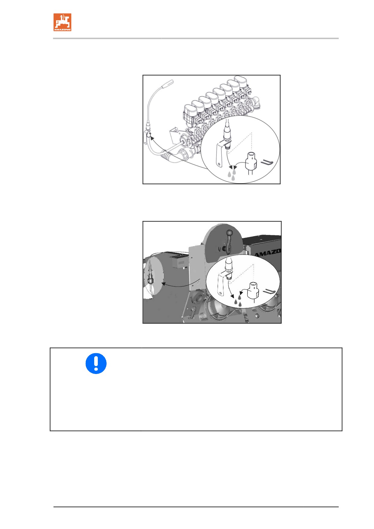
16. Super-L boom: drain the pressure sensor of the boom fitting
with the boom lowered by removing the hose from the pressure
sensor.
Fig. 126
17. Drain the pressure sensor on the main agitator by screwing off
the pressure sensor.
Fig. 127
Before starting up again:
•
Install all of the dismantled parts.
•
Close the suction port drainage tap.
•
At temperatures below freezing, hand crank the piston diaphragm
pumps before starting to prevent residual ice from damaging the
piston and piston diaphragm.
•
Store the pressure gauge and any other electronic accessories in
a place where they are safe from frost!
189
Cleaning, maintenance and repair
13.3
Lubrication specifications
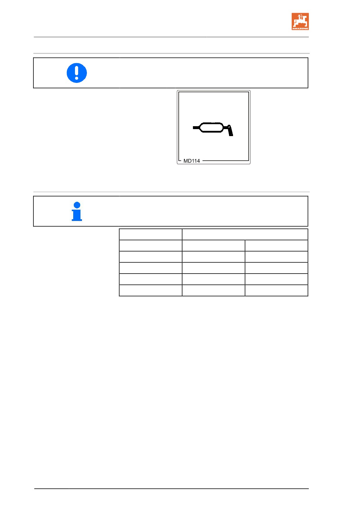
Lubricate all grease nipples (keep gaskets clean).
Lubricate / grease the machine at the specified
intervals.
Lubrication points on the machine are indicated
with the foil (Fig. 132).
Carefully clean the lubrication points and grease
gun before lubrication so that no dirt is pressed
into the bearings. Press the dirty grease out of
the bearings completely and replace it with new
grease.
Fig. 128
Lubricants
For lubrication, use a lithium saponified, multipurpose grease with EP
additives:
Company
Lubricant designation
Normal use conditions
Extreme use conditions
ARAL
Aralub HL 2
Aralub HLP 2
FINA
Marson L2
Marson EPL-2
ESSO
Beacon 2
Beacon EP 2
SHELL
Retinax A
Tetinax AM
190
Cleaning, maintenance and repair
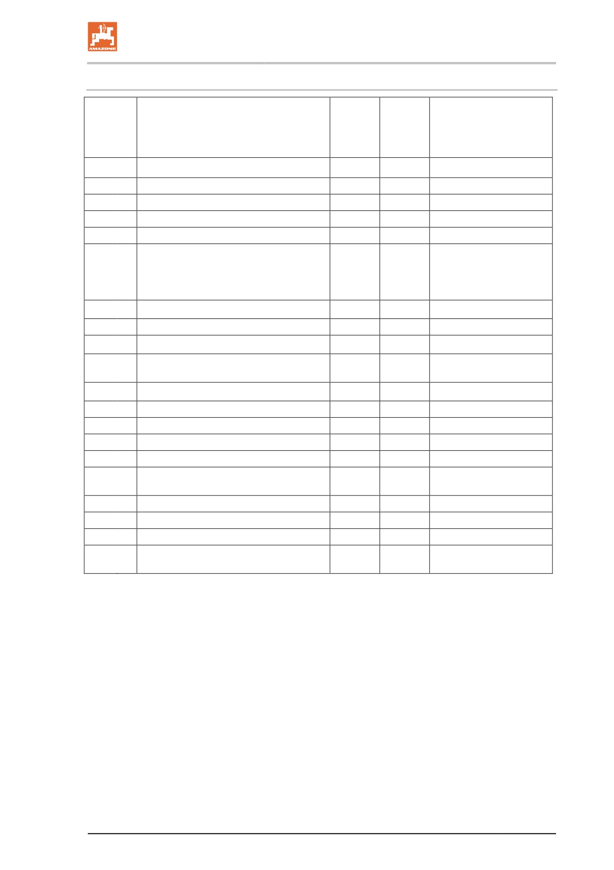
13.3.1 Lubrication point overview
Lubrication point
Interval
Number
Type of lubrication
[h]
of lubri-
cation
points
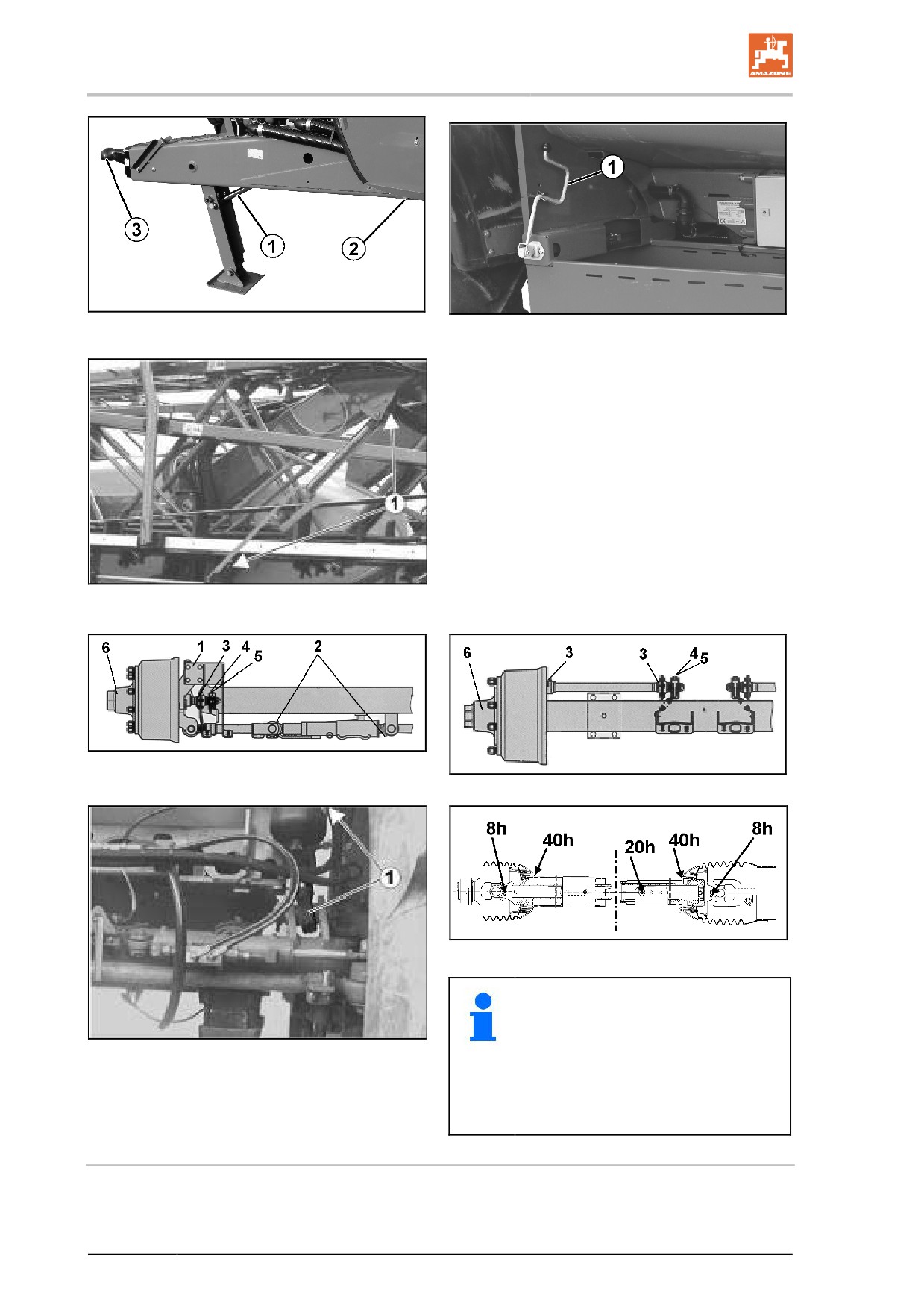
Fig. 133
1
Hydraulic cylinder for stand
100
2
Grease nipple
2
Drawbar bearing
50
2
Grease nipple
3
Towing eye
50
1
Grease
Fig. 134
1
Parking brake
100
1
Grease the cables and
guide rollers.
Grease the spindle using
the grease nipple.
Fig. 135
1
Lifting cylinder
100
4
Grease nipple
Fig. 138
1
Hydraulic cylinder for the hydropneumat-
100
4
Grease nipple
ic suspension
Fig. 139
PTO shaft
5
Grease nipple
Fig. 136
Following steering axle
Fig. 137
Standard axle
1
King pin bearing, upper and lower
40
Grease nipple
2
Steering cylinder heads on steering
200
Grease nipple
axles
3
Brake shaft bearing, outer and inner
200
Grease nipple
4
Linkage adjuster
1000
Grease nipple
5
ECO-Master automatic linkage adjuster
1000
Grease nipple
6
Renew wheel hub bearing grease,
1000
Grease nipple
check taper roller bearings for wear
191
Cleaning, maintenance and repair
Fig. 129
Fig. 130
Fig. 131
Fig. 132
Fig. 133
Fig. 135
•
For winter operation, grease the
protective tubes to prevent them
from freezing.
Fig. 134
•
Also observe the installation and
service instructions from the PTO
shaft manufacturer, which are fas-
tened to the PTO shaft.
Steering cylinder heads on steering axles
In addition to the lubrication work, you must also make sure that the
steering cylinder and the supply line are always bled.
192
Cleaning, maintenance and repair
Brake shaft bearing, outer and inner
Caution: no grease or oil should be allowed to get into the brakes.
Depending on the model series, the cam bearing for the brakes may
not be sealed.
Only use lithium saponified grease with a dropping point greater than
190 °C.
ECO-Master automatic linkage adjuster
Each time the brake linings are replaced:
1. Remove the rubber stopper cap.
2. Apply grease (80 g) until sufficient clean grease escapes at the
adjusting screw.
3. Slacken the adjusting screw by approximately one turn with a
ring spanner. Actuate the brake lever several times by hand.
4. The automatic readjustment should function smoothly. Repeat
several times, as necessary.
5. Refit the stopper cap. Grease again.
Renewing the wheel hub bearing grease
1.
Jack up the vehicle securely and release the brakes.
2.
Remove the wheels and dust caps.
3.
Remove the lynch pin and unscrew the axle nut.
4.
Use a suitable extraction device to remove the wheel hub and
brake drum, taper roller bearing and sealing elements from the
axle stub.
5.
Label the removed wheel hubs and bearing cages so that you do
not confuse them when refitting.
6.
Clean the brakes, check for wear, sound condition and function
and replace worn parts.
The interior of the brake must be kept free from lubricants and
dirt.
7.
Thoroughly clean the interior and exterior of the wheel hubs.
Remove all traces of old grease. Thoroughly clean the bearings
and seals (diesel oil) and check for reusability.
Before refitting the bearings, lightly grease the bearing carrier
and then refit all parts in the reverse order. Carefully fit parts with
press fits and pipe bushings so that they are not twisted or dam-
aged.
The bearings, the wheel hub cavity between the bearings and
the dust cap must be smeared with grease before fitting. The
grease should fill approximately a quarter to a third of the space
in the fitted hub.
8.
Fit the axle nut and adjust the bearing and brake. Finally, carry
out a function check and an appropriate test run and rectify any
detected faults.
The wheel hub bearing must only be greased with BPW special
longlife grease with a dropping point greater than 190 °C.
The wrong grease or too great a quantity can result in damage.
Mixing lithium-saponified grease with sodium-saponified grease can
result in damage caused by incompatibility.
193
Cleaning, maintenance and repair
13.4
Maintenance schedule - overview
•
Carry out maintenance work when the first interval is
reached.
•
The times, continuous services or maintenance intervals of
any third party documentation shall have priority.
After the first working run
Maintenance work
see
Component
Specialist workshop
page
Wheels
•
Wheel nut check
204
X
Hydropneumatic sprung
•
Check if the screws are mechan-
207
suspension
ically secure.
Trailer hitch
•
Check if the screws are mechan-
207
ically secure.
Hydraulic hose lines
•
Check for leak tightness
208
Pumps
•
Check the oil level
215
On a daily basis
Component
Maintenance work
see
Specialist workshop
page
Fluid filter (Profi-folding)
211
•
Check the clogging indicator
If necessary, replace
X
Spray liquid tank
187
Line filter in the nozzle lines
223
•
Clean and/or flush
(if present)
Spraying nozzle
222
Air reservoir for the air brake
•
Drain
209
Every week/ 50 operating hours
Component
Maintenance work
see
Specialist workshop
page
Hydraulic hose lines
•
Check for defects
208
X
•
Check for leak tightness
Wheels
•
Chec k the air pressure.
204
•
Check for damage, deformation
206
Coupling device
and cracks
194
Cleaning, maintenance and repair
Every three months / 200 operating hours
Component
Maintenance work
see
Specialist workshop
page
Dual-circuit service brake
•
Check for leak tightness
201
X
system
•
Check pressure in the air reser-
voir
•
Check brake cylinder pressure
•
Visual inspection of brake cylin-
der
•
Joints on brake valves, brake
cylinders and brake linkages
•
Linkage adjuster brake settings
199
X
•
Brake pad check
X
Wheels
•
Check play on wheel hub bear-
198
X
ings
Line filter
•
Clean
223
•
Replace damaged filter inserts
Hydropneumatic sprung
•
Check if the screws are mechan-
207
suspension
ically secure
Parking brake
•
Check the braking effect with the
203
brake on
Booms
•
Checking the boom for cracks /
beginning of crack formation
Coupling device
•
Check the fastening bolts for
206
wear and tight fit
195
Cleaning, maintenance and repair
Annually / 1,000 operating hours
Component
Maintenance work
see
Specialist workshop
page
Pumps
•
Oil change every 500 operating
215
X
hours
•
Check valves and, if necessary,
216
X
replace
•
Check the piston diaphragm and,
217
X
if necessary replace
•
Check the pressure membrane,
218
X
replace if required
Flow meter and return flow
•
Calibrate the flow meter
218
meter
•
Align the return flow meter
Nozzles
•
Calibrate the field sprayer and
222
check the lateral distribution; if
necessary, replace worn nozzles
Brake drum
•
Check for dirt
198
X
Wheels
•
Wheel nut check
204
X
Brake
Automatic linkage adjuster
199
X
•
Check for function
•
Brake settings
X
Hydraulic system
•
Check the pressure reservoir
208
X
As necessary
Component
Maintenance work
see
Specialist workshop
page
Super-L boom
•
Correct the settings
213
211
solenoid valves
•
Cleaning
Hydraulic throttle valve
•
Adjust the actuation speed
213
Drawbar
•
Replace worn parts
182
Hydraulic plug
•
Rinse / exchange the filter in the
212
hydraulic plug
196
Cleaning, maintenance and repair
13.5
Axle and brake
For optimum brake performance with a minimum of wear, we recom-
mend that the brakes on the tractor are balanced with those on the
trailed sprayer. After the service braking system has been run in for a
suitable period, arrange for the brakes to be balanced by a specialist
workshop.
Have the balancing process carried out before these empirical values
are reached if you discover excessive wear on the brake pads.
To avoid problems with the brakes, adjust all vehicles in accordance
with EC Directive 71/320 EEC.
WARNING
•
Repair and adjustment work on the service braking system
should only be carried out by trained specialist personnel.
•
Special care is required for welding, torch cutting and drill-
ing work in the vicinity of brake lines.
•
Always carry out a braking test after any adjusting or repair
work on the braking system
General visual inspection
WARNING
Carry out a general visual inspection of the brake system. Ob-
serve and check the following criteria:
•
Pipe lines, hose lines and coupler heads must not be exter-
nally damaged or corroded.
•
Hinges, e.g. on fork heads, must be properly secured, easy
to move, and not worn out.
•
Ropes and cables
ο must be properly run.
ο may not have any visible cracks.
ο may not be knotted.
•
Check the piston stroke on the brake cylinders, and adjust
as necessary.
•
The air reservoir must not
ο move around in the tensioning belts.
ο be damaged.
ο show any outward signs of corrosion damage.
197
Cleaning, maintenance and repair
Checking the brake drum for dirt
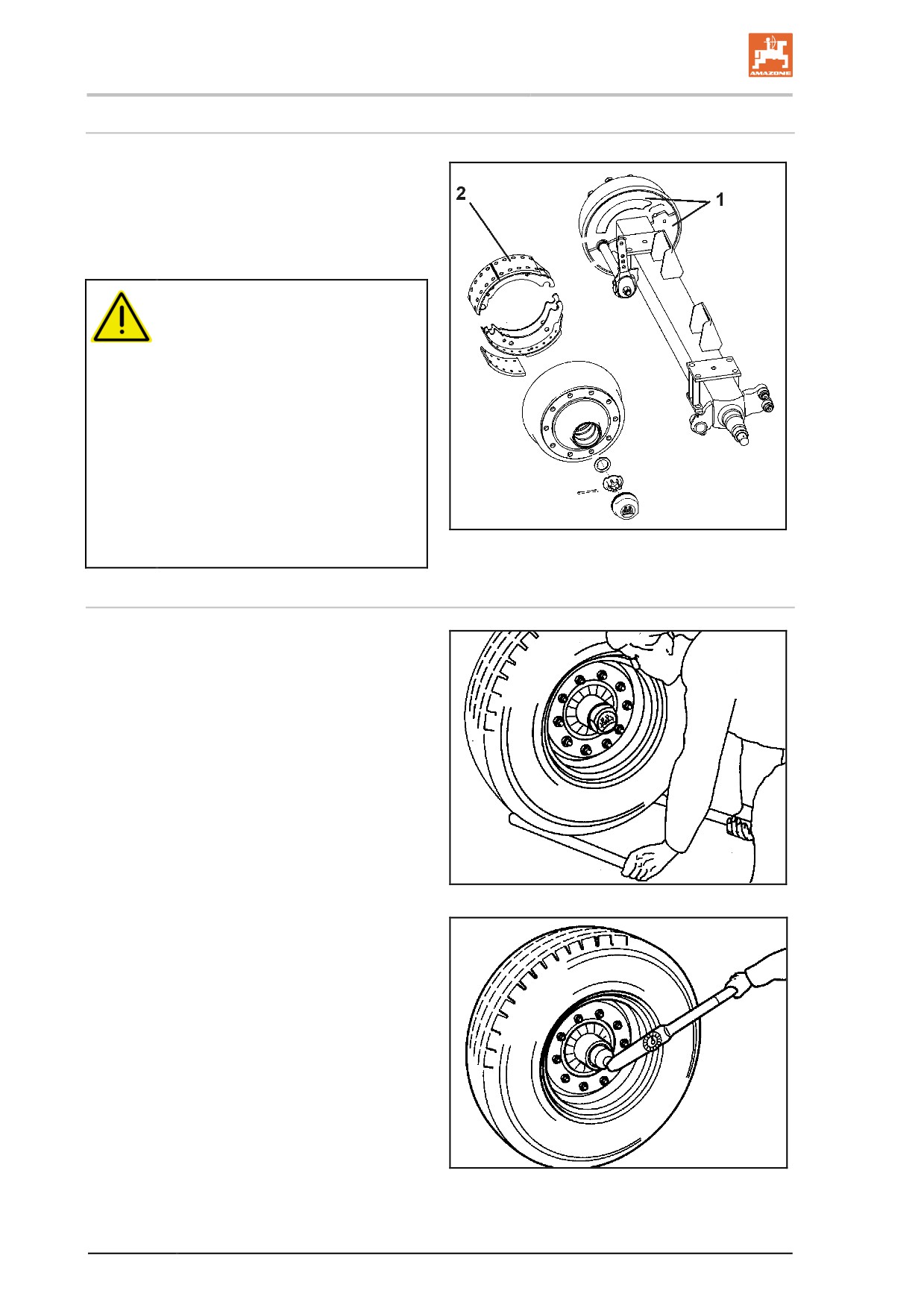
1. Unscrew the two cover plates (Fig. 140/1)
on the inside of the brake drum.
2. Remove any dirt and plant debris which
may have entered the drum.
3. Refit the cover plates.
CAUTION
Dirt entering the drums may be
deposited on the brake pads (Fig.
140/2) and thus die appreciably
reduce brake performance.
Risk of accident.
If dirt is discovered in the brake drum,
the brake pads must be inspected by
a specialist workshop.
For this to happen, the wheel and
brake drum must be removed.
Fig. 136
Checking the play on wheel hub bearings
To check the play on wheel hub bearings, raise
the axle until the wheels turn freely. Release the
brake. Place a lever between the tyre and the
ground and check the play.
If bearing play can be detected:
Adjust the bearing play
•
Remove the dust cup or hub cap.
•
Remove the split pin from the axle nut.
•
Tighten the wheel nut while turning the
wheel at the same time until the wheel hub
is lightly braked as it turns.
•
Turn axle nut back to the next available split
Fig. 137
pin hole. To the next matching hole (max.
30°).
•
Fit split pin and bend slightly open.
•
Top up the dust cap with high melting point
grease and drive it into, or screw it onto the
wheel hub.
Fig. 138
198
Cleaning, maintenance and repair
Brake pad check
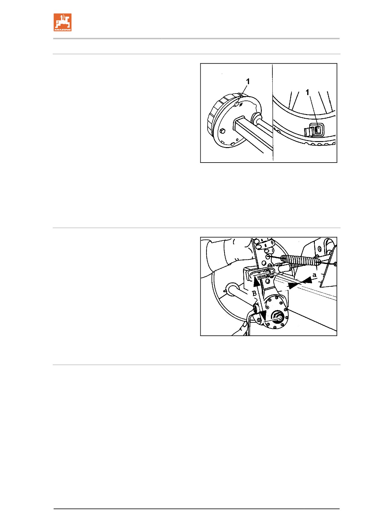
Open the inspection hole (Fig. 143/1) by pulling
out the rubber stopper (if present).
At a residual thickness
a:
for riveted pads
5 mm
(N 2504)
3 mm
b:
for adhesive pads
2 mm
the brake pad must be replaced.
Reinsert the rubber tab.
Brake adjustment
Depending on use, the wear and function of the
brakes must be constantly checked and, if nec-
Fig. 139
essary, readjustment must be carried out. Read-
justment is required after using approx. 2/3 of the
max. cylinder stroke for emergency braking. To
do this, jack up the axle and secure it against
unintended movement.
Adjusting the linkage adjuster
Move the linkage adjuster by hand in the pres-
sure direction. If the free travel of the long-stroke
diaphragm cylinder pressure rod is max. 35 mm,
the wheel brake must be readjusted.
Adjustments are made using the readjustment
hexagon bolt on the linkage adjuster. Set the free
travel "a" to 10-12 % of the connected brake
lever length "B",
e.g. lever length 150 mm = free travel 15 - 18
mm.
Fig. 140
Adjusting the automatic linkage adjuster
Basic settings are made in the same way as for the standard linkage
adjuster. Readjustment occurs automatically at a cam rotation of ap-
prox. 15°.
The ideal lever position (which cannot be altered owing to the attach-
ment of the cylinder) is approx. 15° before perpendicularity, and the
same in the actuation direction.
199
Cleaning, maintenance and repair
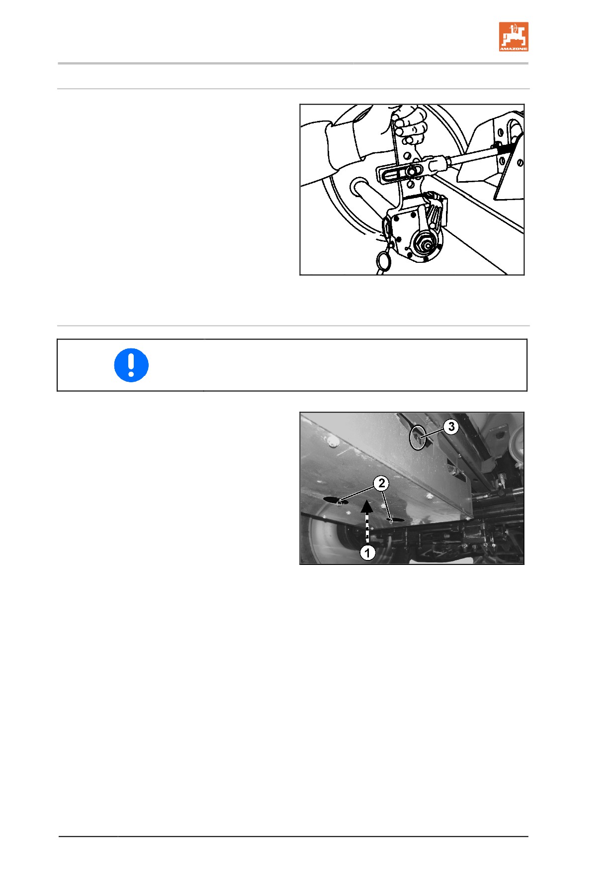
Checking the function of the automatic linkage adjuster
1. Remove the rubber stopper cap.
2. Slacken the adjusting screw (arrow) with a
ring spanner approx. ¾ of a turn anti-
clockwise. There must be a free travel of at
least 50 mm for a lever length of 150 mm.
3. Actuate the brake lever several times by
hand. This should cause a smooth automat-
ic readjustment; it should be possible to
hear the coupling engaging and, on the
back stroke, the adjusting screw should turn
clockwise slightly.
4. Refit the stopper cap.
5. Lubricate with BPW ECO_Li91 special high
Fig. 141
melting point grease.
Air reservoir
Drain the air reservoir every day.
(1) Air reservoir
(2) Drainage valve
(3) Test connection for pressure gauge
1. Pull the drain valve in a sideways direction
using the ring until no more water escapes
from the air reservoir.
→ Water flows out of the drain valve.
2. Unscrew the drain valve from the air reser-
voir and clean the reservoir if there are
signs of dirt.
Fig. 142
200
Cleaning, maintenance and repair
Inspection instructions for the dual circuit service brake system
1.
Leak tightness check
1. Check all connections, pipe lines, hose lines and screw connec-
tions for leak tightness.
2. Remedy leakages.
3. Repair any areas of chafing on pipes and hoses.
4. Replace porous and defective hoses.
5. The dual-circuit service brake system may be considered
leakproof if the drop in pressure is no more than 0.15 bar after
10 minutes.
6. Seal any leaking areas or replace leaking valves.
2.
Checking the pressure in the air reservoir
1. Connect a pressure gauge to the test connection on the air res-
ervoir.
Set value
6.0 to 8.1 + 0.2 bar
3.
Checking the brake cylinder pressure
1. Connect a pressure gauge to the test connection on the brake
cylinder.
Set value:
with brake not applied
0.0 bar
4.
Visual inspection of the brake cylinder
1. Check the dust sleeves or gaiters (Fig. 146/5) for damage.
2. Replace damaged parts.
5.
Joints on brake valves, brake cylinders and brake linkages
Joints on brake valves, brake cylinders and brake linkages must move
freely. Grease or lightly oil, if necessary.
201
Cleaning, maintenance and repair
Adjustment values for the automatic load-dependant braking force regulator (ALB)
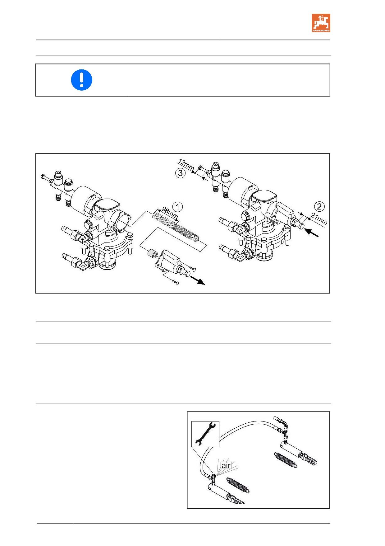
When replacing the breaking force regulator, the adjustment values 1,
2, 3 must be set.
(1) Effective length of the compression spring
(2) The free thread length between nut and cap
(3) The free thread length between nut and bolt
13.5.1 Hydraulic brakes
Check of the hydraulic brake
•
Check all brake hoses for wear
•
check all screw unions for seal tightness
•
renew any worn or damaged parts.
Venting the brake system (workshop work)
After each brake repair, for which the system has
been opened, bleed the brake system, because
air may have entered the pressure hoses.
1. Slightly loosen the vent valve.
2. Actuate the tractor brake.
3. Close the vent valve as soon as oil es-
capes.
→ Collect the escaping oil.
4. Perform a brake check.
202
Cleaning, maintenance and repair
13.6
Parking brake
On new machines, the brake cables of the parking brake may stretch.
Readjust the parking brake,
•
if three quarters of the spindle tensioning distance is required to
firmly apply the parking brake.
•
if you have just fitted new brake pads.
Adjusting the parking brake
When the parking brake is off, the brake cable must be slightly slack.
However, the brake cable must not rest or chafe against other parts of
the vehicle.
1. Release the cable clamps.
2. Shorten the brake cable as appropriate and retighten the cable
clamps.
3. Check for the correct braking effect from the parking brake when
applied.
203