Amazone UX 11200 Trailed field sprayer. Operating Manual (2017) - page 3
Construction and function of the sprayer boom
6.3
Reduction joint on the outer boom (optional)
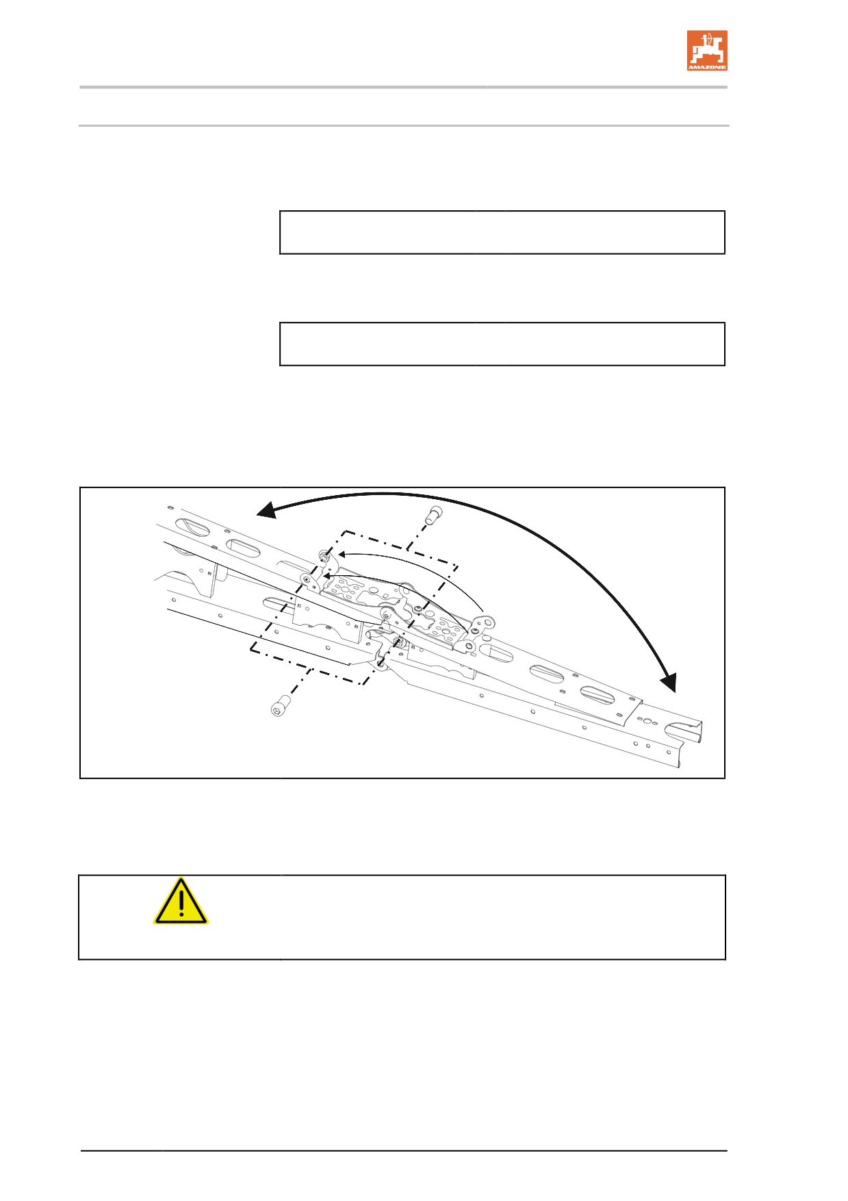
Using the reduction joint, the outer element of the outer boom can be
folded manually to reduce the working width.
Case 1:
Number of nozzles
Number of nozzles on the
=
outer part width section
foldable outer element
→ When spraying with a reduced working width, keep the outer part
width sections switched off.
Case 2:
Number of nozzles
Number of nozzles on the
≠
outer part width section
foldable outer element
→ Close the outer nozzles manually (triple nozzle head).
→ Perform changes on the control terminal.
ο Enter the changed working width.
ο Enter the changed number of nozzles on the outer part
width sections.
Fig. 79
2 bolts lock the folded and unfolded outer element in its respective
end positions.
CAUTION
Before road transport, unfold the outer elements again so that
the transport locking mechanism is active when the boom is
folded.
104
Construction and function of the sprayer boom
6.4
Boom width reduction (option)
With the boom width reduction, one or two booms can remain folded
in during operation depending on the version.
In addition, switch on the hydraulic accumulator (optional) as a colli-
sion protection.
The respective boom part width sections have to be activated in the
on-board computer.
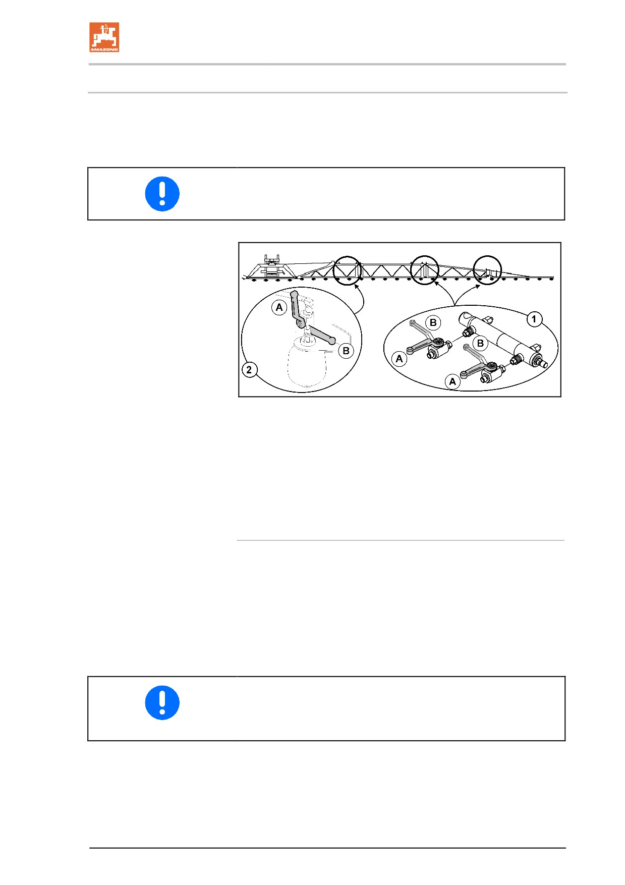
Fig. 80
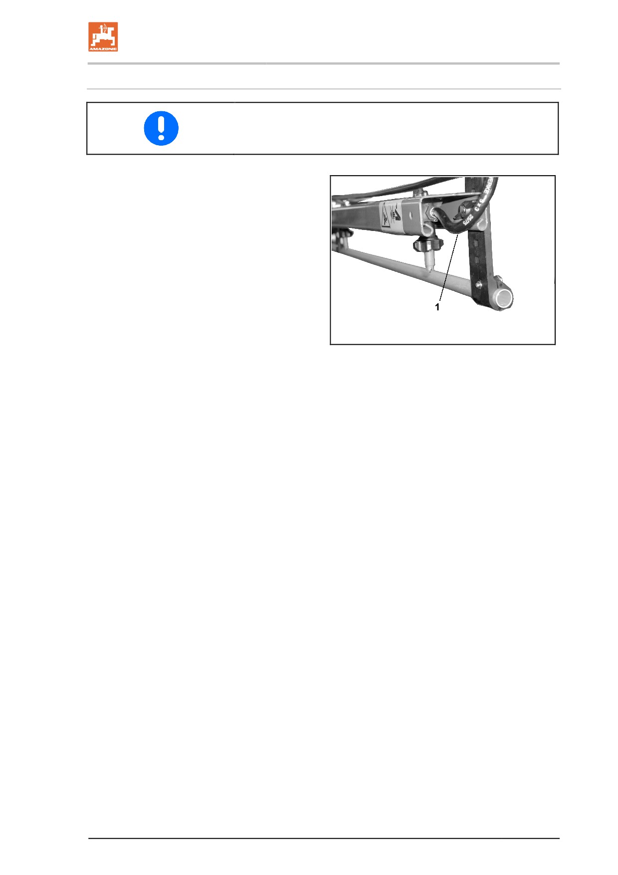
(1) Boom width reduction
(2) Boom width damping
(A) Stop tap opened
(B) Stop tap closed
Working with reduced working width
1. Reduce the boom width hydraulically.
2. Close the stop taps for the boom width reduction.
3. Open the stop tap for the boom damping.
4. Deactivate the respective boom part width sections in the on-
board computer.
5. Perform work with reduced working width.
Close the stop tap for the boom damping.
•
For road transport
•
For use with full working width
105
Construction and function of the sprayer boom
Implements with DistanceControl plus:
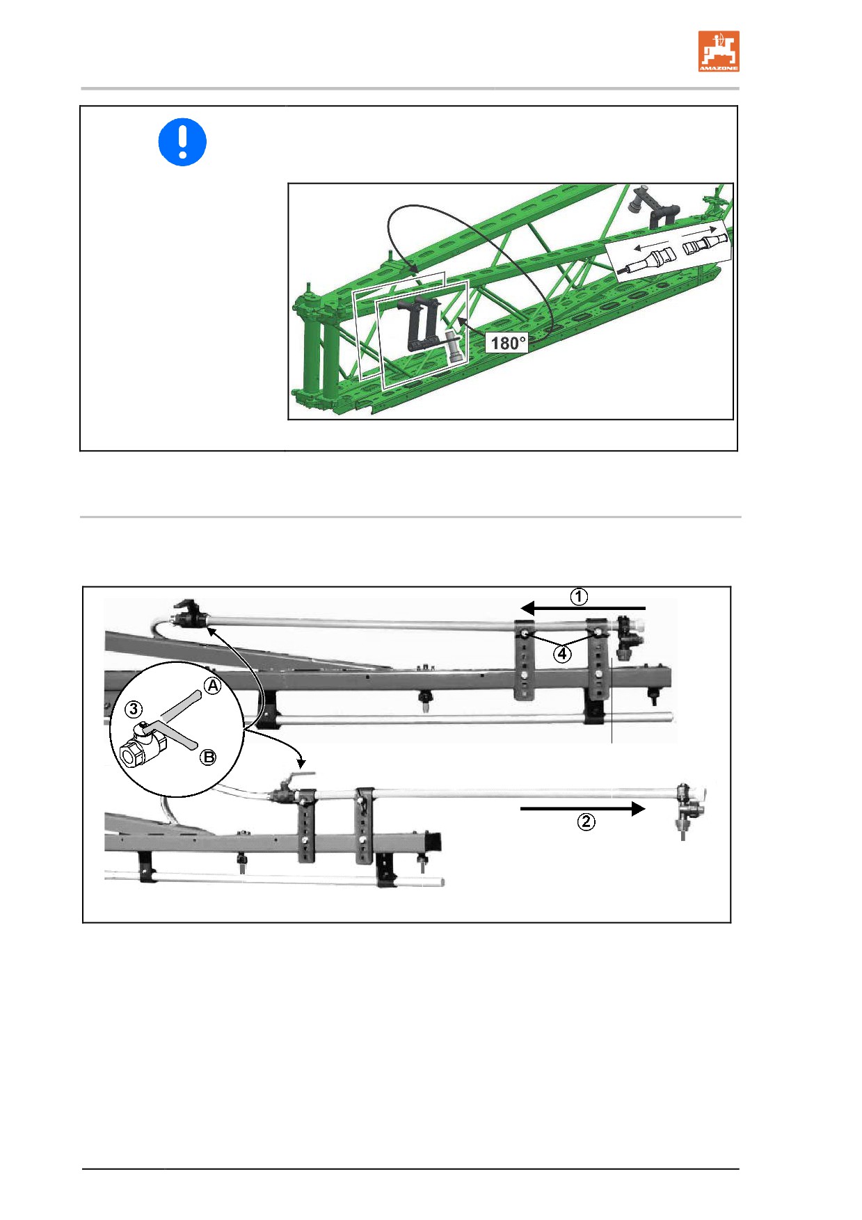
With reduced working width, install each outer sensor rotated by 180°
and disconnect the inner sensor.
Fig. 81
6.5
Boom extension (option)
The boom extension increases the working width infinitely up to 1.20
metres.
Fig. 82
(1) Boom extension in transport position
(2) Boom extension in working position
(3) Stop tap for the outer nozzle
(A)
Stop tap opened
(B)
Stop tap closed
(4) Wing bolts for securing the boom extension in the transport or
working position
106
Construction and function of the sprayer boom
6.6
Hydraulic tilt adjustment (optional)
In unfavourable ground conditions, e.g. when there are ruts of varia-
ble depth or when driving with one side of the vehicle in a furrow, the
sprayer boom can be aligned parallel to the ground or to the target
surface using hydraulic tilt adjustment.
Adjust using operating terminal:
See the operating manual for the operating terminal.
6.7
Distance control (optional)
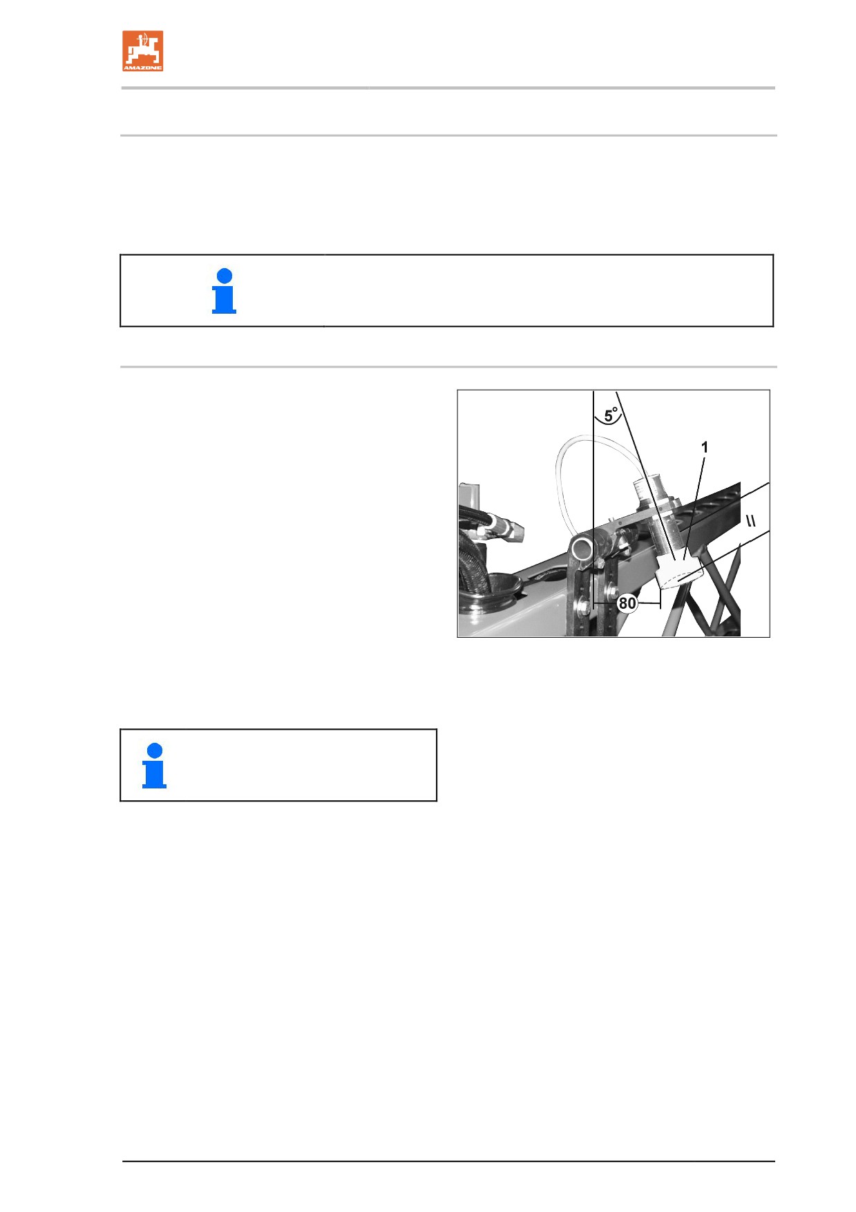
The Distance Control regulating unit for the
sprayer boom automatically holds the sprayer
boom parallel at the desired distance from the
target surface.
•
DistanceControl with 2 sensors
•
DistanceControl with 4 sensors
Ultrasound sensors (Fig. 85/1) detect the dis-
tance to the ground or the crop. If the height
deviates from the desired measurement on one
side, the distance control regulates the tilt ad-
justment in order to adjust the height. If the ter-
rain rises on both sides, the height adjustment
raises the entire boom.
Switching off the sprayer boom on a headland
Fig. 83
will automatically raise the sprayer boom by ap-
prox. 50 cm. When switched back on again, the
sprayer boom is lowered back to the calibrated
height.
See operating manual for software
ISOBUS
•
Setting the ultrasound sensors:
→ see Fig. 85
107
Construction and function of the sprayer boom
6.8
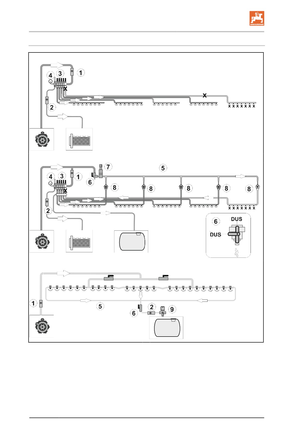
Spray lines
Spray lines with part-width section valves
Spray lines with part-width section valves and DUS pressure circulation system
Spray lines with single nozzle control and DUS Pro pressure circulation system
(1) Flow meter
(6) DUS stop tap
(2) Flow meter
(7) Pressure control valve
(3) Boom part width section valves
(8) Check valve
(4) Bypass valve for low application rates
(9) Pressure control valve
(5) Pressure circulation line
108
Construction and function of the sprayer boom
Pressure circulating system (DUS)
Part-width section control: Pressure circulating system must generally
be switched off when using drag hoses.
The pressure circulating system
•
enables the constant circulation of liquid in
the spray line. For these purposes, a suc-
tion port hose (Fig. 98/1) is assigned to
each part width section.
•
enables operation using spray liquid or
flushing water, as desired.
•
reduces the undiluted residue for all spray
lines to 2 l.
The constant circulation of liquid
•
enables production of an even spray pattern
right from the start, because spray liquid is
available at every spraying nozzle immedi-
Fig. 84
ately after the sprayer boom is switched on,
with no delay.
•
prevents damage to the spray line.
109
Construction and function of the sprayer boom
6.8.1
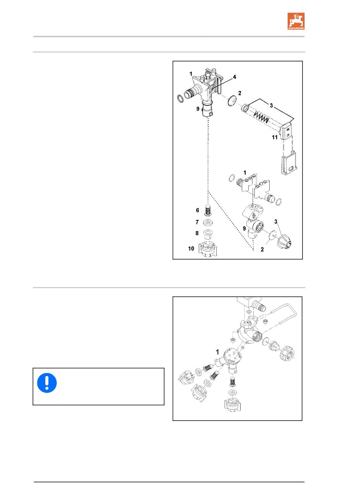
Single nozzles
Fig. 87/...
(1) Nozzle body with bayonet connection
(standard).
(2) Diaphragm. If the pressure in the spray line
falls below approx. 0.5 bar, the spring ele-
ment (3) presses the diaphragm onto the
diaphragm seat (4) in the nozzle body. This
ensures that when the sprayer boom is
switched off, the nozzles are deactivated
without subsequent dripping.
(3) Spring element.
(4) Diaphragm seat.
(5) Slider - holds the entire diaphragm valve in
the nozzle body.
(6) Nozzle filter; fitted as standard on ma-
chines with 50 mesh/inch, is inserted from
below into the nozzle body. Refer to the
"Nozzle filter" section.
(7) Rubber seal.
(8) Nozzle.
(9) Bayonet connection.
(10) Coloured bayonet cap.
(11) Spring element housing.
Fig. 85
6.8.2
Multi nozzles (optional)
When using multiple nozzle types, it is beneficial
to use multi nozzles (Fig. 88). In each case, the
nozzle pointing upwards is the one that is sup-
plied.
Turning the multi nozzles head (Fig. 88/1) anti-
clockwise brings a different nozzle into play.
The multi nozzles head is switched off in the
intermediate positions. This provides the possi-
bility of reducing the working width of the boom.
Rinse the spray lines before twisting
the multi nozzles head onto another
nozzle type.
Fig. 86
110
Construction and function of the sprayer boom
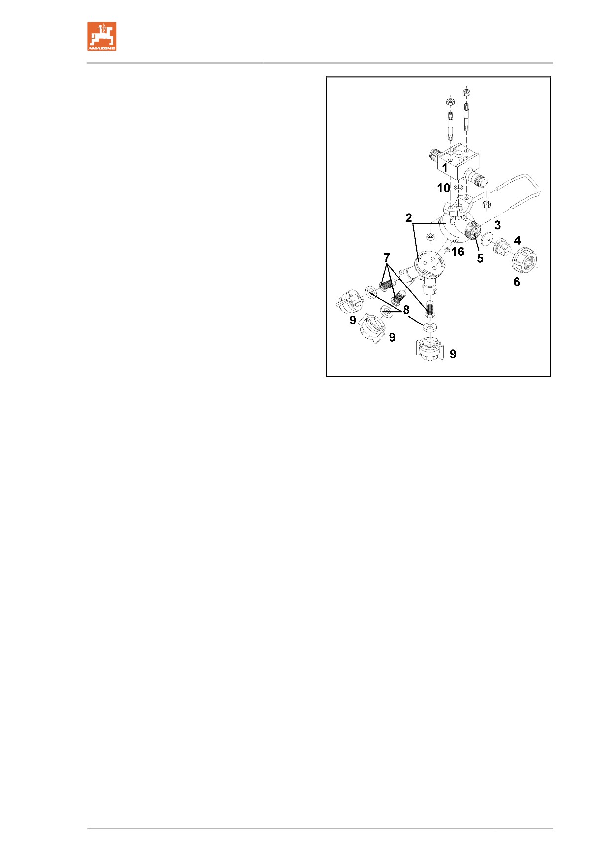
(1) Nozzle carrier.
(2) Triple nozzle head.
(3) Diaphragm. If the pressure in the nozzle
line falls below approx. 0.5 bar, the spring
element (4) presses the diaphragm onto the
diaphragm seat (5) in the three-way nozzle
carrier. This ensures that when the sprayer
boom is switched off, the nozzles are deac-
tivated without subsequent dripping.
(4) Spring element.
(5) Diaphragm seat.
(6) Sleeve nut - holds the entire diaphragm
valve in the three-way nozzle carrier.
(7) Nozzle filter; fitted as standard on machines
with 50 mesh/inch.
(8) Rubber seal.
(9) Bayonet cap.
(10) O-ring.
Fig. 87
111
Construction and function of the sprayer boom
6.8.3
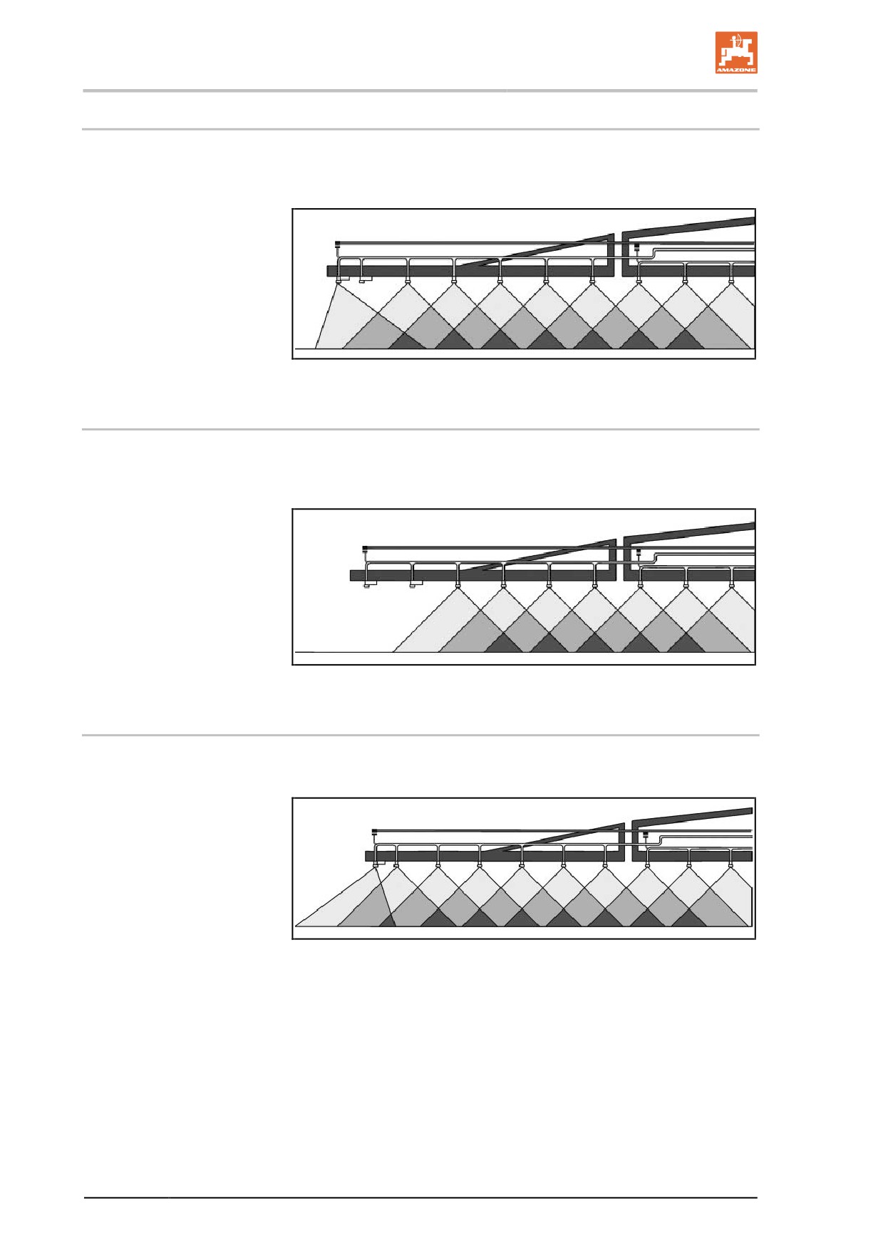
Electric boundary nozzles (optional)
Using boundary nozzle switching, the last nozzle can be switched off
from the tractor and a boundary nozzle can be electrically switched on
25 cm further out (right at the edge of the field).
Fig. 88
6.8.4
Electric end nozzle switching (optional)
Using end nozzle switching, up to three of the outer nozzles at the
edge of the field close to a water source can be electrically switched
off from the tractor).
Fig. 89
6.8.5
Electric additional nozzle switching (optional)
With the additional nozzle switching, another exterior nozzle is cut in,
increasing the working width by one metre.
Fig. 90
112
Construction and function of the sprayer boom
6.9
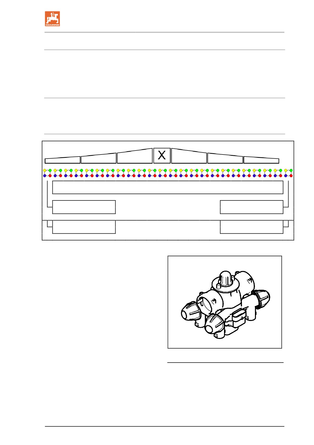
Automatic single nozzle control (optional)
50 cm part width sections can be controlled separately by the electric
single nozzle control. In combination with the automatic part width
section control "Section Control", overlapping can be reduced to a
minimum area.
6.9.1
Single nozzle control AmaSwitch
Each nozzle can be switched on and off separately via Section Con-
trol.
6.9.2
4-way AmaSelect single nozzle control
Standard nozzle body
Extra nozzle body
Extra nozzle body
Extra nozzle body
Extra nozzle body
•
The sprayer boom is fitted with 4-way noz-
zle bodies. Each of them is operated by an
electric motor.
•
The nozzles can be switched on or off as
desired (depending on Section Control).
•
Due to the 4-way nozzle bodies, several
nozzles can be simultaneously active in a
nozzle body.
•
Alternatively, the nozzles can be manually
selected.
•
For boundary treatment, an extra nozzle
body can be separately configured.
•
LED single nozzle illumination integrated in
the nozzle body.
113
Construction and function of the sprayer boom
•
Nozzle spacing of 25 cm possible.
During assembly, ensure that the two out-
lets facing the front on the implement are
used for the assembly.
Manual nozzle selection:
The control terminal can be used to select the
nozzle or the nozzle combination.
Automatic nozzle selection:
The nozzle or nozzle combination is automatical-
ly selected during spraying in accordance with
the entered border conditions.
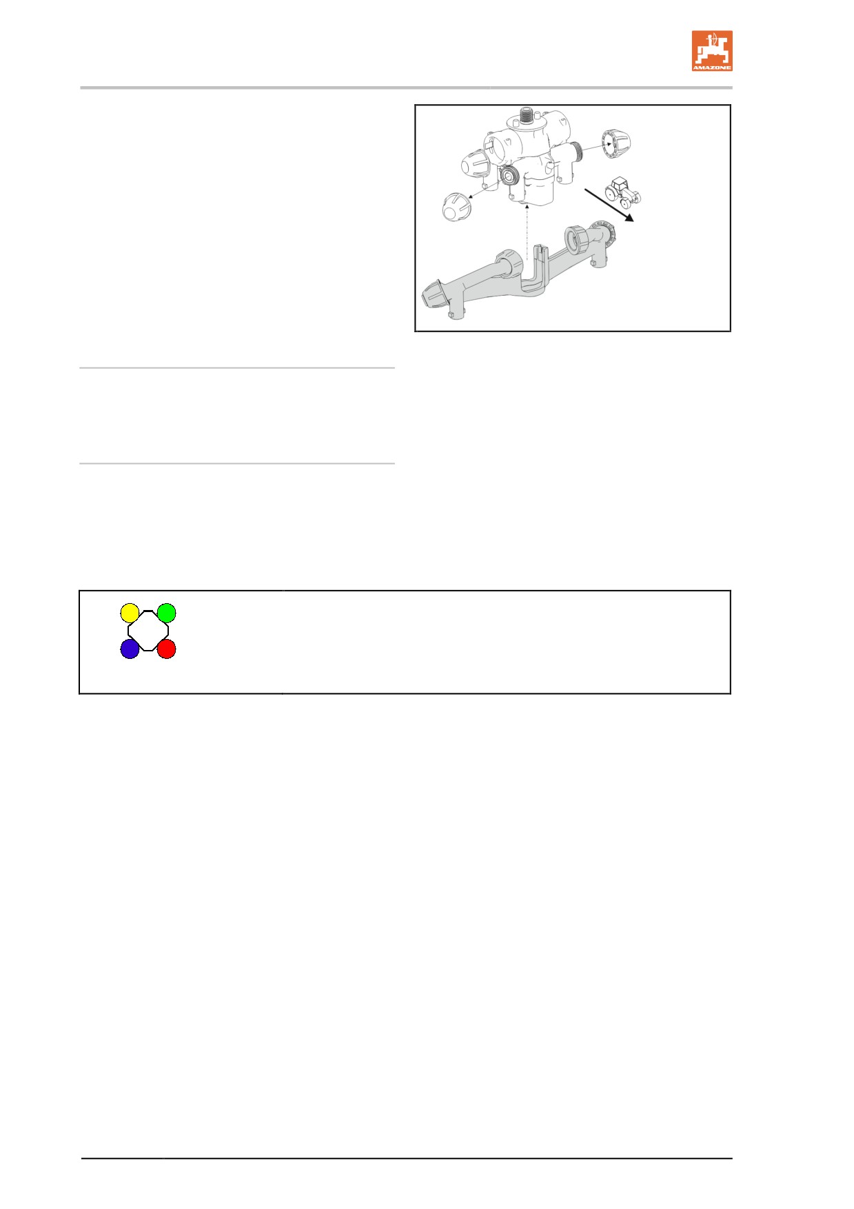
Symbol for nozzle housings - AmaSelect.
The arrow shows the direction of travel.
→ This is important for the assembly of the nozzles in the nozzle
bodies!
114
Construction and function of the sprayer boom
6.10
Special optional equipment for liquid fertiliser
There are currently two main types of liquid fertiliser available:
•
Ammonium nitrate / urea solution (AUS) with 28 kg N per 100 kg
AUS.
•
An NP solution 10-34-0 with 10 kg N and 34 kg P2O5 per 100 kg
NP solution.
If the liquid fertiliser is sprayed using flat-fan nozzles, multiply the
corresponding values from the spray table for the spray rate (l/ha) by
0.88 for AUS and by 0.85 for NP solutions, as the spray rates listed
(in l/ha) only apply for water.
As a rule:
Use coarse-dropped application for liquid fertiliser to avoid chemical
burns to the plants. Overly large drops roll off the leaf and drops
which are too small cause a magnifying glass effect, which burns the
leaves. Too much fertiliser may cause burns to appear on the leaves
due to the salt concentration in the fertiliser.
As a rule, do not spray more liquid fertiliser than, for example, 40 kg N
(see also "Conversion table for spraying liquid fertiliser"). Always dis-
continue nozzle-based AUS fertilisation at development stage EC-39,
because chemical burns on ears have a particularly bad effect.
6.10.1
Three-ray nozzles (optional)
The use of three-ray nozzles for applying liquid fertiliser is beneficial if
the liquid fertiliser needs to be taken up more by the roots of the plant
than through the leaves.
Thanks to its three openings, the dosing aperture, which is integrated
into the nozzle, ensures a coarse-dropped, almost depressurised dis-
tribution of the liquid fertiliser. This prevents an undesirable spray mist
and the formation of smaller drops. The coarse drops produced by the
three-ray nozzle hit the plants with little force and roll off their surface.
Although this avoids damage from burns to the greatest extent
possible, avoid the use of three-ray nozzles for late top dressing
and use drag hoses.
For all three-ray nozzles listed in the following, only use the black
bayonet nut.
Different three-ray nozzles and their operational areas
(at 8 km/h)
•
yellow
50 - 80l AUS / ha
•
red
80 - 126l AUS / ha
•
blue
115 - 180l AUS / ha
•
white
155 - 267l AUS / ha
115
Construction and function of the sprayer boom
6.10.2 Line filter for spray lines
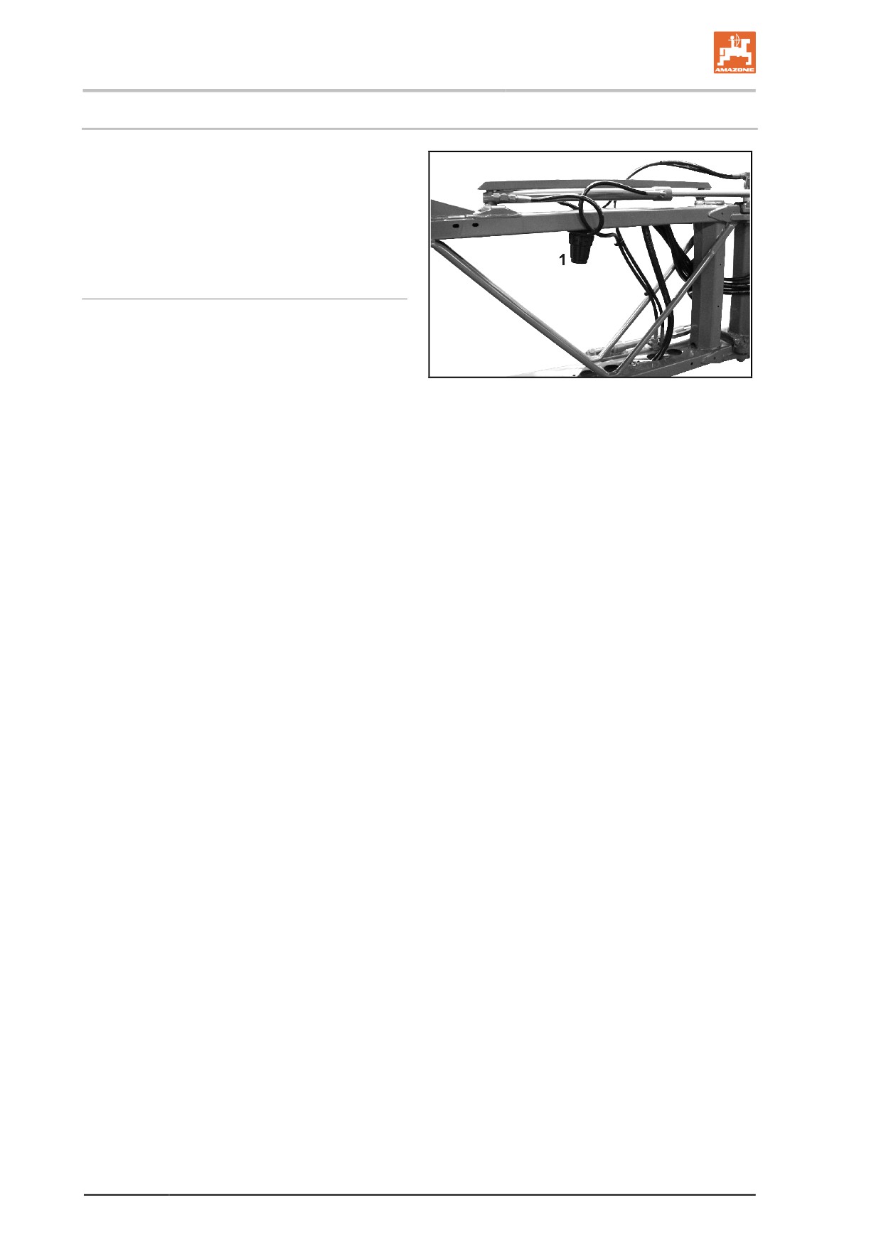
Line filters (Fig. 93/1) are
•
fitted in the spray lines in each part width
section.
•
an additional measure to avoid contamina-
tion of the spraying nozzles.
Overview of the filter inserts
•
Filter insert with 50 mesh/inch (blue)
•
Filter insert with 80 mesh/inch (grey)
•
Filter insert with 100 mesh/inch (red)
Fig. 91
116
Construction and function of the sprayer boom
6.10.3
7 hole nozzles / FD nozzles (optional)
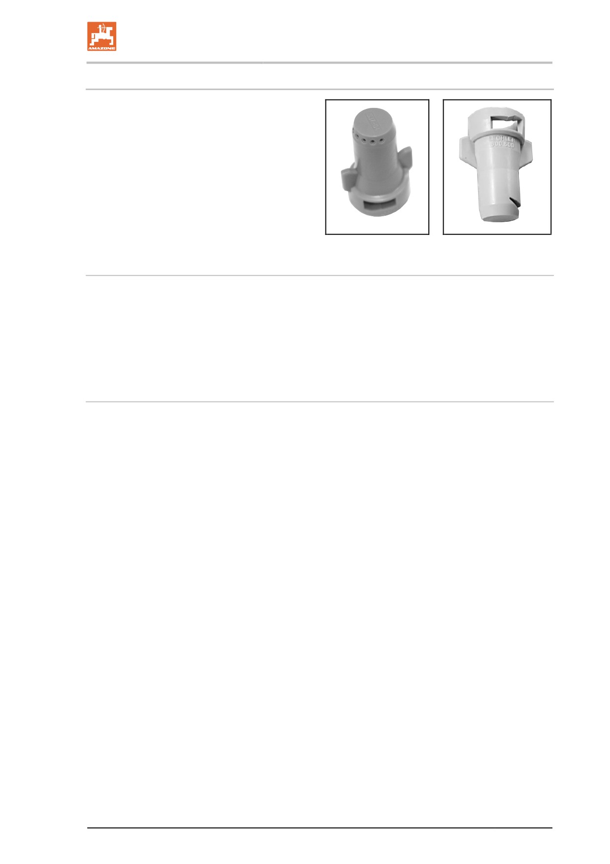
The same conditions apply for using 7 hole noz-
zles / FD nozzles as for the three-ray nozzles. In
contrast to the three-ray nozzle, in the case of
the 7 hole nozzle / FD nozzles, the outlets are
not oriented downwards, but instead point to the
side. This allows very large drops to be produced
on the plants using only slight impact forces.
Fig. 94:
→
7 hole nozzle
Fig. 95:
→ FD nozzle
Fig. 92
Fig. 93
The following 7-hole nozzles are available
•
SJ7-02-CE
74 - 120l AUS
(at 8 km/h)
•
SJ7-03-CE
110 - 180l AUS
•
SJ7-04-CE
148 - 240l AUS
•
SJ7-05-CE
184 - 300l AUS
•
SJ7-06-CE
222 - 411l AUS
•
SJ7-08-CE
295 - 480l AUS
The following FD nozzles are available
•
FD 04
150 - 240 l AHL/ha
(at 8 km/h)
•
FD 05
190 - 300 l AHL/ha
•
FD 06
230 - 360 l AHL/ha
•
FD 08
300 - 480 l AHL/ha
•
FD 10
370 - 600 l AHL/ha*
117
Construction and function of the sprayer boom
6.11
Foam marker (optional)
The foam marker, which can be retrofitted at any point, makes it
possible to drive the next bout precisely when spraying fields
without marked-out tramlines.
Marking involves the use of foam bubbles. The foam bubbles are
laid at adjustable intervals of approx. 10 - 15 metres, providing a
clearly-visible orientation line. The foam bubbles dissolve after a
certain time without leaving any residue behind.
Set the interval between the individual applications of bubbles
using the slotted screw
as follows:
ο turn clockwise - distance is increased,
ο turn anti-clockwise, - distance is decreased
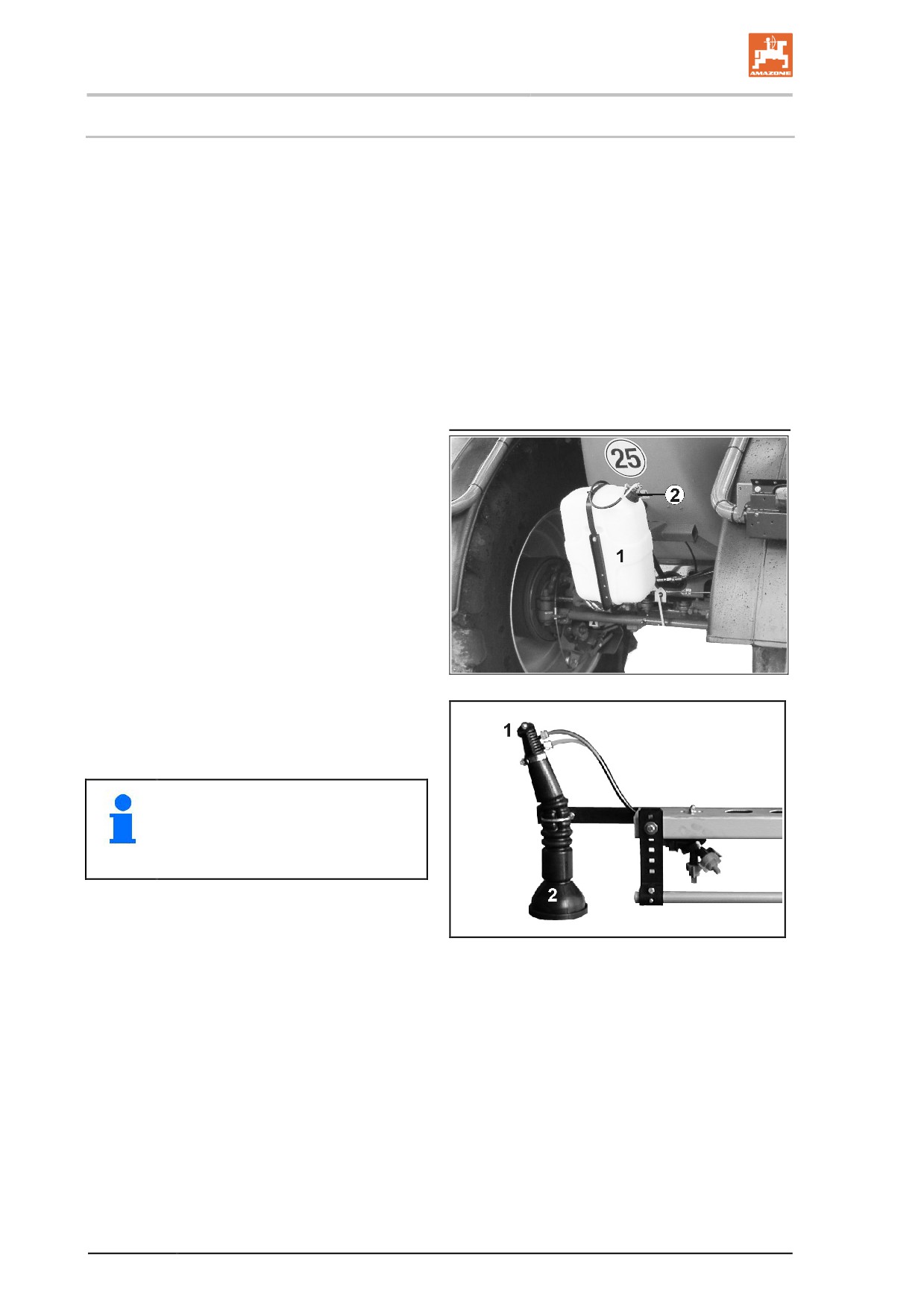
Fig. 96/...
(1) Tank
(2) Slotted screw
(3) Compressor
Fig. 94
Fig. 97/...
(1) Air and liquid agitator
(2) Flexible plastic nozzle
See operating manual for software
ISOBUS.
Fig. 95
118
Construction and function of the sprayer boom
6.12
Lift module
(optional)
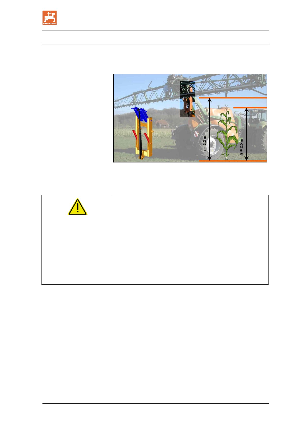
The lift module allows the sprayer boom to be raised by an additional
70 cm to a nozzle height of 3.20 m.
Fig. 96
The lift module is actuated using the tractor control unit yellow.
DANGER
Risk of accidents and danger of damaging the machine.
•
When driving on the roads, the sprayer boom must not be raised
above the lifting module.
→ The total height of the machine with lifting module can be con-
siderably higher than 4 m.
•
Use the lifting module only when the sprayer boom is folded out.
•
Lower the lifting module again before folding in the sprayer
boom. The sprayer boom can otherwise not be put into the
transport lock.
•
Always lift or lower the lifting module to the end position!
119
Commissioning
7
Commissioning
This section contains information
•
on commissioning your machine.
•
on checking if it is possible to connect the machine to your trac-
tor.
•
Before operating the machine for the first time the operator must
have read and understood the operating manual.
•
Comply with the section "Safety information for the user", starting
on page 28 when
ο coupling and uncoupling the machine
ο transporting the machine
ο using the machine
•
Only couple and transport the machine to a tractor which is suit-
able for the task.
•
The tractor and machine must meet the national road traffic
regulations.
•
The operator and the user shall be responsible for compliance
with the statutory road traffic regulations.
WARNING
Risk of crushing, shearing, cutting, and being drawn in or
trapped in the vicinity of hydraulically or electrically actuated
components.
Do not block the operator controls on the tractor which are used for
hydraulic and electrical movements of components, e.g. folding,
swivelling and pushing movements. The movement must stop auto-
matically when you release the appropriate control. This does not
apply to equipment movements that:
•
are continuous or
•
are automatically locked or
•
require a floating position or pressed position to function
120
Commissioning
7.1
Checking the suitability of the tractor
WARNING
Risk of breaking during operation, insufficient stability and in-
sufficient tractor steering and braking power from improper use
of the tractor.
•
Check the suitability of your tractor, before connecting the ma-
chine to the tractor.
You may only connect the machine to tractors suitable for the
purpose.
•
Carry out a brake test to check whether the tractor achieves the
required braking rate with the machine connected.
Requirements for the suitability of a tractor are, in particular:
•
Permissible total weight
•
Permissible approved axle loads
•
Permissible drawbar load at the tractor coupling point
•
Load capacity of the tyres fitted
•
The approved trailer load must be sufficient
You can find this data on the rating plate or in the vehicle docu-
mentation and in the tractor operating manual.
The front axle of the tractor must always be subjected to at least 20%
of the dead-weight of the tractor.
The tractor must achieve the brake rate specified by the tractor manu-
facturer, even with the machine connected.
7.1.1
Calculating the actual values for the total tractor weight, tractor axle loads
and tyre load capacities, as well as the minimum ballast
The permissible total tractor weight, specified in the vehicle documen-
tation, must be greater than the sum of the
•
Tractor empty weight,
•
Ballast weight and
•
Total weight of the connected machine or drawbar load of the
connected machine
This information is only valid for the Federal Republic of Germa-
ny:
If, having tried all possible alternatives, it is not possible to comply
with the axle loads and / or the permissible total weight, then a survey
by an officially-recognised motor vehicle traffic expert can, with the
approval of the tractor manufacturer, be used as a basis for the au-
thority responsible to issue an exceptional approval according to § 70
of the German Regulations Authorising the Use of Vehicles for Road
Traffic and the required approval according to § 29, paragraph 3 of
the German Road Traffic Regulations.
121
Commissioning
7.1.1.1 Data required for the calculation
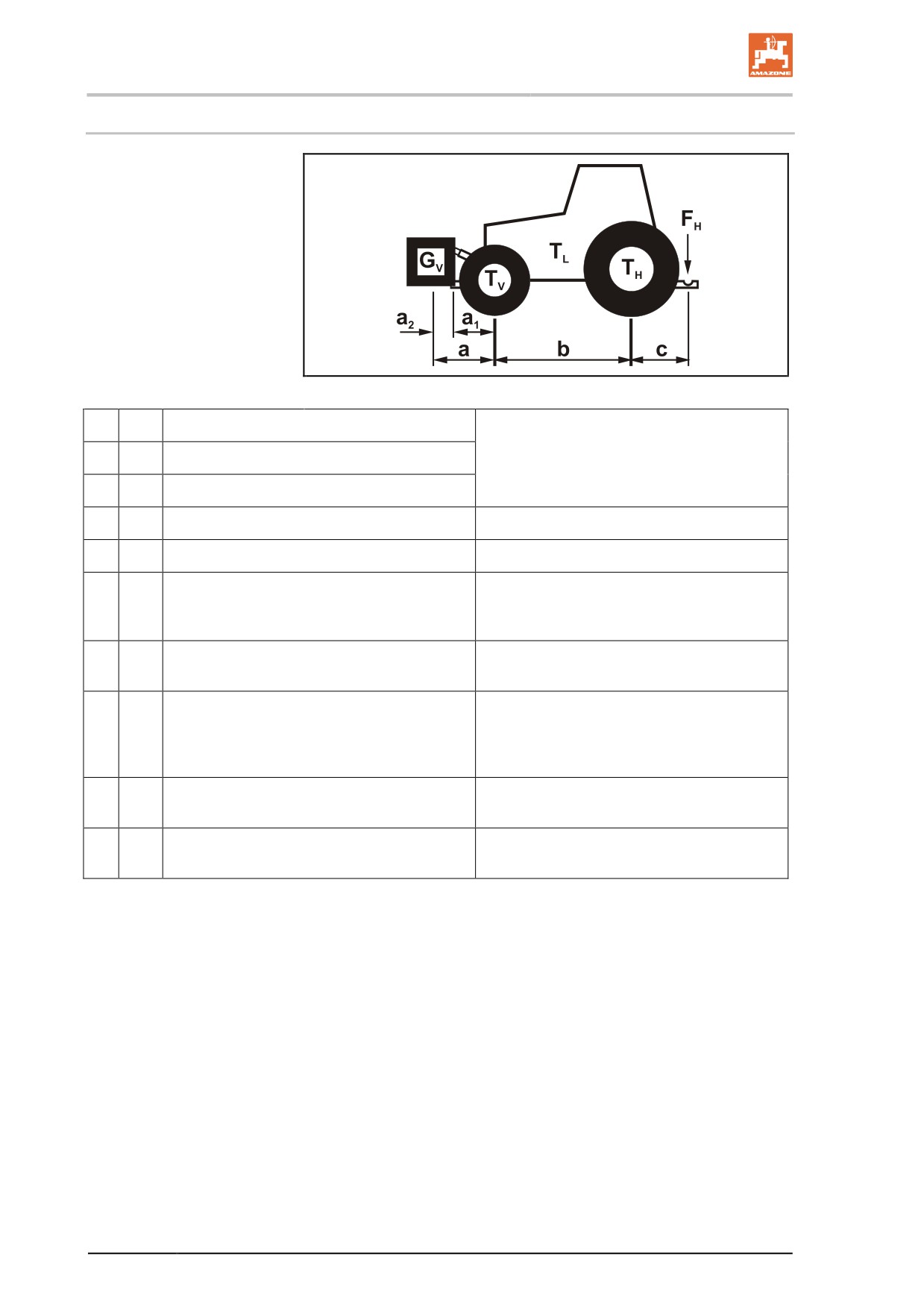
Fig. 97
TL
[kg]
Tractor empty weight
See tractor operating manual or vehicle
TV
[kg]
Front axle load of the empty tractor
documentation
TH
[kg]
Rear axle load of the empty tractor
GV
[kg]
Front weight (if available)
See front weight in technical data, or weigh
FH
[kg]
Maximum drawbar load
See technical data of machine
a
[m]
Distance between the centre of gravity of the
See technical data of tractor and front ma-
front machine mounting or the front ballast
chine mounting or front ballast or measure-
and the centre of the front axle (total a1 + a2)
ment
a1
[m]
Distance from the centre of the front axle to
See tractor operating manual or measure-
the centre of the lower link connection
ment
a2
[m]
Distance between the centre of the lower
See technical data of front machine mount-
link connection point and the centre of gravi-
ing or front ballast or measurement
ty of the front machine mount or front ballast
(centre of gravity distance)
b
[m]
Tractor wheel base
See tractor operating manual or vehicle
documents or measurement
c
[m]
Distance between the centre of the rear axle
See tractor operating manual or vehicle
and the centre of the lower link connection
documents or measurement
122
Commissioning
7.1.1.2
Calculation of the required minimum ballasting at the front GV min of the tractor for
assurance of the steering capability
F •c−T •b+
,
•T
•b
H
V
L
G
=
V
min
a
+b
Enter the numeric value for the calculated minimum ballast G
V min,
required on the front side of the tractor, in the table (Section 7.1.1.7).
7.1.1.3
Calculation of the actual front axle load of the tractor TV tat
G •(a+b)+T •b−
F
•c
V
V
H
T
=
V tat
b
Enter the numeric value for the calculated actual front axle load and
the approved tractor front axle load specified in the tractor operating
manual in the table (Section 7.1.1.7).
7.1.1.4
Calculation of the actual total weight of the combined tractor and machine
G
=G
+
T
+
F
tat
V
L
H
Enter the numeric value for the calculated actual total weight and the
approved total tractor weight specified in the tractor operating manual
in the table (Section 7.1.1.7).
7.1.1.5
Calculation of the actual rear axle load of the tractor TH tat
T
=
G
−
T
H tat
tat
V tat
Enter the numeric value for the calculated actual rear axle load and
the approved tractor rear axle load specified in the tractor operating
manual in the table (Section 7.1.1.7).
7.1.1.6
Tyre load capacity
Enter the double value (two tyres) of the approved load capacity (see,
for example, tyre manufacturer's documentation) in the table (Section
7.1.1.7).
123
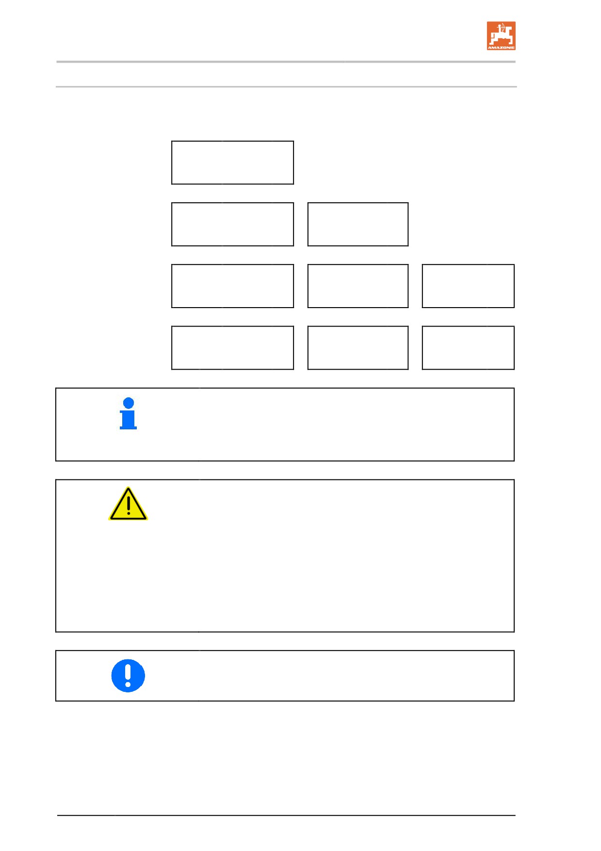
Commissioning
7.1.1.7 Table
Actual value according to
Permissible value
Double the permis-
calculation
according to tractor
sible load capacity
operating manual
(two tyres)
Minimum ballast front /
kg
--
--
rear
/
Total weight
kg
≤
kg
--
Front axle load
kg
≤
kg
≤
kg
Rear axle load
kg
≤
kg
≤
kg
•
You can find the permissible values for the total tractor weight,
axle loads and load capacities in the tractor registration papers.
•
The actually calculated values must be less than or equal to ( ≤ )
the permissible values.
WARNING
Risk of crushing, cutting, being caught or drawn in, or impact
through insufficient stability and insufficient tractor steering and
brake power.
It is forbidden to couple the machine to the tractor used as the basis
for calculation, if
•
one of the actual, calculated values is greater than the permissi-
ble value.
•
there is no front ballast (if required) attached to the tractor for the
minimum front ballast (GV min).
•
You must use a front weight, which is equal to at least the re-
quired minimum front ballast (GV min).
124
Commissioning
7.1.2
Requirements for tractor operation with attached machines
WARNING
Risk of breakage during operation of components through unap-
proved combinations of connecting equipment.
•
Ensure:
ο that the connection fitting on the tractor possesses a per-
missible drawbar load sufficient for the actual drawbar load.
ο that the axle loads and weights of the tractor altered by the
drawbar load are within the approved limits. If necessary,
weigh them.
ο that the tractor's actual static rear axle weight does not ex-
ceed the permissible rear axle weight.
ο that the permissible total weight of the tractor is observed
ο that the approved load capacities of the tractor tyres are not
exceeded.
125
Commissioning
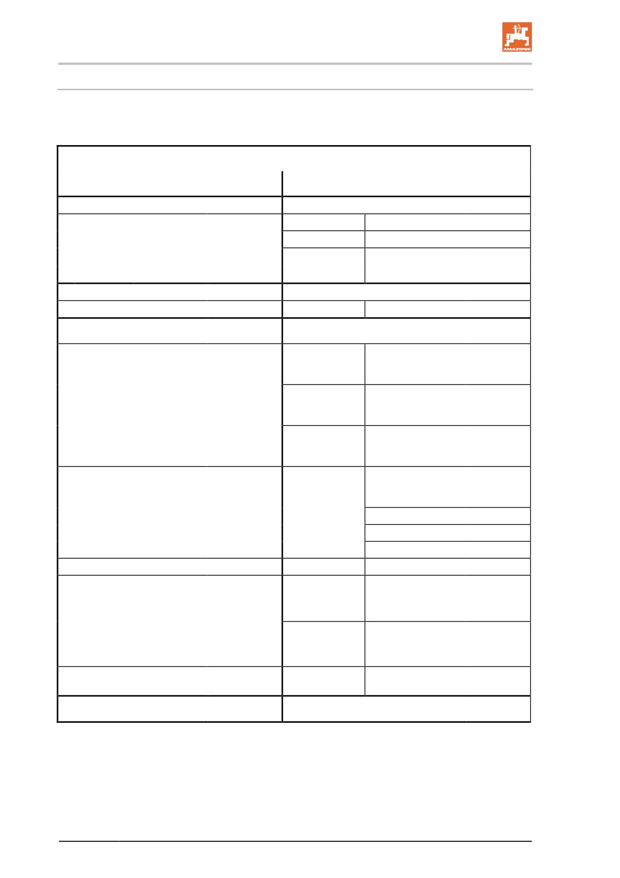
7.1.2.1 Combination options of coupling devices
The table shows the permitted combination options of coupling devic-
es for the tractor and implement.
Coupling device
Tractor
AMAZONE implement
Upper hitch
Pin coupling, form A, B, C
Drawbar eye
Socket Ø 40 mm
(ISO 5692-2)
A not automatically
Drawbar eye
Ø 40 mm
(ISO 8755)
(ISO 6489-2)
B automatic smooth pin
Ø 50 mm, only com-
Drawbar eye
(ISO 1102)
patible with form A
C automatic curved pin
Upper / lower hitch
Ball head coupling Ø 80 mm
(ISO 24347)
Ball coupling
Ø 80 mm
(ISO 24347)
Lower hitch
Centre bore Ø 50
Drawbar eye
mm
(ISO 5692-1)
Eyelet Ø 30 mm
compatible only with
Swivel drawbar
Towing hooks / hitch hooks
(ISO 6489-19)
form Y, hole
(ISO 5692-3)
eye
Ø 50 mm,
Centre bore Ø 50
Drawbar eye
mm
(ISO 20019)
Eyelet Ø 30 - 41 mm
Centre bore Ø 50
mm
(ISO 5692-1)
Eyelet Ø 30 mm
Drawbar - Category 2
(ISO 6489-3)
Drawbar eye
Socket Ø 40 mm
(ISO 5692-2)
Ø 40 mm
(ISO 8755)
Ø 50 mm
(ISO 1102)
Drawbar
(ISO 6489-3)
Drawbar eye
(ISO 21244)
Centre bore Ø 50
mm
Drawbar eye
(ISO 5692-1)
Eyelet Ø 30 mm
Drawbar / Piton-fix
(ISO 6489-4)
compatible only with
Swivel drawbar
form Y, hole
(ISO 5692-3)
eye
Ø 50 mm
Swivel drawbar
Yoke that cannot be rotated
(ISO 6489-5)
(ISO 5692-3)
eye
Lower link hitch
(ISO 730)
Lower link traverse
(ISO 730)
126
Commissioning
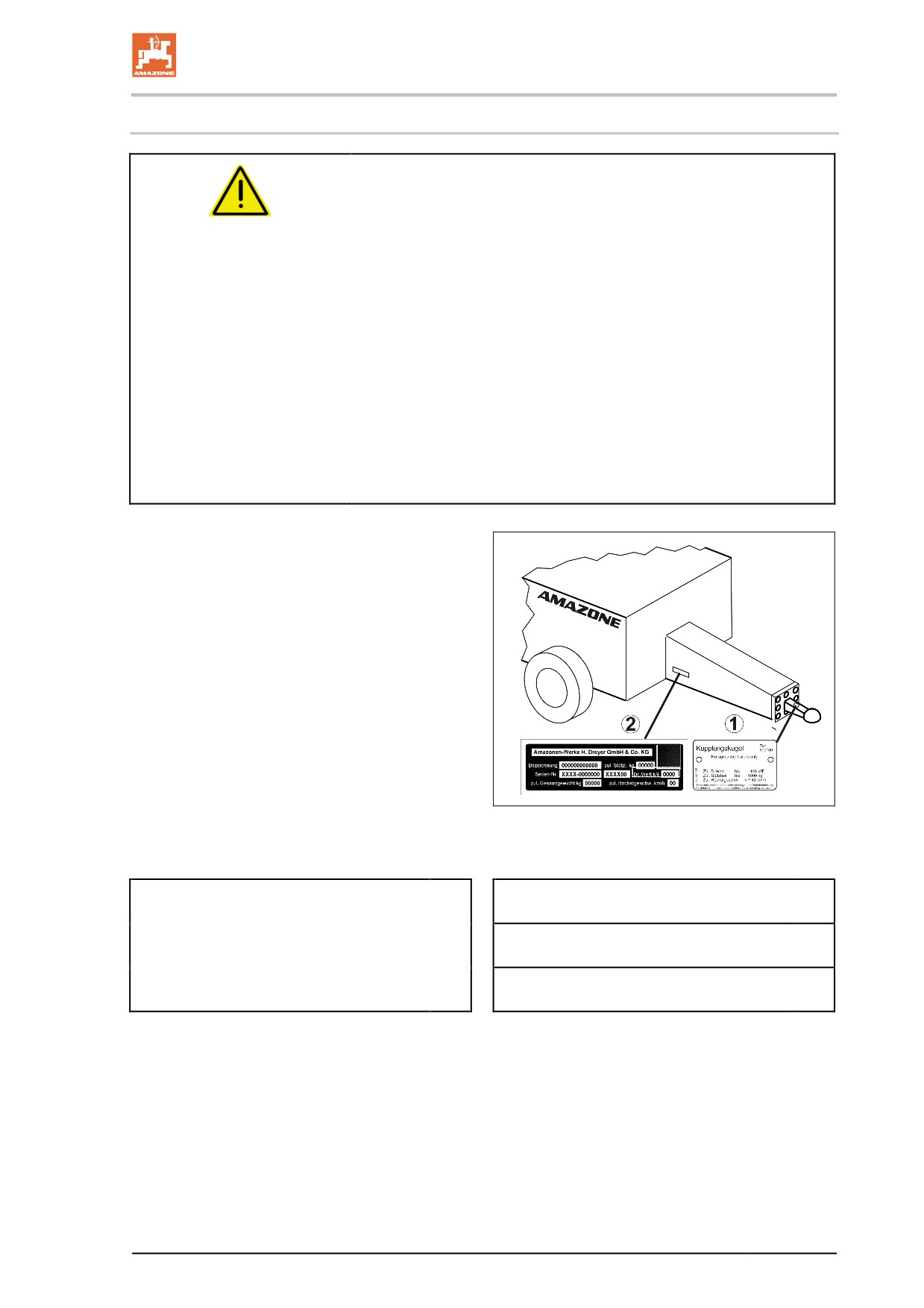
7.1.2.2 Compare the permissible DC value with actual DC value
WARNING
Danger from breaking the coupling devices between the tractor
and the implement when the tractor is not used for its intended
purpose!
1. Calculate the actual DC value of your combination, comprising
tractor and implement.
2. Compare the actual DC value with the following permissible DC
values:
•
Coupling device of the implement
•
Drawbar of the implement
•
Coupling device of the tractor
The actual DC value calculated for the combination must be less than
or equal ( ≤ ) to the DC values specified.
The permissible DC values of the implement can
be found on the rating plate of the coupling de-
vice (1) and the drawbar (2).
The permissible DC value of the tractor coupling
device can be found directly on the coupling
device / in the operating manual of your tractor.
actually calculated
specified DC value
DC value for the combination
Coupling device on the tractor
≤
kN
Coupling device of the implement
kN
≤
kN
Drawbar of the implement
≤
kN
127
Commissioning
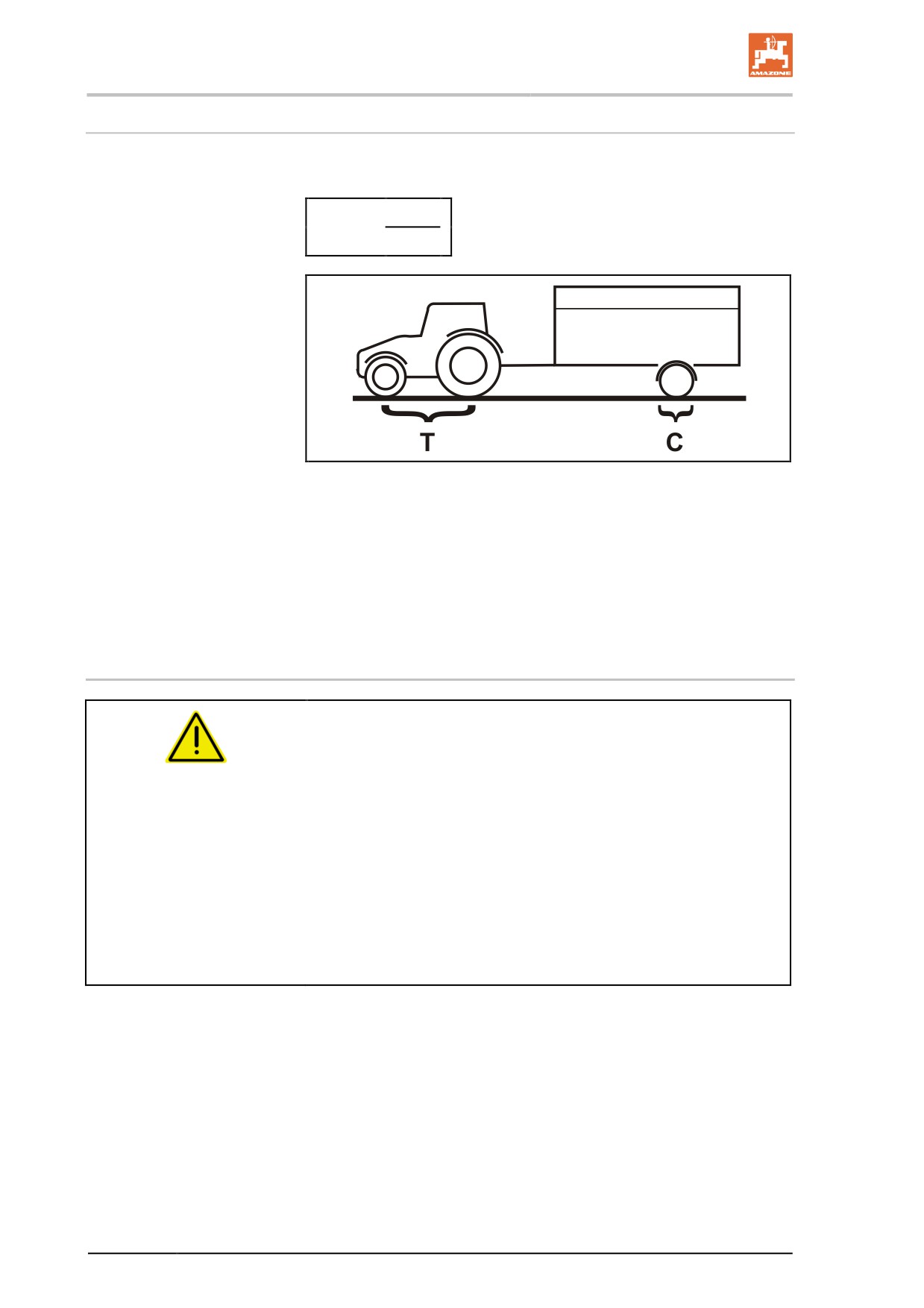
Calculate the actual DC value for the combination to be coupled
The actual DC value of a combination to be coupled is calculated as
follows:
T x C
DC = g x
T + C
Fig. 98
T: permissible total weight of your tractor in [t] (See tractor operat-
ing manual or vehicle documentation)
C: axle load of the implement [t] loaded with the permissible mass
without drawbar load (working load).
g: Gravity (9.81 m/s²)
7.1.3
Machines without their own brake system
WARNING
Risk of crushing, cutting, being caught or drawn in, or impact
through inadequate brake power of your tractor.
The tractor must achieve the brake rate specified by the tractor manu-
facturer, even with the machine connected.
If the machine does not possess its own brake system:
•
Then the actual tractor weight must be greater than or equal to
(≥) the actual weight of the connected machines.
In many countries, other regulations apply. In Russia, for exam-
ple, the weight of the tractor must be double that of the attached
machine.
•
The maximum operational speed is 25 km/h.
128
Commissioning
7.2
Adjusting the length of the PTO shaft to the tractor
WARNING
Danger from
•
damaged and/or destroyed, flying parts for the operator /
third party if the PTO shaft is compressed or pulls apart
while the machine coupled to the tractor is being
raised/lowered, because the length of the PTO shaft has not
been adjusted properly.
•
being caught and drawn in if the PTO shaft is installed in-
correctly or if unauthorised design changes are made.
Have the length of the PTO shaft checked in all operating positions by
a specialist workshop and, if necessary, adjusted before coupling the
PTO shaft to your tractor for the first time.
Always observe the operating manual supplied with the PTO shaft
when adjusting the PTO shaft.
This adjustment of the PTO shaft applies only for the current tractor
type. You may need to readjust the PTO shaft if you couple the ma-
chine to another tractor.
WARNING
Risk of being caught and drawn in if the PTO shaft is installed
incorrectly or if unauthorised design changes are made.
Only a specialist workshop may make design changes to the PTO
shaft. When doing so, read and follow the operating manual from the
manufacturer.
Adjusting the length of the PTO shaft is permitted with consideration
of the minimum profile overlap.
Design changes to the PTO shaft that are not described in the operat-
ing manual from the PTO shaft manufacturer are not permitted.
WARNING
Risk of crushing between the rear of the tractor and the machine
when raising and lowering the machine to determine the short-
est and longest operating position of the PTO shaft.
Only actuate the operator controls for the tractor's three-point linkage
•
from the intended workstation.
•
if you are outside of the danger area between the tractor and the
machine.
129
Commissioning
WARNING
Risk of crushing from unintentional:
•
rolling of the tractor and the connected machine.
•
lowering of the raised machine.
Secure the tractor and machine from unintentionally starting or rolling
and secure the raised machine against unintentional lowering before
entering the danger zone between the tractor and raised machine in
order to adjust the PTO shaft.
The PTO shaft is at its shortest when it is horizontal. The PTO shaft is
at its longest when the machine is fully lifted.
1.
Couple the tractor to the machine (do not connect the PTO
shaft).
2.
Apply the tractor's parking brake.
3.
Determine the clearance height of the machine with the shortest
and longest operating position for the PTO shaft.
3.1 To do so, raise and lower the machine via the tractor's
three-point hydraulic system.
While doing so, actuate the manual controls for the tractor's
three-point hydraulic system on the rear of the tractor, from
the provided workstation.
4.
Secure the machine, lifted in the measured clearance height,
against unintentional lowering (for example, by supporting it or
hooking it to a crane).
5.
Secure the tractor from unintentional starting before entering the
danger area between the tractor and machine.
6.
When measuring the length and shortening the PTO shaft, read
and follow the operating manual from the PTO shaft manufactur-
er.
7.
Put the shortened halves of the PTO shaft back together.
8.
Grease the universal joint shaft of the tractor and the gearbox
input shaft before connecting the PTO shaft.
The tractor symbol on the protective tube of the PTO shaft identi-
fies the tractor-side connection of the PTO shaft.
130
Commissioning
7.3
Securing tractor / machine against accidental starting and rolling
WARNING
Risk of crushing, shearing, cutting, being caught and/or drawn
in, or impact when making interventions in the machine, through
•
unintentional falling of the unsecured machine raised using
the tractor's three-point linkage.
•
unintentional falling of raised, unsecured machine parts.
•
unintentional start-up and rolling of the tractor-machine
combination.
•
Secure the tractor and the machine against unintentional start-
up and rolling before making any intervention in the machine.
•
It is forbidden to make any intervention in the machine, such as
installation, adjustment, troubleshooting, cleaning, maintenance
and repairs
ο when the machine is running
ο for as long as the tractor engine is running with a connect-
ed PTO shaft / hydraulic system.
ο when the ignition key is inserted in the tractor and the trac-
tor engine with the connected PTO shaft / hydraulic system
could be started unintentionally.
ο when the tractor and machine are not secured against un-
intentional rolling using their parking brakes and/or wheel
chocks.
ο when moving parts are not locked against unintentional
movement.
When carrying out such work, there is a high risk of contact with
unsecured components.
1.
Lower the raised, unsecured machine / raised, unsecured parts
of the machine.
→
This is how to prevent unintentional falling:
2.
Shut down the tractor engine.
3.
Remove the ignition key.
4.
Apply the tractor's parking brake.
5.
Secure the machine against unintentional rolling (only attached
machine)
ο On flat ground using the parking brake (if present) or wheel
chocks.
ο On uneven ground or slopes using the parking brake and
wheel chocks.
131
Commissioning
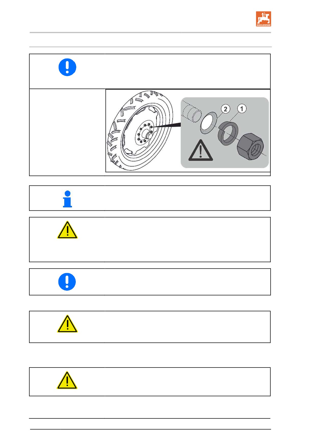
7.4
Fitting wheels
To assemble the wheels, use:
(1)
conical rings in front of the wheel nuts.
(2)
only rims with a fitting countersink for the conical ring.
If the machine is fitted with inflatable spare tyres, running wheels must
be fitted before putting into operation.
WARNING
•
Only one permitted set of tyres may be used, as specified in
the technical data (see page 54).
•
Wheel rims that are suitable for the tyres used must have a
rim that has been fully welded all the way round.
A hydraulic stand extension and ladder extension must be fitted in the
case of tyres with a diameter greater than 1860 mm.
1. Lift machine slightly using lifting crane.
DANGER
Use the attachment points marked for lifting belts.
See also "Loading" section, page 38.
2. Loosen wheel nuts on the inflatable spare tyres.
3. Remove inflatable spare tyres.
CAUTION
Take care when removing the inflatable spare tyres and putting
the running wheels in place.
4. Place the running wheels on threaded bolts.
5. Tighten wheel nuts.
132
Commissioning
Required tightening torque for wheel nuts: 510 Nm.
6. Lower machine and remove lifting belts.
7. After 10 operating hours, tighten wheel nuts.
7.5
Initial operation of service brake system
Perform a brake test while the trailed sprayer is empty, and again
when it is loaded to test the braking behaviour of the tractor with cou-
pled trailed sprayer.
We recommend that you have a specialist workshop coordinate the
brakes on the tractor and trailed sprayer in order to attain optimum
braking and minimum wear to brake linings (see "Maintenance" sec-
tion, page 197).
133
Commissioning
7.6
Adjusting the hydraulic system with the system setting screw
Only with Profi folding:
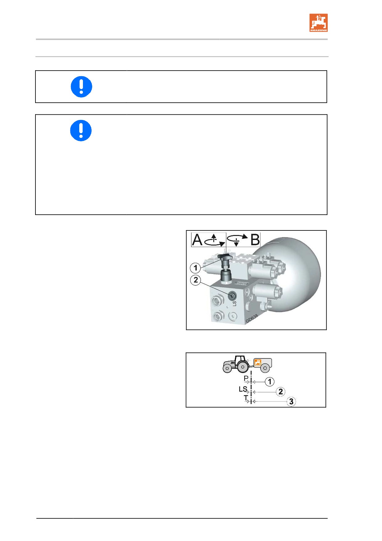
The hydraulic block is located at the front right on the implement be-
hind the cover plate.
•
Be sure to match the hydraulic systems of the tractor and the
implement.
•
The implement hydraulic system is adjusted using the system
setting screw on the hydraulic block of the implement.
•
Elevated hydraulic oil temperatures are the result of incorrect
adjustment of the system setting screw, caused by persistent
strain on the pressure relief valve of the tractor hydraulic system.
•
Adjustments may only be made in a pressureless state!
•
If there are hydraulic malfunctions between the tractor and the
implement during start-up, please contact your service partner.
(1) System setting screw can be adjusted in
position A and B
(2) LS connection for the load sensing control
line
Fig. 99
Implement-side connections in compliance with
ISO15657:
(1) P - feed line, pressure line, plug standard
width 20
(2) LS - control line, plug standard width 10
(3) T - return line, socket standard width 20
Fig. 100
134
Commissioning
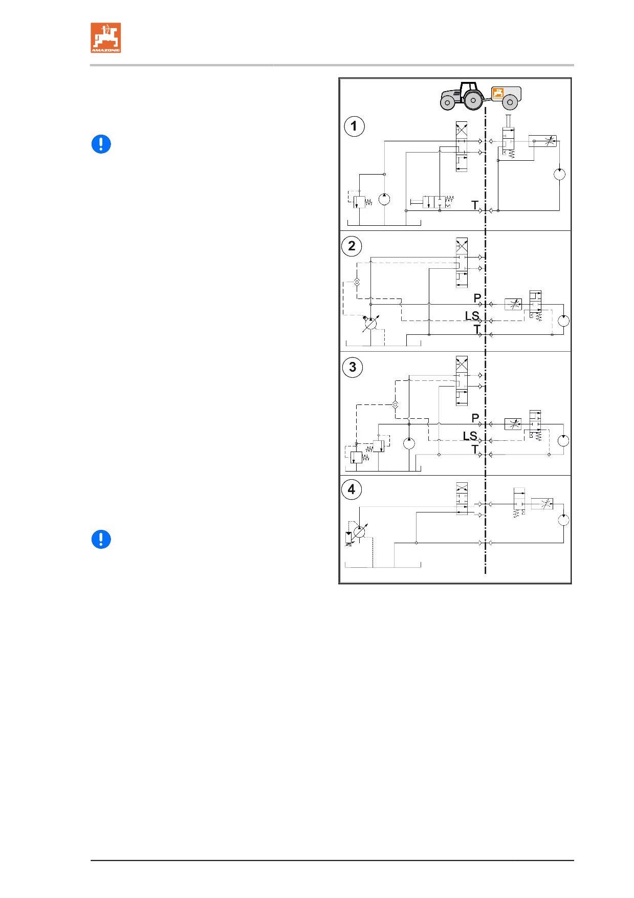
(1) Open-Center hydraulic system with con-
stant flow pump (gear pump) or setting
pump.
→ Put the system setting screw in position A.
Setting pump: Set the maximum required oil
quantity on the tractor control unit. If the oil
quantity is insufficient, correct functioning of
the implement cannot be ensured.
(2) Load-Sensing hydraulic system (pressure-
and flow-regulated setting pump) with direct
load sensing pump connection and LS set-
ting pump.
→ Put the system setting screw in position B.
(3) Load-Sensing hydraulic system with con-
stant flow pump (gear pump).
→ Put the system setting screw in position B.
(4) Closed-Center hydraulic system with pres-
sure-regulated setting pump.
→ Put the system setting screw in position B.
Risk of overheating of the hydraulic system:
the Closed-Center hydraulic system is less
suitable for the operation of hydraulic mo-
tors.
Fig. 101
135
Commissioning
7.7
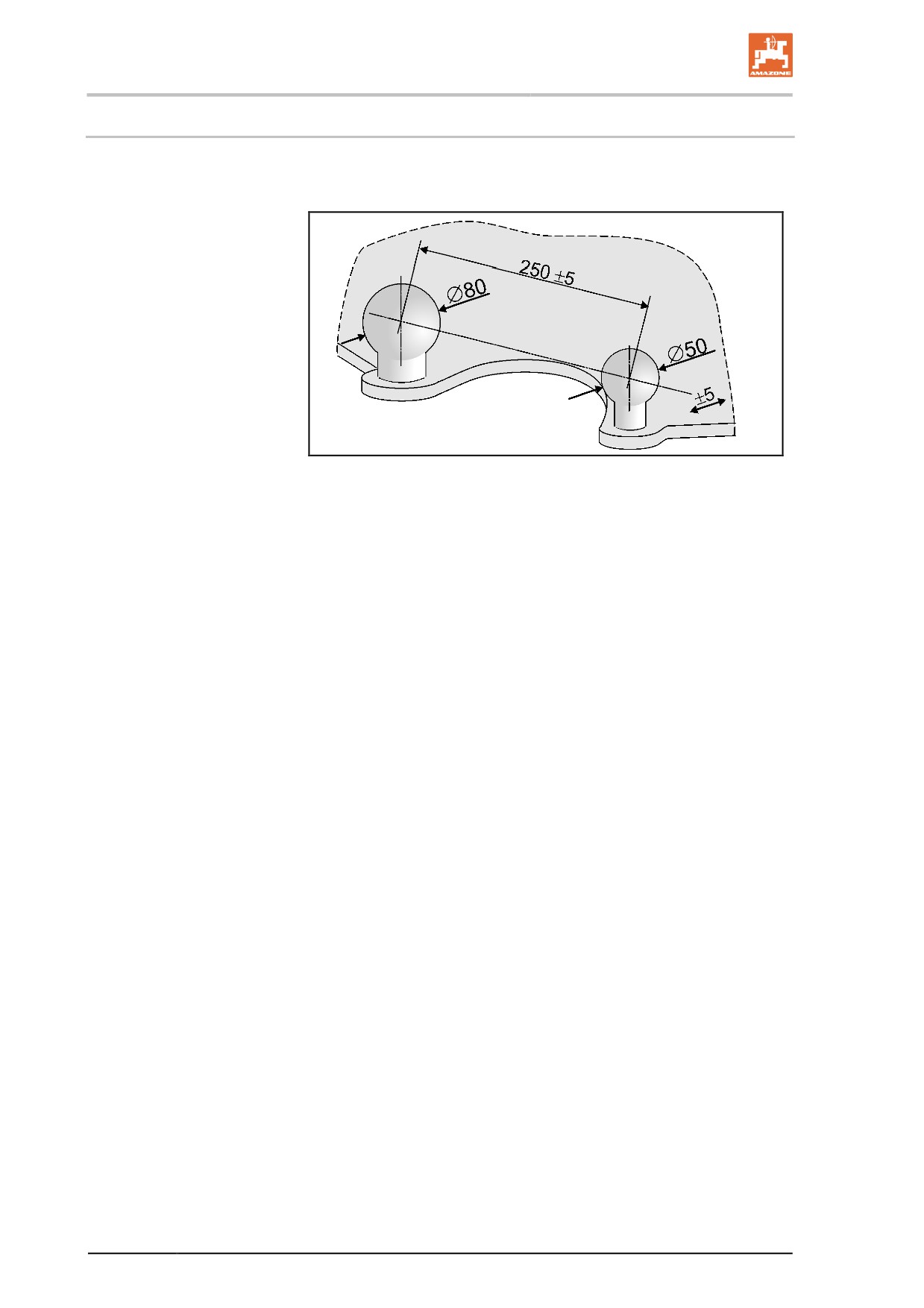
Rotation angle sensor - DoubleTrail
To use DoubleTrail, the tractor has to be fitted with a ball head cou-
pling 50 as specified in ISO 26402 for the steering unit.
Fig. 102
136
Coupling and uncoupling the machine
8
Coupling and uncoupling the machine
When coupling and decoupling the machine, comply with the section
"Safety information for the user", page 28.
WARNING
Risk of crushing from unintentional starting and rolling of the
tractor and machine when coupling or uncoupling the machine.
When coupling or decoupling the machine, secure the tractor and
machine against unintentional start-up and rolling before entering the
danger area between the tractor and machine; refer to page 131.
8.1
Coupling the machine
WARNING
Risk of breaking during operation, insufficient stability and in-
sufficient tractor steering and braking power from improper use
of the tractor.
You may only connect the machine to tractors suitable for this pur-
pose. Refer to the section "Checking the suitability of the tractor",
page 121.
WARNING
Risk of crushing when coupling the machine and standing be-
tween the tractor and the machine.
Instruct people to leave the danger area between the tractor and the
machine before you approach the machine.
Any helpers may only act as guides standing next to the tractor and
the machine, and may only move between the vehicles when both are
at a standstill.
WARNING
Risk of crushing, being caught or pulled in, or impact when the
machine is unexpectedly released from the tractor.
Use the intended equipment to connect the tractor and the machine in
the proper way.
137
Coupling and uncoupling the machine
WARNING
Risk of energy supply failure between the tractor and the ma-
chine due to damaged power supply lines.
During coupling, check the course of the power supply lines. The
power supply lines
•
must give slightly to all movement of the connected machine
without tensioning, kinking or rubbing.
•
must not chafe against other parts.
1. Direct people away from the danger area between the tractor
and machine before you approach the machine with the tractor.
2. Couple the supply lines first before coupling the machine with
the tractor.
2.1 Drive the tractor up to the machine, leaving a clearance of
approximately 25 cm between tractor and machine.
2.2 Secure the tractor against unintentional starting and unin-
tentional rolling.
2.3 Check whether the universal joint shaft of the tractor is
switched off.
2.4 Couple the PTO shaft and supply lines with the tractor.
2.5 Hydraulic brake: fasten the parking brake pulling cable to
the tractor.
3. Now reverse the tractor towards the machine so that the con-
nection fitting can be coupled.
4. Couple the connection fitting.
5. Lift the stand into transport position.
6. Remove wheel chocks, release parking brake.
When taking a corner with the machine hooked up for the first time,
please make sure that no attachment on the tractor collide with the
machine.
138
Coupling and uncoupling the machine
8.2
Uncoupling the machine
WARNING
Risk of crushing, cutting, being caught or drawn in, or impact
through inadequate stability and tipping over of the uncoupled
machine.
Park the empty machine on a horizontal space with a hard surface.
When uncoupling the machine, there must always be enough space
in front of the machine so that you can align the tractor with the ma-
chine if necessary.
1. Park the empty machine on a horizontal space with a hard sur-
face.
2. Uncouple the machine from the tractor.
2.1 Secure the machine against unintentionally rolling. See
page 131.
2.1 Lower the stand to the parking position.
2.2 Uncouple the connection fitting.
2.3 Draw the tractor forwards by approximately 25 cm.
→ The space created between the tractor and the machine al-
lows better access for decoupling the PTO shaft and the
power supply lines.
2.4 Secure the tractor and machine against unintentional start-
ing and unintentional rolling.
2.5 Decouple the PTO shaft.
2.6 Place the PTO shaft in the holder.
2.7 Uncouple the supply lines.
2.8 Fasten the supply lines in the corresponding parking sock-
ets.
2.9 Hydraulic brake: detach parking brake pulling cable from
tractor.
139
Coupling and uncoupling the machine
8.2.1
Manoeuvring the uncoupled machine
DANGER
You must be particularly careful when shunting the machine with
the service brake system released, since only the manoeuvring
vehicle is now braking the trailed sprayer.
The machine must be connected to the manoeuvring vehicle
before you actuate the release valve on the trailer brake valve.
The manoeuvring vehicle must be braked.
The service brake system cannot be released using the release valve
if the air pressure in the air reservoir drops below 3 bar (e.g. if the
release valve has been actuated multiple times or if there are leaks in
the brake system).
To release the service brake
•
fill the air reservoir.
•
Remove all air from the braking system at the drain valve on the
air reservoir.
1. Connect the machine to the manoeuvring vehicle.
2. Brake the manoeuvring vehicle.
3. Remove the wheel chocks and release the parking brake.
4. pneumatic braking system only:
4.1 Press the actuator button on the release valve as far as it
will go (see page 68).
→ The service brake system is released and the machine can be
manoeuvred.
4.2 Once the manoeuvring procedure is finished, pull out the
actuator button on the release valve as far as it will go.
→ The pressure from the air reservoir brakes the trailed sprayer
again.
5. Actuate the brakes on the manoeuvring vehicle again once you
have finished manoeuvring the machine.
6. Tighten the parking brake again and secure the machine against
rolling with wheel chocks.
7. Uncouple the machine and manoeuvring vehicle.
Before the implement can be manoeuvred in reverse, the rear axle
must be locked in the straight position.
Close the stop tap on the hydraulic block.
140
Transportation
9
Transportation
•
During transportation, follow the instructions given in the section
"Safety instructions for the operator", page 30.
•
Before moving off, check:
ο that the supply lines are connected correctly.
ο the lighting system for damage, proper operation and
cleanliness,
ο the braking and hydraulic systems for obvious defects.
ο that the parking brake is completely released
ο the function of the brake system
WARNING
Risk of crushing, shearing, cutting, being caught and/or drawn
in, or impact when making interventions in the machine, through
unintentional machine movements.
•
On foldable machines, check that the transport locks are correct-
ly locked.
•
Secure the machine against unintentional movements before
starting transportation.
WARNING
Risk of crushing, cutting, being caught and/or drawn in, or im-
pact from tipping and insufficient stability.
•
Drive in such a way that you always have full control over the
tractor with the attached machine.
In so doing, take your personal abilities into account, as well as
the road, traffic, visibility and weather conditions, the driving
characteristics of the tractor and the connected machine.
WARNING
Risk of breaking during operation, insufficient stability and in-
sufficient tractor steering and braking power from improper use
of the tractor.
These risks pose serious injuries or death.
Comply with the maximum load of the connected machine and the
permissible axle and drawbar loads of the tractor. If necessary, drive
only with a partially filled tank.
141
Transportation
WARNING
Risk of falling when riding on the machine, contrary to instruc-
tions.
It is forbidden to ride on the machine and/or climb the machine while
it is running.
Instruct people to leave the loading site before approaching the ma-
chine.
CAUTION
•
During transportation, follow the instructions given in the section
"Safety instructions for the operator", page 30.
•
Transportation is prohibited with a locked tractor control unit. As
a general rule, put the tractor control unit on the tractor into neu-
tral for transportation.
•
Move the sprayer boom to the transport position and secure
mechanically.
→
If a working width reduction of the outer elements is mounted,
unfold it for transporting purposes..
•
Use transport locking for locking the folded-in sprayer boom in its
transport position to prevent it from folding out unintentionally
•
Use the transport safety catch to secure the induction bowl when
it has been swivelled up into its transport position to prevent it
from swivelling down again accidentally.
•
Use transport locking for locking the raised ladder to prevent it
from folding down again accidentally.
•
Securing elements engage the catching hooks and secure the
ladder in the transport position against unintentional lowering.
•
If a boom extension (option) is mounted, move it into the
transport position.
•
Switch the work lights off during transport to avoid blinding other
motorists.
DANGER
Risk of accident from instable driving conditions
Secure the oil supply from the tractor so that the hydro-pneumatic
spring suspension can operate.
DoubleTrail:
Select the road steering mode on the DoubleTrail operating terminal!
SingleTrail:
For transportation journeys, align the rear swivel axle parallel to the
front axle.
To do this, actuate the corresponding tractor control unit natural.
142
Using the machine
10
Using the machine
When using the machine, observe the information in the following
sections:
•
"Warning symbols and other labels on the machine" starting on
page 19 and
•
"Safety information for the user", starting on page 28 ff.
Observing this information is important for your safety.
Observe the separate operating manual for the control terminal and
the implement control software.
WARNING
DistanceControl
Risk of injury due to accidental movement of the sprayer boom
in automatic mode when entering the radiation area of the radar
sensor.
Lock the sprayer boom
•
Before leaving the tractor.
•
If unauthorised persons are standing in the area of the sprayer
boom.
WARNING
Risk of breaking during operation, insufficient stability and in-
sufficient tractor steering and braking power from improper use
of the tractor.
Comply with the maximum load of the connected machine and the
permissible axle and drawbar loads of the tractor. If necessary, drive
only with a partially filled tank.
WARNING
Risk of crushing, cutting, being caught and/or drawn in, or im-
pact through insufficient stability and tipping of the tractor
and/or the attached machine.
Drive in such a way that you always have full control over the tractor,
whether the machine is attached or unattached.
In so doing, take your personal abilities into account, as well as the
road, traffic, visibility and weather conditions, the driving characteris-
tics of the tractor and the connected machine.
143
Using the machine
WARNING
Risk of crushing, shearing, cutting, being caught and/or drawn
in, or impact through
•
unintentional falling of raised, unsecured machine parts.
•
unintentional start-up and rolling of the tractor-machine
combination.
Secure the tractor and the machine against unintentional start-up and
rolling before eliminating faults on the machine. See page 131.
Wait for the machine to stop before entering the machine danger
area.
WARNING
Danger for the operator or third parties from damaged compo-
nents being ejected due to impermissibly high drive speeds of
the tractor universal joint shaft.
Observe the permissible machine drive speed before switching on the
tractor universal joint shaft.
WARNING
Risk of being caught and drawn in and danger from foreign ob-
jects being caught and thrown out in the danger area of the driv-
en PTO shaft.
•
Whenever the machine is used, first check to ensure that the
safety devices and guards of the PTO shaft are fully intact and
functional.
Have damaged safety devices and guards of the PTO shaft re-
placed immediately by a specialist workshop.
•
Check that the PTO shaft guard is secured against rotation by
the supporting chain.
•
Maintain a sufficient safety clearance between you and the driv-
en PTO shaft.
•
Direct people out of the danger area of the driven PTO shaft.
•
Shut down the tractor engine immediately in case of danger.
144
Using the machine
WARNING
Risk of accidental contact with crop protection agents / spray
liquid.
•
Wear personal protective equipment
ο when preparing the spray liquid.
ο when cleaning / replacing the spraying nozzles during
spraying operation.
ο for all cleaning work carried out on the field sprayer after
spraying operation.
•
When wearing the required protective clothing, always observe
the manufacturer's instructions, the product information, the user
manual, the safety datasheet or the operating manual for the
crop protection agent to be used. For example, use:
ο Chemical-resistant gloves
ο Chemical-resistant overalls
ο Water-resistant footwear
ο A face mask
ο Breathing apparatus
ο Safety glasses
ο Skin protection agents, etc.
WARNING
Risk to health from accidental contact with crop protection
agents or spray liquid.
•
Put on protective gloves before
ο using crop protection agent,
ο carrying out work on a contaminated field sprayer or
ο cleaning the field sprayer.
•
Wash the gloves with clear fresh water from the fresh water tank
ο immediately after contact with crop protection agent.
ο before removing the gloves.
•
To use Trail-Tron, open the stop tap on the hydraulic cylinder.
•
For load-sensing operation, open the stop tap on the load-
sensing control line.
145
Using the machine
10.1
Preparing for spraying operation
•
The field sprayer must be operating properly in order to guaran-
tee correct application of the crop protection agent. Have the
field sprayer tested regularly on a test rig. Rectify any deficien-
cies immediately.
•
Make sure of using the correct filter equipment, see page 88
•
Clean the field sprayer thoroughly before spreading a different
crop protection agent.
•
Flush the nozzle line before:
ο each time changing a nozzle.
ο before rotating the multiple-nozzle head to another nozzle.
See the section on "Cleaning", page 187
•
Fill the flushing water tank and the clear water tank.
146
Using the machine
10.2
Preparing the spray liquid
WARNING
Risk of accidental contact with crop protection agent and / or
spray liquid.
•
Always introduce the crop protection agent into the spray liquid
tank using the induction bowl.
•
Swivel the induction bowl into the filling position before pouring
in the crop protection agent.
•
Observe all safety regulations concerning physical protective
equipment and breathing apparatus to be used when handling
crop protection agents and preparing the spray liquid described
in the instructions for use of the crop protection agent.
•
Do not prepare the spray liquid in the vicinity of wells or surface
water.
•
Avoid leaks and contaminations involving crop protection agents
and/or spray liquids by taking proper care and by wearing the
appropriate physical protection equipment.
•
To avert risks to third parties, do not leave any prepared spray
liquid, unused crop protection agent, as well as used crop pro-
tection agent canisters and the used field sprayer unattended.
•
Protect contaminated crop protection agent canisters and the
contaminated field sprayer from precipitation.
•
During and after preparing the spray liquid, provide for sufficient
cleanliness to keep contamination risks as low as possible (e.g.
thoroughly wash used gloves before removing them and dispose
of the washing water and cleaning fluid in the proper manner).
DANGER
Risk of accident from instable driving conditions
Secure the oil supply from the tractor so that the hydro-pneumatic
spring suspension can operate.
•
The prescribed water and agent spray rate can be found in the
directions for use of the crop protection agent.
•
Please read intently the directions for use of the agent and ob-
serve the specified precautions!
147
Using the machine
WARNING
Danger for people and animals from accidental contact with the
spray liquid while filling the spray liquid tank!
•
Wear personal protective equipment when handling crop protec-
tion agents or dumping spray liquids from the spray liquid tank.
The type of personal protective equipment required is described
in the manufacturer's instructions, the product information, the
directions for use, the safety data sheet or the user manual for
the crop protection agent in question.
•
Never leave the field sprayer unattended while filling.
ο Never fill the spray liquid tank beyond the nominal volume.
ο When filling the spray liquid tank, never exceed the permis-
sible load of the field sprayer. Pay attention to the respec-
tive specific weight of the liquid in question.
ο While filling, keep watch on the fill level indicator to avoid
overfilling the spray liquid tank.
ο While filling the spray liquid tank, pay particular attention to
the sealed surfaces; no spray liquid must be allowed to get
into the sewerage system.
•
Before each filling, check the field sprayer for damage, e.g. for
leaking tanks and hoses, as well as for the correct positioning of
all control elements.
While filling, pay attention to the permissible load capacity of your field
sprayer. Always take the differing specific weights [kg/l] for the indi-
vidual liquids into account while filling your field sprayer.
Specific weights of different liquids
Liquid
Water
Urea
UAN
NP solution
Density [kg/l]
1
1.11
1.28
1.38
Control terminal:
In the control terminal, call up the filling display from the Job menu.
148
Using the machine
•
As it is difficult to dispose of residues in an environmentally-
friendly manner, carefully calculate the required filling quantity or
refill quantity to avoid leaving any residue at the end of the
spraying operation.
ο To calculate the required refill quantity for final filling of the
spray liquid tank, use the "Filling table for remaining spray
area". To do this, subtract the technical, undiluted residue
in the sprayer boom from the calculated refill quantity!
Refer to the section "Filling table for remaining areas".
Procedure
1. Determine the required water and agent spray rate by consulting
the directions for use of the crop protection agent.
2. Calculate the filling quantity or refill quantity for the area to be
treated.
3. Fill the machine and blend in the agent.
4. Agitate the spray liquid before commencing spraying operations
in accordance with the instructions of the spraying agent manu-
facturer.
Fill the machine preferably using a suction hose and blend in the
agent while filling.
The induction area is thereby flushed with water constantly.
•
During the filling process, start blending in the agent once the
tank filling level has reached more than 20%.
•
When using more than one agent:
ο Clean the canister immediately after each induction of an
agent.
ο Flush the induction port after each induction of an agent.
•
When filling, no foam must escape from the spray liquid tank.
The addition of a froth-inhibiting agent also prevents the spray
liquid tank from frothing over.
The machine has been fitted with an automatic filling stop, which
terminates the filling process when the requested filling quantity has
been reached.
The agitators normally remain switched on from the initial filling to the
end of the spraying operation. The instructions of the agent manufac-
turer, however, have priority.
149
Using the machine
•
With the agitator running, feed the water-soluble plastic film bag
directly into the spray liquid tank.
•
Before spraying, fully dissolve the urea by circulating the liquid.
When dissolving large quantities of urea, the temperature of the
spray liquid falls more sharply; the urea consequently dissolves
more slowly. The warmer the water, the faster and more com-
pletely the urea can dissolve.
•
Carefully wash the empty agent canisters, render them unusa-
ble, collect and dispose of them in a proper manner. Do not re-
use them for other purposes.
•
If only spray liquid is available for washing the agent canisters,
first use this to carry out preliminary cleaning. Then wash them
meticulously when clear fresh water is available, e.g. before pre-
paring the next load for the spray liquid tank or when diluting the
residue from the last load.
•
Carefully wash out the empty agent tank (e.g. using canister
flushing) and add the flushing water to the spray liquid!
High degrees of water hardness above 15° dH (German degrees of
hardness) can lead to lime deposits, which may impede the function-
ing of the implement and must be removed at regular intervals.
150
Using the machine
10.2.1
Calculating the filling and refill quantity
To calculate the required refill quantity for the final filling of the spray
liquid tank, use the "Filling table for remaining spray area", page
102165.
Example 1:
The following are given factors:
Tank nominal volume
1000 l
Residue in the tank
0 l
Water consumption
400 l/ha
Agent required per ha
Agent A
1.5 kg
Agent B
1.0 l
Question:
How many litres of water, how many kg of Agent A and how many
litres of Agent B must be used to treat a surface of 2.5 ha in area?
Answer:
Water:
400 l/ha
x
2.5 ha
=
1000 l
Agent A:
1.5 kg/ha
x
2.5 ha
=
3.75 kg
Agent B:
1.0 l/ha
x
2.5 ha
=
2.5 l
Example 2:
The following are given factors:
Tank nominal volume
1000 l
Residue in the tank
200 l
Water consumption
500 l/ha
Recommended concentration
0.15 %
Question 1:
How many litres or kg of agent are needed to fill the tank?
Question 2:
How large is the area to be treated in ha if a residue of 20 l remains in
the tank after spraying?
151
Using the machine
Formula and answer to Question 1:
Refill amount of water [l] x concentration [%]
= Addition of agent [l or kg]
100
(1000 - 200) [l] x 0.15 [%]
=
1.2 [l or kg]
100
Formula and answer to Question 2:
Quantity of liquid available [l] - residue [l]
= Area to be treated [ha]
Water consumption [l/ha]
1000 [l] (tank nominal volume) - 20 [l] (residue)
=
1.96 [ha]
500 [l/ha] water consumption
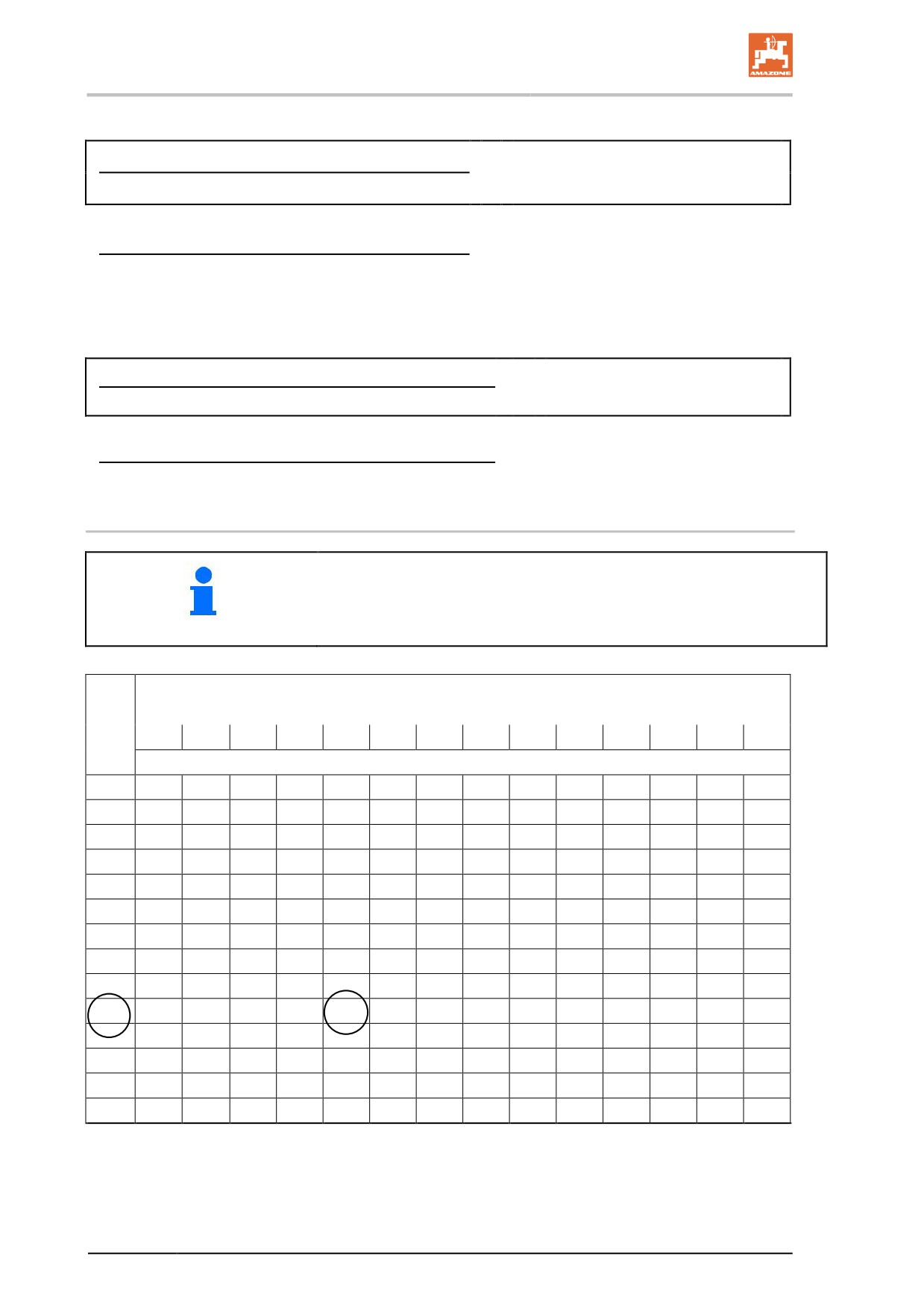
10.2.2 Filling table for remaining spray area
•
The specified re-fill quantities apply for an application rate of 100
l/ha. For other application rates, the re-fill quantity increases by a
multiple.
•
Take account of the residual quantity in the boom.
Working width [m]
Dis-
tance
15
16
18
20
21
24
27
28
30
32
33
36
39
40
[m]
Refill quantity [l]
10
2
2
2
2
2
2
3
3
3
3
3
4
4
4
20
3
3
4
4
4
5
5
6
6
6
7
7
8
8
30
5
5
5
6
6
7
8
8
9
10
10
11
11
12
40
6
7
7
8
8
10
11
11
12
13
13
14
15
16
50
8
8
9
10
11
12
14
14
15
16
17
18
19
20
60
9
10
11
12
13
14
16
17
18
19
20
22
23
24
70
11
11
13
14
15
17
19
20
21
22
23
25
27
28
80
12
13
14
16
17
19
22
22
24
26
26
29
30
32
90
14
15
16
18
19
22
24
25
27
29
30
32
34
36
100
15
16
18
20
21
24
27
28
30
32
33
36
38
40
200
30
32
36
40
42
48
54
56
60
64
66
72
74
80
300
45
48
54
60
63
72
81
84
90
96
99
108
114
120
400
60
64
72
80
84
96
108
112
120
128
132
144
152
160
500
75
80
90
100
105
120
135
140
150
160
165
180
190
200
Fig. 103
152
Using the machine
10.2.3 Fill the spray liquid tank via the suction port and blend in the agent at the
same time
Preferably perform the filling from a suitable container and not from
an open water access point.
WARNING
Damage to the suction valve chest caused by pressure filling via the
suction connection!
The suction connection is not suitable for pressure filling. This also
applies for filling from a higher-elevation source.
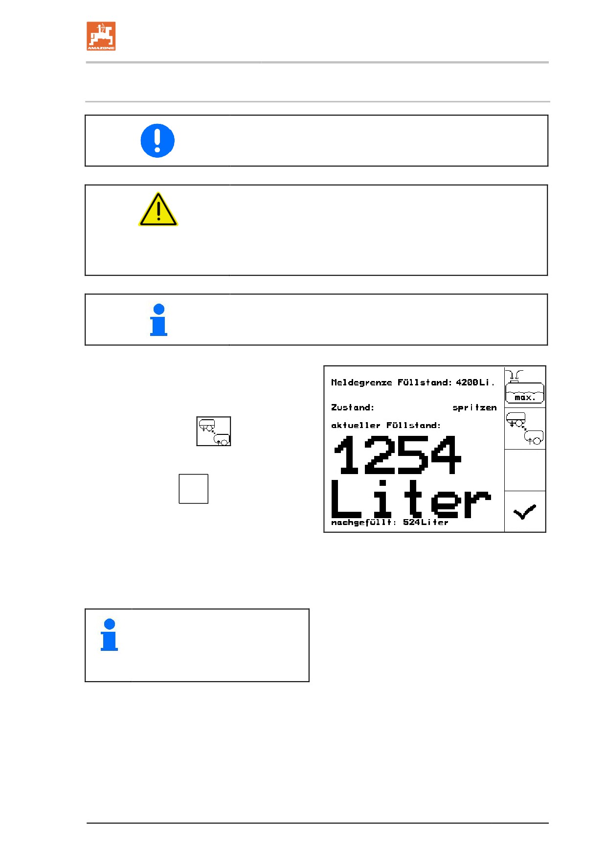
In the operating terminal, call up the filling display in the Work menu in
order to enter the re-filling quantity and make use of the automatic
filling stop.
1. Connect the suction hose to the filling con-
nection and water access point.
2. Drive the pump (at least
400 rpm) and fill the container.
3. Operating terminal:
Set suction port
to suction via suction coupling /
Press the suction port button G, suction
port in position
→ The tank is filled automatically up the signal
limit.
Fig. 104
→ Pressing the button again terminates the
filling process prematurely.
Fig. 105
•
The filling level report limit has to
be entered correctly!
•
The filled container is indicated
by an acoustic signal.
153