Amazone UX 11200 Trailed field sprayer. Operating Manual (2017) - page 1
Operating Manual
az
UX 11200
Trailed field sprayer
Please read this operating
MG4495
manual before commissioning.
BAG0101.9 11.17
Keep it in a safe place
Printed in Germany
for future use
en
Table of Contents
1
User Information
11
1.1
Purpose of the document
11
1.2
Locations in the operating manual
11
1.3
Diagrams
11
2
General safety instructions
12
2.1
Obligations and liability
12
2.2
Representation of safety symbols
14
2.3
Organisational measures
15
2.4
Safety and protection equipment
15
2.5
Informal safety measures
15
2.6
User training
16
2.7
Safety measures in normal operation
16
2.8
Danger from residual energy
17
2.9
Maintenance and repair work, fault elimination
17
2.10
Design changes
17
2.10.1
Spare and wear parts and aids
18
2.11
Cleaning and disposal
18
2.12
User workstation
18
2.13
Warning symbols and other signs on the machine
19
2.13.1
Positions of warning symbols and other labels
20
2.14
Potential risks from not observing the safety instructions
27
2.15
Safety-conscious working
27
2.16
Safety information for users
28
2.16.1
General safety and accident prevention information
28
2.16.2
Hydraulic system
31
2.16.3
Electrical system
32
2.16.4
Universal joint shaft operation
33
2.16.5
Coupled machines
34
2.16.6
Brake system
34
2.16.7
Tyres
35
2.16.8
Field sprayer operation
36
2.16.9
Cleaning, maintenance and repairs
37
3
Loading and unloading
38
4
Product description
40
4.1
Overview of the assemblies
40
4.2
Safety and protection equipment
42
4.3
Liquid circuit
43
4.4
Supply hoses between the tractor and the machine
44
4.5
Transportation equipment
44
4.6
Intended use
45
4.7
Regular device inspections
46
4.8
Consequences of using certain crop protection agents
46
4.9
Danger areas and danger points
47
4.10
Rating plate and CE mark
48
4.11
Conformity
48
4.12
Maximum permissible application rate
49
4.13
Technical Data
50
4.13.1
asic implement
50
4.13.2
Residual amounts
51
4.13.3
Weights basic machine and modules
53
4.13.4
Permissible total weight and tyres
54
4.14
Noise emissions data
55
6
Table of Contents
4.15
Required tractor equipment
56
5
Construction and function of the basic machine
57
5.1
Functionality
57
5.2
Control terminal
58
5.3
PTO shaft
61
5.3.1
Coupling the PTO shaft
63
5.3.2
Uncoupling the PTO shaft
64
5.4
Hydraulic connections
65
5.4.1
Coupling hydraulic hose lines
66
5.4.2
Disconnecting hydraulic hose lines
67
5.5
Air pressure brake system
68
5.5.1
Automatic load-dependent braking force regulator (ALB)
69
5.5.2
Coupling the brake system
70
5.5.3
Uncoupling the brake system
71
5.6
Hydraulic service brake system
72
5.6.1
Coupling the hydraulic service brake system
72
5.6.2
Uncoupling the hydraulic service brake system
72
5.6.3
Emergency brake
72
5.7
Parking brake
74
5.8
Foldable wheel chocks
75
5.9
Safety chain for implements without brake system
76
5.10
Tandem axle
77
5.11
Hydropneumatic sprung suspension (optional)
78
5.12
Hydraulic stand
78
5.13
Spray liquid tank
79
5.13.1
Agitators
80
5.13.2
Maintenance platform with ladder
81
5.13.3
Suction port for filling the spray liquid tank (optional)
82
5.13.4
Filling connection for filling the spray liquid tank with pressure (option)
82
5.14
Flushing water tank
83
5.15
Induction bowl with canister flushing
84
5.16
Filling connection for Ecofill (optional)
85
5.17
Fresh water tank
86
5.18
Pump equipment
87
5.18.1
Hydraulic pump drive
87
5.19
Filter equipment
88
5.19.1
Filling sieve
88
5.19.2
Suction filter
88
5.19.3
Self cleaning pressure filter
89
5.19.4
Nozzle filters
89
5.19.5
Bottom sieve in the induction bowl
90
5.20
Transport and secure container (optional)
90
5.21
Crop protection underside (optional)
90
5.22
Exterior wash down kit (optional)
91
5.23
Camera system
92
5.24
Work floodlights
93
5.25
Comfort equipment
94
5.26
Operating terminal
95
5.27
AmaPilot / AmaPilot+ multi-function stick
96
6
Construction and function of the sprayer boom
97
6.1
Super-L boom
101
6.1.1
Spacer
102
6.2
Working with the sprayer boom folded out on one side
103
6.3
Reduction joint on the outer boom (optional)
104
7
Table of Contents
6.4
Boom width reduction (option)
105
6.5
Boom extension (option)
106
6.6
Hydraulic tilt adjustment (optional)
107
6.7
Distance control (optional)
107
6.8
Spray lines
108
6.8.1
Single nozzles
110
6.8.2
Multi nozzles (optional)
110
6.8.3
Electric boundary nozzles (optional)
112
6.8.4
Electric end nozzle switching (optional)
112
6.8.5
Electric additional nozzle switching (optional)
112
6.9
Automatic single nozzle control (optional)
113
6.9.1
Single nozzle control AmaSwitch
113
6.9.2
4-way AmaSelect single nozzle control
113
6.10
Special optional equipment for liquid fertiliser
115
6.10.1
Three-ray nozzles (optional)
115
6.10.2
Line filter for spray lines
116
6.10.3
7 hole nozzles / FD nozzles (optional)
117
6.11
Foam marker (optional)
118
6.12
Lift module
119
7
Commissioning
120
7.1
Checking the suitability of the tractor
121
7.1.1
Calculating the actual values for the total tractor weight, tractor axle loads and tyre load
capacities, as well as the minimum ballast
121
7.1.2
Requirements for tractor operation with attached machines
125
7.1.3
Machines without their own brake system
128
7.2
Adjusting the length of the PTO shaft to the tractor
129
7.3
Securing tractor / machine against accidental starting and rolling
131
7.4
Fitting wheels
132
7.5
Initial operation of service brake system
133
7.6
Adjusting the hydraulic system with the system setting screw
134
7.7
Rotation angle sensor - DoubleTrail
136
8
Coupling and uncoupling the machine
137
8.1
Coupling the machine
137
8.2
Uncoupling the machine
139
8.2.1
Manoeuvring the uncoupled machine
140
9
Transportation
141
10
Using the machine
143
10.1
Preparing for spraying operation
146
10.2
Preparing the spray liquid
147
10.2.1
Calculating the filling and refill quantity
151
10.2.2
Filling table for remaining spray area
152
10.2.3
Fill the spray liquid tank via the suction port and blend in the agent at the same time
153
10.2.4
Adding the agent using Ecofill
156
10.2.5
Filling the spray liquid tank via the filling connection and blending in the agent
157
10.3
Spraying operation
160
10.3.1
Applying the spray liquid
162
10.3.2
Drift reduction measures
164
10.3.3
Dilute the spray liquid with flushing water
164
10.4
Residues
165
10.4.1
Diluting the excess residue in the spray liquid tank and spraying out the diluted residue
remaining at the end of spraying operations
166
10.4.2
Emptying the spray liquid tank using the pump
167
10.5
Cleaning the field sprayer
168
10.5.1
Cleaning the sprayer with the tank empty
169
10.5.2
Intensive cleaning of the sprayer during a critical agent change
170
8
Table of Contents
10.5.3
Performing chemical cleaning
171
10.5.4
Draining the final residues
172
10.5.5
Cleaning the suction filter when tank is empty
173
10.5.6
Cleaning the suction filter when tank is full
174
10.5.7
Cleaning the pressure filter when the tank is empty
175
10.5.8
Cleaning the pressure filter when the tank is full
175
10.5.9
Exterior cleaning
176
10.5.10
Cleaning the sprayer with a full tank (work interruption)
177
11
Double Trail
178
11.1
Operating terminal
178
11.2
Road use
180
11.3
Field operation
180
11.3.1
Switching field mode on and off
180
11.3.2
Steering program - track following steering system
181
11.3.3
Steering program - manual operation
182
11.4
Axle synchronisation
182
11.5
Tests and faults
183
11.5.1
Startup test
183
11.5.2
Fault lamp and fault buzzer
183
11.5.3
Fault memory
183
12
Faults
184
13
Cleaning, maintenance and repair
185
13.1
Cleaning
187
13.2
Winter storage and long periods out of operation
188
13.3
Lubrication specifications
190
13.3.1
Lubrication point overview
191
13.4
Maintenance schedule - overview
194
13.5
Axle and brake
197
13.5.1
Hydraulic brakes
202
13.6
Parking brake
203
13.7
Tyres / wheels
204
13.7.1
Tyre pressures
204
13.7.2
Fitting tyres
205
13.8
Check the coupling device
206
13.9
Hydropneumatic sprung suspension
207
13.10
Drawbar
207
13.11
Hydraulic system
208
13.11.1
Labelling hydraulic hose lines
209
13.11.2
Maintenance intervals
209
13.11.3
Inspection criteria for hydraulic hose lines
209
13.11.4
Installation and removal of hydraulic hose lines
210
13.11.5
Fluid filter
211
13.11.6
Cleaning the solenoid valves
211
13.11.7
Clean / exchange the filter in the hydraulic plug
212
13.11.8
Hydro-pneumatic pressure reservoir
212
13.11.9
Adjusting the hydraulic throttle valve
213
13.12
Pump
215
13.12.1
Check the oil level
215
13.12.2
Changing the oil
215
13.12.3
Cleaning
215
13.12.4
Checking and replacing the suction and pressure-side valves
216
13.12.5
Checking and replacing the piston diaphragm
217
13.13
Checking and exchanging the pressure reservoir diaphragm (workshop task)
218
13.14
Calibrate the flow meter
218
13.15
Eliminating limescale in the system
219
13.16
Field sprayer calibration
220
9
Table of Contents
13.17
Nozzles
222
13.17.1
Fitting the nozzle
222
13.17.2
Removing the diaphragm valve if the nozzle is dripping
222
13.18
Line filter
223
13.19
Instructions on testing the field sprayer
224
13.20
Screw tightening torques
226
13.21
Disposing of the field sprayer
227
14
Spray table
228
14.1
Spray tables for flat-fan, anti-drift, injector and airmix nozzles, spraying height 50 cm
228
14.2
Spraying nozzles for liquid manure
232
14.2.1
Spray table for three-ray nozzle, spraying height 120 cm
232
14.2.2
Spray table for 7-hole nozzles
234
14.2.3
Spray table for FD nozzles
235
14.3
Spray table for drag hose unit
237
14.4
Conversion table for spraying ammonium nitrate / urea solution (AUS) liquid fertiliser
239
10
User Information
1
User Information
The User Information section provides information on use of the oper-
ating manual.
1.1
Purpose of the document
This operating manual
•
describes the operation and maintenance of the machine.
•
provides important information on safe and efficient handling of
the machine.
•
is a component part of the machine and should always be kept
with the machine or the towing vehicle.
•
Keep it in a safe place for future use.
1.2
Locations in the operating manual
All the directions specified in the operating manual are always seen in
the direction of travel.
1.3
Diagrams
Instructions and responses
Activities to be carried out by the user are given as numbered instruc-
tions. Always keep to the order of the instructions. The response to an
instruction is given by an arrow. Example:
1. Instruction 1
→ Machine response to instruction 1
2. Instruction 2
Lists
Lists without an essential order are shown as a list with bullets. Ex-
ample:
•
Point 1
•
Point 2
Item numbers in diagrams
Numbers in round brackets refer to items in diagrams. The first num-
ber refers to the diagram and the second number to the item.
Example: (Fig. 3/6)
•
Figure 3
•
Item 6
11
General safety instructions
2
General safety instructions
This section contains important information on safe operation of the
machine.
2.1
Obligations and liability
Comply with the instructions in the operating manual
Knowledge of the basic safety information and safety regulations is a
basic requirement for safe handling and fault-free machine operation.
Obligations of the operator
The operator is obliged only to let those people work with/on the ma-
chine who
•
are aware of the basic workplace safety information and accident
prevention regulations.
•
have been instructed in working with/on the machine.
•
have read and understood this operating manual.
The operator is obliged
•
to keep all the warning symbols on the machine in a legible
state.
•
to replace damaged warning symbols.
Obligations of the user
Before starting work, anyone charged with working with/on the ma-
chine is obliged
•
to comply with the basic workplace safety instructions and acci-
dent prevention regulations.
•
to read and follow the "General safety information" section of this
operating manual.
•
to read the section "Warning symbols and other labels on the
machine" (page 19) of this operating manual and to follow the
safety instructions represented by the warning symbols when
operating the machine.
•
If you still have queries, please contact the manufacturer.
12
General safety instructions
Risks in handling the machine
The machine has been constructed to the state-of-the art and the
recognised rules of safety. However, operating the machine may
cause risks and restrictions to
•
the health and safety of the user or third parties,
•
the machine,
•
other property.
Only use the machine
•
for the purpose for which it was intended.
•
in a perfect state of repair.
Eliminate any faults immediately which could impair safety.
Guarantee and liability
Our "General conditions of sales and delivery" are always applicable.
These shall be available to the operator, at the latest on conclusion of
the contract. Guarantee and liability claims for damage to people or
property will be excluded if they can be traced back to one or more of
the following causes:
•
Improper use of the machine.
•
Improper installation, commissioning, operation and mainte-
nance of the machine.
•
Operation of the machine with defective safety equipment or
improperly attached or non-functioning safety equipment.
•
Non-compliance with the instructions in the operating manual
regarding commissioning, operation and maintenance.
•
Unauthorised design changes to the machine.
•
Insufficient monitoring of machine parts which are subject to
wear.
•
Improperly executed repairs.
•
Disasters through the impact of foreign bodies and Acts of God.
13
General safety instructions
2.2
Representation of safety symbols
Safety instructions are indicated by the triangular safety symbol and
the highlighted signal word. The signal word (danger, warning, cau-
tion) describes the severity of the risk, and carries the following mean-
ing:
DANGER
Indicates an immediate high risk which will result in death or
serious physical injury (loss of body parts or long term damage)
if not avoided.
If the instructions are not followed, then this will result in imme-
diate death or serious physical injury.
WARNING
Indicates a medium risk, which could result in death or (serious)
physical injury if not avoided.
If the instructions are not followed, then this may result in death
or serious physical injury.
CAUTION
Indicates a low risk which could cause minor or medium level
physical injury or damage to property if not avoided.
IMPORTANT
Indicates an obligation to special behaviour or an activity re-
quired for proper machine handling.
Non-compliance with these instructions can cause faults on the
machine or disturbance to the environment.
NOTE
Indicates handling tips and particularly useful information.
These instructions will help you to use all the functions of your
machine in the best way possible.
14
General safety instructions
2.3
Organisational measures
The operator must provide the necessary personal protective equip-
ment as per the information provided by the manufacturer of the crop
protection agent to be used, such as:
•
Chemical-resistant gloves,
•
Chemical-resistant overalls,
•
Water-resistant footwear,
•
A face mask,
•
Breathing protection,
•
Safety glasses;
•
Skin protection agents, etc.
The operating manual
•
must always be kept at the place at which the machine is oper-
ated.
•
must always be easily accessible for the user and maintenance
personnel.
Check all safety equipment regularly.
2.4
Safety and protection equipment
Before starting up the machine each time, all the safety and protection
equipment must be properly attached and fully functional. Check all
safety and protection equipment regularly.
Faulty safety equipment
Faulty or disassembled safety and protection equipment can lead to
dangerous situations.
2.5
Informal safety measures
As well as all the safety information in this operating manual, comply
with the general, national regulations pertaining to accident prevention
and environmental protection.
When driving on public roads and routes you should comply with the
statutory road traffic regulations.
15
General safety instructions
2.6
User training
Only those people who have been trained and instructed may work
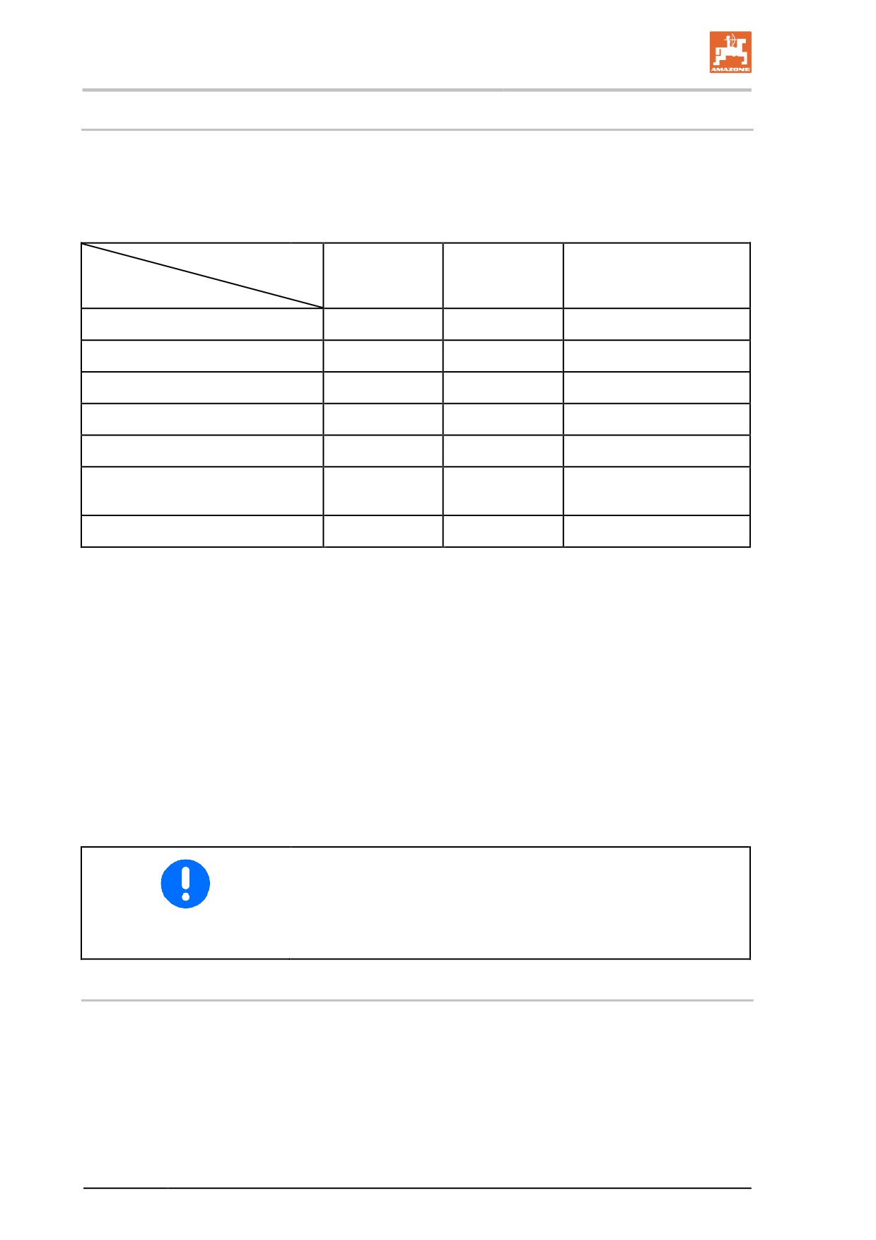
with/on the machine. The operator must clearly specify the responsi-
bilities of the people charged with operation and maintenance work.
People being trained may only work with/on the machine under the
supervision of an experienced person.
Person
Person special-
Trained opera-
Persons with specialist
ly trained for the
tor2)
training
Activity
activity1)
(specialist workshop*)3)
Loading/Transport
X
X
X
Commissioning
--
X
--
Set-up, tool installation
--
--
X
Operation
--
X
--
Maintenance
--
--
X
Troubleshooting and fault elimina-
X
--
X
tion
Disposal
X
--
--
Legend:
X..permitted
--..not permitted
1)
A person who can assume a specific task and who can carry out
this task for an appropriately qualified company.
2)
Instructed persons are those who have been instructed in their
assigned tasks and in the possible risks in the case of improper
behaviour, have been trained if necessary, and have been in-
formed about the necessary protective equipment and
measures.
3)
People with specialist technical training shall be considered as a
specialist. Due to their specialist training and their knowledge of
the appropriate regulations, they can evaluate the work with
which they have been charged and detect possible dangers.
Comment:
A qualification equivalent to specialist training can be obtained
from several years' experience in the relevant field.
If maintenance and repair work on the machine is additionally marked
"Workshop work", only a specialist workshop may carry out such
work. The personnel of a specialist workshop shall possess the ap-
propriate knowledge and suitable aids (tools, lifting and support
equipment) for carrying out the maintenance and repair work on the
machine in a way which is both appropriate and safe.
2.7
Safety measures in normal operation
Only operate the machine if all the safety and protection equipment is
fully functional.
Check the machine at least once a day for visible damage and check
the function of the safety and protection equipment.
16
General safety instructions
2.8
Danger from residual energy
Note that there may be residual mechanical, hydraulic, pneumatic and
electrical/electronic energy on the machine.
Use appropriate measures to inform the operating personnel. You can
find detailed information in the relevant sections of this operating
manual.
2.9
Maintenance and repair work, fault elimination
Carry out prescribed setting, maintenance and inspection work in
good time.
Secure all media such as compressed air and the hydraulic system
against unintentional start-up.
Carefully fix and secure larger assemblies to lifting gear when carry-
ing out replacement work.
Regularly check that bolted connections are firmly secured and tight-
en if necessary.
When the maintenance work is completed, check the function of the
safety devices
2.10
Design changes
You may make no changes, expansions or modifications to the ma-
chine without the authorisation of AMAZONEN-WERKE. This also
applies when welding support parts.
Any expansion or modification work shall require the written approval
of AMAZONEN-WERKE. Only use modification and accessory parts
approved by AMAZONEN-WERKE so that the type approval, for ex-
ample, remains valid in accordance with national and international
regulations.
Vehicles with an official type approval or with equipment connected to
a vehicle with a valid type approval or approval for road transport
according to the German road traffic regulations must be in the state
specified by the approval.
WARNING
Risk of crushing, cutting, being trapped or drawn in, or impact
through the failure of support parts.
It is strictly forbidden to
•
drill holes in the frame or on the running gear.
•
increase the size of existing holes on the frame or the running
gear.
•
weld support parts.
17
General safety instructions
2.10.1
Spare and wear parts and aids
Immediately replace any machine parts which are not in a perfect
state.
Only use genuine AMAZONE spare and wear parts, or those ap-
proved by AMAZONEN-WERKE, so that the type approval remains
valid according to the national and international regulations. The use
of spare and wear parts from third parties does not guarantee that
they have been constructed in a way as to meet the requirements
placed on them.
AMAZONEN-WERKE shall accept no liability for damage caused by
the use of non-approved spare and wear parts or aids.
2.11
Cleaning and disposal
Handle and dispose of any materials used carefully, in particular
•
when carrying out work on lubrication systems and equipment
and
•
when cleaning using solvents.
2.12
User workstation
The machine may only be operated by one person sitting in the driv-
er's seat of the tractor.
18
General safety instructions
2.13
Warning symbols and other signs on the machine
Always keep all the warning symbols on the machine clean and in a
legible state. Replace illegible warning symbols. You can obtain the
warning symbols from your dealer using the order number
(e.g. MD 078).
Warning symbols - structure
Warning symbols indicate danger areas on the machine and warn
against residual dangers. At these points, there are permanent or
unexpected dangers.
A warning symbol consists of two fields:
Field 1
is a symbol describing the danger, surrounded by triangular safety
symbol.
Field 2
is a symbol showing how to avoid the danger.
Warning symbols - explanation
The column Order number and explanation provides an explanation
of the neighbouring warning symbol. The description of the warning
symbols is always the same and specifies, in the following order:
1. A description of the danger.
For example: risk of cutting
2. The consequence of non-compliance with the risk avoidance
instructions.
For example: causes serious injuries to fingers or hands.
3. Risk avoidance instructions.
For example: only touch machine parts when they have come to
a complete standstill.
19
General safety instructions
2.13.1 Positions of warning symbols and other labels
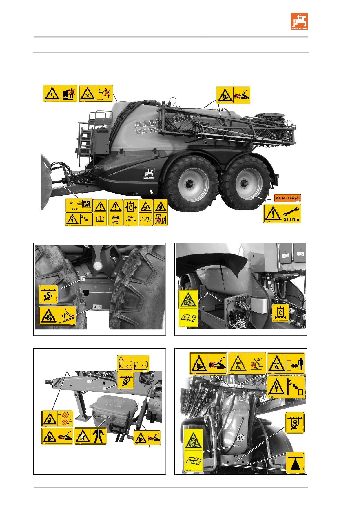
Warning symbols
The following diagrams show the arrangement of the warning symbols on the machine.
Fig. 1
Fig. 2
Fig. 3
Fig. 4
Fig. 5
20
General safety instructions
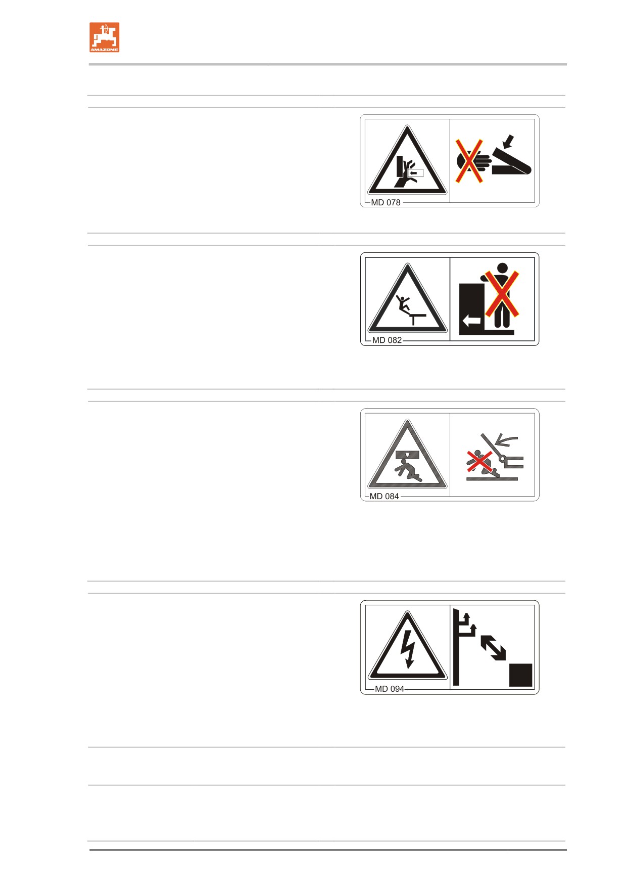
Order number and explanation
Warning symbols
MD 078
Risk of crushing fingers or hands by acces-
sible moving machine parts.
This danger causes serious injuries, including
loss of body parts such as fingers or hand.
Never reach into the danger area while the trac-
tor engine is running and the PTO shaft / hydrau-
lic system is connected.
MD 082
Danger of falling from treads and platforms
when riding on the machine.
This danger causes serious or potentially fatal
injuries anywhere on the body.
It is forbidden to ride on the machine and/or
climb the machine while it is running. This also
applies to machines with treads or platforms.
Make sure that nobody is riding on the machine.
MD 084
Risk of crushing the entire body due to
standing in the swivel range when machine
parts are being lowered.
This danger can cause extremely serious and
potentially fatal injuries.
•
It is forbidden to stand in the swivel range of
the machine when machine parts are being
lowered.
•
Instruct personnel to leave the swivel range
of any machine parts which can be lowered
before you lower the parts.
MD 094
Risk of electric shock or burns from accidentally
touching overhead power lines or by coming
within the prohibited distance of high voltage
overhead power lines.
This danger causes serious or potentially fatal
injuries anywhere on the body.
Maintain a sufficient distance from electrical
overhead cables when swinging any parts of the
machine in and out.
Nominal voltage
Safety distance from
transmission lines
up to 1 kV
1 m
over 1 up to 110 kV
2 m
over 110 up to 220 kV
3 m
over 220 up to 380 kV
4 m
21
General safety instructions
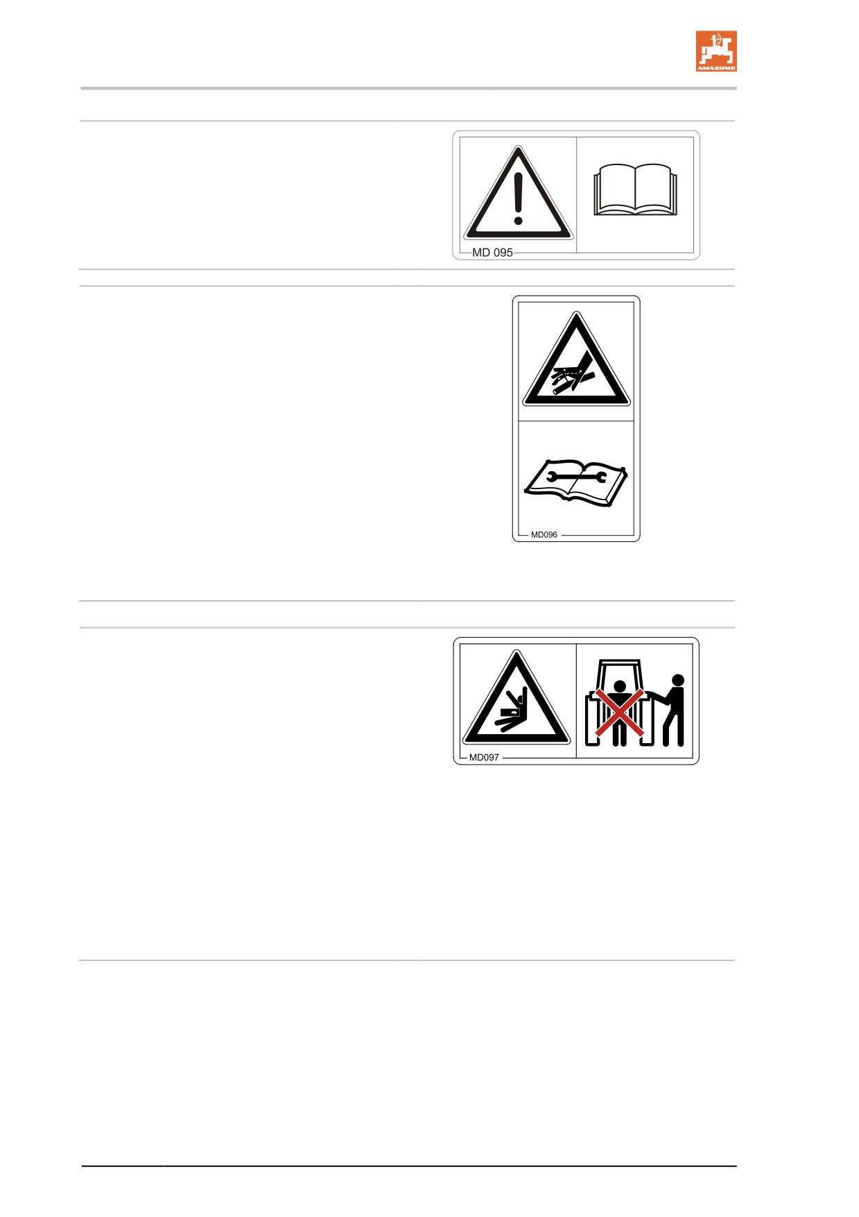
MD 095
Read and follow the operating manual and safety
information before starting up the machine!
MD 096
Danger from escaping high-pressure hydrau-
lic fluid due to leaking hydraulic hose lines.
This danger may cause serious injuries, perhaps
even resulting in death, if escaping high-pressure
hydraulic fluid passes through the skin and into
the body.
•
Never attempt to plug leaks in hydraulic
hose lines with your hand or fingers.
•
Read and observe the information in the
operating manual before carrying out
maintenance work on the hydraulic hose
lines.
•
If you are injured by hydraulic fluid, contact
a doctor immediately.
MD 097
Danger from crushing and impacts between
the rear of the tractor and the machine during
coupling/uncoupling.
These dangers can cause extremely serious and
potentially fatal injuries.
•
It is prohibited to operate the tractor's 3-
point hydraulic system while persons are
present between the rear of the tractor and
the machine.
•
Only actuate the operator controls for the
tractor's three-point hydraulic system
ο from the intended workstation beside
the tractor.
ο if you are outside of the danger area
between the tractor and the machine.
22
General safety instructions
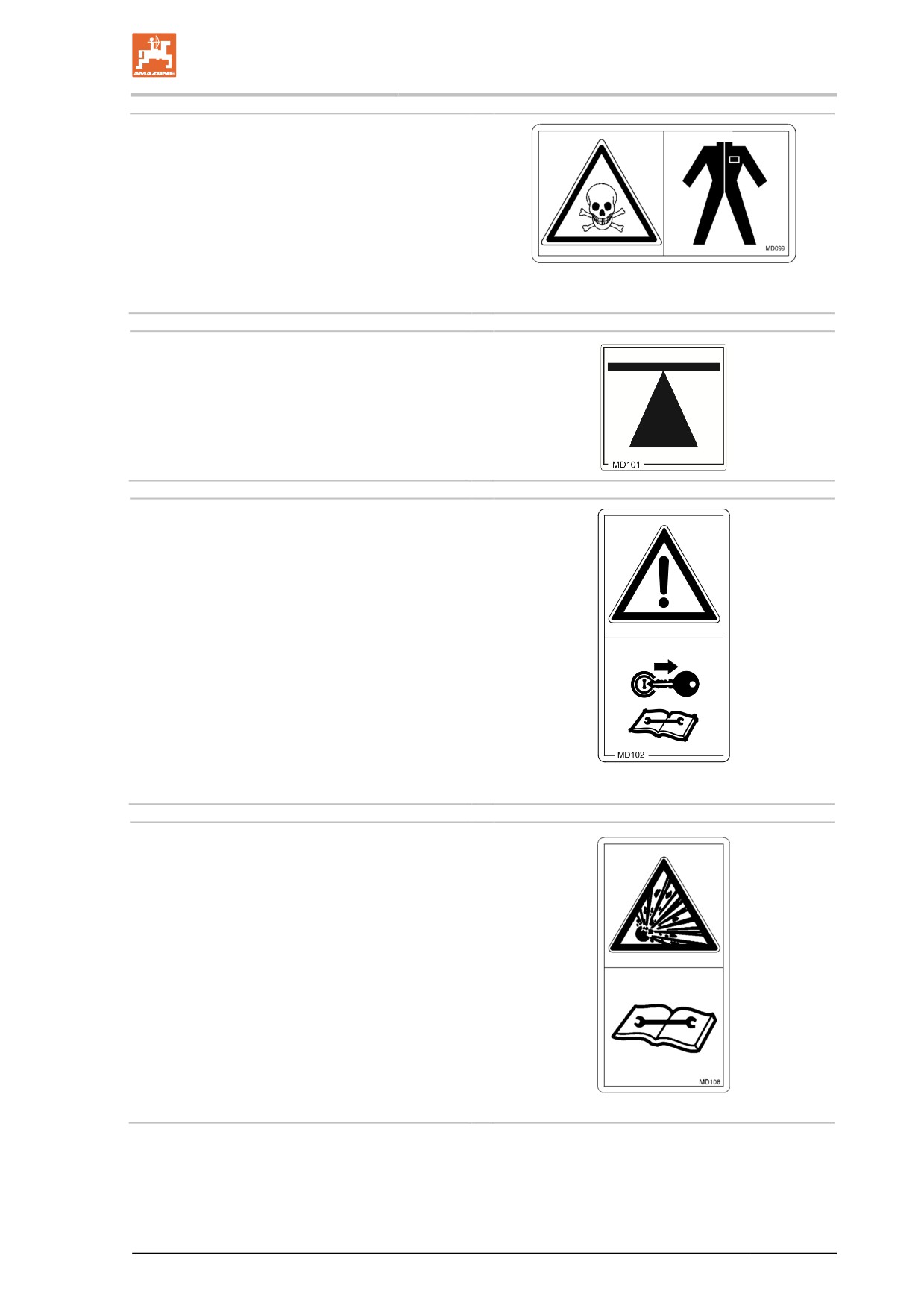
MD 099
Risk of contact with hazardous materials due
to improper handling.
This danger can cause extremely serious and
potentially fatal injuries.
Before coming into contact with hazardous mate-
rials, put on protective clothing. Follow the manu-
facturer's safety instructions for the materials to
be processed
MD101
This symbol indicates jacking points for lifting
gear (jack).
MD 102
Danger from intervention in the machine, e.g.
installation, adjusting, troubleshooting,
cleaning, maintaining and repairing, due to
the tractor and the machine being started
unintentionally and rolling.
These dangers can cause extremely serious and
potentially fatal injuries.
•
Secure the tractor and the machine against
unintentional start-up and rolling before any
intervention in the machine.
•
Depending on the type of intervention, read
and observe the instructions in the appro-
priate sections of the operating manual.
MD 108
Risk of explosion, or danger from hydraulic
fluid escaping under high pressure, caused
by the pressure accumulator which is under
pressure from gas and oil.
These dangers can cause serious and potentially
fatal injuries if highly pressurised, escaping hy-
draulic fluid penetrates the skin and passes into
the body.
•
Read and observe the instructions in the
operating manual before carrying out any
maintenance or repair work.
•
If you are injured by hydraulic fluid, contact
a doctor immediately.
23
General safety instructions
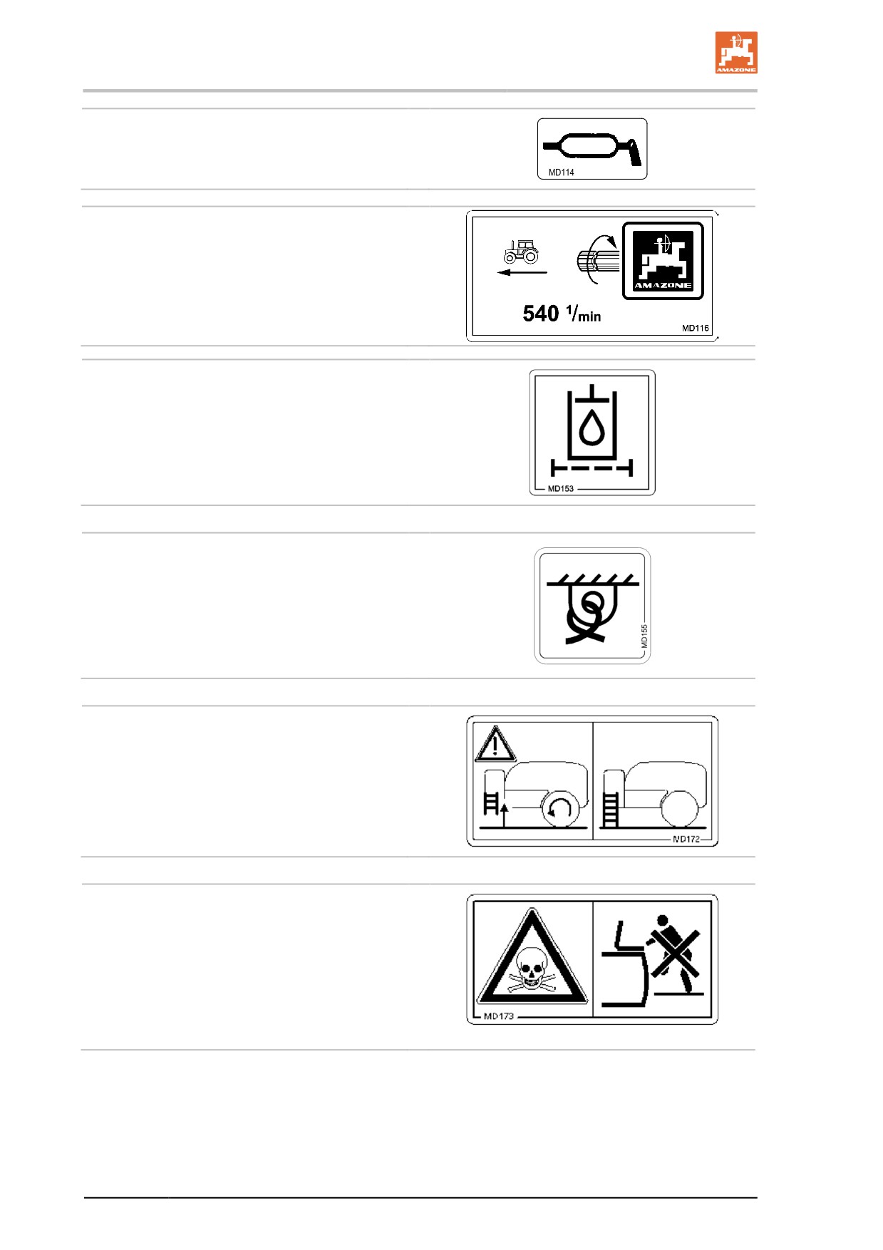
MD 114
This symbol indicates a lubrication point
MD 116
This symbol indicates the maximum drive speed
(540 rpm) and direction of rotation of the drive
shaft on the machine side.
MD 153
This pictogram indicates a hydraulic oil filter.
MD 155
This icon designates the restraint points for tieing
the machine to a transport vehicle allowing the
machine to be transported in a safe manner.
MD 172
Swing the ladder to the operation platform up-
wards into transport position when driving!
MD 173
Risk of breathing in hazardous materials via
poisonous vapours from the spray liquid
tank.
This danger can cause extremely serious and
potentially fatal injuries.
Never climb into the spray liquid tank.
24
General safety instructions
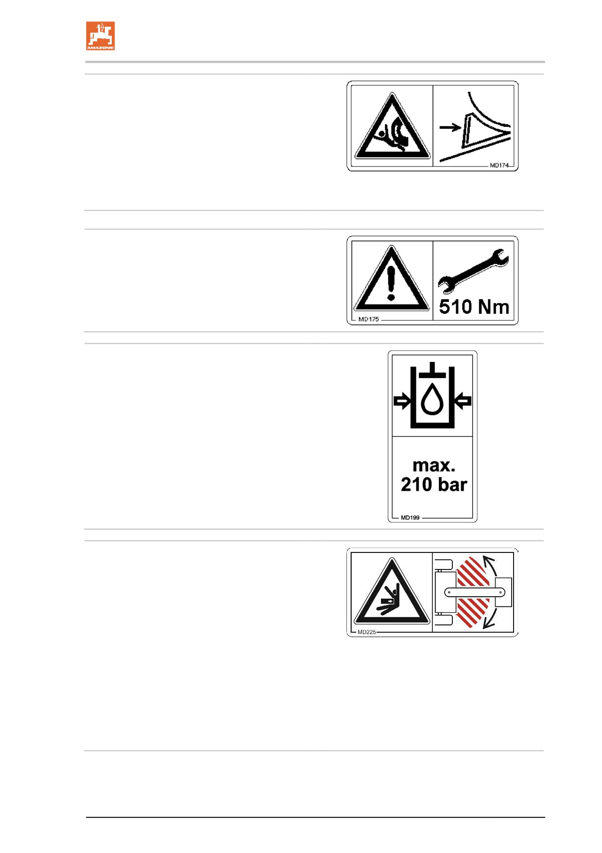
MD 174
Danger from unintended continued movement of
the machine.
Causes serious, potentially fatal injuries any-
where on the body.
Secure the machine against unintended contin-
ued movement before uncoupling the machine
from the tractor. To do this, use the parking
brake and/or the wheel chock(s).
MD 175
The torque of the screw connection is 510 Nm.
MD 199
The maximum operating pressure of the hydrau-
lic system is 210 bars.
MD 225
Danger of crushing the entire body, caused
by remaining in the swivel range of the draw-
bar between tractor and attached machine.
This danger can cause extremely serious and
potentially fatal injuries.
•
Do not remain in the danger area between
tractor and machine while the tractor engine
is running and the tractor is not secured
against unintentional rolling.
•
Instruct anyone in the danger area between
tractor and machine to leave the danger ar-
ea while the tractor engine is running and
the tractor is not secured against uninten-
tional rolling.
25
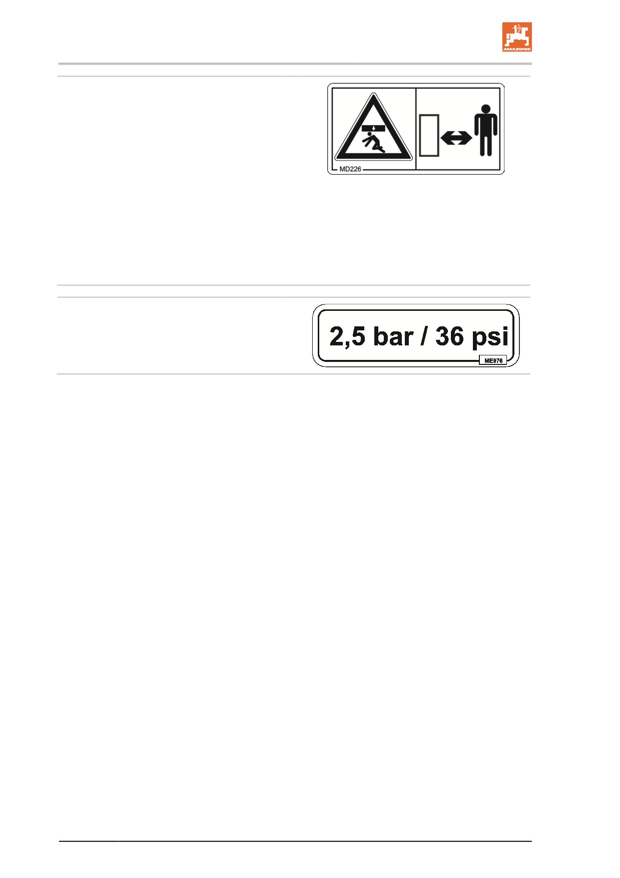
General safety instructions
MD 226
Risk of crushing the entire body due to
standing under suspended loads or raised
machine parts.
This danger can cause extremely serious and
potentially fatal injuries.
•
It is forbidden to stand under suspended
loads or raised machine parts.
•
Maintain an adequate safety distance from
any suspended loads or raised machine
parts.
•
Ensure that all personnel maintain an ade-
quate safety distance from suspended
loads or raised machine parts.
ME 976
The required tyre pressure is 2.5 bar.
26
General safety instructions
2.14
Potential risks from not observing the safety instructions
Non-compliance with the safety information
•
can pose both a danger to people and also to the environment
and machine.
•
can lead to the loss of all warranty claims.
In particular, non-compliance with the safety information could pose
the following risks:
•
Danger to people through non-secured working areas.
•
Failure of important machine functions.
•
Failure of prescribed methods of maintenance and repair.
•
Danger to people through mechanical and chemical influences.
•
Risk to the environment through leakage of hydraulic fluid.
2.15
Safety-conscious working
Besides the safety information in this operating manual, the generally
applicable national workplace safety and accident prevention regula-
tions are binding.
Comply with the accident prevention instructions on the warning sym-
bols.
When driving on public roads and routes, comply with the appropriate
statutory road traffic regulations.
27
General safety instructions
2.16
Safety information for users
WARNING
Risk of crushing, cutting, being trapped or drawn in, or impact
through inadequate roadworthiness and operational safety.
Before starting up the machine and the tractor, always check their
roadworthiness and operational safety.
2.16.1
General safety and accident prevention information
•
Beside these instructions, comply with the generally applicable
national safety and accident prevention regulations.
•
The warning symbols and other labels attached to the machine
provide important information on safe machine operation. Com-
pliance with this information is in the interests of your safety.
•
Before moving off and starting up the machine, check the imme-
diate area of the machine (children). Ensure that you can see
clearly.
•
It is forbidden to ride on the machine or use it as a means of
transport.
•
Drive in such a way that you always have full control over the tractor
with the attached machine.
In so doing, take your personal abilities into account, as well as
the road, traffic, visibility and weather conditions, the driving
characteristics of the tractor and the connected machine.
Coupling and uncoupling the machine
•
Only connect and transport the machine with tractors suitable for
the task.
•
When coupling machines to the tractor's three-point linkage, the
linkages of the tractor and the machine must always be the
same.
•
Connect the machine to the prescribed equipment in accordance
with the specifications.
•
When coupling machines to the front or the rear of the tractor,
the following may not be exceeded:
ο The approved total tractor weight
ο The approved tractor axle loads
ο The approved load capacities of the tractor tyres
•
Secure the tractor and the machine against rolling unintentionally
before coupling or uncoupling the machine.
•
Do not stand between the machine and tractor to be coupled
while the tractor is approaching the machine.
Any helpers may only act as guides standing next to the vehi-
cles, and may only move between the vehicles when both are at
a standstill.
•
Before connecting the machine to or disconnecting the machine
from the tractor's three-point linkage, secure the operating lever of
the tractor hydraulic system so that unintentional raising or lowering
is prevented.
28
General safety instructions
•
When coupling and uncoupling machines, move the support
equipment (if available) to the appropriate position (stability).
•
When actuating the support equipment, there is a risk of injury
from crushing and cutting points.
•
Be particularly careful when coupling the machine to the tractor
or uncoupling it from the tractor. There are crushing and cutting
points in the area of the coupling point between the tractor and
the machine.
•
It is forbidden to stand between the tractor and the machine
when actuating the three-point linkage.
•
Coupled supply lines
ο must give slightly to all movements while cornering without
tensioning, kinking or rubbing.
ο must not chafe against other parts.
•
The release ropes for quick couplings must hang loosely and
must not release themselves when lowered.
•
Also ensure that uncoupled machines are stable.
Use of the machine
•
Before starting work, ensure that you understand all the equip-
ment and actuation elements of the machine and their function.
There is no time for this when the machine is already in opera-
tion.
•
Do not wear loose-fitting clothing. Loose clothing increases the
risk of being caught by the drive shaft.
•
Only start-up the machine, when all the safety equipment has
been attached and is in the safety position.
•
Comply with the maximum load for the connected machine and
the permissible axle and drawbar loads for the tractor. If neces-
sary, drive only with a partially filled tank.
•
It is forbidden to stand in the working area of the machine.
•
It is forbidden to stand in the turning and swivel range of the
machine.
•
There are crushing and cutting points at externally-actuated (e.g.
hydraulic) machine points.
•
Only actuate externally-actuated machine parts when you are
sure that no-one is standing within the prescribed safety dis-
tance.
•
Before leaving the tractor, secure it against unintended starting
and rolling.
To do this:
ο lower the machine onto the ground
ο apply the parking brake
ο switch off the tractor engine
ο remove the ignition key
29
General safety instructions
Machine transportation
•
When using public highways, national road traffic regulations
must be observed.
•
Before moving off, check:
ο the correct connection of the supply lines
ο the lighting system for damage, function and cleanliness
ο the brake and hydraulic system for visible damage
ο that the parking brake is completely disengaged
ο the function of the brake system
•
Ensure that the tractor has sufficient steering and braking power.
Any machines and front/rear weights connected to the tractor
influence the driving behaviour and the steering and braking
power of the tractor.
•
If necessary, use front weights.
The front tractor axle must always be loaded with at least 20% of
the tractor empty weight, in order to ensure sufficient steering
power.
•
Always fix the front or rear weights to the intended fixing points
according to regulations.
•
Comply with the maximum load for the connected machine and
the approved axle and drawbar loads for the tractor.
•
The tractor must guarantee the prescribed brake delay for the
loaded vehicle combination (tractor plus connected machine).
•
Check the brake power before moving off.
•
When turning corners with the machine connected, take the
broad load and balance weight of the machine into account.
•
If the machine is fixed to the tractor's three-point linkage or lower
links, before moving off, ensure sufficient side locking of the trac-
tor lower links.
•
Before moving off, move all the swivellable machine parts to the
transport position.
•
Before moving off, secure all swivellable machine parts in the
transport position against dangerous position changes. Use the
transport safety catches intended for this.
•
Before transportation, secure the operating lever of the three-
point hydraulic system against unintentional raising or lowering
of the connected or coupled machine.
•
Check that the transport equipment, e.g. lighting, warning
equipment and protective equipment, is correctly mounted on the
machine.
•
Before transportation, carry out a visual check that the upper and
lower link pins are firmly fixed with the linchpin against uninten-
tional release.
•
Adjust your driving speed to the prevailing conditions.
•
Before driving downhill, switch to a low gear.
•
Before moving off, always switch off independent wheel braking
(lock the pedals).
30
General safety instructions
2.16.2
Hydraulic system
•
The hydraulic system is under a high pressure.
•
Ensure that the hydraulic hose lines are connected correctly.
•
When connecting the hydraulic hose lines, ensure that the hy-
draulic system is depressurised on both the machine and tractor
sides.
•
It is forbidden to lock the operator controls on the tractor used for
hydraulic and electrical movements of components, e.g. folding,
swivelling and pushing movements. The movement must stop
automatically when you release the appropriate control. This
does not apply to equipment movements that:
ο are continuous
ο are automatically controlled
ο require a floating position or pressed position to function
•
Before working on the hydraulic system,
ο lower the machine
ο depressurise the hydraulic system
ο shut off the tractor engine
ο apply the parking brake
ο remove the ignition key
•
Have the hydraulic hose lines checked at least once a year by a
specialist for proper functioning.
•
Replace the hydraulic hose lines if they are damaged or worn.
Only use AMAZONE original hydraulic hose lines.
•
The hydraulic hose lines should not be used for longer than six
years. This period includes any storage time of a maximum of
two years. Even with proper storage and approved use, hoses
and hose connections are subject to natural ageing, thus limiting
the length of use. However, it may be possible to specify the
length of use from experience values, in particular when taking
the risk potential into account. In the case of hoses and hose
connections made from thermoplastics, other guide values may
be decisive.
•
Never attempt to plug leaks in hydraulic hose lines with the hand
or fingers.
Escaping high pressure fluid (hydraulic fluid) may pass through
the skin and ingress into the body, causing serious injuries.
If you are injured by hydraulic fluid, contact a doctor immediately.
Danger of infection.
•
When searching for leakage points, use suitable aids, to avoid
the serious risk of infection.
31
General safety instructions
2.16.3
Electrical system
•
When working on the electrical system, always disconnect the
battery (negative terminal).
•
Only use the prescribed fuses. If fuses are used that are too
highly rated, the electrical system will be destroyed - risk of fire.
•
Ensure that the battery is connected correctly - firstly connect the
positive terminal and then connect the negative terminal. When
disconnecting the battery, disconnect the negative terminal first,
followed by the positive terminal.
•
Always place the appropriate cover over the positive battery
terminal. If there is accidental earth contact, there is a risk of ex-
plosion.
•
Risk of explosion. Avoid sparking and naked flames in the area
of the battery.
•
The machine may be equipped with electronic components
whose function is influenced by electromagnetic interference
from other units. Such interference can pose risks to people, if
the following safety information is not followed.
ο If retrofitting electrical units and/or components on the ma-
chine with a connection to the on-board power supply, the
user is responsible for checking whether the installation
might cause faults on the vehicle electronics or other com-
ponents.
ο Ensure that the retrofitted electrical and electronic compo-
nents comply with the EMC directive 2014/30/EU in the ap-
propriate version and bear the CE mark.
32
General safety instructions
2.16.4
Universal joint shaft operation
•
Use only the PTO shafts prescribed by the AMAZONEN-WERKE
factories, equipped with the proper safety devices.
•
Also read and follow the operating manual from the PTO shaft
manufacturer.
•
The protective tube and PTO shaft guard must be undamaged,
and the shield of the tractor and machine universal joint shaft
must be attached and be in proper working condition.
•
Work is prohibited while the safety devices are damaged.
•
You may install or remove the PTO shaft only after you have
done all of the following:
ο Switched off the universal joint shaft
ο Switched off the tractor engine
ο Applied the parking brake
ο the ignition key has been removed
•
Always ensure that the PTO shaft is installed and secured cor-
rectly.
•
When using wide-angle PTO shafts, always install the wide an-
gle joint at the pivot point between the tractor and machine.
•
Secure the PTO shaft guard by attaching the chain(s) to prevent
movement.
•
Observe the prescribed pipe overlaps in transport and opera-
tional positions. (Read and follow the operating manual from the
PTO shaft manufacturer.)
•
When turning corners, observe the permitted bending and dis-
placement of the PTO shaft.
•
Before switching on the universal joint shaft, check that the se-
lected universal joint shaft speed of the tractor matches the per-
mitted drive speed of the machine.
•
Instruct people to leave the danger area of the machine before
you switch on the universal joint shaft.
•
While work is being carried out with the universal joint shaft,
there must be no one in the area of the universal joint or PTO
shaft while it is turning.
•
Never switch on the universal joint shaft while the tractor engine
is shut off.
•
Always switch off the universal joint shaft whenever excessive
bending occurs or it is not needed.
•
WARNING! After the universal joint shaft is switched off, there is
a danger of injury from the continued rotation of freewheeling
machine parts.
Do not approach the machine too closely during this time. You
may work on the machine only after all machine parts have
come to a complete stop.
•
Secure the tractor and machine against unintentional starting
and unintentional rolling before you perform any cleaning, servic-
ing or maintenance work on universal joint shaft-driven machines
or PTO shafts.
•
After decoupling the PTO shaft, place it on the holder provided.
33
General safety instructions
•
After removing the PTO shaft, attach the protective sleeve to the
universal joint shaft stub.
•
When using the travel-dependent universal joint shaft, note that
the universal joint shaft speed depends on the drive speed, and
that the direction of rotation reverses when you drive in reverse.
2.16.5
Coupled machines
•
Observe the permitted combination options of the attachment
equipment on the tractor and the machine drawbar.
Only couple permitted combinations of vehicles (tractor and at-
tached machine).
•
On single axle machines, observe the maximum permitted draw-
bar load of the tractor on the attachment equipment.
•
Ensure that the tractor has sufficient steering and braking power.
Machines attached or coupled to a tractor influence the driving
behaviour and steering and braking power of the tractor, and in
particular single axle machines with drawbar loads on the tractor.
•
Only one specialist workshop can adjust the height of the draw-
bar if it is a straight drawbar with drawbar load.
2.16.6
Brake system
•
Only specialist workshops or recognised brake services can
carry out adjustment and repair work on the brake system.
•
Have the brake system thoroughly checked regularly.
•
If there are any malfunctions, stop the tractor immediately using
the brake system. Have the malfunction rectified immediately.
•
Before performing any work on the braking system, park the
machine safely and secure the machine against unintentional
lowering or rolling away (wheel chocks).
•
Be particularly careful when carrying out any welding, torch cut-
ting or drilling work in the area of the brake lines.
•
Always carry out a braking test after any adjusting or repair work
on the braking system.
34
General safety instructions
Pneumatic braking system
•
Before coupling the machine, clean the sealing rings on the hose
couplings of the supply and brake line.
•
Only move off with the machine connected when the pressure
gauge on the tractor shows 5.0 bar.
•
Drain the air reservoir every day.
•
Before driving without the machine, lock the hose couplings on
the tractor.
•
Hang the hose couplings of the machine supply and brake lines
in the appropriate empty couplings.
•
When filling up or replacing the brake fluid, use the prescribed
fluid. When replacing the brake fluid, comply with the appropriate
regulations.
•
Do not make any changes to the specified settings on the brake
valves.
•
Replace the air reservoir if:
ο the air reservoir can be moved in the tensioning belts
ο the air reservoir is damaged
ο the rating plate on the air reservoir is rusty, loose or miss-
ing.
Hydraulic brake system for export machines
•
Hydraulic brake systems are prohibited in Germany.
•
When filling up or replacing the brake fluid, use the prescribed
hydraulic fluids. When replacing the hydraulic fluids, comply with
the appropriate regulations.
2.16.7 Tyres
•
Repair work on tyres and wheels may only be carried out by
specialists with suitable installation tools.
•
Check the air pressure at regular intervals.
•
Inflate tyres to the specified pressure. If the air pressure in the
tyres is too high, then there is a risk of explosions.
•
Park the machine in a safe place and lock the machine against
unintentional lowering and rolling (parking brake, wheel chocks),
before carrying out work on the tyres.
•
Tighten or retighten all the fixing screws and nuts in accordance
with the specifications of AMAZONEN-WERKE.
35
General safety instructions
2.16.8 Field sprayer operation
•
Observe the recommendations of the crop protection agent
manufacturer in respect of
ο protective clothing
ο warning information on exposure to crop protection agents
ο regulations on dosing, applications and cleaning
•
When handling crop protection products, observe the safety
instructions provided by the crop protection product manufactur-
er.
•
Using unauthorised crop protection products is prohibited!
•
Never open lines which are under pressure.
•
The nominal volume of the spray liquid tank must not be ex-
ceeded during filling.
•
When there will be exposure to crop protection agent, wear the
proper protective clothing, i.e. gloves, overalls, safety glasses,
etc.
•
When using tractors with a cab with ventilation fans, replace the
fresh air filters with activated carbon filters.
•
Observe the information on the compatibility of crop protection
agents and substances for the field sprayer.
•
Do not spray any crop protection agents which have a tendency
to stick together or set.
•
Do not fill field sprayers with water from bodies of water which
are open to the public, for the protection of people, animals and
the environment.
•
Only fill field sprayers
ο using a free flow from the mains water supply.
ο using genuine AMAZONE filling equipment.
36
General safety instructions
2.16.9
Cleaning, maintenance and repairs
•
Due to toxic vapours in the spray liquid tank, climbing into the
spray liquid tank is always forbidden.
•
Repair work in the spray liquid tank must only be carried out by a
specialist workshop!
•
As a general rule, only carry out maintenance or repair work or
cleaning when
ο the drive is switched off
ο the tractor engine has come to a complete stop
ο the ignition key has been removed
ο the machine connector has been removed from the on-
board computer
•
Regularly check the nuts and bolts for firm seating and retighten
them as necessary.
•
Secure the raised machine and/or raised machine parts against
unintentional lowering before performing any cleaning, mainte-
nance or repair work on the machine.
•
When replacing work tools with blades, use suitable tools and
gloves.
•
Dispose of oils, greases and filters in the appropriate way.
•
Disconnect the cable to the tractor generator and battery before
carrying out electrical welding work on the tractor and on at-
tached machines.
•
Only use genuine AMAZONE replacement hoses which stand up
to chemical, mechanical and thermal requirements. Only use
hose clamps made from V2A for installation.
•
Spare parts must meet at least the specified technical require-
ments of AMAZONEN-WERKE.This is ensured through the use
of genuine AMAZONE spare parts.
•
When repairing field sprayers which have been used for liquid
fertiliser application with ammonium nitrate / urea solution, ob-
serve the following points:
Residues of ammonium nitrate / urea solutions may form salts by
the evaporation of the water on or in the spray liquid tank. This
produces pure ammonium nitrate and urea. In its undiluted form,
ammonium nitrate is explosive when combined with organic sub-
stances, e.g. urea, and subjected to critical temperatures during
repair work (e.g. welding, grinding, filing).
This danger can be eliminated by thoroughly washing out the
spray liquid tank or the parts intended for repair with water, be-
cause the salt of the ammonium nitrate / urea solution is water-
soluble. For this reason, clean the field sprayer thoroughly with
water before carrying out repair work.
37
Loading and unloading
3
Loading and unloading
Loading and unloading with a tractor
WARNING
There is a risk of accident if the tractor is unsuitable and the
machine brake system is not connected to the tractor or filled.
•
Couple the machine to the tractor correctly before loading the
machine onto a transport vehicle or unloading it from a transport
vehicle.
•
You may only couple and transport the machine with a tractor for
loading and unloading, if the tractor meets the necessary power
requirements.
Pneumatic braking system:
•
Only move off with the machine connected when the pressure
gauge on the tractor shows 5.0 bar.
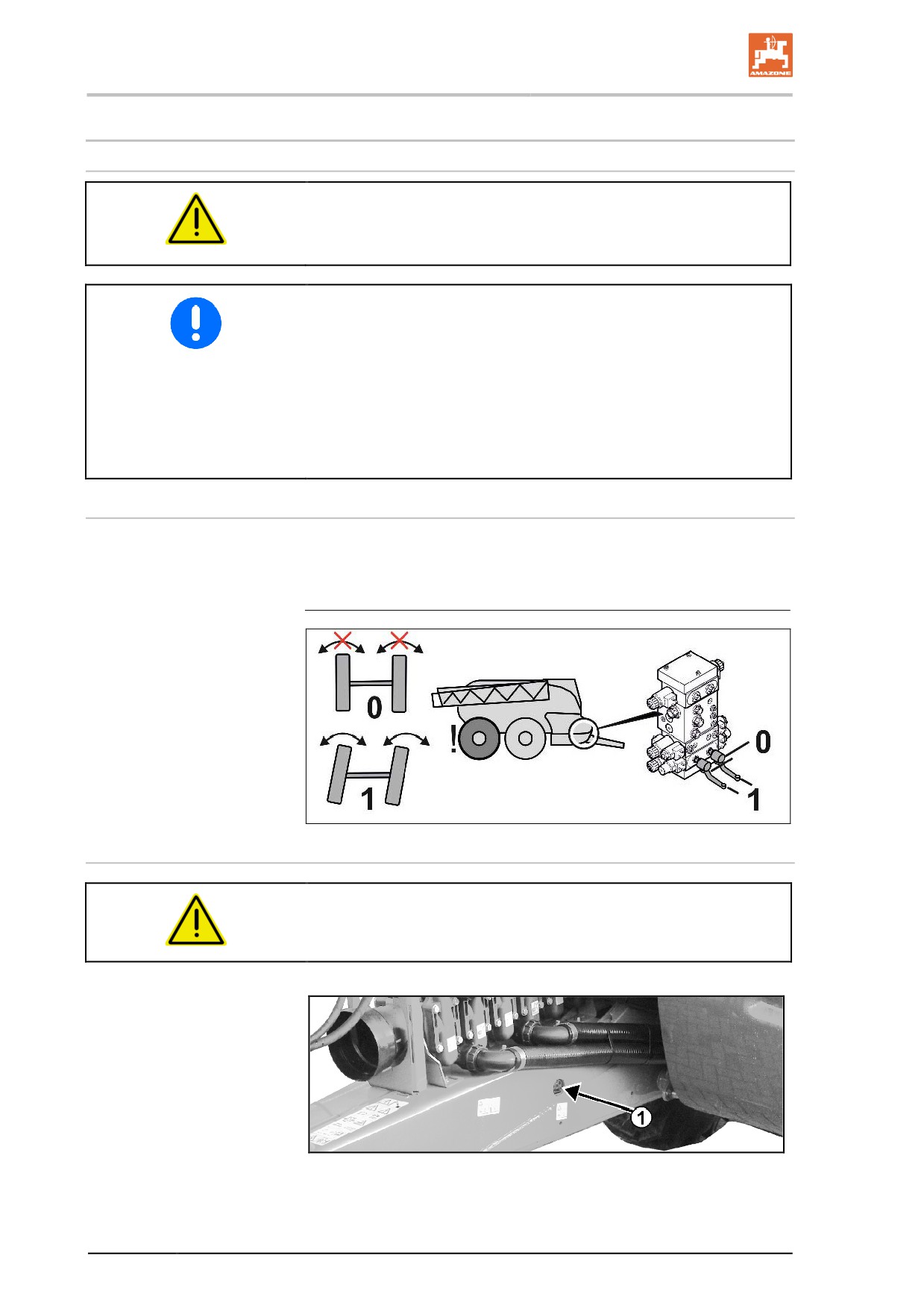
Locking the rear axle
Before the implement can be pushed in reverse onto an HGV, the
rear axle must be locked in the straight position (position 0).
After loading, unlock the axle (position 1).
Lashing points
DANGER
The 5 lashing points marked must be used for securing the ma-
chine on a transport vehicle.
•
Two lashing points to the left and right of the draw bar (Fig. 6/1).
Fig. 6
38
Loading and unloading
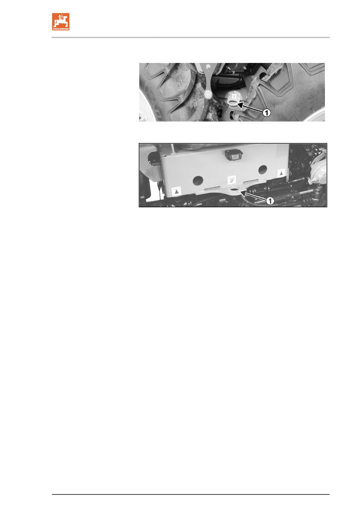
•
Lashing points on the right and left between the wheels (Fig.
7/1).
Fig. 7
•
One lashing point at the rear (Fig. 8/1).
Fig. 8
39

Product description
4
Product description
4.1
Overview of the assemblies
Fig. 9
(1) Spray liquid tank
(2) Filling opening for spray liquid tank
(3) Control terminal and induction bowl behind the swivel-mounted
cover.
(4) Flushing water tank 1
(5) Spraying - and agitator pumps
(6) Fresh water tank
(7) Maintenance platform with ladder
(8) Drawbar
(9) Hose cabinet
(10) Wheels and tyres
40
Product description
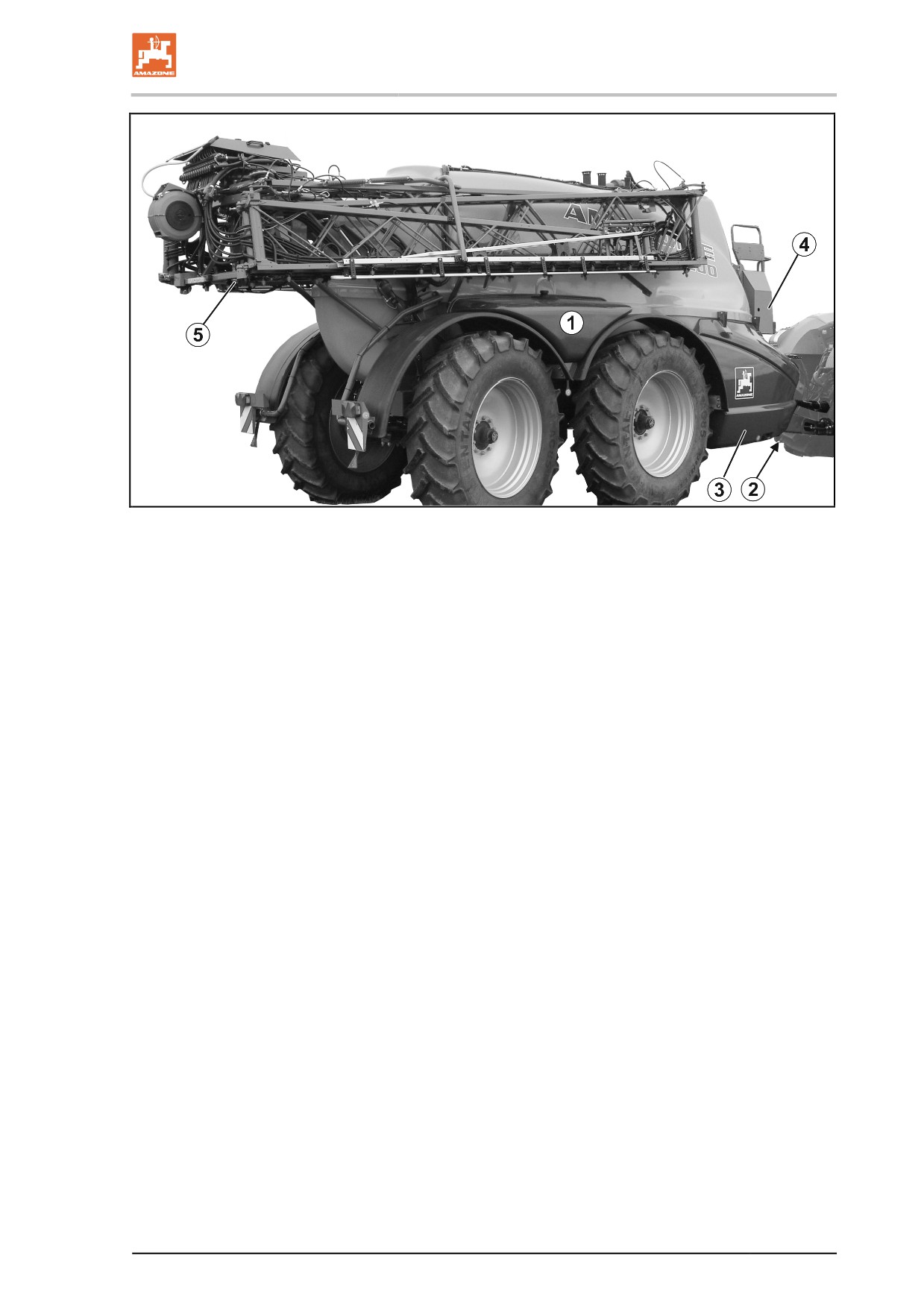
Fig. 10
(1) Flushing water tank 2
(2) Hydraulic stand
(3) Parking brake, Hydraulic block and and transport box behind the
swivel-mounted cover.
(4) Job- computer
(5) Super-L -boom
41
Product description
4.2
Safety and protection equipment
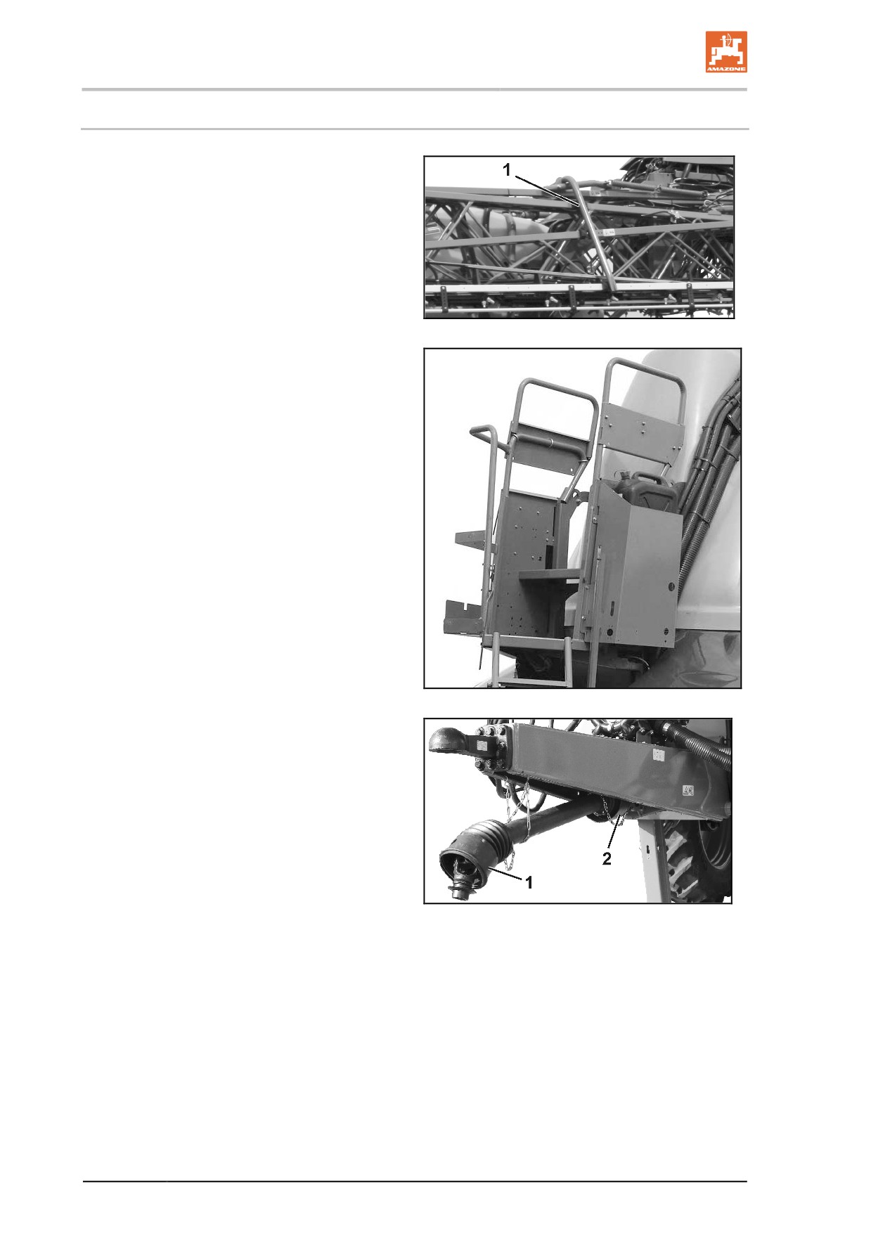
•
Transport locking mechanism (Fig. 11/1) to
prevent the Super-L boom from folding out
unintentionally
Fig. 11
•
Fig. 12:
Handrail on the Maintenance platform
Fig. 12
•
Fig. 13/…
(1) PTO shaft guard with supporting chains
(2) Machine PTO shaft guard
Fig. 13
42
Product description
4.3
Liquid circuit
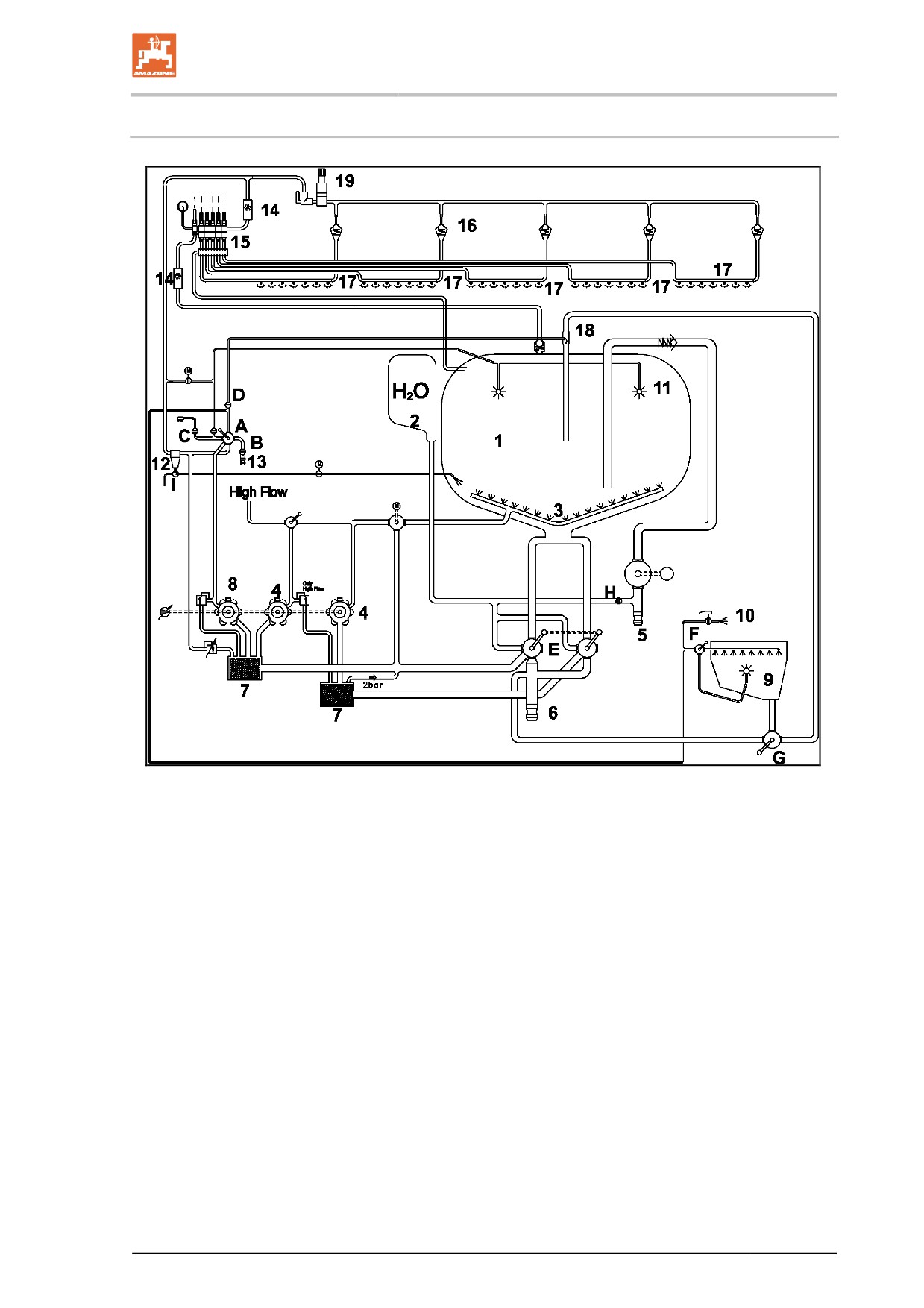
Fig. 14
1. Spray liquid tank
12. Pressure filter
(A) Pressure equipment 4-way
switch tap
2. Flushing water tank
13. Quick emptying via pump
(B) Quick emptying switch tap
3. Agitator
14. Flow rate
(C) External cleaning switch tap
4. Agitator pump
15. Part width section valve
(D) Injector switch tap
5. Filling connection - pressure
16. DUS - pressure circulating
filling
system
(E) Ring line / canister cleaning
switch tap
6. Filling connection - suction
17. Spray lines
hose
(F) Evacuate induction bowl /
18. Injector
Add injector.
7. Suction filter
19. Operating terminal
(G) Suction port, electrically actu-
8. Spraying pump
ated
20. DUS switch tap
9. Induction device
(H) Stop tap, flush water filling
(I) Switch tap - subsidiary agi-
10. Induction device cleaning
tator / pressure filter for
hose
draining
11. Cleaning nozzles
43
Product description
4.4
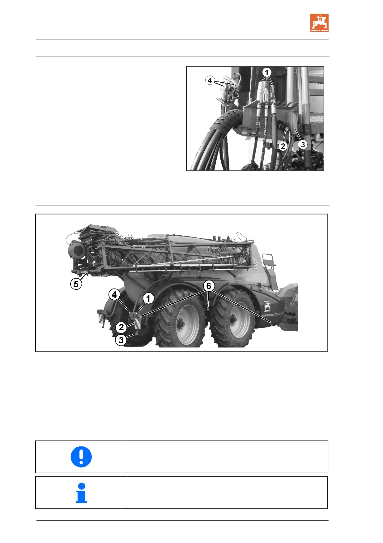
Supply hoses between the tractor and the machine
Supply hoses in parking position:
Fig. 15/...
(1) Hydraulic hose lines (depending on equip-
ment)
(2) Electric cable for lighting
(3) Machine cable with machine connector for
operating terminal
(4) Brake line with coupling head for air brake
(not shown)
Brake line with connection to hydraulic
brake
Fig. 15
4.5
Transportation equipment
Fig. 16
(1) Rear lights, brake lights, turn indicators
(2)
2 warning signs (square)
(3)
2 red reflectors (triangular)
(4)
1 registration plate holder with lighting
(5) Additional brake light and position light
(6)
2 x 3 reflectors, yellow
(lateral view: distance of max. 3m)
Connect the lighting system via the connector to the 7-pin tractor
socket.
For France, additional lateral danger signs and warning beacon on
the sprayer boom are required.
44
Product description
4.6
Intended use
The field sprayer
•
is intended for the transportation and application of crop protection
agents (insecticides, fungicides, herbicides, etc.) in the form of sus-
pensions, emulsions and mixtures, as well as of liquid fertilisers.
•
uses state-of-the-art technology to ensure organic success, pro-
vided that all the correct adjustments are made and correct dos-
es applied. Economical use of spraying agents and low rates of
pollution are achieved.
•
is intended exclusively for agricultural use, for treating field crops
Using the steering drawbar with AutoTrail control for precise tracking
is prohibited if on sloping terrain. See page 72.
Restrictions for use on slopes
(1) Driving on slopes with a full spray liquid tank
(2) Driving on slopes with a partially full spray liquid tank
(3) Application of residual quantities
(4) Turning
(5) Folding the sprayer boom
(1)
(2)
(3)
(4)
(5)
Along the contours
15%
15%
15%
15%
20%
Up/down the slope
15%
30%
15%
15%
20%
"Intended use" also covers:
•
Compliance with all the instructions in this operating manual.
•
Execution of inspection and maintenance work.
•
Exclusive use of genuine AMAZONE spare parts.
Other uses to those specified above are forbidden and shall be con-
sidered as improper.
For any damage resulting from improper use:
•
the operator bears the sole responsibility,
•
AMAZONEN-WERKE accepts no liability.
45

Product description
4.7
Regular device inspections
The implement underlies the European Union
universally applicable regular device inspections
(Crop Protection Directive 2009/128/EC and EN
ISO 16122).
Have the device inspected at regular intervals by
a recognised and certified inspection workshop.
The date for performing the next device inspec-
tion is written on the inspection plate on the im-
plement.
Fig. 17
4.8
Consequences of using certain crop protection agents
We would like to draw attention to the fact that extended exposure (20
hours) to crop protection agents with which we are familiar, e.g. Las-
so, Betanal and Tramat, Stomp, Iloxan, Mudecan, Elancolan and Ter-
idox, can cause damage to the pump diaphragms, hoses, spray lines
and tanks. The examples given are in no way intended to represent a
comprehensive list.
In particular, we warn against unauthorised mixtures of two or more
different crop protection agents.
Substances which have a tendency to stick together or set must not
be applied.
When using such aggressive crop protection agents, it is recom-
mended that the spray liquid be applied immediately after preparation
and then that the sprayer be thoroughly cleaned with water.
Viton membranes are available as replacements for pumps. These
are resistant to solvent-containing crop protection agents. However
their service life is reduced by use at low temperatures (e.g. AUS in
frosty conditions).
The materials and components used for AMAZONE field sprayers are
safe for liquid fertiliser.
46
Product description
4.9
Danger areas and danger points
The danger area is the area around the machine in which people can
be caught by:
•
work movements made by the machine and its tools
•
materials or foreign bodies thrown out of the machine
•
tools rising or falling unintentionally
•
unintentional rolling of the tractor and the machine
Within the machine danger area, there are danger points with perma-
nent or unexpected risks. Warning symbols indicate these danger
points and warn against residual dangers, which cannot be eliminated
for practical reasons. In such cases, the special safety regulations in
the appropriate section are valid.
No-one may stand in the machine danger area:
•
if the tractor engine is running with the PTO shaft / hydraulic
system connected.
•
if the tractor and machine are not protected against unintentional
start-up and rolling.
The operating person may only move the machine or switch or drive
the tools from the transport position to the working position or vice-
versa when there is no-one in the machine danger area.
Danger points exist:
•
between the tractor and field sprayer, particularly when coupling
and uncoupling.
•
where there are moving components.
•
on the moving machine.
•
in the swivel range of the sprayer boom.
•
in the spray liquid tank due to poisonous vapours.
•
under raised, unsecured machines or machine parts.
•
when unfolding/folding the sprayer boom in the vicinity of over-
head electricity cables, through contact with the cables.
47

Product description
4.10
Rating plate and CE mark
The rating plate shows:
•
Machine ID no.:
•
Type
•
Basic weight (kg)
•
Permissible axle load front / draw bar load
(kg)
•
Permissible axle load - axle 1 rear
•
Permissible axle load - axle 2 rear
•
Permissible total weight (kg)
•
Permissible system pressure (bar)
•
Factory
Fig. 18
•
Model year
4.11
Conformity
Directives/Standards designation
The implement complies
•
Implement directive
2006/42/EC
with the
•
EMC directive
2014/30/EU
48
Product description
4.12
Maximum permissible application rate
The permissible application rate of the implement is limited by:
•
the legally required agitator capacity.
The permissible application rate is of particular importance for
materials that require a high agitating intensity.
•
the technical maximum application rate of 200 l/min (without
HighFlow).
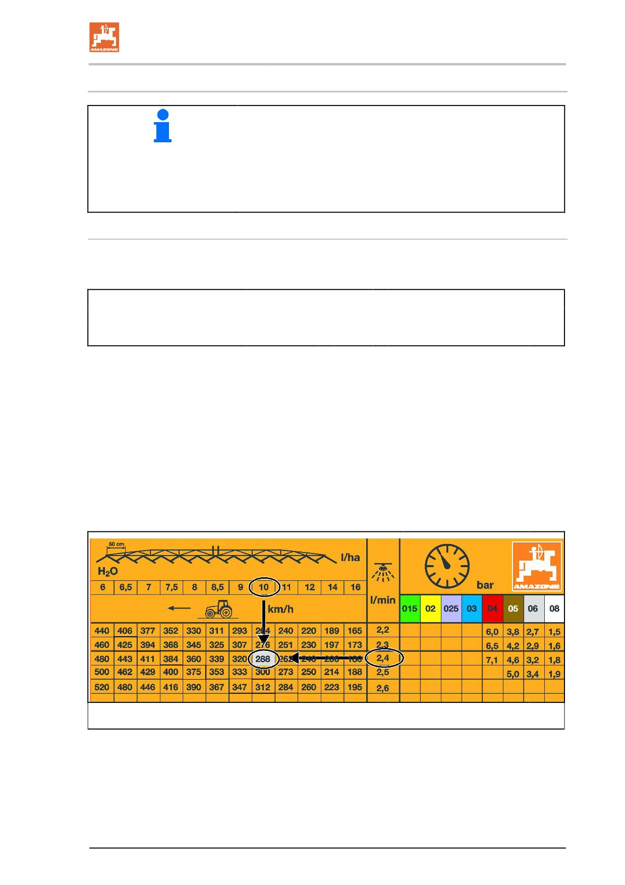
Determining the permissible application rate depending on the agitator capacity
Calculation formula for the application rate in l/min:
(The agitator capacity per minute must be 5% of the hopper volume)
Permissible application rate
=
Pump capacity
-
0.05 x nominal tank volume
[l/min]
[l/min]
[l]
(See page 52)
(See page 50)
Conversion of the application rate in l/ha:
1. Determine the application rate per nozzle (divide the permissible
application rate by the number of nozzles).
2. Read the application rate per hectare depending on the speed
from the spray table (See page 231).
Example:
UX 11200, Pump P 750, Super L 36 m, 72 nozzles, 10 km/h
Permissible application rate
=
735 l/min - 0,05 x 11200 l
= 175 l/min
→ Application rate per nozzle = 2.4 l/min
→ Permissible application rate per hectare
= 288 l/ha
49
Product description
4.13
Technical Data
4.13.1 asic implement
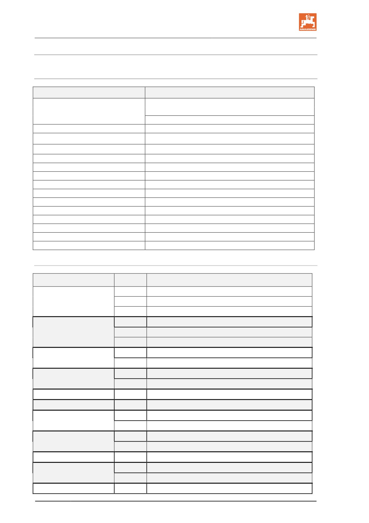
Typ
UX 11200
Spray liquid tank
Actual volume
12000 l
Nominal volume
11200 l
Flushing water tank
900 l
Filling height of maintenance platform
1180 mm
Permissible system pressure
10 bar
Working speed
4 - 18 km/h
Working width
24 - 40 m
Transport width
2,85 m
Central switching mechanism
Electric, part width section valve coupling
Spray pressure adjustment
Electric
Spray pressure setting range
0,8 - 10 bar
Spray pressure display
digital spray pressure display
Pressure filter
50 (80,100) mesh
Agitator
Infinitely adjustable
Spray rate control
Ground speed related, via job computer
Nozzle height
500 - 2500 mm
Part-width sections depending on the working width
Working width
Number
Number of nozzles per part width sections
5
8-9-8-9-8
21 m
7
6-6-7-4-7-6-6
9
6-4-5-4-4-4-5-4-6
5
9-10-10-10-9
24 m
7
6-6-8-8-8-6-6
9
6-5-5-5-6-5-5-5-6
7
8-7-8-8-8-7-8
27 m
9
6-6-6-6-6-6-6-6-6
7
9-7-8-8-8-7-9
28 m
9
7-6-6-6-6-6-6-6-7
30 m
9
8-7-6-6-6-6-6-7-8
32 m
9
8-6-7-7-8-7-7-6-8
9
7-8-7-7-8-7-7-8-7
33 m
11
6-6-6-6-6-6-6-6-6-6-6
7
10-10-10-12-10-10-10
36 m
9
9-9-7-7-8-7-7-9-9
36 m / 24 m
9
6-7-(9+1)-9-10-9-(9+1)-7-6
9
7-9-9-9-10-9-9-9-7
39 m
13
6-6-6-6-6-6-6-6-6-6-6-6-6
40 m
9
8-9-9-9-10-9-9-9-8
50
Product description
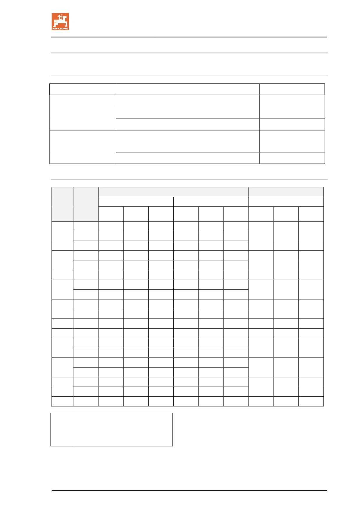
4.13.2 Residual amounts
Technical residue incl. pump
On the flat
23 l
Along the contours
•
Direction of travel 15 % to left
23 l
•
Direction of travel 15 % to righ
23 l
Along the gradient
•
15 % up the slope
37 l
•
15% down the slope
30 l
Technical boom residues
Number
Part-width section control
single nozzle control
Work-
of part-
Without DUS
With DUS
Without DUS
ing
width
width
sec-
A
B
C
A
B
C
A
B
C
tions
5
4,5 l
9,0 l
13,5 l
14,5 l
1,0 l
15,5 l
21 m
7
5,0 l
10,5 l
15,5 l
17,0 l
1,0 l
18,0 l
18,1 l
1,5 l
19,6 l
9
5,5 l
16,0 l
21,5 l
23,0 l
1,5 l
24,5 l
5
5,0 l
10,0 l
15,0 l
16,0 l
1,5 l
17,5 l
24 m
7
5,0 l
11,5 l
16,5 l
17,5 l
1,5 l
19,0 l
19,0 l
2,0 l
21,0 l
9
5,5 l
17,0 l
22,5 l
23,5 l
2,0 l
25,5 l
7
5,0 l
12,5 l
17,5 l
18,5 l
2,0 l
20,5 l
27 m
22,4 l
2,0 l
24,4 l
9
5,5 l
17,5 l
23,0 l
24,0 l
2,0 l
26,0 l
7
5,0 l
13,0 l
18,0 l
19,0 l
2,0 l
21,0 l
28 m
22,8 l
2,0 l
24,8 l
9
5,5 l
17,5 l
23,0 l
24,0 l
2,0 l
26,0 l
30 m
9
5,5 l
18,0 l
23,5 l
24,0 l
2,5 l
26,5 l
24,6 l
2,5 l
27,1 l
32 m
9
5,5 l
18,5 l
24,0 l
24,0 l
2,5 l
27,0 l
27,9 l
2,5 l
30,4 l
9
5,5 l
19,0 l
24,5 l
25,0 l
2,5 l
27,5 l
33 m
27,6 l
2,5 l
30,1 l
11
6,0 l
23,0 l
29,0 l
29,5 l
2,5 l
32,0 l
7
5,0 l
16,0 l
21,0 l
21,5 l
3,0 l
24,5 l
36 m
29,3 l
3,0 l
32,3 l
9
5,5 l
19,5 l
25,0 l
25,5 l
3,0 l
28,5 l
9
5,5 l
20,5 l
26,0 l
26,5 l
3,0 l
29,5 l
39 m
33,7 l
3,0 l
36,7 l
13
6,5 l
28,0 l
34,5 l
35,0 l
3,0 l
38,0 l
40 m
9
5,5 l
21,0 l
26,5 l
27,0 l
3,0 l
30,0 l
34,0 l
3,0 l
37,0 l
DUS:
Pressure circulating system
A:
Dilutable
B:
Not dilutable
C: Total
51

Product description
Technical data: pump equipment
Pump equipment
P 750
at 0 bar
Delivery capacity at nominal
750
speed
[l/min]
at 10 bar
735
Power requirement
[kW]
18,8
Construction type
12- cylinder
piston diaphragm pump
Pulsation damping
Pressure reservoir
The pumps are driven
•
directly by the PTO shaft.
→ Drive speed 540 rpm
•
directly from a hydraulic motor.
→ Drive speed 540 rpm
52
Product description
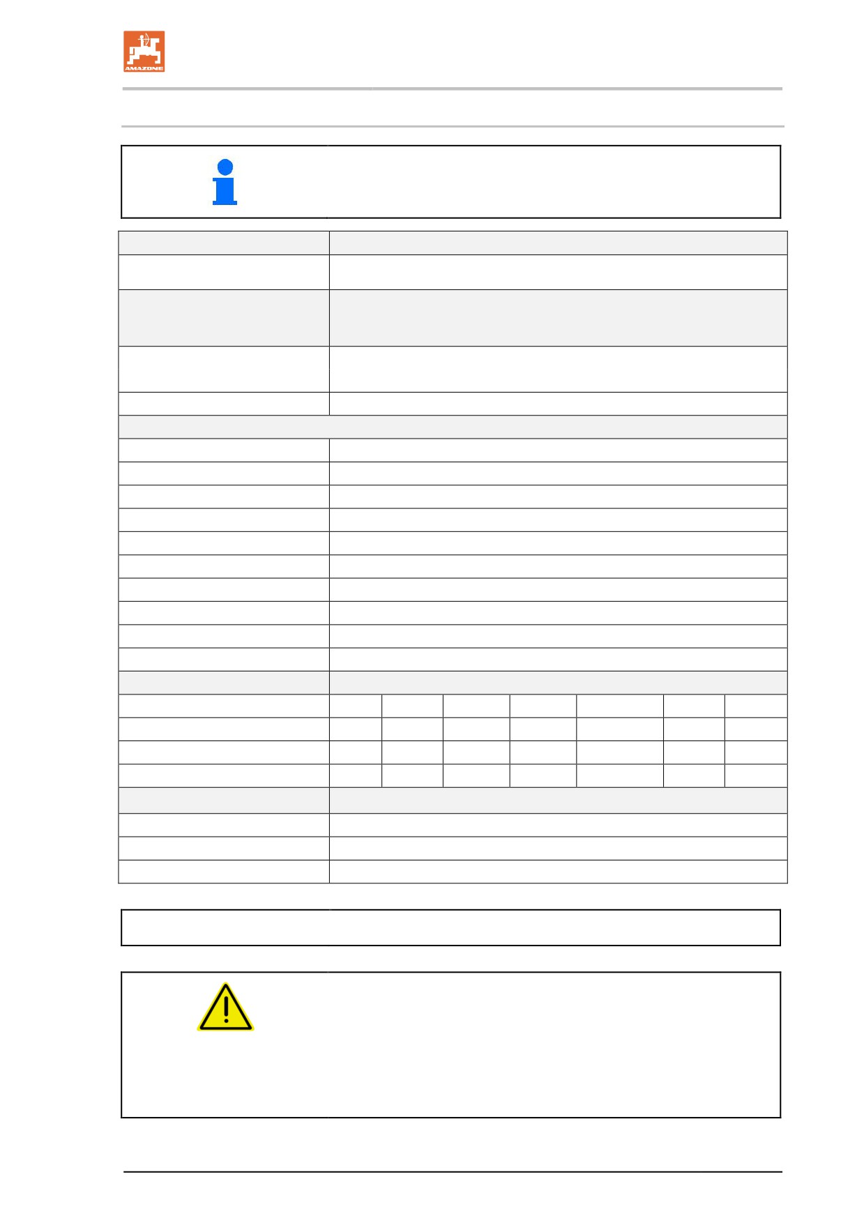
4.13.3 Weights basic machine and modules
The basic weight (empty weight) is calculated from the total individual
weights of the modules.
Typ
UX 11200
[kg]
Basic implement with pump
4285
equipment, brakes and cou-
pling device
Running gear
SingleTrail
990
DoubleTrail
1660
Tyres (4 units)
380/90 R46 (LI173A8/173D)
1080
380/90 R50 (LI175A8/175D)
1300
480/80 R46 (LI158A8/158B)
1480
480/80 R46 (LI177A8/177D)
1480
520/85 R42 (LI162A8/162B)
1560
520/85 R42 (LI169A8/165D)
1560
580/70 R42 (LI161A8/158D)
1640
650/65 R38 (LI164A8/161B)
1568
650/75 R38 (LI169A8/169B)
1760
650/65 R42 (LI168A8/165D)
1760
Sprayer boom
Working width m
21
24
27/19/10
27/22/15
27/21/15
28
28/15
Weight [kg]
750
760
764
932
932
765
936
Working width m
30/15
32
33
36
36/30/24/12
39
40
Weight [kg]
964
1008
1008
1032
1136
1136
1138
Spray lines
Part-width section control
18 - 42
single nozzle control
32 - 163
Other special equipment
Max. 300
Payload = permissible total weight - basic weight
DANGER
Exceeding the permitted payload is prohibited.
Risk of accident because of unstable driving conditions.
Carefully determine the payload, and therefore the permitted
filling amount for your machine. Not all filling media can be used
to fill the tank completely.
53
//////////////////////////////////////////