Amazone UX 11200 Trailed field sprayer. Operating Manual (2017) - page 2
Product description
4.13.4 Permissible total weight and tyres
The permissible total weight of the machine depends on the
•
permitted drawbar load
•
permitted axle load
•
permitted load capacity per pair of tyres
The permissible total weight is the total of
•
the permissible drawbar load and
•
the smaller value for the
ο permissible axle load of both axles
ο Load-bearing capacity of the tyres for both axles
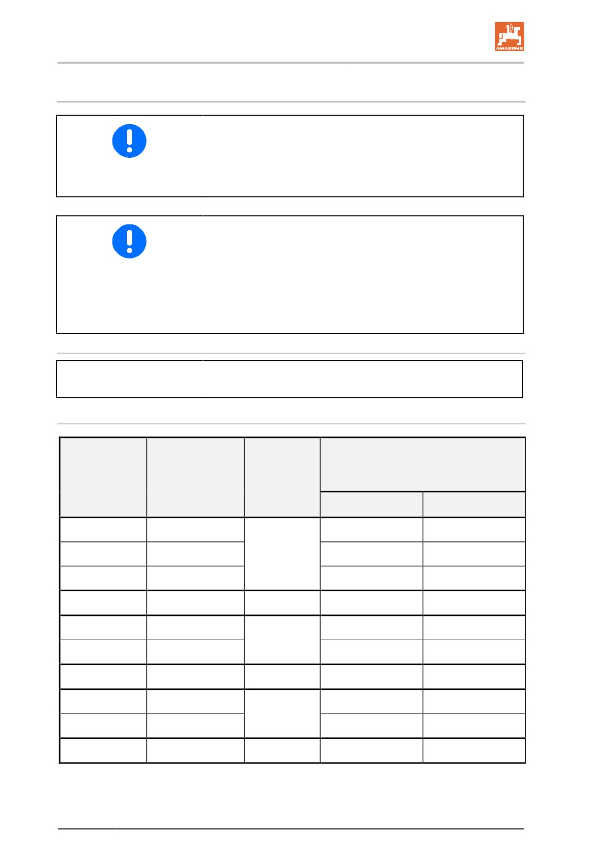
Please refer to the following tables for the values used for determining
the permissible total weight.
Permitted drawbar and axle load
Permitted drawbar load:
3000 kg
Permitted axle load (2 axle):
20000 kg
Load-bearing capacity of the tyres for both axles
permitted load capacity [kg]
(4 wheels)
Tyres
Load index
Nominal air
pressure
40 km/h
50 km/h
380/90 R50
175A8/175D
27600
27600
480/80 R46
158A8/158B
2,4
17000
17000
520/85 R42
169A8/165D
23200
20600
380/90 R46
173A8/173D
2,2
26000
26000
480/80 R46
177A8/177D
29200
29200
1,8
650/75 R38
169A8/169B
23200
23200
1,7
520/85 R42
162A8/162B
19000
19000
580/70 R42
161A8/158D
18500
17000
1,6
650/65 R38
164A8/161B
20000
18500
650/75 R38
169A8/169B
1,5
23200
23200
54
Product description
4.14
Noise emissions data
The workplace-related emissions value (acoustic pressure level) is 74
dB(A), measured during operation at the ear of the tractor driver with
the cab closed.
Measuring unit: OPTAC SLM 5.
The noise level is primarily dependent on the vehicle used.
55
Product description
4.15
Required tractor equipment
To be used with the machine, the tractor must fulfil the performance
requirements and be equipped with the required electrical, hydraulic
and brake connections for the brake system.
Tractor engine power
from 110 kW (150 bhp) upwards
Electrical system
Battery voltage:
•
12 V (volts)
Lighting socket:
•
7 pin
Hydraulic system
Maximum operating pressure:
•
210 bar
Tractor pump capacity:
•
min.25 l/min at 150 bar for hydraulic block (for Profi-folding,
optional)
•
min. 75 l/min at 150 bar for hydraulic pump drive (optional)
Implement hydraulic fluid:
•
HLP68 DIN 51524
The implement hydraulic fluid is suitable for the combined hydraulic
fluid circuits of all standard tractor brands.
Tractor control units
•
Depending on the equipment, see Seite 64.
Brake system (depending on equipment)
Dual circuit service brake sys-
•
1 hose coupling (red) for the supply line
tem:
•
1 hose coupling (yellow) for the brake line
or
Single circuit service brake
•
1 service line hose coupling for the brake line
system:
or
Hydraulic brake system:
•
1 hydraulic coupling, conforms to ISO 5676
The hydraulic brake system is prohibited in Germany and several
other EU countries.
Universal joint shaft (depending on equipment)
Required speed:
•
540 rpm
Direction of rotation:
•
Clockwise, viewed from rear toward the tractor.
56
Construction and function of the basic machine
5
Construction and function of the basic machine
5.1
Functionality
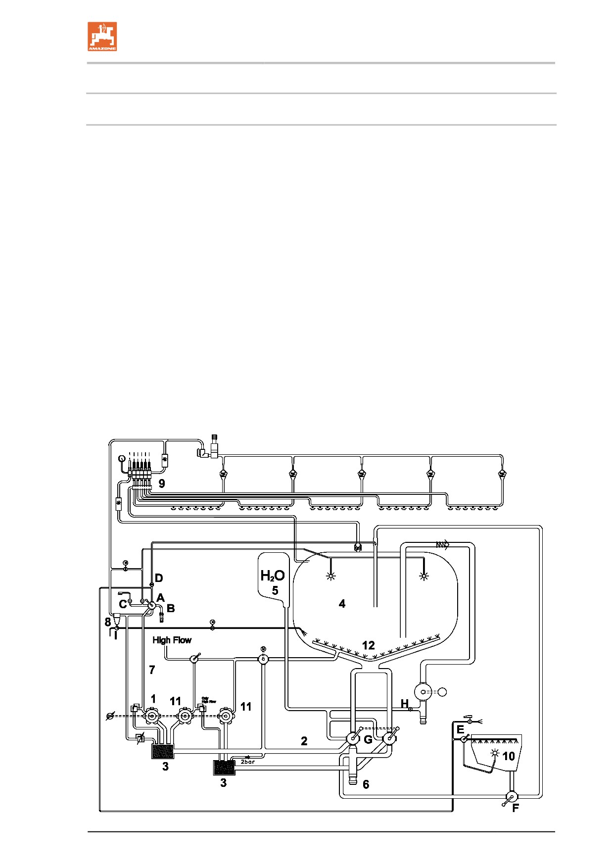
Fig. 19/...
Via the suction chest (G), suction line (2) and suction filter (3), the
spraying pump (1) sucks
•
the spray liquid from the spray liquid tank (4).
•
flushing water from the flushing water tank (5).
The flushing water serves to clean the spray system.
•
fresh water via the external suction port (6).
The liquid that has been drawn in is fed via the pressure hose (7) to
the pressure equipment switch tap (A), and from there is fed
•
via the self cleaning pressure filter (8) to the part width section
valves (9). The part width section valves then send the liquid to
separate spray lines.
Via the additional agitator setting tap (I) on the pressure filter, the
stirring performance can be increased when stirring spray liquid.
•
to the injector and induction bowl.
To prepare the spray liquid, pour the relevant quantity of agent
required to fill the spray liquid tank into the induction bowl (10)
and evacuate into the spray liquid tank.
•
directly into the spray liquid tank (4).
•
to the internal (B) or external cleaning switch tap (C).
The agitator pump (11) supplies the main agitator (12) in the spray
liquid tank. In its switched-on state, the main agitator ensures a ho-
mogeneous spray liquid in the spray liquid tank. The stirring perfor-
mance of the main agitator can be adjusted infinitely using the main
agitator setting tap (H).
Fig. 19
57
Construction and function of the basic machine
5.2
Control terminal
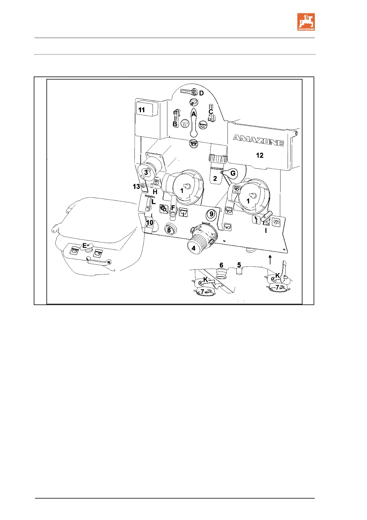
The relevant operation modes are set centrally on the control termi-
nal, using the various control elements.
Fig. 20
(A) Pressure equipment switch tap
(1) Suction filter
(B) Quick emptying switch tap
(2) Pressure filter
(C) External cleaning switch tap
(3) Flushing water tank filling connection / spray
liquid tank through pressure hose
(D) Injector switch tap
(4) Spray liquid tank filling connection via suction
(E) Ring line / canister flushing switch tap
hose 4”
(F) Switch tap - drawing off through injector
(5) Pressure filter outlet
(G) Suction port, electrically actuated
(6) Quick emptying via pump
(H) Switch tap - filling - flushing water tank
(7) Suction filter / spray liquid outlet
(I) Additional agitator / drain residue switch tap
(8) Rinsing pedestal Ecofill
(K) Suction filter / drain spray liquid switch tap
(9) Button actuation - suction port
(L) Ecofill switch tap
(10) Ecofill connection
(11) Filling level indicator
(12) Storage box
(13) Button - filling - spray liquid tank through pres-
sure hose
58
Construction and function of the basic machine
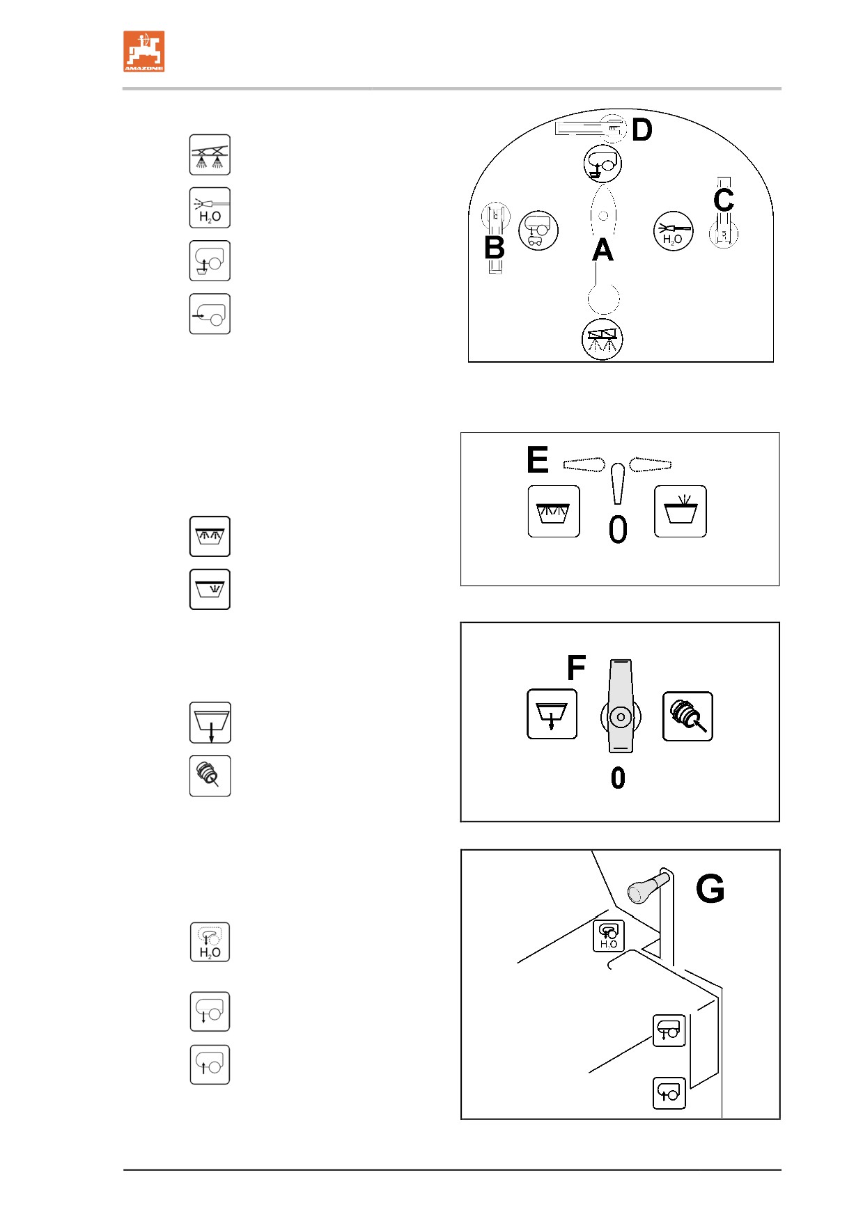
•
A - Pressure equipment switch tap
ο
Spraying operation
ο
Cleaning
ο
Injector mode
ο
Fill spray liquid tank
•
B - Quick emptying switch tap
Fig. 21
•
C - External cleaning switch tap
•
D - Injector switch tap
•
E - Ring line / canister flushing switch
tap
○
0 Zero setting
○
Ring line
Fig. 22
○
Canister flushing
•
F - Evacuate switch tap for induction
bowl / Cut in injector
○
0 Zero setting
○
Evacuate induction bowl
○
Draw in additionally from an ex-
ternal source via an injector:
Fig. 23
•
G - Suction chest
The suction port is electrically operated by the
button on the control or operating terminal.
○
Sucking from flushing water
tank
○
Sucking from spray tank
ο
Sucking via suction hose
Fig. 24
59
Construction and function of the basic machine
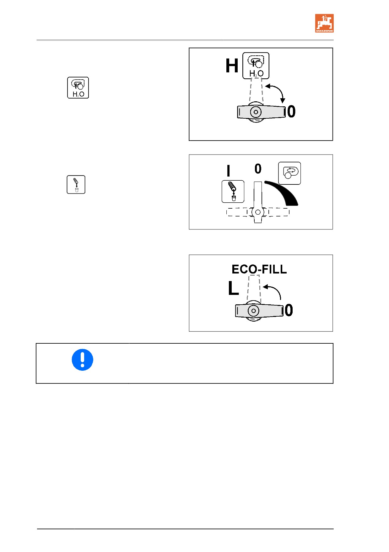
•
H - Switch tap - filling - flushing water
tank
ο
Filling with flushing water
ο
0 Zero setting
Fig. 25
•
I - Additional agitator switch tap
○
Release residue in the pressure
filter
Fig. 26
•
L - Ecofill switch tap
ο Ecofill Filling through Ecofill filling
connection
ο
0 Zero setting
All stop taps are
•
open when lever position is in direction of flow
•
closed when lever position is transverse to direction of flow
60
Construction and function of the basic machine
5.3
PTO shaft
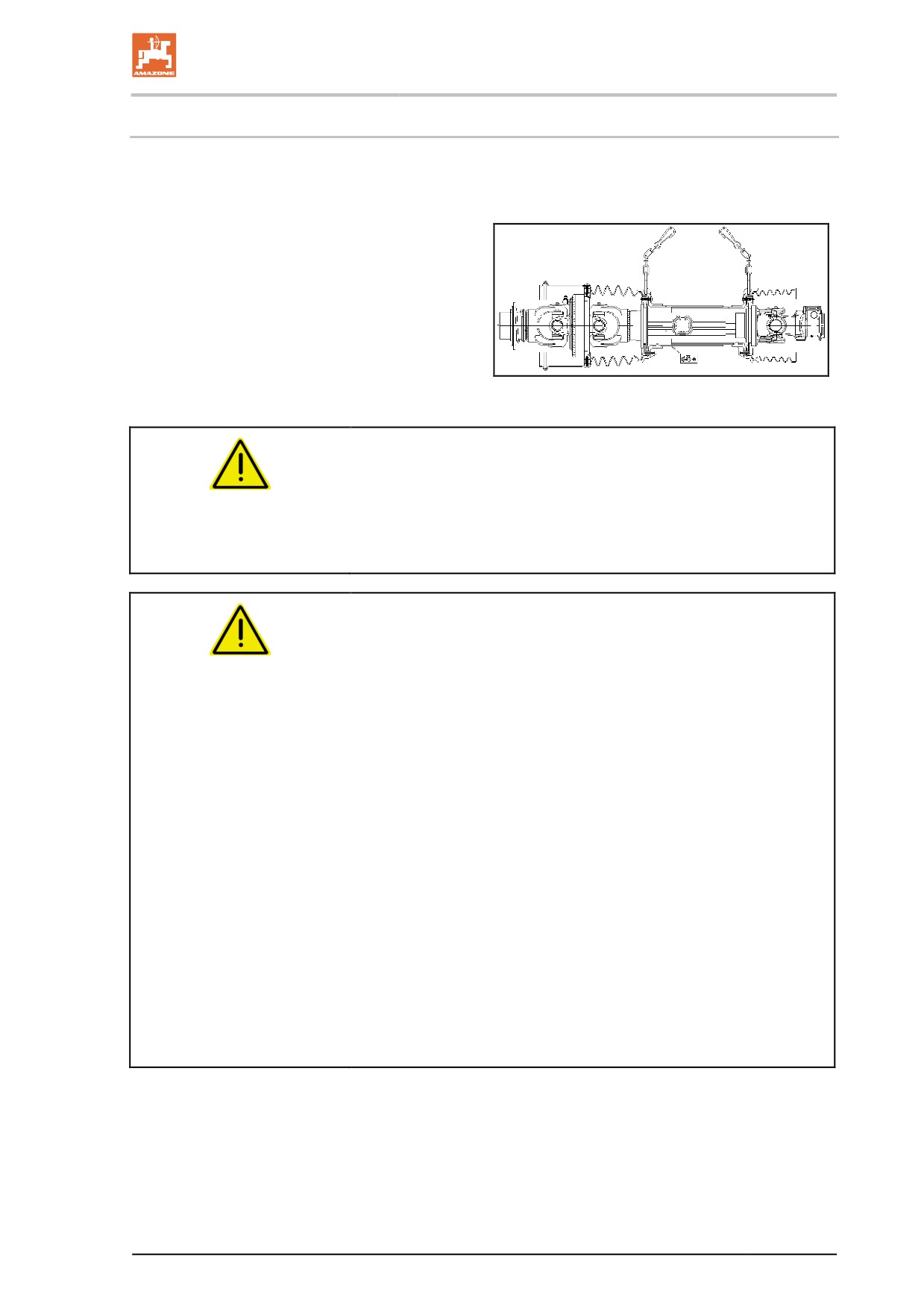
The wide angle PTO shaft takes on the power transmission between
tractor and machine.
Fig. 27:
•
Wide angle PTO shaft (860 mm) for straight
drawbar and hitch draw bar
•
Russia only:
Wide angle PTO shaft (860 mm) for straight
drawbar and hitch draw bar
•
Wide angle PTO shaft W100E (810 mm) for
open straight drawbar, hitched at the top
Fig. 27
WARNING
Risk of crushing from the tractor and machine unintentionally
starting up or rolling.
Only couple/uncouple the wide angle PTO shaft from the tractor, if the
tractor and machine are secured against unintentional starting and
rolling.
WARNING
Risk of being caught and drawn in by the unguarded PTO shaft
or due to damaged safety devices.
•
Never use the PTO shaft if the safety device is missing or dam-
aged, or without correctly using the supporting chain.
•
Before each use, check that
ο all PTO shaft protective devices are installed and fully func-
tional.
ο the clearance around the PTO shaft is sufficient in all oper-
ating positions. Insufficient clearance will result in damage
to the PTO shaft.
•
Attach the supporting chains in a way that ensures a sufficient
swivel range of the PTO shaft in all operating positions. Support-
ing chains must not become caught on machine or tractor parts.
•
Have any damaged or missing parts of the PTO shaft replaced
immediately with genuine parts from the PTO shaft manufactur-
er.
Note that only a specialist workshop may repair a PTO shaft.
•
With the machine uncoupled, place the PTO shaft in the holder
provided. This protects the PTO shaft from damage and dirt.
ο Never use the supporting chain of the PTO shaft to sus-
pend the uncoupled PTO shaft.
61
Construction and function of the basic machine
WARNING
Risk of being caught and drawn in by unguarded PTO shaft parts
in the power transmission area between the tractor and driven
machine.
Work only when the drive between the tractor and driven machine is
fully guarded.
•
The unguarded parts of the PTO shaft must always be guarded
by a shield on the tractor and a PTO shaft guard on the ma-
chine.
•
Check that the shield on the tractor or the PTO shaft guard on
the machine and the safety devices and guards of the extended
PTO shaft overlap by at least 50 mm. If they do not, you must
not power the machine via the PTO shaft.
•
Use only the PTO shaft provided or one of the same type.
•
Read and follow the operating manual provided for the PTO
shaft. Correct use and maintenance of the PTO shaft prevents
serious accidents.
•
When coupling the PTO shaft
ο refer to the operating manual provided for the PTO shaft.
ο observe the permissible drive speed of the machine.
ο observe the correct installation length of the PTO shaft. Re-
fer to the section "Adjusting the length of the PTO shaft to
the tractor", page 129.
ο observe the correct installation position of the PTO shaft.
The tractor symbol on the protective tube of the PTO shaft
identifies the tractor-side connection of the PTO shaft.
•
Always mount the overload or freewheel clutch on the machine if
the PTO shaft has an overload or freewheel clutch.
•
Before switching on the universal joint shaft, read and follow the
safety precautions for universal joint shaft operation in the sec-
tion "Safety information for the user", page 33.
62
Construction and function of the basic machine
5.3.1
Coupling the PTO shaft
WARNING
Risk of crushing or impact if there is insufficient clearance when
coupling the PTO shaft.
Couple the PTO shaft with the tractor before coupling the machine
with the tractor. This will ensure the necessary clearance for safe
coupling of the PTO shaft.
1. Drive the tractor up to the machine, leaving a clearance (approx.
25 cm) between the tractor and the machine.
2. Secure the tractor against unintentional starting and rolling, see
the section "Securing the tractor against unintentional starting
and rolling", starting on page 131.
3. Check whether the tractor universal joint shaft is switched off.
4. Clean and grease the tractor universal joint shaft.
5. Fit the latch of the PTO shaft over the universal joint shaft of the
tractor until the latch is heard to engage. When coupling the
PTO shaft, refer to the operating manual provided for the PTO
shaft and observe the permissible universal joint shaft speed of
the machine.
The tractor symbol on the protective tube of the PTO shaft identifies
the tractor-side connection of the PTO shaft.
6. Secure the PTO shaft guard using the supporting chain(s) to
prevent movement.
6.1 Fasten the supporting chain(s) so that it as perpendicular to
the PTO shaft as possible.
6.2 Attach the supporting chain(s) in a way that ensures suffi-
cient swivel range of the PTO shaft in all operating posi-
tions.
CAUTION
Supporting chains must not become caught on machine or tractor
parts.
7. Check that there is sufficient clearance around the PTO shaft in
all operating conditions. Insufficient clearance will result in dam-
age to the PTO shaft.
8. Provide the necessary clearance (if required).
63
Construction and function of the basic machine
5.3.2
Uncoupling the PTO shaft
WARNING
Risk of crushing or impact if there is insufficient clearance when
uncoupling the PTO shaft.
First uncouple the machine from the tractor before uncoupling the
PTO shaft from the tractor. This will ensure the necessary clearance
for safe uncoupling of the PTO shaft.
CAUTION
Risk of burning on hot components of the PTO shaft.
This danger can cause minor to serious injuries to the hands.
Do not touch components of the PTO shaft that have become hot
(particularly clutches).
•
Store the uncoupled PTO shaft in the holder provided. This pro-
tects the PTO shaft from damage and dirt.
Never use the supporting chain on the PTO shaft to hang up the
uncoupled PTO shaft.
•
Clean and lubricate the PTO shaft if it is going to be out of use
for a long time.
1. Uncouple the machine from the tractor. Refer to the section
"Uncoupling the machine", page 139.
2. Drive the tractor up to the machine, leaving a clearance of ap-
proximately 25 cm between the tractor and the machine.
3. Secure the tractor against unintentional starting and rolling, see
the section "Securing the tractor against unintentional starting
and rolling", starting on page 131.
4. Pull the latch of the PTO shaft off the universal joint shaft of the
tractor. Observe the operating manual supplied with the PTO
shaft when uncoupling the PTO shaft.
5. Place the PTO shaft in the holder provided.
6. Clean and lubricate the PTO shaft if it is not going to be used for
a longer period of time.
64
Construction and function of the basic machine
5.4
Hydraulic connections
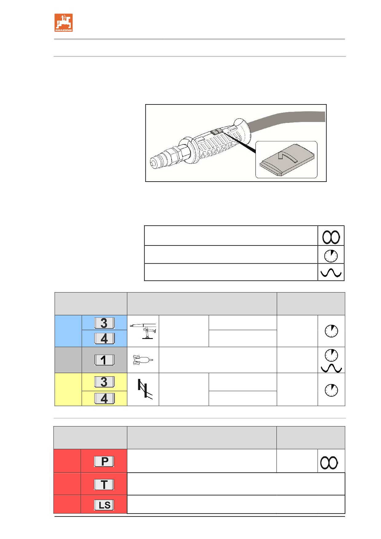
•
All hydraulic hose lines are equipped with grips.
Coloured markings with a code number or code letter have been
applied to the gripping sections in order to assign the respective
hydraulic function to the pressure line of a tractor control unit!
Films are stuck on the implement for the markings that illustrate
the respective hydraulic function.
•
The tractor control unit must be used in different types of activa-
tion, depending on the hydraulic function.
Latched, for a permanent oil circulation
Tentative, activate until the action is executed
Float position, free oil flow in the control unit
Folding using tractor
Function
Hose identification
control units
raise
stand
blue
(optional)
Double acting
lower
natural
SingleTrail
Single acting
raise
Lift modul
yellow
Double acting
(optional)
lower
Profi-Folding
Folding using tractor
Function
Hose identification
control units
red
Permanent oil circulation
Single acting
red
Pressure-free return flow
red
Load-Sensing-control line
65
Construction and function of the basic machine
WARNING
Risk of infection from hydraulic fluid escaping at high pressure.
When coupling/uncoupling the hydraulic hose line, ensure that the
hydraulic system is not under pressure on the tractor or machine side.
If you are injured by hydraulic fluid, contact a doctor immediately.
Profi-folding:
Maximum permissible pressure in oil return: 5 bar
Therefore do not connect the oil return to the tractor control unit, but
to a pressure-free oil return flow with a large plug coupling.
WARNING
For the oil return, use only DN16 lines and select short return
paths.
Pressurise the hydraulic system only when the free return has
been correctly coupled.
Install the coupling union (supplied) on the pressure-free oil return
flow.
Profi- folding LS:
The Profi-folding LS contains an accumulator and is provided for load-
sensing operation.
Using machines with hydraulic pump drive or Profi-folding LS in load-
sensing operation to get correct function of the hydraulic system.
5.4.1
Coupling hydraulic hose lines
WARNING
Risk of crushing, cutting, being trapped or drawn in, or impact
through faulty hydraulic functions when hydraulic hose lines are
incorrectly connected.
When coupling the hydraulic hose lines, please note the coloured
markings on the hydraulic plugs.
•
Check the compatibility of the hydraulic fluids before connecting
the machine to the tractor hydraulic system.
Do not mix any mineral oils with biological oils.
•
Observe the maximum permissible hydraulic fluid pressure of
210 bars.
•
Only couple clean hydraulic connectors.
•
Plug the hydraulic plug(s) into the hydraulic sockets until you can
feel the hydraulic plug(s) locking.
•
Check the coupling points on the hydraulic hose lines, to see if
they are sitting correctly and are sealed.
66
Construction and function of the basic machine
1. Swivel the actuation lever on the control valve on the tractor to
float position (neutral position).
2. Clean the hydraulic plugs on the hydraulic hose lines before
coupling the hydraulic hose lines with the tractor.
3. Connect the hydraulic hose line(s) to the tractor control unit(s).
5.4.2
Disconnecting hydraulic hose lines
1. Swivel the actuation lever on the tractor control unit on the trac-
tor to float position (neutral position).
2. Unlock the hydraulic connectors from the hydraulic sockets.
3. Protect the hydraulic plug and hydraulic socket against soiling
using the dust protection caps.
4. Store the hydraulic hose lines in the hose cabinet.
67
Construction and function of the basic machine
5.5
Air pressure brake system
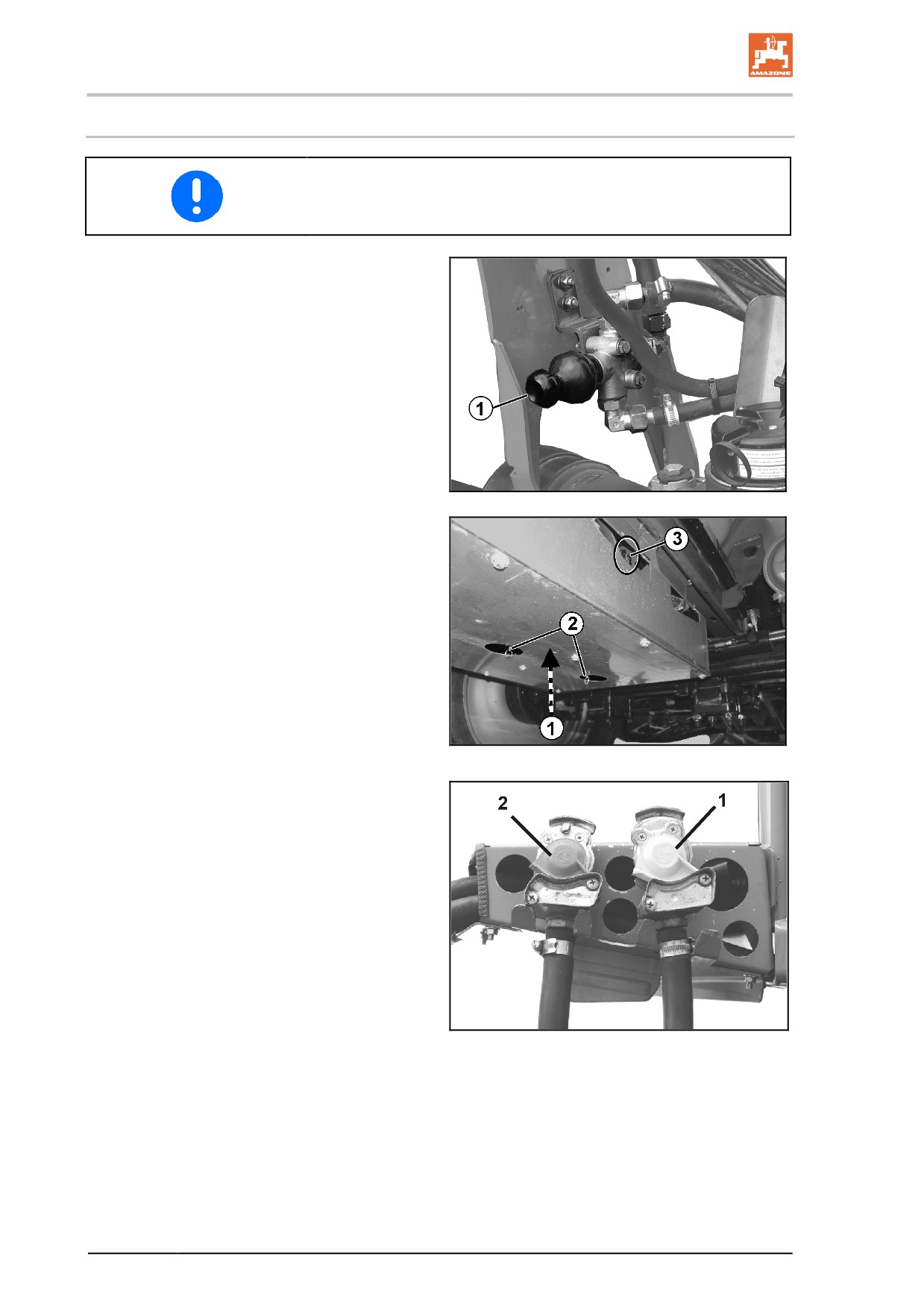
Keeping to the service interval is essential for proper functioning of
the dual circuit service brake system.
Fig. 29/...
(1) Actuator button;
○ press in until it stops and the service
brake system releases, e.g. for shunt-
ing the uncoupled trailed sprayer.
○ pull it out as far as it will go, and the
trailed sprayer is braked again by the
supply pressure coming from the air
reservoir.
Fig. 28
Fig. 30/...
(1) Air reservoir
(2) Drainage valve for condensate.
(3) Test connection
The brake drums are fitted with self regulating
brake levers that make sure that the wear to the
brake linings is compensated.
Fig. 29
Fig. 31/...
(1) Hose coupling on brake line (yellow)
(2) Hose coupling on supply line (red)
Fig. 30
68
Construction and function of the basic machine
5.5.1
Automatic load-dependent braking force regulator (ALB)
WARNING
Risk of crushing, cutting, being caught or drawn in, or impact
through incorrectly functioning brake system.
You must not change the adjustment measurement on the automatic
load-dependent braking force regulator. The adjustment measure-
ment must match the value given on the Haldex ALB plate.
The brake drums are fitted with self regulating brake levers that make
sure that the wear to the brake linings is compensated.
The axles are fitted with an automatic load-dependant braking force
regulator (ALB).
Input pressure: 6.5 bar
Setting data dependent on the axle load:
Axle load
Bellows pressure
Output pressure
(each axle)
[bar]
[bar]
[kg]
2 x 3650
35
3,1
2 x 9500
105
6,5
69
Construction and function of the basic machine
5.5.2
Coupling the brake system
WARNING
Risk of crushing, cutting, being caught or drawn in, or impact
through incorrectly functioning brake system.
•
When coupling the brake and supply line, ensure that
ο the sealing rings on the hose couplings are clean.
ο the sealing rings on the hose couplings seal properly.
•
Replace damaged sealing rings immediately.
•
Drain the air reservoir before the first transport of the day.
•
Only start up with the machine coupled if the pressure gauge on
the tractor shows 5.0 bar.
WARNING
Risk of crushing, cutting, being caught or drawn in, or impact
through the accidentally rolling machine, if the service brake is
released.
Dual-circuit pneumatic braking system:
•
Always couple the hose coupling on the brake line (yellow) first
and then the hose coupling on the supply line (red).
•
The service brake on the machine is immediately released from
the brake setting if the red hose coupling is coupled.
1. Open the cover on the hose coupling on the tractor.
2. Pneumatic braking system:
2.1 Fasten the brake line hose coupling (yellow) in the yellow
coupling on the tractor, as specified.
2.3 Fasten the supply line hose coupling (red) in the red cou-
pling on the tractor, as specified.
→ When coupling the supply line (red), the supply pressure
coming from the tractor automatically presses out the actu-
ator button for the release valve on the trailer brake valve
3. Loosen the parking brake and/or remove the wheel chocks.
70
Construction and function of the basic machine
5.5.3
Uncoupling the brake system
WARNING
Risk of crushing, cutting, being caught or drawn in, or impact
through from the accidentally rolling machine caused by unin-
tentionally releasing the service brake.
Dual-circuit pneumatic braking system:
•
Always uncouple the supply line hose coupling (red) first, and
then the brake line hose coupling (yellow).
•
The service brake of the machine only moves into the brake
position when the red hose coupling has been uncoupled.
•
Always keep to this order, otherwise the service brake system
will trip and may set the unbraked machine moving.
When the machine is uncoupled or pulled away from the trailer, air is
vented from the trailer brake valve supply line. The trailer brake valve
is automatically switched and operates the service braking system
independently of the automatic, load-dependent braking force regula-
tor.
1. Secure the machine against unintentionally rolling. To do this,
use the parking brake and/or wheel chocks.
2. Pneumatic braking system
2.1 Release the supply line hose coupling (red).
2.2 Release the brake line hose coupling (yellow).
3. Close the hose coupling covers on the tractor.
71
Construction and function of the basic machine
5.6
Hydraulic service brake system
To control the hydraulic service brake system, the tractor requires
hydraulic braking equipment.
5.6.1
Coupling the hydraulic service brake system
Only couple clean hydraulic couplings.
1. Remove the protective caps.
2. Clean the hydraulic plug and hydraulic socket if necessary.
3. Insert the tractor's hydraulic plug into the machine's hydraulic
socket.
4. Tighten the hydraulic screw union (if present) hand-tight.
5.6.2
Uncoupling the hydraulic service brake system
1. Loosen the hydraulic screw union (if present).
2. Protect the hydraulic plug and hydraulic socket against soiling
using the dust protection caps.
3. Store the hydraulic hose line in the hose cabinet.
5.6.3
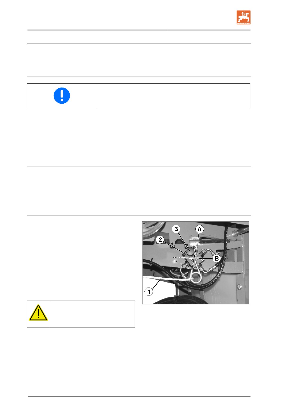
Emergency brake
In event of the machine being released from the
tractor during travel, the emergency brake will
brake the machine.
Fig. 32/…
(1) Pulling cable
(2) Brake valve with pressure accumulator
(3) Hand pump to relieve the brake
(A) Brake released
(B) Brake applied
DANGER
Fig. 31
Before travel, set the brake to the
application position.
72
Construction and function of the basic machine
For this purpose:
1. Secure the pulling cable to a fixed point on
the tractor.
2. Apply the tractor brake with the tractor en-
gine running and hydraulic brake connect-
ed.
→ Pressure accumulator of the emergency
brake is being charged.
DANGER
Risk of accident through brake malfunction!
After withdrawing the safety splint (e.g. when activating the emergen-
cy brake), it is essential to insert the safety splint into the brake valve
from the same side (Fig. 32). Otherwise the brake will not function.
After reinserting the safety splint, carry out a brake test for the service
brake and the emergency brake.
When the implement is uncoupled, the pressure accumulator presses
hydraulic oil:
•
into the brake and decelerates the implement,
or
•
into the hose line to the tractor and impedes the coupling of the
brake line to the tractor.
In these cases, relieve pressure using the hand pump on the brake
valve.
73
Construction and function of the basic machine
5.7
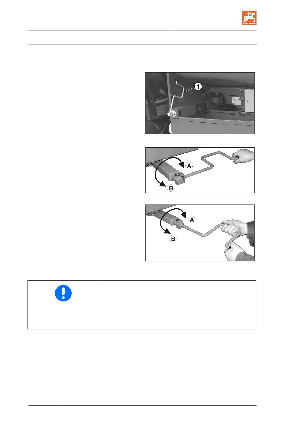
Parking brake
When the parking brake is on, it secures the uncoupled machine
against unintentional rolling. The parking brake is operated by turning
the crank, which in turn operates the spindle and bowden cable.
•
Crank; locked in idle position.
Fig. 32
•
Crank position for releasing / applying in the
end area.
(the parking brake requires approx. 20 kg
manual force to be applied).
Fig. 33
•
Crank position for quick releasing / apply-
ing.
(A)
Apply the tractor parking brake.
(B)
Release parking brake.
Fig. 34
•
Correct the setting of the parking brake if the spindle's tension is
no longer sufficient.
•
Ensure that the bowden cable is not lying or rubbing against
other vehicle parts.
•
When the parking brake is off, the bowden cable must be slightly
slack.
74
Construction and function of the basic machine
5.8
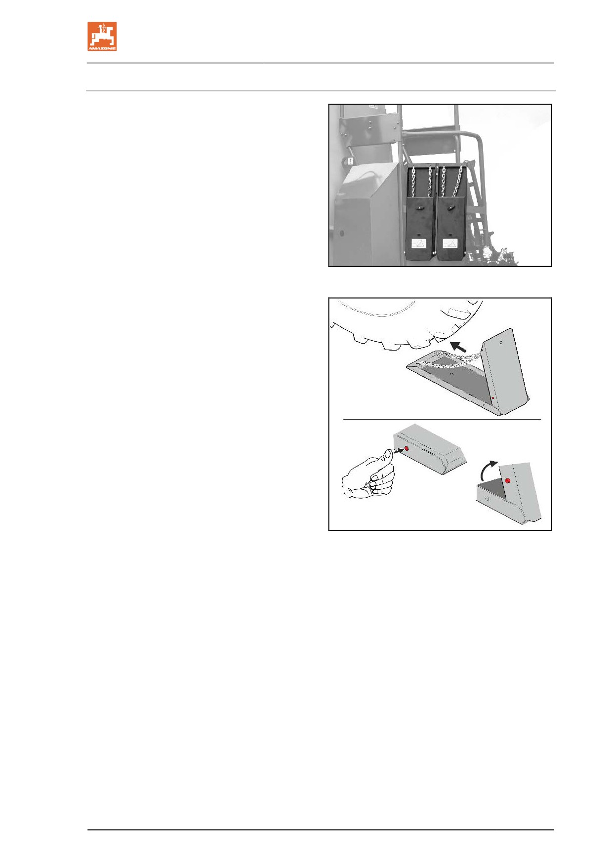
Foldable wheel chocks
Each of the wheel chocks is attached with a
thumb bolt on the right side of the implement.
Fig. 35
Put the foldable wheel chocks into operating posi-
tion by pressing the button and apply directly on
the wheels before uncoupling.
Fig. 36
75
Construction and function of the basic machine
5.9
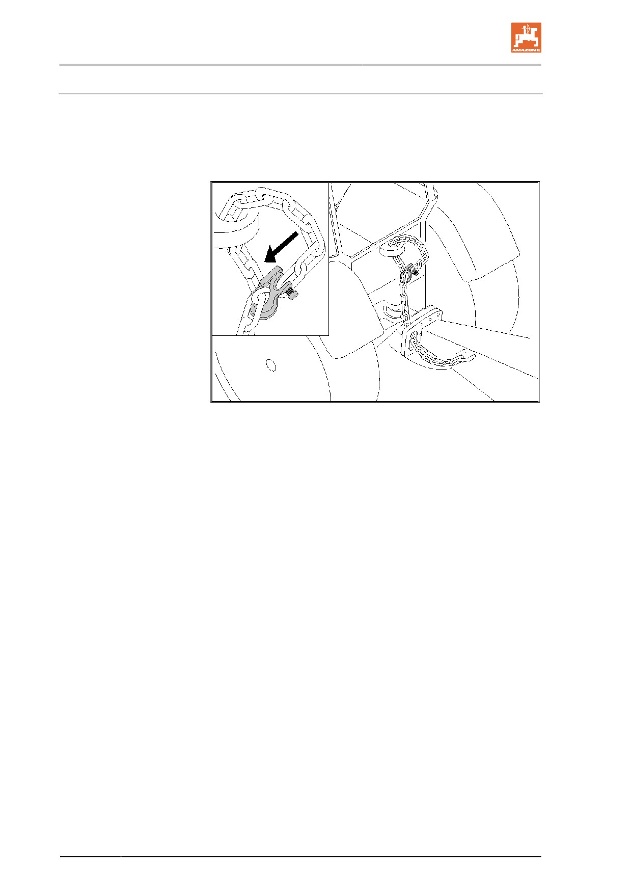
Safety chain for implements without brake system
Implements without a brake system or with a single-line brake system
must be equipped with a safety chain in compliance with local country
regulations.
The safety chain must be correctly fixed to a suitable position on the
tractor before transporting.
Fig. 37
76
Construction and function of the basic machine
5.10
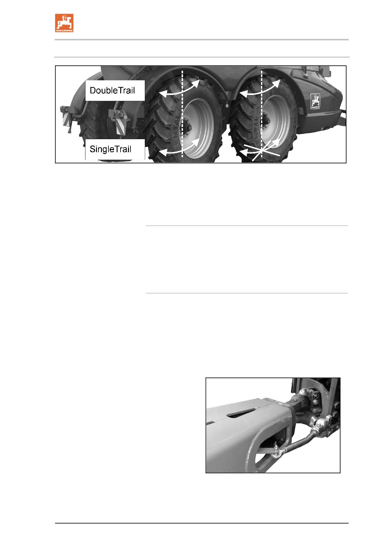
Tandem axle
Fig. 38
Depending on the equipment, the machine is fitted with the following
tandem axle:
•
a DoubleTrail tandem axle consisting of two steering axles
•
a SingleTrail tandem axle consisting of a fixed and a trailing axle
DoubleTrail tandem axle
With operating terminal for setting field, road, hillside location and
manoeuvring modes.
Field mode: both axles are hydraulically controlled and steered.
Road mode: The front axle is hydraulically blocked by the operating
terminal. The rear axle is hydraulically controlled and steered.
SingleTrail tandem axle
The front axle has been designed as a rigid axle.
The rear steering axle has been fitted with a connection to a tractor
control unit.
Field mode: The rear axle trails freely behind the tractor.
→ Operate the tractor control unit natural in a float position.
Road mode: Lock rear axle in centre position.
→ Actuate and lock the tractor control unit natural.
For speeds of less than 15 km/h, the axle may trail freely.
DoubleTrail tandem axle:
The angle of the machine to the tractor is detect-
ed by the handlebar with ball coupling head 50,
which is coupled to the tractor.
Fig. 39
77
Construction and function of the basic machine
5.11
Hydropneumatic sprung suspension (optional)
The hydropneumatic sprung suspension contains an automatic level
regulation device independent of the load status.
In manual mode, the machine can be lowered
•
to reduce the overhead clearance,
•
to switch off the sprung suspension.
WARNING
Danger of accident due to instable handling!
Always operate the hydro-pneumatic spring suspension in automatic
operation.
Please refer to the operating instructions for the operating terminal.
5.12
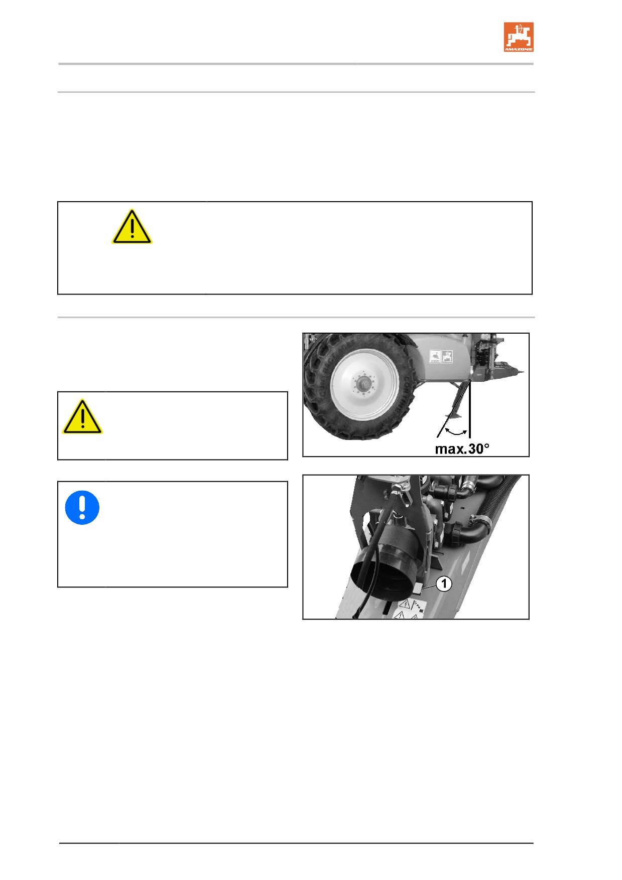
Hydraulic stand
The hydraulically operated stand (Fig. 42/1) sup-
ports the uncoupled trailed sprayer. It is operated
via a double-acting control valve.
Tractor control unit blue .
DANGER
When resting the machine on the
hydraulic stand, it must not be more
than 30° off the vertical.
Fig. 40
•
When operating the stand, step
on the tractor clutch to release
the pin from the yoke bar / hitch.
•
The red mark (Fig. 43/1) on the
stand control display is visible if
the machine is resting on the hy-
draulic stand.
Fig. 41
78
Construction and function of the basic machine
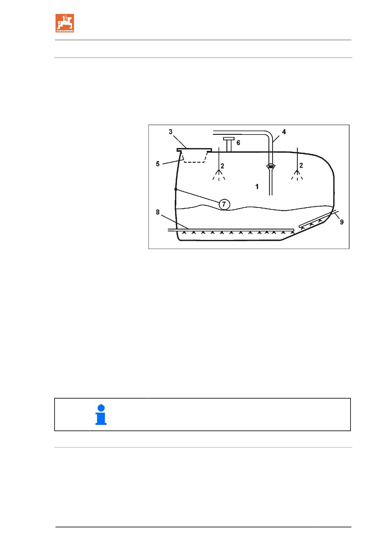
5.13
Spray liquid tank
The spray liquid tank is filled via
•
the filling opening,
•
the suction hose (optional) on the suction port,
•
the pressure filling connection (optional)
Fig. 42
(1) Spray liquid tank
(2) Internal cleaning
(3) Hinged/screw lid for filling opening
(4) External filling connection
(5) Filling sieve
(6) Ventilation
(7) Float for determining the fill level
(8) Agitator
(9) Additional agitator
(10) Shut-off valve to prevent unintended liquid escape in the event
of leaks
When using the machine, parts of the framework may chafe the spray
liquid tank. This does not affect the durability of the spray liquid tank.
Hinged/screw lid for the filling opening
•
To open the lid, rotate to the left and swing open.
•
To close the lid, fold down and rotate to the right until tight.
79
Construction and function of the basic machine
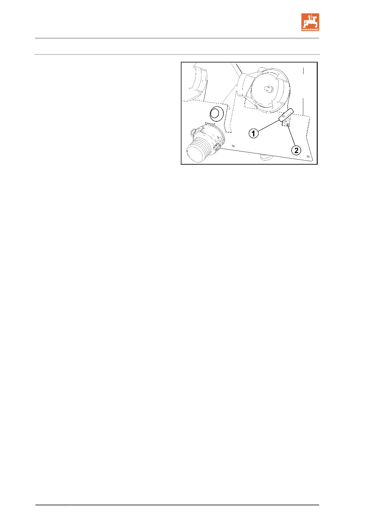
5.13.1 Agitators
When the agitators are switched on, they mix the
spray liquid in the spray liquid tank, thereby
providing a homogeneous spray liquid.
The field sprayer has been fitted with an auto-
matic main agitator (Rührmatik) and a manual
additional agitator. Both agitators are designed to
be hydraulic agitators.
Rührmatik (automatic agitator):
•
Remote control and regulation of the agita-
tion intensity.
Fig. 43
•
Manual control of the agitating intensity on
the operating terminal.
•
Automatic control of the main agitator de-
pending on the filling level.
•
Agitator shuts down automatically if the
filling level in the container falls below 5 %.
•
Two agitator pumps supply the main agita-
tor.
Additional agitator:
•
The additional agitator is supplied by the
operation pump.
•
The agitation power can be adjusted con-
tinuously at the switch tap (Fig. 45/1).
•
The additional agitator is simultaneously
combined with the pressure filter flushing
system for the self-cleaning pressure filter.
Lock for drainage function of the pressure
filter (Fig. 45/2).
80
Construction and function of the basic machine
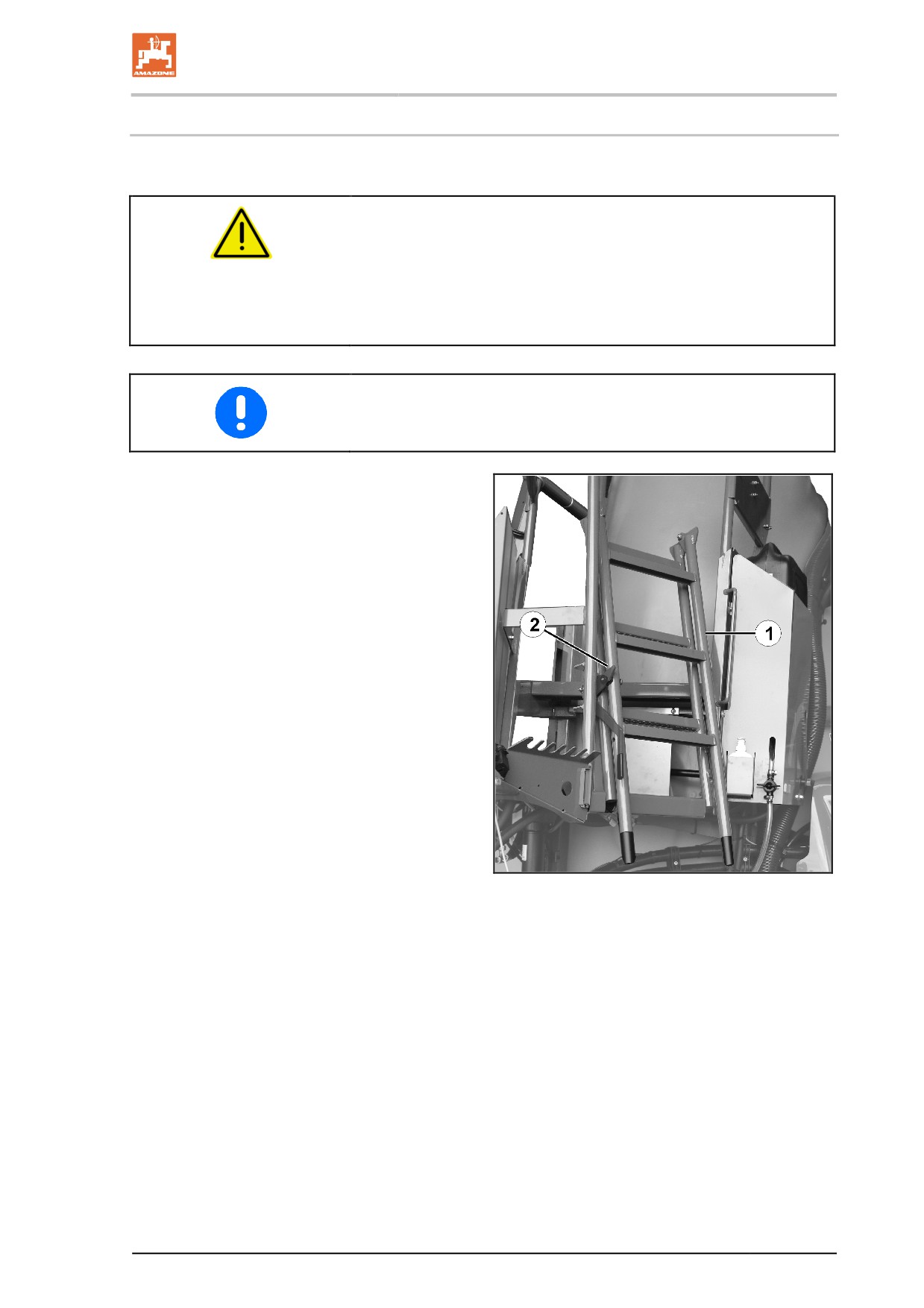
5.13.2 Maintenance platform with ladder
Maintenance platform with swivel-down ladder for reaching the filling
dome.
DANGER
•
Risk of injury from poisonous vapours.
Never climb into the spray liquid tank.
•
Riding on the machine creates a risk of falling.
Riding on the field sprayer is prohibited.
You MUST ensure that the ladder is locked in transport position.
Fig. 46/...
(1) Folded up ladder secured in transport posi-
tion.
(2) Automatic catch
To unlock the automatic catch, lift the lever
up.
Fig. 44
81
Construction and function of the basic machine
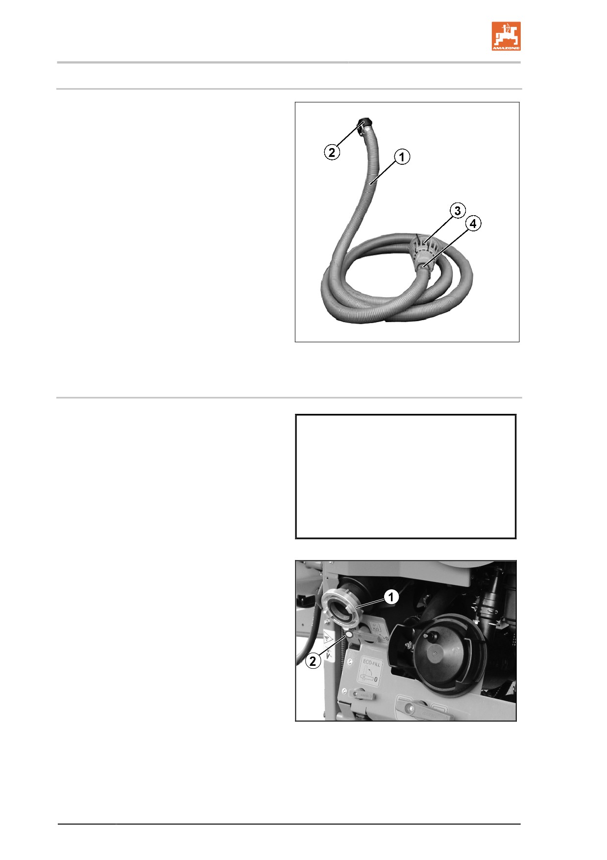
5.13.3 Suction port for filling the spray liquid tank (optional)
Fig. 47/...
(1) Suction hose (8 m, 3").
(2) Quick coupling.
(3) Suction filter for filtering the intake water.
(4) Non-return valve. Prevents liquid already in
the spray liquid tank from running out if the
vacuum suddenly collapses during the filling
process.
Filling stop:
When the required filling amount has been
reached, the filling process is stopped automati-
cally.
Fig. 45
5.13.4 Filling connection for filling the spray liquid tank with pressure (option)
•
Filling with free flow path and swivel spout
(Fig. 48).
•
Return flow safe direct filling, not approved
for filling from a public water supply net-
work.
Fig. 46
Fig. 49:
(1) Pressure filling connection
(2) Start / stop button for filling
Fig. 47
82
Construction and function of the basic machine
5.14
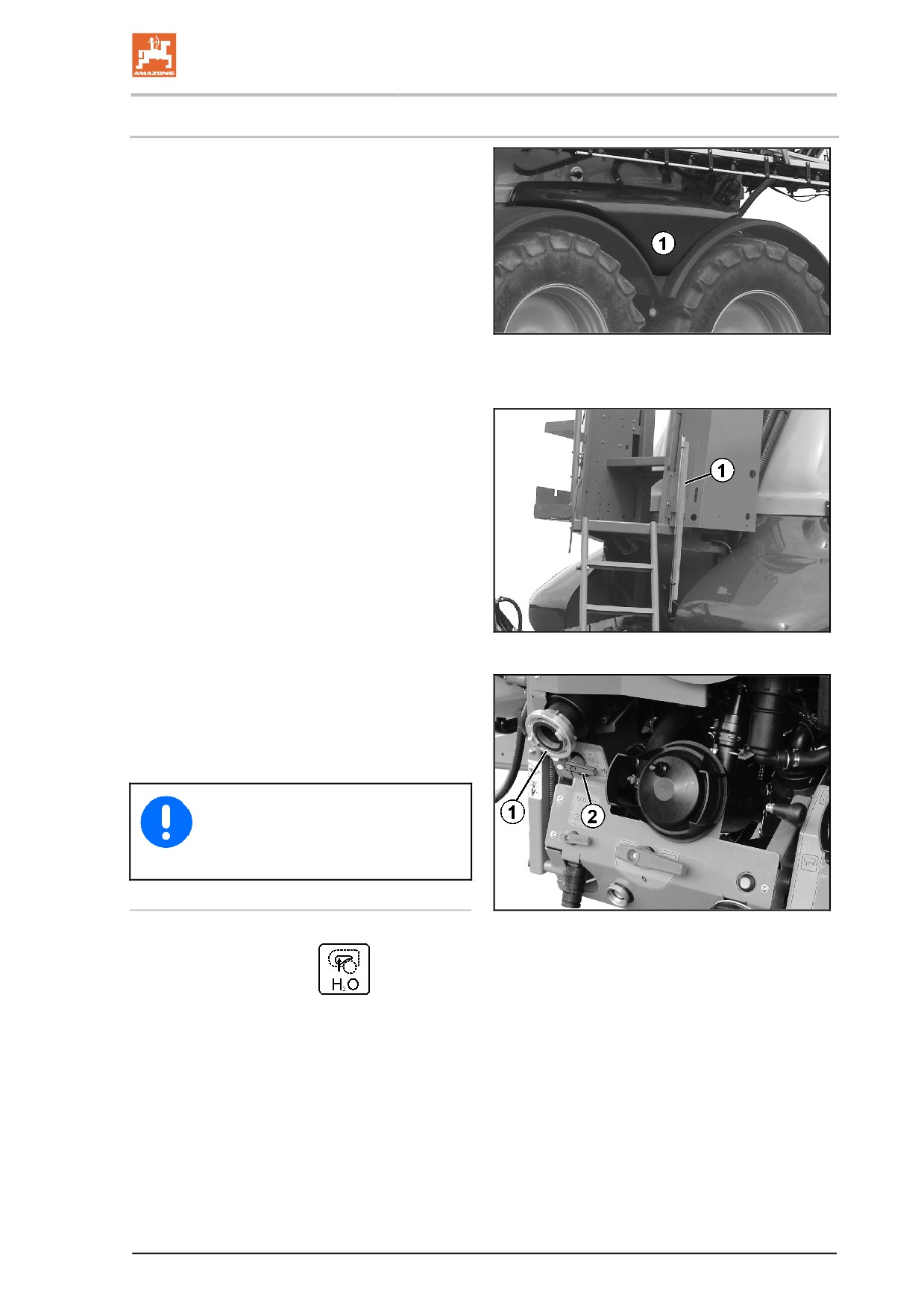
Flushing water tank
Clear water is also fed into the flushing water
tank. The water serves to
•
thin the residue in the spray liquid tank at
the end of spraying operation.
•
clean (flush) the whole field sprayer in the
field.
•
clean the suction chest and the spray lines
when the tank is full.
two connected flushing water tanks.
(900 l total capacity)
Fig. 48
Fig. 50/1: Flushing water tank
Fig. 51/1: Fill level indicator
Fig. 49
Fig. 52/…
(1) Pressure filling connection
(2) Switch tap - filling - flushing water tank
Only fill the flushing water tank with
clear fresh water.
Filling the flushing water tank
1. Connect filling hose.
Fig. 50
2. Switch tap in position
3. Fill the flushing water tank via the filling
connection (observe fill level display).
83
Construction and function of the basic machine
5.15
Induction bowl with canister flushing
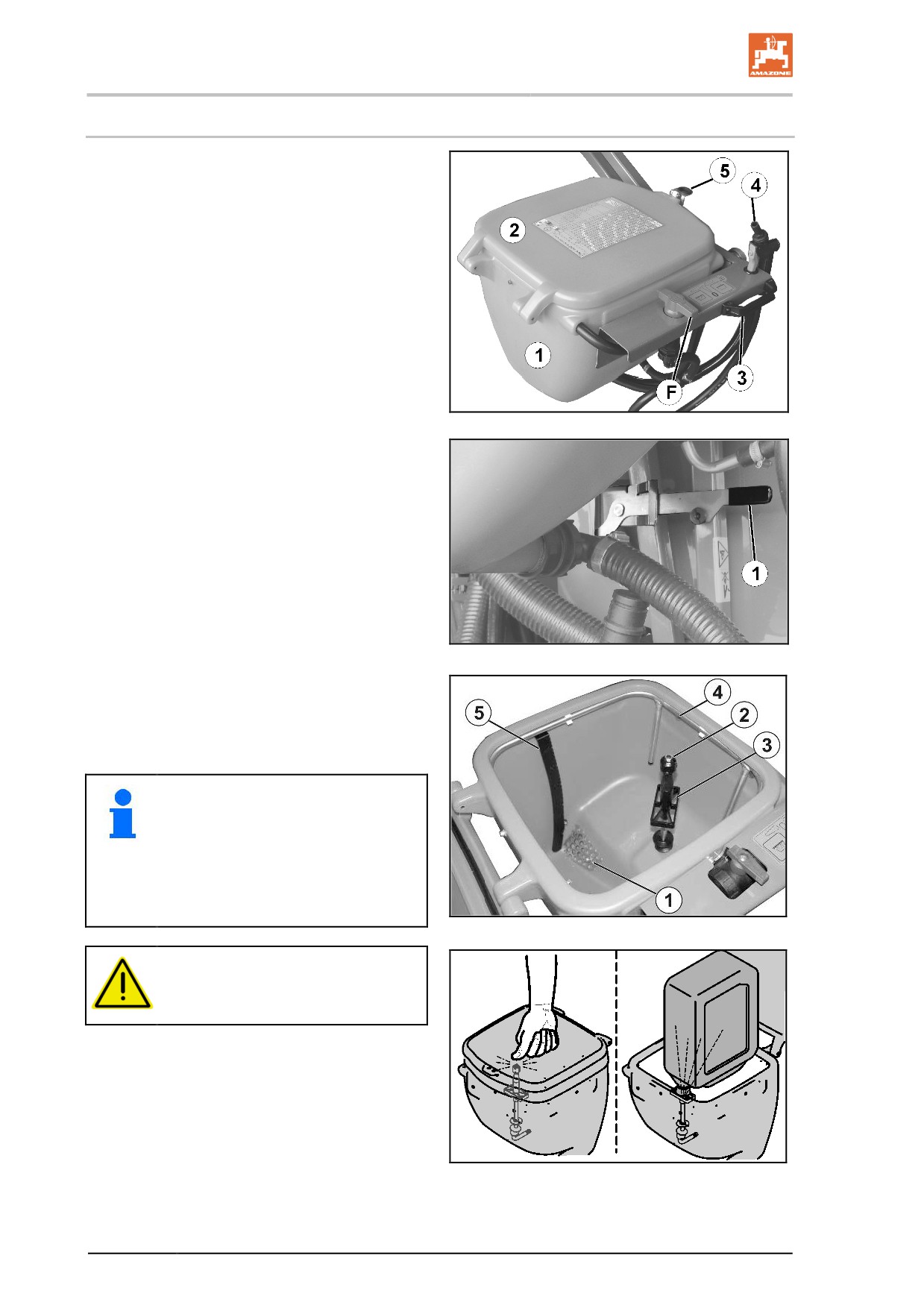
Fig. 53/...
(1) Swivel-out induction bowl for receiving,
dissolving and drawing in crop protection
agents and urea.
(2) Hinged lid.
(3) Handle for swivelling the induction bowl.
(4) Spray gun.
(5) Hinged lid catch
(F) Switch tap for ring line / canister flushing.
Fig. 54/...
Induction bowl with transport safety catch for
preventing the induction bowl from being swiv-
elled down while in transport position.
Fig. 51
To swivel the induction bowl in filling position:
1. Take hold of the handle on the induction
bowl.
2. Unlock transport safety catch (Fig. 54/1).
3. Swivel the induction bowl down.
Fig. 55/...
(1) The bottom sieve in the induction bowl pre-
vents lumps and foreign objects from being
drawn in
(2) Rotating canister flushing nozzle for wash-
Fig. 52
ing out canisters or other containers.
(3) Pressure plate.
(4) Ring line to dissolve and induct crop protec-
tion agent and urea.
(5) Scale
Water escapes from the canister flush-
ing nozzle if
•
the pressure plate is pressed
downwards.
•
the closed hinged lid presses the
canister flushing nozzle down-
wards.
Fig. 53
WARNING
Close the hinged lid before rinsing
the induction bowl.
Fig. 54
84
Construction and function of the basic machine
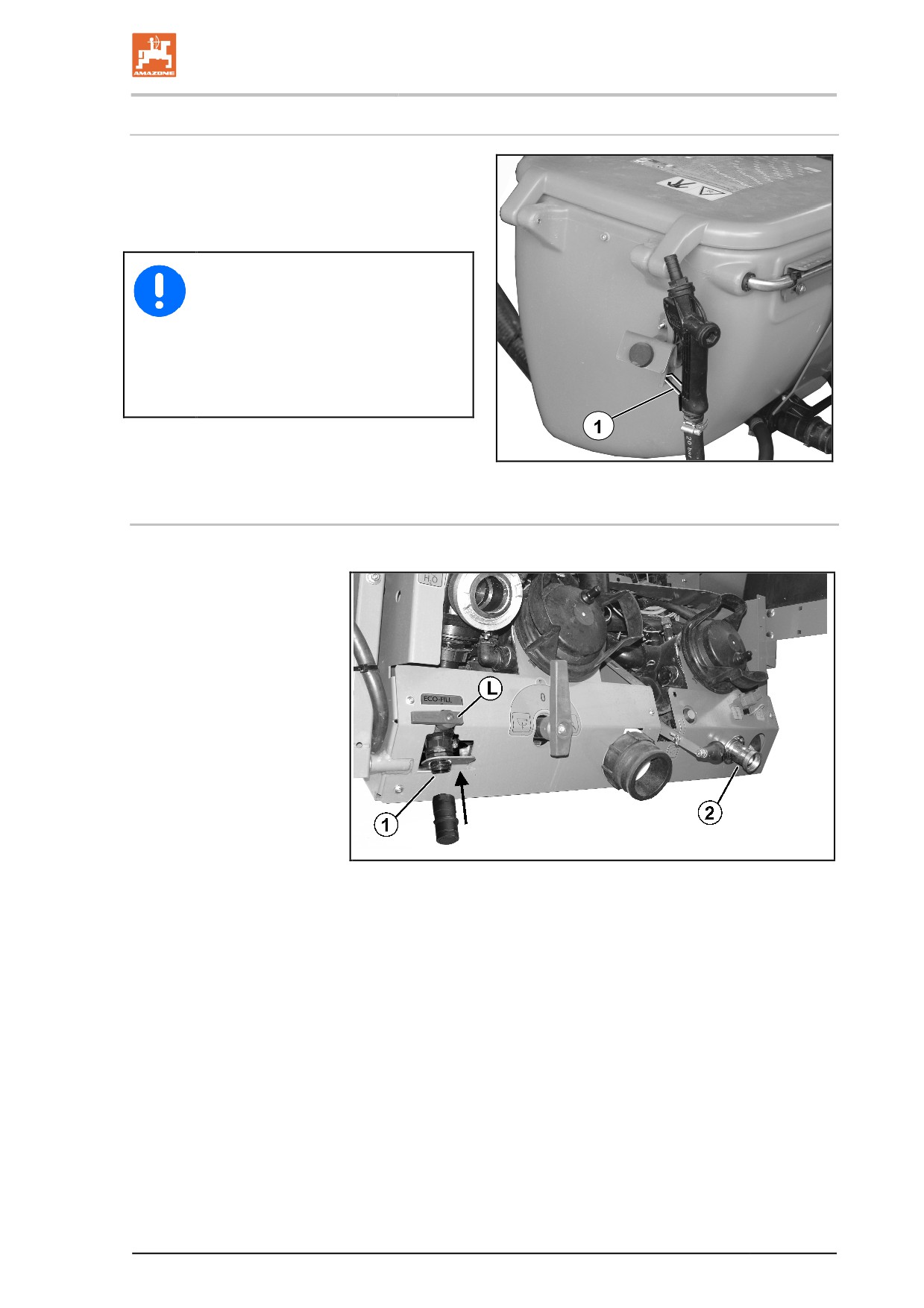
Spray gun for flushing the induction bowl
The spray gun is used for flushing the induc-
tion bowl with flushing water during or after
the flushing process.
Secure the spray gun against unin-
tentional spraying using the locking
mechanism (Fig. 57/1)
• before each pause in spraying.
• before depositing the spray
gun in its holder after cleaning
work is complete.
Fig. 55
5.16
Filling connection for Ecofill (optional)
Ecofill - connection for extracting spraying agent from Ecofill -tanks.
Fig. 56
(1) Ecofill filling connection (optional)
(2) Flushing port for Ecofill counter.
(L) Ecofill switch tap
85
Construction and function of the basic machine
5.17
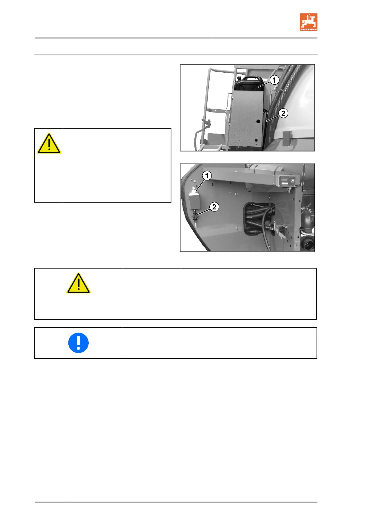
Fresh water tank
Fig. 59/…
(1) Fresh water holdertank capacity: 20l)
(2) Hose
WARNING
Danger of poisoning from using
unclean water in the fresh water
Fig. 57
tank.
Never use the water from the fresh
water tank as drinking water. The ma-
terials used to construct the fresh wa-
ter tank are not food-safe.
Fig. 60/…
(1) Soap dispenser
(2) Drain tap for clear fresh water
ο for cleaning hands or
ο for cleaning the spraying nozzles.
Fig. 58
WARNING
Inadmissible contamination of the clear water tank with crop
protection agent or spray liquid!
Always fill the clear water tank with clear freshwater only, and never
with crop protection agent or spray liquid.
When using the field sprayer, make sure that there is always an ade-
quate supply of clear freshwater. Check and also fill the freshwater
tank when you fill the spray liquid tank.
86
Construction and function of the basic machine
5.18
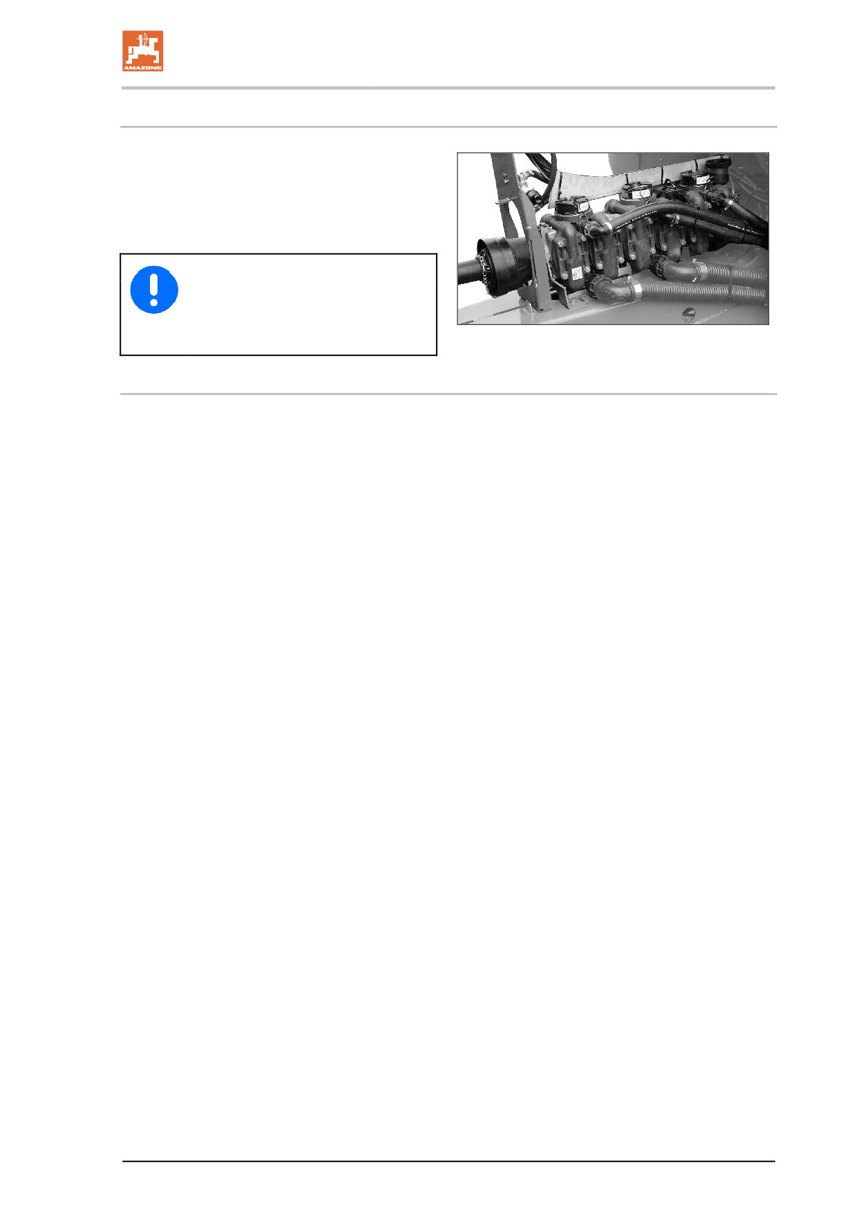
Pump equipment
All components that come into direct contact with
crop protection agents are produced from die-
cast aluminium with a plastic coating, or from
plastic. Based on the current state of knowledge,
these pumps are suitable for spreading standard
crop protection agents and liquid fertilisers.
Never exceed the maximum permissi-
ble pump drive speed of
540 1/min!
Fig. 59
5.18.1 Hydraulic pump drive
•
The maximum pump speed is hydraulically limited to 540 rpm.
•
For low pump speeds, reduce the oil flow from the tractor side.
•
The pump speed is displayed on the operating terminal.
87
Construction and function of the basic machine
5.19
Filter equipment
•
Use all the filters provided with the filter equipment. Clean the
filters regularly (refer to the "Cleaning" section, page 188). Fault-
free field sprayer operation can only be achieved by correct filter-
ing of the spray liquid. Correct filtering has a significant effect on
the success of the crop protection measures.
•
Pay attention to the permissible combinations of filters and mesh
sizes. The mesh sizes for the self cleaning pressure filter and the
nozzle filters must always be smaller than the nozzle opening of
the nozzles in question.
•
Ensure that the use of pressure filter inserts with 80 or
100 mesh / inch for some crop protection agents can filter out
active agents. In individual cases, enquire with crop protection
agent manufacturers.
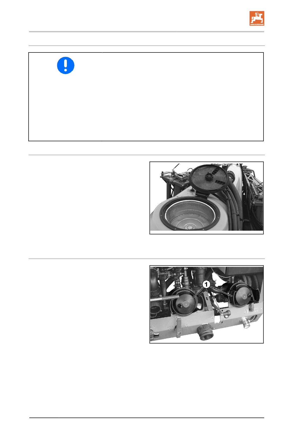
5.19.1 Filling sieve
The filling sieve prevents the spray liquid from
becoming contaminated while filling the spray
liquid tank via the filling dome.
Mesh size:
1.00 mm
Fig. 60
5.19.2 Suction filter
The suction filter (Fig. 63/1) filters
•
the spray liquid during the spraying opera-
tion.
•
the water when filling the spray liquid tank
via the suction hose.
Mesh size:
0.60 mm
Fig. 61
88
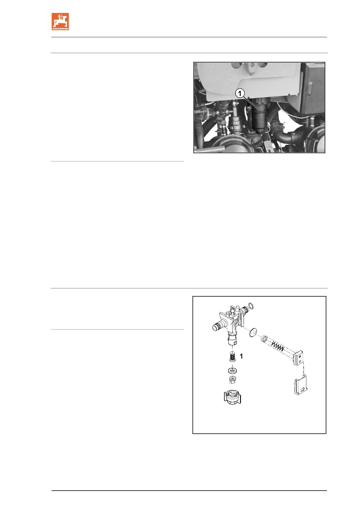
Construction and function of the basic machine
5.19.3 Self cleaning pressure filter
The self cleaning pressure filter (Fig. 64/1)
•
prevents the nozzle filter upstream of the
spraying nozzle from becoming blocked.
•
has a greater mesh count/inch than the
suction filter.
With the additional agitator switched on, the in-
side surface of the pressure filter insert is con-
stantly rinsed through, and undissolved particles
of spraying agent and dirt are conveyed back
into the spray liquid tank.
Overview of the pressure filter inserts
Fig. 62
•
50 mesh/inch (standard),
for nozzle size '03' and larger
Filter area:
216 mm²
Mesh size:
0.35 mm
•
80 mesh/inch,
for nozzle size '02'
Filter area:
216 mm²
Mesh size:
0.20 mm
•
100 mesh/inch
for nozzle size '015' and smaller
Filter area:
216 mm²
Mesh size:
0.15 mm
5.19.4 Nozzle filters
The nozzle filters (Fig. 65/1) prevent the spraying
nozzle from becoming blocked.
Overview of the nozzle filters
•
24 mesh/inch,
for nozzle size '06' and larger
Filter area:
5.00 mm²
Mesh size:
0.50 mm
•
50 mesh/inch (standard),
for nozzle size '02' to '05'
Filter area:
5.07 mm²
Mesh size:
0.35 mm
•
100 mesh/inch,
for nozzle size '015' and smaller
Filter area:
5.07 mm²
Mesh size:
0.15 mm
Fig. 63
89
Construction and function of the basic machine
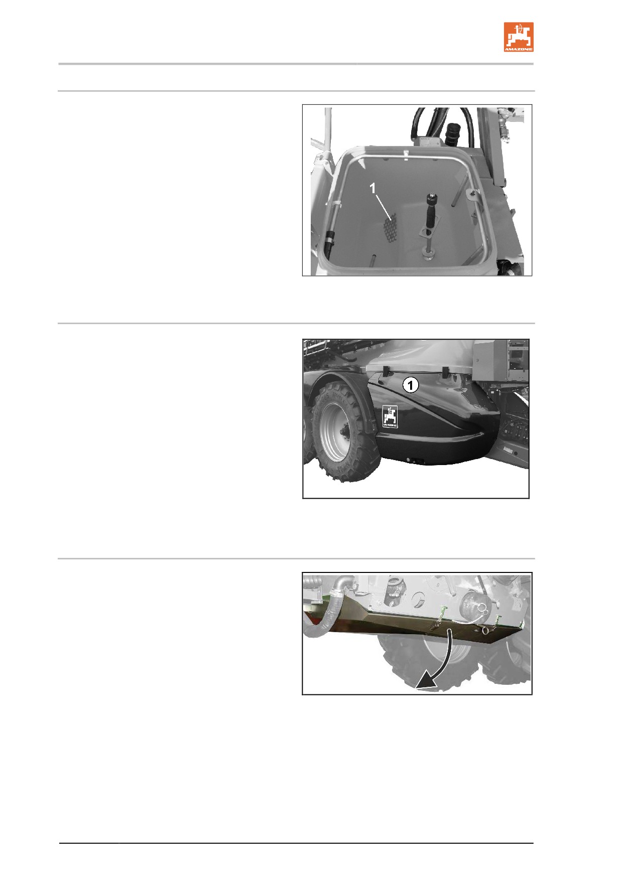
5.19.5 Bottom sieve in the induction bowl
The bottom sieve (Fig. 66/1) in the induction
bowl prevents lumps and foreign bodies from
being drawn in.
Fig. 64
5.20
Transport and secure container (optional)
Transport and secure container (Fig. 67/1) for
storing protective clothing and accessories.
Fig. 65
5.21
Crop protection underside (optional)
The crop protection underside can be folded on
the left side and thus allows access for draining
the field sprayer.
Fig. 66
90
Construction and function of the basic machine
5.22
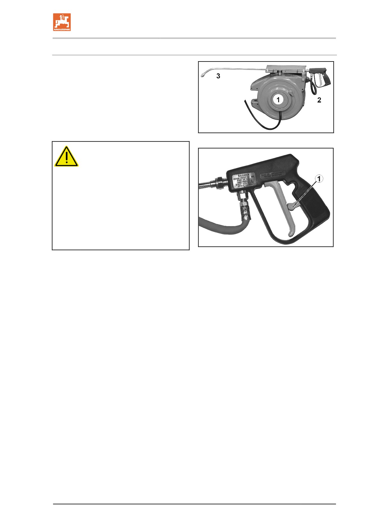
Exterior wash down kit (optional)
Fig. 68/…
Exterior wash down kit for cleaning the field
sprayer, includes
(1) Hose coiler,
(2)
20 m pressure hose,
(3) Spray gun
Operating pressure: 10 bar
Water output: 18 l/min
Fig. 67
WARNING
Danger from liquids escaping under
pressure and contamination with
spray liquid if the spray gun is acti-
vated accidentally.
Secure the spray gun against uninten-
tional spraying using the locking
mechanism (Fig. 69/1)
•
before each pause in spraying.
•
before depositing the spray gun
in its holder after cleaning work is
complete.
Fig. 68
91
Construction and function of the basic machine
5.23
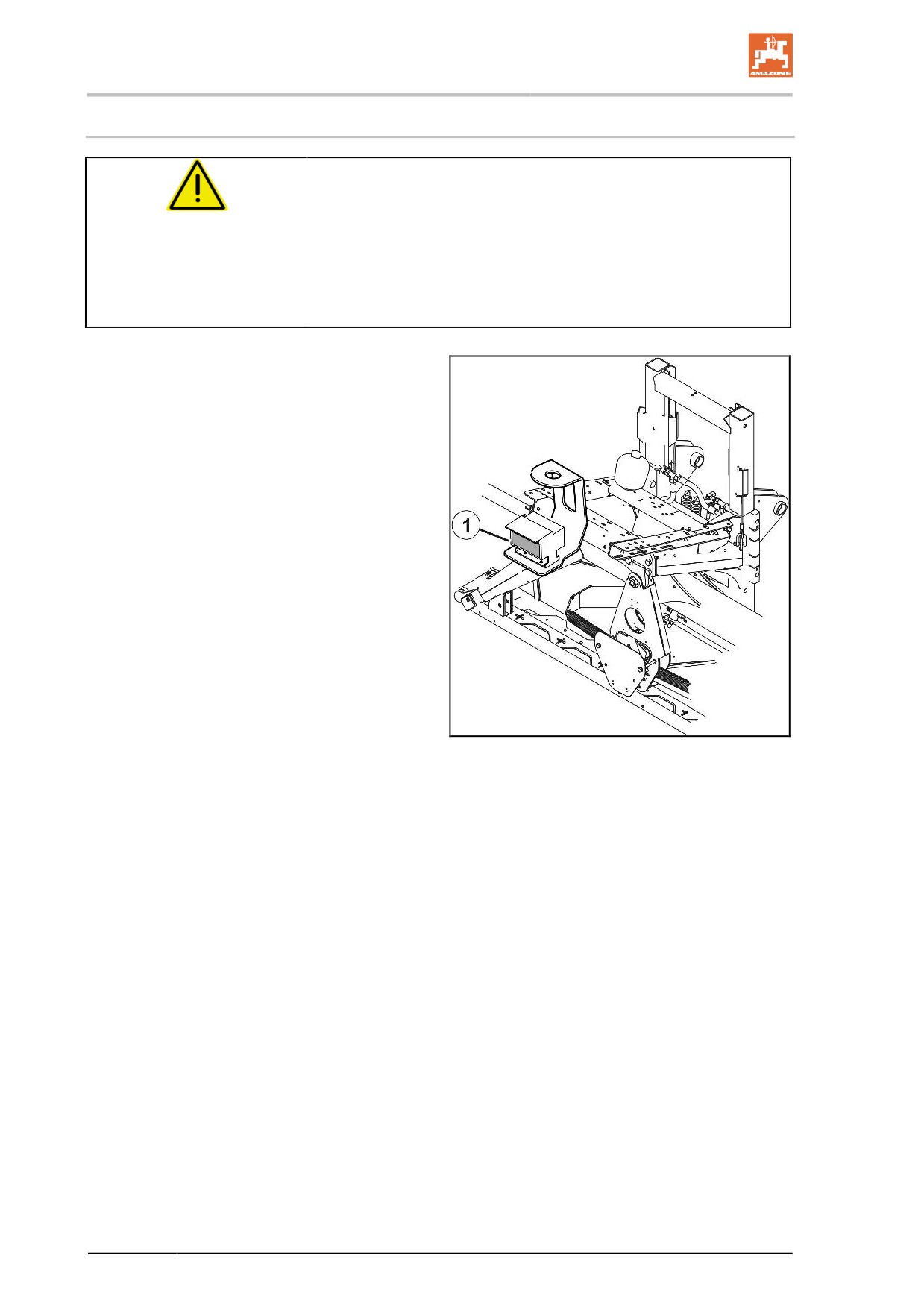
Camera system
WARNING
Risk of injury or even death.
If the camera display only is used for manoeuvring, persons or objects
can be overlooked. The camera system is an aid. It does not replace
the operator's awareness of the immediate surroundings.
•
Before manoeuvring, ensure that there are no people or
objects in the manoeuvring area by taking a direct look
The implement can be equipped with (Fig. 70/1)
a camera.
Features:
•
Viewing angle of 135°
•
Heater and lotus coating
•
Infrared night-view technology
•
Automatic backlight compensation
Fig. 69
92
Construction and function of the basic machine
5.24
Work floodlights
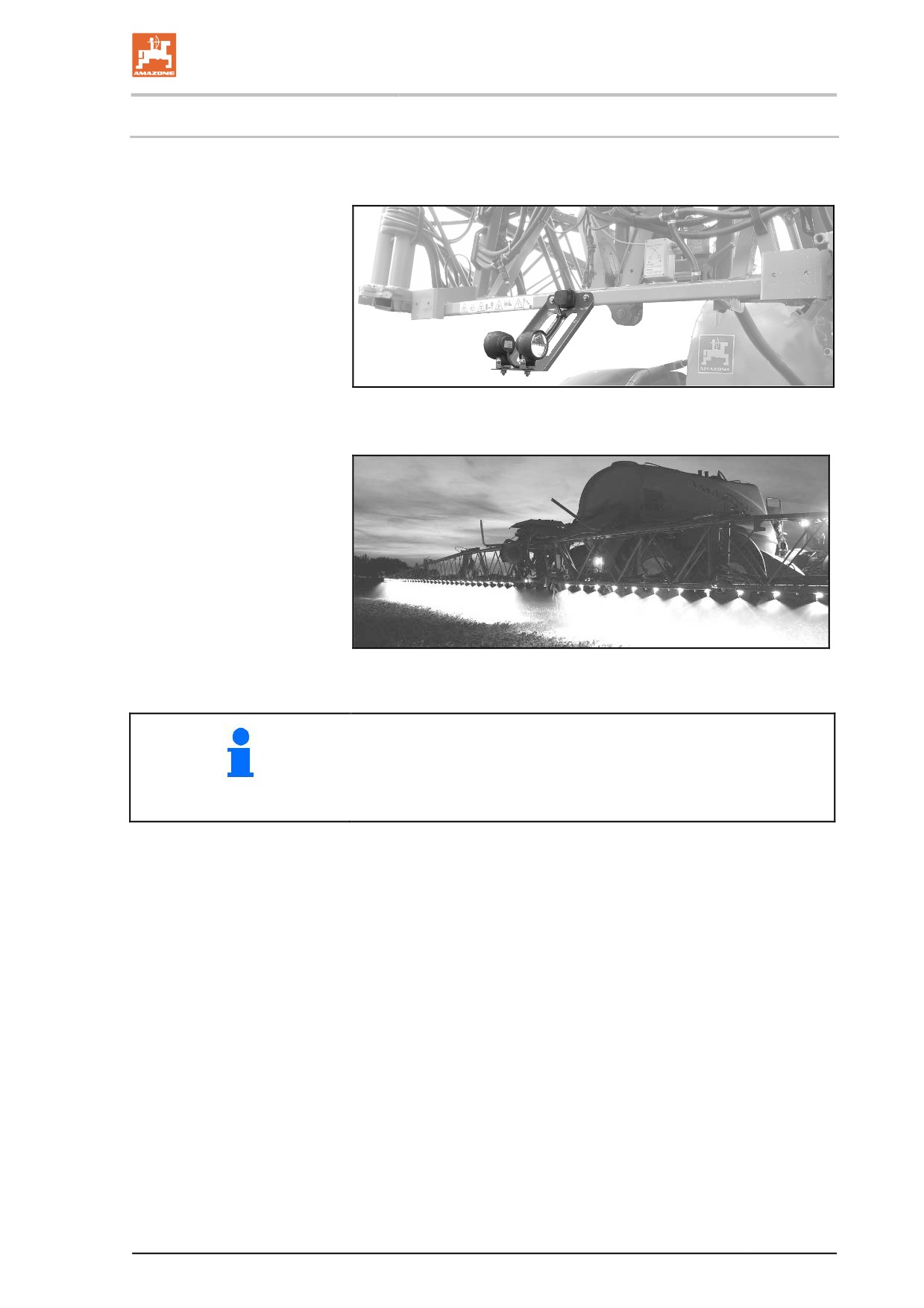
2 work floodlights on the sprayer boom and 2 work floodlights
on the platform.
Fig. 70
LED individual nozzle illumination:
Fig. 71
2 variants:
•
Separate power supply from the tractor is required, operation via
the dashboard.
•
Power supply and operation via ISOBUS.
93
Construction and function of the basic machine
5.25
Comfort equipment
Comfort equipment for machines with
AMATRON+.
Comfort equipment functions:
•
Cleaning - remote-controlled residue
dilution and internal cleaning when inter-
rupting or stopping spraying, without
leaving the tractor.
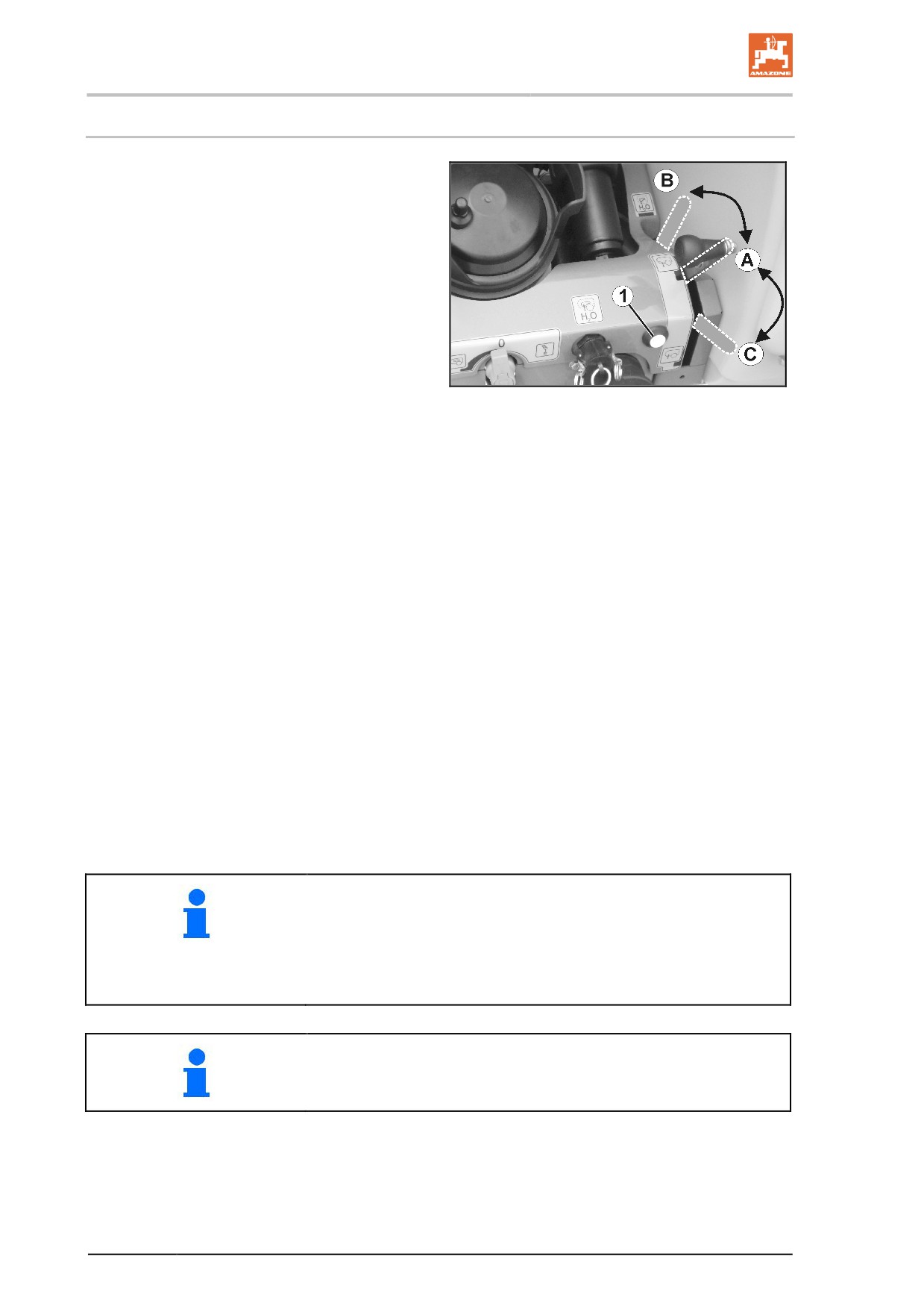
ο Remote-controlled changing from
spraying position (Fig. 73/A) to flushing
position (Fig. 73/B).
ο Cut-off of main and additional agitator.
Fig. 72
ο Remote-controlled switching on and off
of internal cleaning.
•
Automatic agitator - remote-controlled
operation and regulation of the agitating
intensity.
ο Automatic fill-level dependent regula-
tion of the main agitator (agitator tap
missing from control terminal).
ο level falls below 5 %
ο Manual setting of the agitating intensity
on the control terminal.
•
Filling stop when filling via suction port.
ο Filling stopped automatically when the
desired fill level is reached.
ο Filling stopped manually.
Change from filling position (Fig. 73/C)
to spraying position (Fig. 73/A) via op-
erating terminal or on control terminal
(Fig. 73/1).
To change over the suction chest using the button
•
from spraying to flushing, the operating terminal must be in the
work menu,
•
from filling to spraying, the operating terminal must be in the
filling menu
See operating manual for software ISOBUS.
94
Construction and function of the basic machine
5.26
Operating terminal
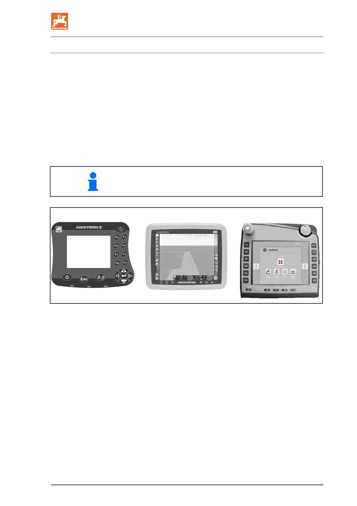
The operating terminal permits:
•
input of machine-specific data.
•
entering the job-related data.
•
controlling the field sprayer to change the spray rate used in
spraying operation.
•
the operation of all functions on the sprayer boom.
•
activating special functions.
•
monitoring the field sprayer during the spraying operation.
The control terminal controls a job computer. Here, the job computer
receives all necessary information and manages the area-based
regulation of the spray rate [l/ha] depending on the quantity (target
quantity) entered and the current operational speed [km/h].
See operating manual for software ISOBUS.
AMATRON 3
AMAPAD
CCI
Fig. 73
95

Construction and function of the basic machine
5.27
AmaPilot / AmaPilot+ multi-function stick
All of the implement functions can be performed
using the AmaPilot and AmaPilot+.
•
AmaPilot with fixed key assignment
•
AmaPilot+ is an AUX-N control element with
freely assignable key assignment (keys pre-
assigned like for the AmaPilot)
30 functions can be selected by pressing with
your thumb. Two additional levels can also be
switched on.
96
Construction and function of the sprayer boom
6
Construction and function of the sprayer boom
The proper condition of the sprayer boom and how it is suspended
have considerable influence on the distribution accuracy of the spray
liquid. With the spraying height of the sprayer boom to the crop set
correctly, a complete overlap is achieved. Nozzles are attached to the
boom at intervals of 50 cm.
Profi-folding:
The boom is operated via the operating terminal.
→ During use, locate tractor control unit red.
See operating manual for software ISOBUS.
Profi-folding consists of the following functions:
•
Folding the sprayer boom in and out,
•
Hydraulic height adjustment,
•
Hydraulic tilt adjustment,
•
Folding in one side of the sprayer boom
•
One-sided, independent raising and lowering of the sprayer
boom / boom extension (Profi-folding II only).
Adjust spraying height
WARNING
Risk of crushing and impact for personnel who are caught while
the height of the sprayer boom is being raised or lowered.
Direct people out of the danger area of the machine before raising or
lowering the sprayer boom using height adjustment.
Always align the sprayer boom parallel to the ground; only then can
the specified spraying height be achieved on all nozzles.
97
Construction and function of the sprayer boom
Folding out and in
CAUTION
It is prohibited to fold the sprayer boom in and out during travel.
DANGER
Always maintain an adequate distance from overhead cables when
folding the sprayer boom out and in. Contact with overhead cables
may lead to fatal injuries.
WARNING
Risk of crushing the entire body and impact due to personnel
becoming trapped by laterally-swivelling machine parts.
These dangers can cause extremely serious and potentially fatal
injuries.
Maintain an adequate safety distance from moving machine parts
while the tractor engine is running.
Ensure that all personnel maintain an adequate safety distance from
moving machine parts.
Instruct personnel to leave the swivel range of any moving machine
parts before swivelling the parts.
WARNING
Danger for third parties from crushing, being drawn in and/or
caught by the moving parts of the boom or impact if they stand
in the swivel range of the boom while it is folding out or in.
•
Instruct personnel to leave the swivel range of the boom before
you fold the boom out or in.
•
Release the control for folding the boom out and in immediately
if someone enters the swivel range.
The hydraulic cylinders for boom folding maintain their respective end
positions (transport position and working position) in both the folded-in
and folded-out boom state.
98
Construction and function of the sprayer boom
Swing compensation
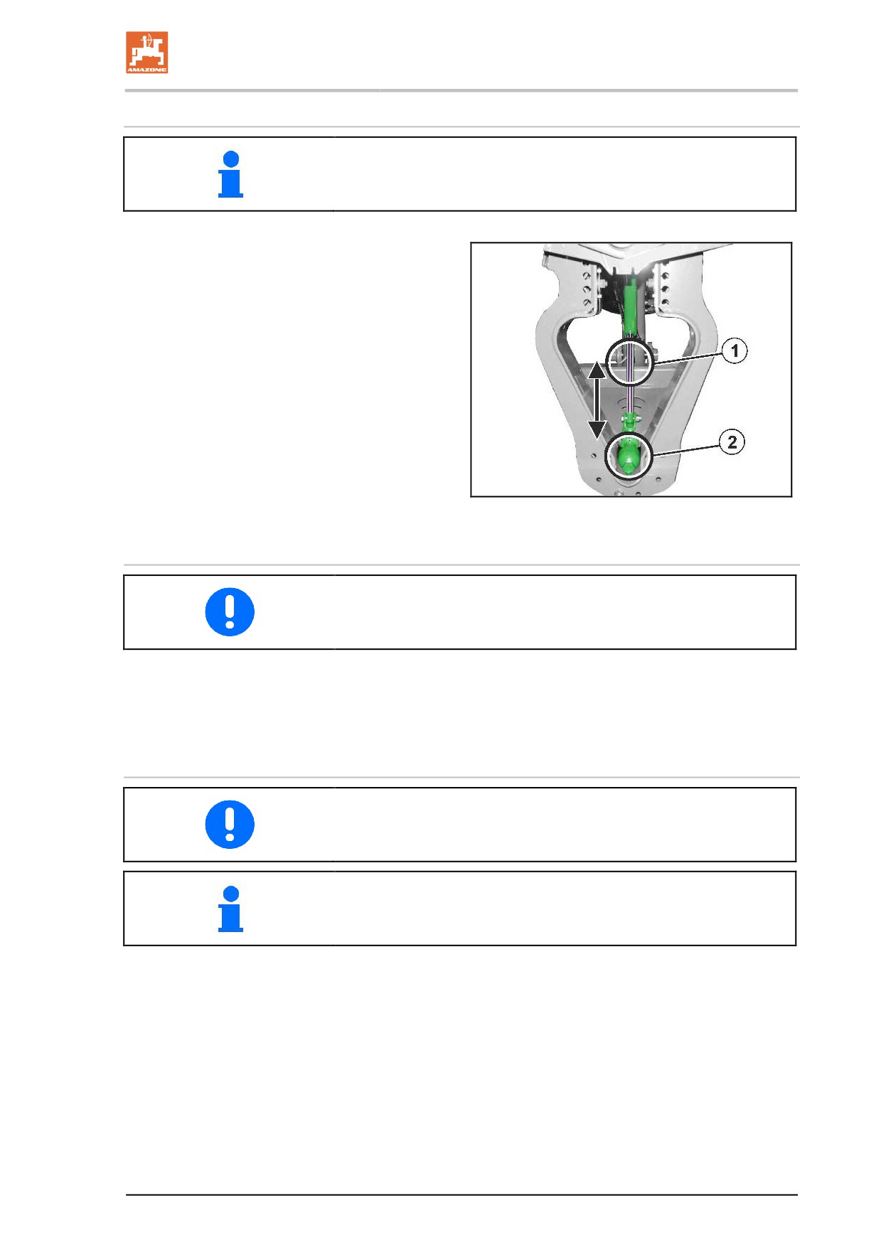
The operating terminal shows when swing compensation (Fig. 76/1) is
locked.
Fig. 76/…
(1) Swing compensation unlocked.
(2) Swing compensation locked.
For illustration purposes, in this image the pro-
tective device has been removed from the swing
compensation.
Fig. 74
Unlocking the swing compensation:
Even lateral distribution can only be achieved with the swing compen-
sation unlocked.
After the sprayer boom is fully folded out, actuate the operating lever
for another 5 seconds.
→ The swing compensation (Fig. 76/1) unlocks and the unfolded
sprayer boom can swing free opposite the boom frame.
Locking the swing compensation:
ο For road transport
ο When folding the boom out and in.
Folding via the tractor control unit: the swing compensation locks au-
tomatically before the boom folds in.
99
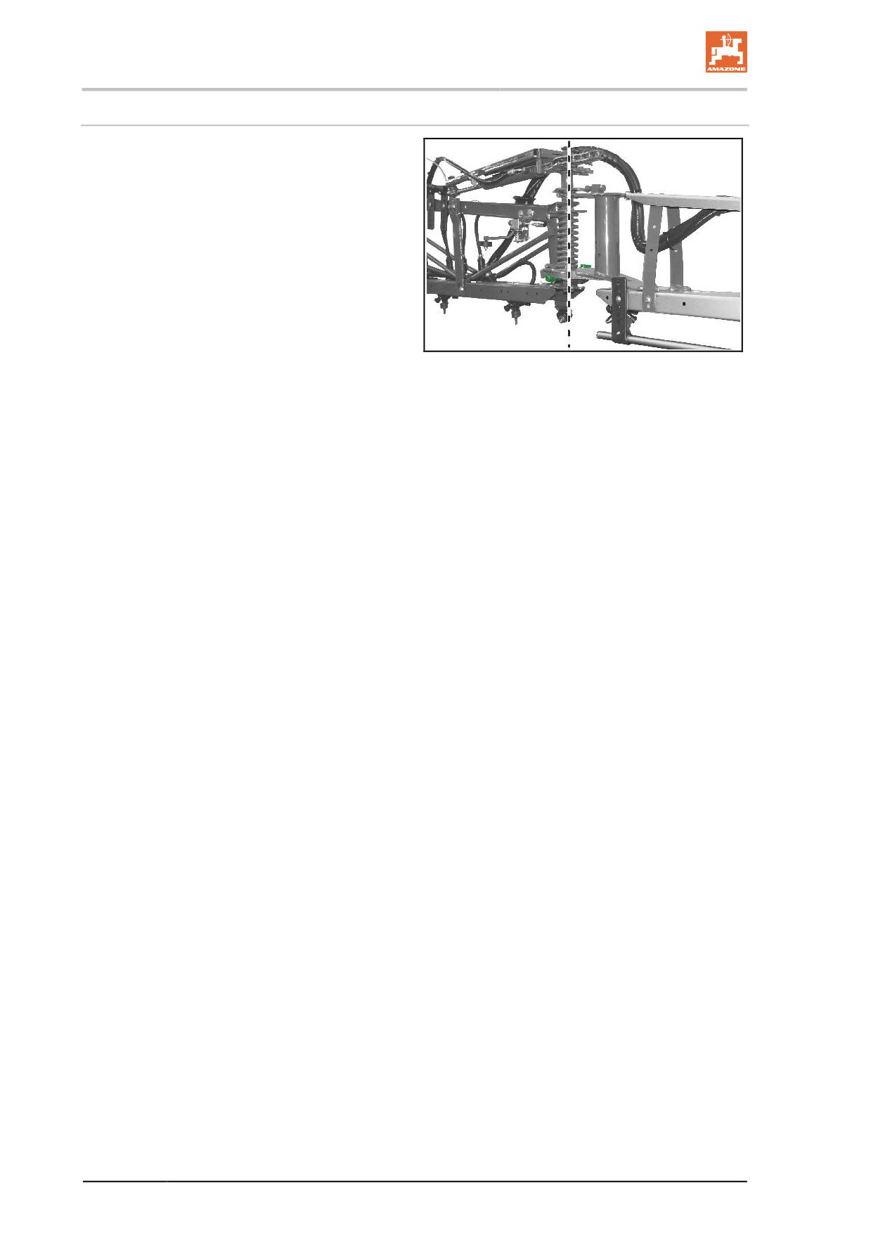
Construction and function of the sprayer boom
Outer boom locking
The outer boom locking mechanisms protect the
boom from damage if the outer boom sections
come into contact with solid obstructions. The
locking mechanism enables the outer boom sec-
tion to avoid collision by moving around the ar-
ticulated axle in and against the direction of trav-
el; it is then automatically returned to its working
position.
Fig. 75
100
Construction and function of the sprayer boom
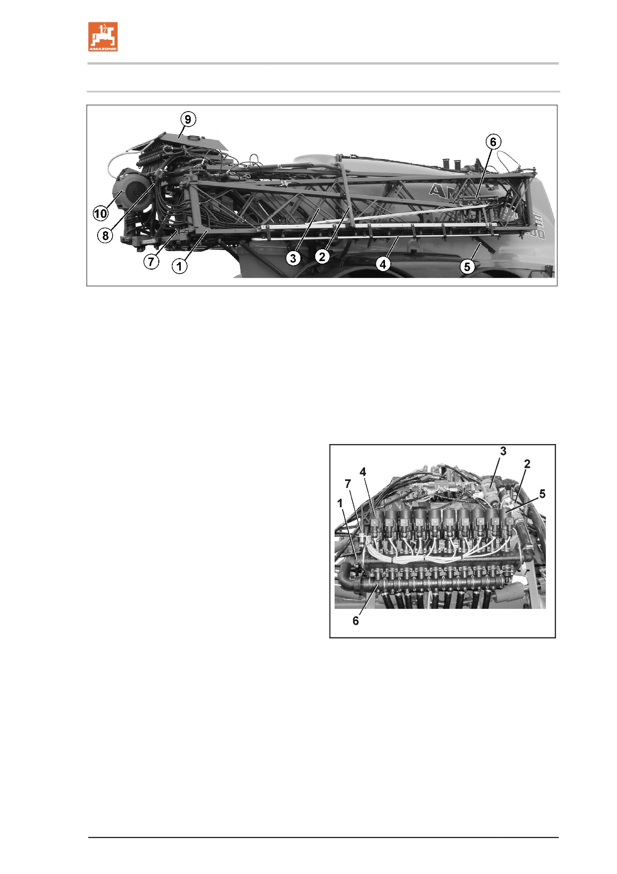
6.1
Super-L boom
Fig. 76
Fig. 78/...
(4) Nozzle protection tube
(1) Sprayer boom with spray lines
(5) Spacer
(2) Transport safety bow
(6) Outer boom locking, see Seite 100
The transport safety bow is used to lock the
(7) Swing compensation, see page 99
folded-in sprayer boom in the transport po-
sition to prevent unintentional folding out
(8) Valve and switch tap for DUS system
(3) Parallelogram frame for adjusting the height
(9) Boom equipment, see Fig. 79
of the sprayer boom
(10) External cleaning device
Fig. 79/...
(1) Pressure connection for the spraying-
pressure pressure gauge
(2) Flow meter for determining the spray rate
[l/ha]
(3) Return flow meter for determining the spray
liquid that has been fed back into the spray
liquid tank
(4) Motor valves for switching the boom part
width sections on and off
(5) Bypass valve
(6) Pressure relief
(7) Pressure sensor
Fig. 77
101
Construction and function of the sprayer boom
6.1.1
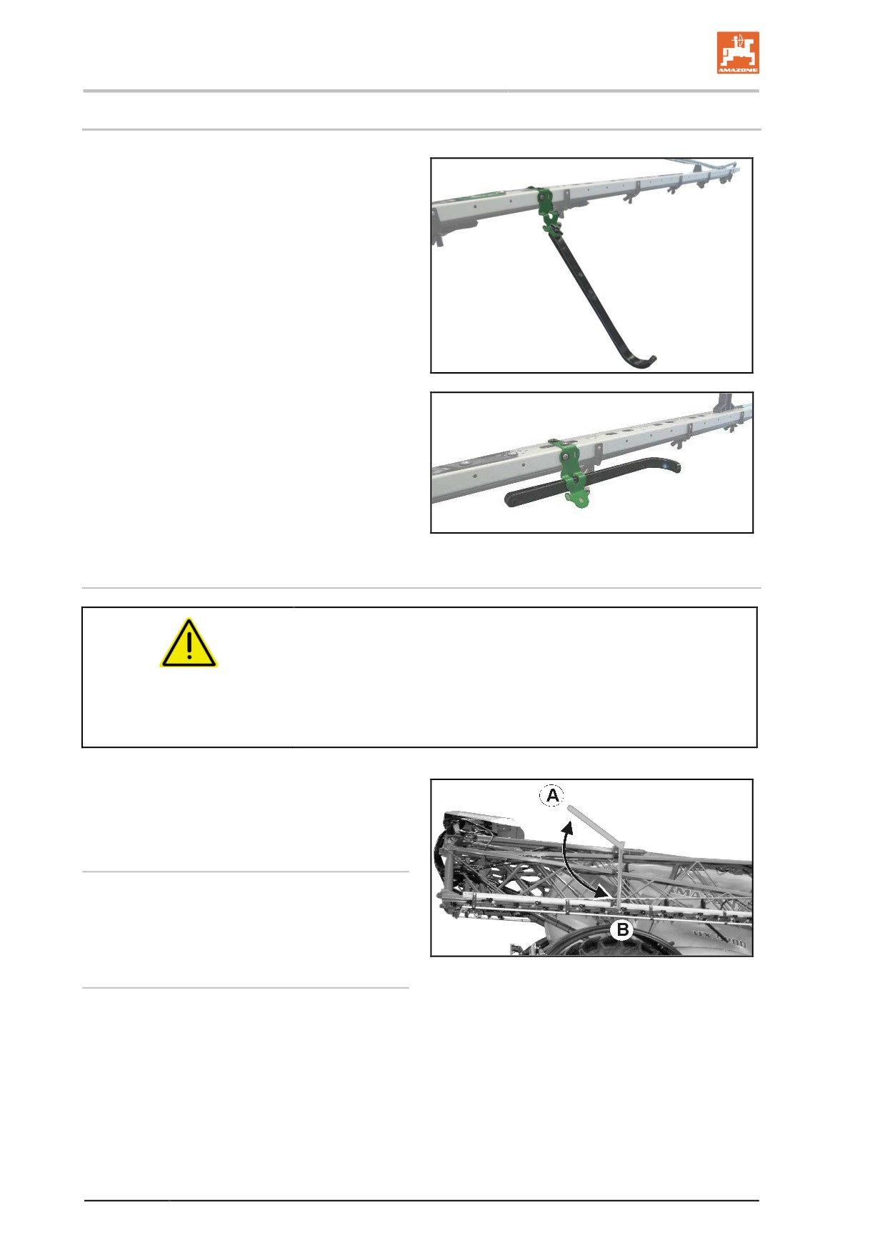
Spacer
The spacer prevents collisions of the boom with
the ground.
When using certain nozzles, the spacers are
within the spray cone.
In this case, attach the spacers horizontally on
the carrier.
Use thumb bolts.
Unlocking and locking the transport safety catch
WARNING
Risk of crushing and impact for other road users if the boom
accidentally unfolds from the transport position during road
transport.
Lock the folded boom package in the transport position using the
transport safety catch before undertaking road transport.
The transport safety bows are for securing the
folded sprayer boom against accidental unfolding
while in transport position.
Unlocking the transport safety catch
Before unfolding the sprayer boom, swivel the
transport safety bows upwards, thereby unlock-
ing the sprayer boom (Fig. 80/A).
Locking the transport safety catch
Fig. 78
After folding the sprayer boom, swivel the
transport safety bows downwards, thereby lock-
ing the sprayer boom (Fig. 80/B).
102
Construction and function of the sprayer boom
6.2
Working with the sprayer boom folded out on one side
Working with the sprayer boom only folded out on one side is only
permissible
•
with the swing compensation locked.
•
briefly for passing obstacles (trees, electricity pylons, etc.).
•
Lock the swing compensation before folding/unfolding the
sprayer boom on one side.
If the swing compensation is not locked, the sprayer boom may
swing off to one side. If the unfolded boom extension strikes the
ground, this can cause damage to the sprayer boom.
•
Use a significantly reduced speed for spraying operation to avoid
the sprayer boom swinging out and coming into contact with the
ground with the swing compensation locked. Unless the sprayer
boom is guided smoothly, even lateral distribution cannot be
guaranteed.
The sprayer boom is fully unfolded.
1. Lock the swing compensation.
2. Using the height adjustment, lift the sprayer boom to a medium
height.
3. Fold up the desired boom extension.
WARNING
After folding, the boom extension swivels forwards into the
transport position.
→ Interrupt the folding process in good time for one-sided spraying.
4. Align the sprayer boom using tilt adjustment so it is parallel to
the target surface.
5. Set the spraying height for the sprayer boom such that the
sprayer boom is a minimum of 1 m off the ground.
6. Switch off the part width sections of the folded-in boom.
7. During spraying operation, drive at a significantly reduced
speed.
103