HAMILTON-T1. Operator's Manual (2022) - page 6
10 Ventilation settings and functions
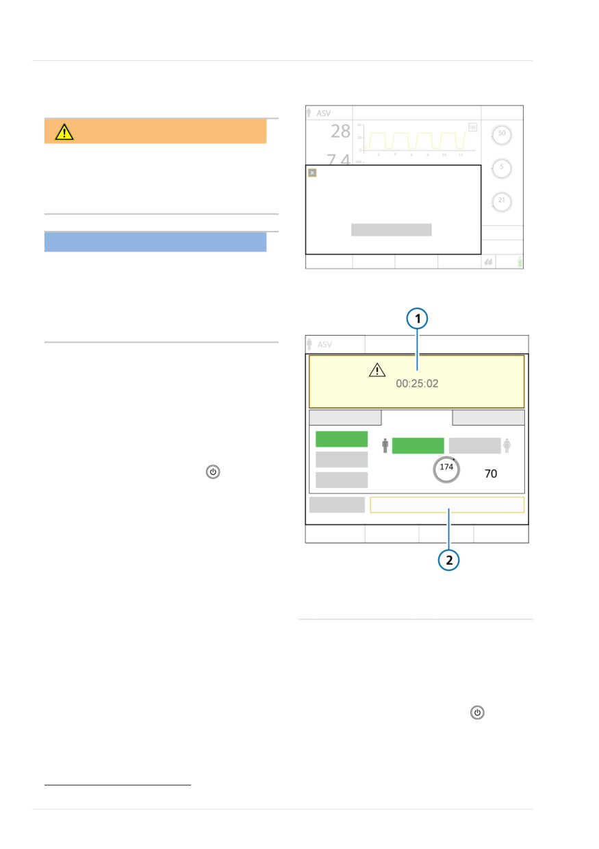
Figure 10-3. Activate Standby window
10.3 Entering/exiting Standby
WARNING
When in Standby, the ventilator does not
automatically resume ventilation when
Standby
the patient is reconnected. You must
No ventilation delivered to the patient.
manually restart ventilation.
Deactivate humidifier during Standby.
Activate standby
NOTICE
• Patient alarms are suppressed in
Standby.
Figure 10-4. Standby window
• Acoustic patient alarms are sup-
pressed for 1 minute after starting
ventilation from Standby.
Standby is a waiting mode that lets you
maintain ventilator settings while the
ventilator is not performing any ventilatory
functions.
To stop ventilation and place the ventilator
in Standby
1. Press and quickly release
(Power/
Standby) while the ventilator is turned
on (Figure 10-2).
The Activate Standby window opens
(Figure 10-3).
2. Touch Activate standby.
The Standby window opens (Figure
69
1
Elapsed time in
2
Start ventilation
10-4).
Standby
While in Standby, the window shows the
elapsed time the ventilator has been in
To end Standby and start ventilation
Standby.
4 Do either of the following:
Note that, if another window is open on
- Touch Start ventilation69.
the display, the elapsed time appears in a
small yellow box on the left side of the
- Press and quickly release
Standby window.
Ventilation resumes with the previous
settings.
69 When HiFlowO2 is selected: Start therapy; when CPR ventilation is on: Start CPR.
216
English | 10103179/02 USA
Oxygen enrichment
10
To stop O2 enrichment manually
10.4 Oxygen enrichment
4 Do either of the following:
NOTICE
- Press
• Oxygen alarms are suppressed while
Ventilation resumes at the previous
O2 enrichment is active.
operator-set oxygen concentration.
• O2 enrichment is not available when
- Change the O2 concentration using
using low-pressure oxygen.
the Oxygen control.
• The Disconnection on patient side
Ventilation resumes at the set oxygen
alarm is suppressed while O2 enrich-
concentration.
ment is active.
Oxygen enrichment is useful before or
10.4.1 Performing an open-suctioning
after tracheal/endotracheal suctioning or
maneuver
for other clinical applications.
The device delivers the following oxygen
CAUTION
concentration for 2 minutes depending on
the selected patient group:
Air leaks may compromise the ventila-
tor's ability to detect a reconnection of
- Adult/Ped. 100% oxygen
the patient after the open-suctioning
- Neonatal. 125% of the current Oxygen
maneuver, resulting in no ventilation
setting
being delivered for the remaining suc-
tioning period (up to 60 seconds). In
To start oxygen enrichment
such cases, stop the maneuver manually,
as described in the following procedure.
4 Press
(O2 enrichment) (Figure
10-2).
NOTICE
After a short time, the ventilator starts
delivering increased oxygen (see
• The Suctioning tool is only available if
above).
the option is enabled on your device.
• Suctioning may affect measured
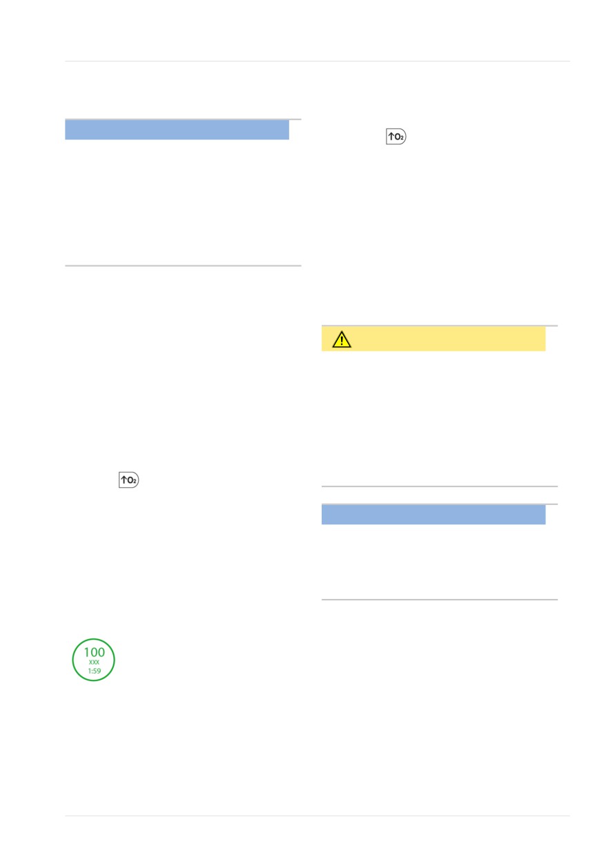
When active, the indicator light next to
values.
the key is green. The Oxygen control turns
green and displays the currently applied
The Suctioning tool is intended to protect
concentration, with a countdown timer.
the operator from possible contamination,
as well as ensure the patient's safety
during an open-suctioning maneuver. The
Suctioning tool stops ventilation when a
patient disconnection is detected by the
When finished, the ventilator resets the
ventilator.
concentration to the previous operator-set
value.
Hamilton Medical | HAMILTON-T1 Operator's Manual
217
10 Ventilation settings and functions
Suctioning is disabled when using:
10.4.2 About closed-suctioning
maneuvers
• HiFlowO2
• NIV or NIV-ST modes
NOTICE
• LPO
• When performing a closed-suctioning
maneuver, follow your institution's
• During neonatal ventilation
protocols.
To perform an open suctioning maneuver
• Ensure O2 enrichment is not active
when performing the closed-suction-
1. Press
(O2 enrichment) for pre-
ing maneuver.
oxygenation.
2. Disconnect the patient.
Verify alarm limit settings and consider
whether O2 enrichment should be used
The text Suctioning maneuver is
prior to performing a closed-suctioning
displayed in the message bar.
maneuver.
Disconnecting the patient stops venti-
lation so that no gases are blown
If the Suctioning tool is enabled on your
through the breathing circuit. All
device, ensure O2 enrichment is not active
alarms are suppressed for one minute.
when performing the closed-suctioning
maneuver.
3. Use a suctioning catheter (not
included) to suction all secretions out
When performing a closed-suctioning
of the patient’s airway.
maneuver, ventilation continues and the
4. Reconnect the patient to the ventila-
current settings do not need to be adjust-
tor.
ed.
Ventilation resumes, post-oxygenation
You can perform a closed-suctioning
starts, and all acoustic alarms are again
maneuver with the following pressure-
suppressed for one minute. Alarm mes-
controlled ventilation modes: APVcmv,
sages and the alarm lamp are still active.
APVsimv, PCV+, PSIMV+, DuoPAP, APRV,
SPONT, or ASV.
To stop the maneuver manually
4 Press
again.
218
English | 10103179/02 USA
High flow oxygen therapy
10
10.5 High flow oxygen therapy
Pressure is measured at the ventilator's
pressure release valve. If pressure exceeds
the high pressure limit of 50 cmH2O, the
WARNING
flow stops and the Check for blockage
alarm is generated. Flow resumes shortly
• Excessive high flows through the
after the pressure is released.
nasal cannula could lead to adverse
clinical events such as barotrauma or
Note that during HiFlowO2, disconnection
pneumothorax.
and apnea alarms are inactive.
• Do not use high flow oxygen therapy
during intrahospital transport.
10.5.1 Working with high flow
• HiFlowO2 is not available when using
oxygen therapy
low-pressure oxygen (LPO).
You must be in Standby to select
HiFlowO2.
NOTICE
To deliver HiFlowO2
Be sure to use the appropriate cannula
size for the patient. For details, see the
1. Place the ventilator into Standby.
cannula Instructions for use.
2. Touch Modes.
3. Touch HiFlowO2, then touch Confirm.
High flow oxygen therapy (HiFlowO2) con-
tinuously delivers an air/gas mixture to the
The Controls window opens. Be sure
patient and monitors the delivered oxygen
to read the safety information.
concentration.
4. Set the desired values for Oxygen and
HiFlowO2 is indicated for adult, pediatric,
Flow, then touch Confirm.
infant, and neonatal patients who can
You can change these settings any-
breathe spontaneously. HiFlowO2 is not
time.
intended to be life-supporting.
5. Touch Start therapy.
The operator sets the oxygen concentra-
The HiFlowO2 Trend graphs and plethys-
tion and flow rate. The set flow can vary
mogram (if SpO2 is enabled) are displayed.
from 2 to 60 l/min for adult and pediatric
patients, and 2 to 15 l/min for neonatal
patients.
When using HiFlowO2, the following para-
meters are monitored: Oxygen and Flow (in
trend and as an MMP), as well as SpO2, if
enabled. If a flow sensor is connected,
Pprox is monitored.
Hamilton Medical | HAMILTON-T1 Operator's Manual
219

10 Ventilation settings and functions
10.6 Manual breath
10.7 Working with a nebulizer
You can prolong inspiration as well as
The ventilator supports the use of
deliver a manually triggered breath.
Aerogen and pneumatic nebulizers for
adult and pediatric patients.70
When active, the indicator light next to
the Manual breath key is green.
For neonatal patients, use an Aerogen
nebulizer system.71
Note that manual breath is disabled
during HiFlowO2.
For connection, positioning, and use
details, see the Nebulizer Positioning
To deliver a manual breath
Guidelines (ELO2020-124-TW) available
on MyHamilton, as well as the manufac-
4 Press and release
(Manual breath)
turer's Instructions for use.
during exhalation (Figure 10-2).
The manual breath uses the mandatory
10.7.1 Working with a pneumatic
breath settings (standard or operator set).
nebulizer
If you try to initiate a manual breath
Before proceeding, review the safety
during the early stage of inspiration or the
information in Chapter 1.
early stage of exhalation, the breath will
not be delivered.
Nebulization with a pneumatic nebulizer is
available in most ventilation modes (not
To deliver a prolonged inspiration
available in SIMV/(S)CMV) except during
neonatal ventilation or when using
4 Press and hold
(Manual breath)
HiFlowO2.
during any breath phase.
You can use a standard inline nebulizer for
If the ventilator is in exhalation, the device
delivery of prescribed medications in the
applies a minimum exhalation phase and
ventilator circuit. The ventilator provides a
then switches to inspiration. The device
stable pressure source to power a pneu-
maintains the inspiration pressure until
matic nebulizer connected to the Nebulizer
you release the key, or for a maximum of
port, optimally specified for a flow of
15 seconds.
approximately 8 l/min.
The ventilator automatically compensates
the additional volume provided by the
pneumatic nebulizer to deliver the set tidal
volume.
For effective nebulization, use a pneu-
matic nebulizer jar.
70 See the Hamilton Medical e-catalog for compatible devices.
71 Aerogen nebulization is not supported for patients younger than 28 days old in the USA.
220
English | 10103179/02 USA

Working with a speaking valve
10
For additional information about nebulizer
10.8.1 Mode changes that automati-
use, including adding medication, refer to
cally turn off compatibility
the manufacturer's Instructions for use.
The following actions automatically deacti-
For connection and setup details, see
vate speaking valve compatibility:
Section 4.6.
• Entering Standby.
To start and stop nebulization
You must manually reactivate compati-
1. Press
(Nebulizer) (Figure 10-2).
bility when restarting ventilation, if
desired.
When active, the indicator light next
to the key is green.
• Selecting a mode that does not support
The fixed nebulizer flow, using 100%
use of a speaking valve.
O2, is synchronized with the inspira-
• Entering CPR mode, Safety ventilation or
tory phase of each breath for
Ambient mode.
30 minutes.
2. To stop nebulization at any time, press
Note that upon automatic deactivation,
the message SpeakValve OFF appears in
again.
the ventilator message bar72. See Table
10-1.
10.8 Working with a speaking
valve
10.8.2 Speaking valve-related control
settings
Speaking valve compatibility is an option
available for Adult/Ped invasive ventilation
In PSIMV+ and SPONT modes, the control
when using any of the following modes:
setting TI max is available in the Controls >
PCV+, PSIMV+, and SPONT.
More window when speaking valve
compatibility is activated (ON).
For details about connecting a speaking
valve, as well as activating the use of a
When speaking valve compatibility is deac-
speaking valve with the ventilator, see
tivated (OFF), TI max is unavailable in these
Section 4.7.
modes unless configured otherwise
(Section 13.4.4).
When a speaking valve is connected to a
patient, remove the speaking valve before
activating CPR ventilation.
Speakvalve is not accessible during CPR.
72 Except in Safety ventilation or Ambient mode.
Hamilton Medical | HAMILTON-T1 Operator's Manual
221
10 Ventilation settings and functions
10.8.3 Parameters monitored when
10.8.4 Speaking valve-related alarms
compatibility is activated
The alarms listed in the table below are
When speaking valve compatibility is acti-
related to speaking valve compatibility. For
vated, the following parameter changes
help resolving alarm situations, see Table
are in effect:
9-2.
•
The following monitoring parameters
Table 10-1. Speaking valve-related alarm condi-
are invalid and show dashes (---):
tions
AutoPEEP
PTP
Alarm
Status
Cstat
RCexp
SpeakValve ON
Exp Flow
Rinsp
SpeakValve ON
Always displayed as long
Low priority
as compatibility is acti-
ExpMinVol
VLeak
vated.
MVLeak
VTE
Vt low
When SpeakValve is ON,
P0.1
VTESpont
this alarm is based on
High priority
when speaking
delivered volume instead
Pmean
Vt/IBW
valve compatibi-
of exhaled volume. VTI
Pplateau
lity (SpeakValve)
was below the limit for 2
consecutive breaths.
is activated
This alarm can indicate
•
If VTE is set as a main monitoring para-
that the cuff is still
meter (MMP), VTI is displayed instead.
inflated!
If both VTI and VTE are selected as
Be sure to also carefully
MMPs, upon activation, the VTE value
check the alarm and
shows dashes (---).
ventilator settings.
•
Apnea backup ventilation is disabled.
Check patient
Generated when the Vt
interface
low or Low pressure alarm
Once compatibility is deactivated, Apnea
is active.
backup ventilation returns to its previous
High priority
setting, and the parameters listed above,
Check for:
including VTE, are again actively moni-
• Disconnection
tored.
• Whether cuff is fully
deflated
• Upper airway occlusion
• Speaking valve is oper-
ating properly
222
English | 10103179/02 USA
CPR ventilation
10
Alarm
Status
10.9 CPR ventilation
ExpMinVol low
Automatically set to OFF.
The HAMILTON-T1 uses CPR ventilation to
ExpMinVol high
continue respiration during the adminis-
tration of cardiopulmonary resuscitation.
Disconnection
Suppressed. If the lower
When activated, CPR ventilation adjusts
on patient side
Pressure limit is appropri-
the ventilator to:
Disconnection
ately set, when a discon-
nection occurs, a Low
• Use either APVcmv or PCV+ ventilation
on ventilator
pressure alarm is genera-
mode
side
ted.
• Display relevant MMPs, waveforms, and
Inspiratory
Suppressed.
a CPR duration timer
volume limita-
• Modify the alarm limits while CPR venti-
tion
lation is in use (see Table 10-4)
SpeakValve OFF (after being enabled)
CPR ventilation is indicated for adult, pedi-
Volume related,
Upon deactivation, all
atric, and neonatal patients.
including low
volume-related alarm
CPR ventilation is available during all venti-
and high
limits are reset based on
ExpMinVol limits
the patient's IBW.
lation modes except for nCPAP, nCPAP-PC,
and when using HiFlowO2 therapy.
SpeakValve OFF
Displayed when compati-
bility has been automati-
Table 10-2 provides an overview of work-
Low priority
cally deactivated.
ing with CPR.
Confirm the change in
Table 10-2. CPR ventilation overview
status by pressing the
Audio pause key.
For details about ...
See ...
Configuring a default
Section 13.8
mode
Starting and stopping CPR Section 10.9.2
ventilation
Working with CPR ventila- Section 10.9.2
tion
CPR-related control
Section 10.9.1
settings
Monitoring and display
Section 10.9.3
when CPR ventilation is
on
CPR-related alarms
Section 10.9.4
Hamilton Medical | HAMILTON-T1 Operator's Manual
223
10 Ventilation settings and functions
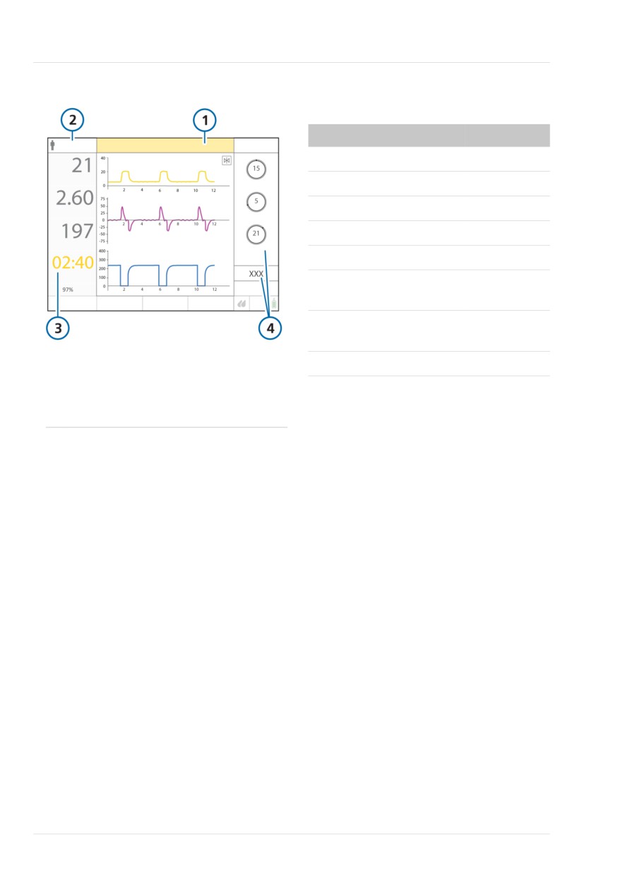
Figure 10-5. CPR ventilation on
Table 10-3. CPR ventilation mode controls and
default settings
Parameter
Default
CPR/PCV+
CPR ON
Rate (b/min)
10
I:E
1:5
PEEP/CPAP (cmH2O)
5
Plimit (cmH2O)
45
Oxygen (%)
100
Vt/IBW (ml/kg)
6
SpO2
(only in APVcmv)
ΔPcontrol (cmH2O)
15
(only in PCV+)
1
CPR ON alarm
3
CPR timer
Apnea time (s)
10
2
Active ventilation
4
Controls for the
mode
active ventilation
10.9.2 Working with CPR ventilation
mode
When you start CPR ventilation, the venti-
lator switches to the configured mode and
10.9.1 About the CPR modes and
settings. You can start CPR at any time,
settings
from Standby or during active ventilation.
The ventilator uses one of two modes
Note the following when CPR ventilation is
during CPR ventilation:
on:
• APVcmv (default mode)
• Flow trigger is unavailable and set to
• PCV+
OFF.
• P-ramp is unavailable and set to 50 ms.
You can change the default ventilation
mode to use. For details, see Section 13.8.
• In APVcmv mode, you set the Vt/IBW in
Configuration. This defines the initial
The mode control settings are described in
start-up setting for the tidal volume (Vt)
Table 10-3.
control.
• For neonatal patients, Apnea time is set
to 10 seconds.
• The alarm limits for ExpMinVol, fTotal,
VT, and PetCO2 are set to their maxi-
mum and minimum settings.
• The SpO2 and Pulse alarm limits are set
to OFF, if applicable.
224
English | 10103179/02 USA
Monitoring and display during CPR
10
• The Speaking valve compatibility is
10.9.3 Monitoring and display during
deactivated.
CPR
• The low-priority CPR ON alarm is active.
When CPR ventilation is on, the following
• HAMILTON-H900 humidification
MMPs are displayed: Ppeak, VTE, fTotal,
switches to Invasive mode.
and the CPR Timer.
To start CPR ventilation
In addition to the MMPs, the Paw, PCO273,
and Flow waveforms are displayed. See
1. Touch Modes.
Figure 10-5.
2. In the Modes window, touch CPR.
The Controls > Basic window opens.
10.9.4 CPR-related alarms
3. Review and, if needed, adjust the
The following alarms are related to CPR
control settings, then touch Confirm
ventilation. For help resolving alarm situa-
to start CPR ventilation.
tions, see Table 9-2.
The mode changes to the default CPR
Stopping CPR ventilation or changing the
mode set on the ventilator, and the CPR
ventilation mode resets the alarms to the
ON alarm is generated. Ventilation starts
previous settings.
or continues.
Table 10-4. CPR ventilation-related alarm condi-
To stop CPR ventilation and enter Standby
tions
1. Press the Power/Standby button.
Alarm
Status
2. In the confirmation window, touch
Activate standby.
CPR ON
Always displayed as long
as CPR ventilation is on.
CPR ventilation stops and the device enters
Standby.
Pressure high
As already configured
(Plimit + 10 cmH2O).
To restart CPR ventilation, touch Start CPR.
ExpMinVol low/
The alarm limits are auto-
To stop CPR ventilation and continue venti-
high
matically set to the mini-
lating the patient
mum and maximum
fTotal low/high
1. Touch Modes.
settings.
PetCO2 low/
2. Select and confirm a ventilation mode.
high74
74
Pulse low/high
The ventilator starts ventilation in the
selected mode using the previously
SpO2 low/high74
defined settings.
Vt low/high
CPR ventilation events and elapsed CPR
ventilation time are recorded in the Event
log.
73 Only available if the CO2 communication board is installed and the CO2 sensor is enabled.
74 If the option is installed and activated.
Hamilton Medical | HAMILTON-T1 Operator's Manual
225

10 Ventilation settings and functions
To capture a screenshot of the display
10.10 Locking and unlocking
1.
If the potential equalization USB cable
the touch screen
is in use, remove it from the USB port.
You can lock the touch screen to prevent
inadvertent entries.
2.
Press
(Figure 10-2) when the
desired display is shown.
When screen lock is active:
- If a USB drive is in the ventilator USB
• The indicator light next to the key is lit
port, the device saves the image to
green.
the screenshots folder on the USB
drive.
• Touching the screen generates an audi-
ble beep and the message, Screen is
- If no USB drive is inserted, the device
locked!, is displayed.
saves the image to the ventilator
memory. You can later download the
• Some device controls remain available,
image using the Hamilton Connect
while others are disabled, as follows:
App76.
- Active controls. Audio pause, Manual
The indicator light next to the key is lit
breath, O2 enrichment, Nebulizer, Day/
green while the ventilator saves the
Night75
image.
- Inactive controls. Touch screen,
3.
Reinsert the potential equalization
Power/Standby, Print screen, P&T knob
USB cable into the USB port, if
To lock or unlock the screen
needed. CO2 sensor readings resume
within 20 seconds.
4 Press
(Screen lock/unlock) (Figure
The filename uses the following format:
10-2).
screenshot_T1-sn_yyyy-mm-dd_hh-mm-
ss.jpg
10.11 Capturing a screenshot
where:
Before using a USB drive with the ventila-
T1 is the device name
tor, review the safety information in
sn is the device serial number
Section 1.5.4.
yyyy is the year
mm is the month
The
(Print screen) key saves a JPG file
dd is the date
of the current ventilator display. You can
hh is the hour (in 24-hour format)
save the screenshot to a USB drive or to
mm is the minute
internal ventilator memory.
ss is the second
75 Applies only to devices with serial number > 3000.
76 For details, see the Hamilton Connect App Instructions for use.
226
English | 10103179/02 USA
Setting display options
10
10.12 Setting display options
10.12.2 Day and night display bright-
ness
You can set the day and night display
brightness, as well as the device date and
Use these settings to set the brightness of
time.
the display for use during the day and
night.
10.12.1 Setting date and time
To set the display brightness
You set the date and time for the ventila-
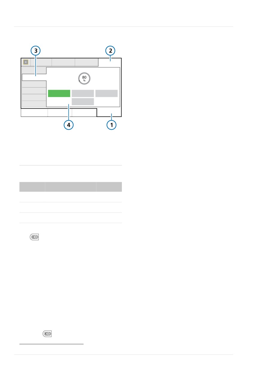
1. Touch System > Settings (Figure 10-7).
tor in the System > Settings window.
2. Touch Day & Night.
Ensure the date and time are set correctly
3. To select Day mode with a bright
so that event log entries have accurate
display, touch the Day button.
time and date stamps.
To select Night mode with a dimmer
To set the date and time
display, touch the Night button.
1. Do either of the following:
4. Adjust the brightness of the display in
each mode using the Brightness
- Touch the Date/Time indicator at the
control. The setting you choose
top of the display (Table 2-3).
becomes the new default for that
- Touch System > Settings > Date &
mode.
Time (Figure 10-6).
5. To have the device control the bright-
2. Adjust the date and time, then touch
ness based on ambient light, touch
Apply to save the changes.
the Automatic button.
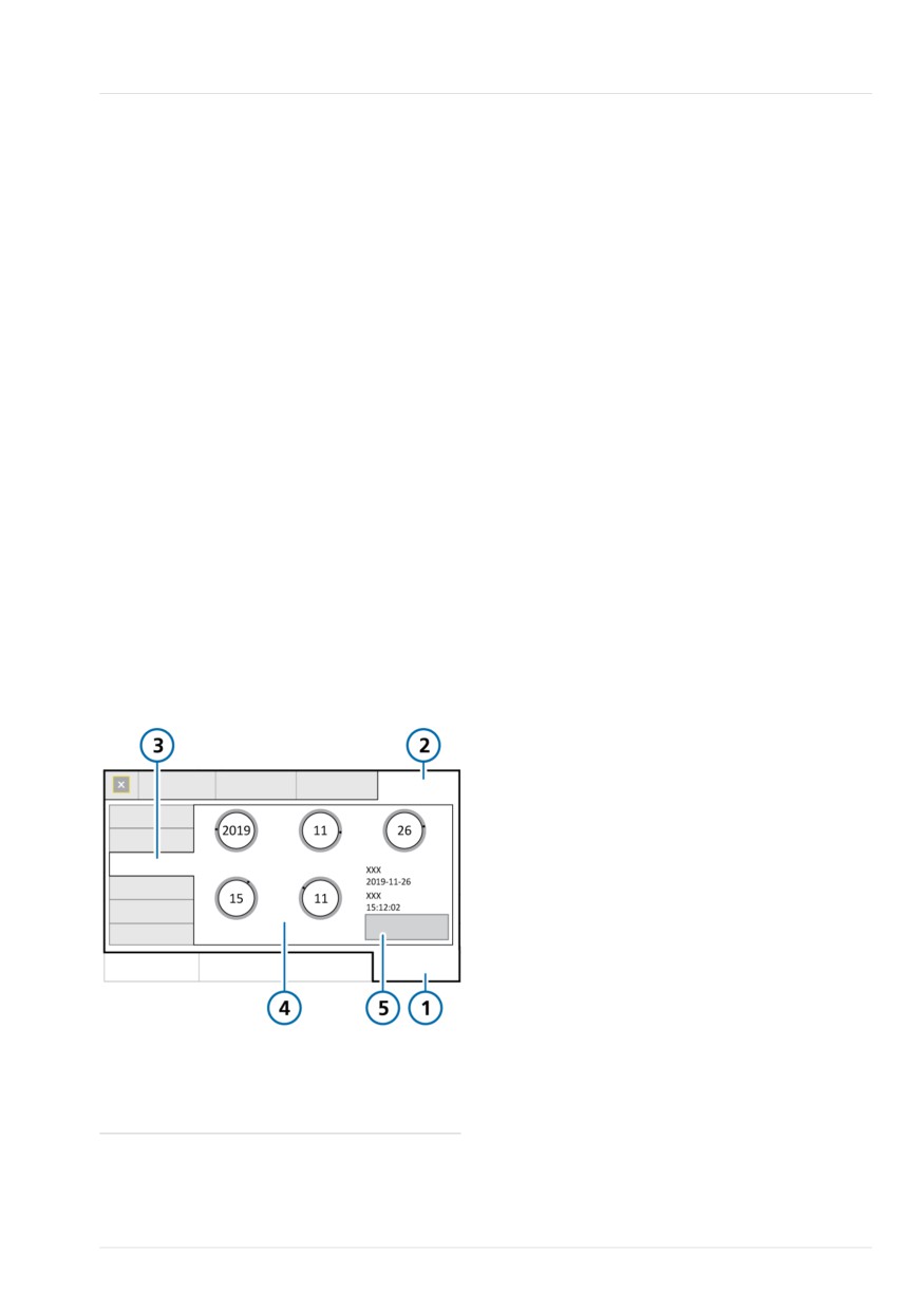
Figure 10-6. Date & Time settings
The device continuously senses the
available light and dynamically adjusts
the display brightness settings.
If the NVG option is installed, you can set
the display brightness for use with night
vision goggles.
To set the display brightness with NVG
1. Touch System > Settings (Figure 10-7).
2. Touch NVG.
The NVG Brightness control is enabled.
3. Adjust the brightness of the display in
NVG using the Brightness control. The
1
System
4
Date and time settings
setting you choose becomes the new
2
Settings
5
Apply
default for the mode.
3
Date & Time
Hamilton Medical | HAMILTON-T1 Operator's Manual
227
10 Ventilation settings and functions
Figure 10-7. Day & Night window
10.13 About the Event log
Once the ventilator is turned on, event
logs collect data about clinically relevant
ventilator activities, including alarms, tech-
nical notes, setting changes, calibrations,
maneuvers, and special functions.
The date, time, and a unique identification
reference (ID) for event classification is
included.
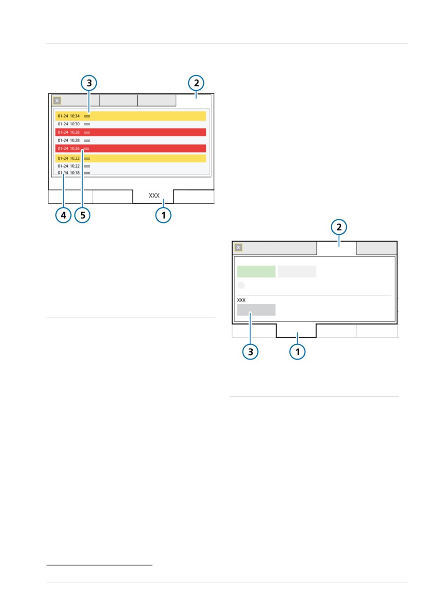
Alarms are shown in color, depending on
priority level (yellow for low or medium,
red for high).
1 System
4 Day, Night, Automatic,
A more extensive log including technical
Brightness settings
and configuration details is available to
2 Settings
5 NVG
service engineers.
3 Day & Night
6 NVG Brightness setting
When setting up a new patient:
Table 10-5. Day and Night settings
• Data is appended to the existing event
log when you select the Last patient
Setting
Brightness range
Default
tab.
Day
10% to 100%
80%
• The event log is cleared and starts
again when you select a different
Night
10% to 100%
40%
patient group tab (Adult/Ped or Neona-
NVG
1 to 10
5
tal).
Event log data persists after shutting off
the ventilator or in the event of a power
The
(Day/Night) key77 allows you to
loss. A maximum of 10,000 events is
quickly switch the display between
stored. When a log buffer is full, new
defined Day and Night settings. When the
events overwrite the oldest log entries.
Night setting is active, the green indicator
light next to the key is lit.
You can copy event log data. See Section
10.13.1.
If the NVG option is installed on the venti-
lator, the Day/Night key switches between
To display the Event log
the Night and NVG settings. When the
NVG setting is active, the green indicator
4 Touch Events.
light next to the key is lit.
To change the display brightness to the
defined Day or Night setting
4 Press
(Figure 10-2).
77 Applies only to devices with serial number > 3000.
228
English | 10103179/02 USA
Copying event log data
10
Figure 10-8. Events window
To copy the log files
1. Place the ventilator into Standby and
insert a USB drive into the USB port
(Figure 2-5).
2. Touch Tools > Utilities (Figure 10-9).
3. Touch Export Logs.
4. Remove the USB drive when the text
Export successful is displayed.
The log files are saved to the folder named
T1-sn<serial number> on the USB drive.
Figure 10-9. Data transfer window
1
Events
4
Informational mes-
sage
2
All
5
High-priority alarm
(red)
3
Low-/medium-
priority alarm
(yellow)
10.13.1 Copying event log data
Before using a USB drive with the ventila-
tor, review the safety information in
1
Tools
3
Export Logs
Section 1.5.4.
2
Utilities
You can copy event and service logs to a
USB drive or download them to your
smartphone using the Hamilton Connect
App78.
The USB drive must have a FAT or FAT32
format and it must not have an operating
system or a security system installed.
78 For details, see the Hamilton Connect App Instructions for use.
Hamilton Medical | HAMILTON-T1 Operator's Manual
229
11
Working with external devices
11.1
Working with the HAMILTON-H900 humidifier
232
11.2
Working with smartphones and clinical networks
242
231
11 Working with external devices
Table 11-1. Operation overview
11.1 Working with the
HAMILTON-H900 humidifier
For details about ...
See ...
Before proceeding, review the safety
Accessing humidifier
Section 11.1.1
information in Chapter 1.
controls on the ventilator
Using the HAMILTON-H900 humidifier
Humidification modes
Section 11.1.2
with the ventilator offers remote access to
Changing humidity using Section 11.1.3
humidifier controls and status directly
temperature controls
from the ventilator display. In addition,
functions between the devices are
Entering Standby
Section 11.1.4
synchronized.
Turning the humidifier
Section 11.1.5
You can control some humidifier functions
on/off
from the ventilator or on the humidifier
Humidifier-related alarms
Section 11.1.6
itself.
Humidifier-related para-
Section 11.1.7
This section describes using the ventilator
meters
to manage and monitor humidifier
settings.
11.1.1 Accessing humidifier controls
For detailed information about the
on the ventilator
settings, specifications, patient set up,
humidifier operation, humidifier configu-
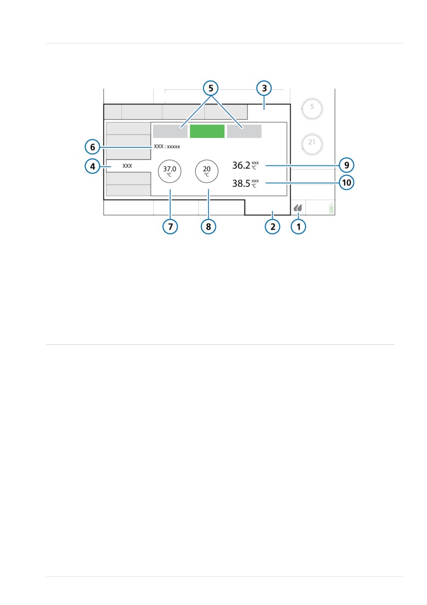
The Humidifier window shows the water
ration, and important safety information,
chamber exit temperature (T humidifier)
see the HAMILTON-H900 Instructions for
and the humidifier Y-piece temperature
use.
(T Y-piece). It also provides access to the
operations listed in Table 11-1.
To open the Humidifier window
4 Do either of the following (Figure
11-1):
- Touch
(Humidifier).
‒ Touch System > Settings > Humidi-
fier.
If communication between the humidifier
and the ventilator is lost, the window is
disabled.
232
English | 10103179/02 USA
Accessing humidifier controls on the ventilator
11
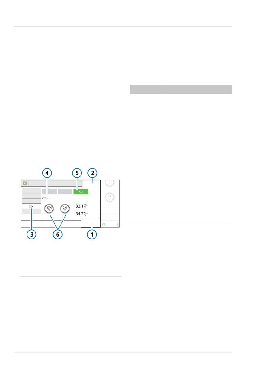
Figure 11-1. System > Settings > Humidifier window
1
Humidifier icon
6
Currently active humidification mode
(Invasive, NIV, HiFlow)
2
System
7
Set temp control
3
Settings
8
T gradient control
4
Humidifier
9
T humidifier
5
Off, Auto, Manual
10
T Y-piece
Hamilton Medical | HAMILTON-T1 Operator's Manual
233

11 Working with external devices
11.1.1.1 About the Humidifier button
Note that the connection status icon on
the humidifier is not displayed when in
The
(Humidifier button) at the bottom
Standby.
right of the display provides quick access
to the Humidifier window and indicates
11.1.2 About the humidification
the state of the humidifier, including
modes
whether any alarms are active.
The humidifier offers three humidification
Table 11-2. Humidifier button icon states
modes: Invasive, NIV, and HiFlow79.
Icon state
Description
The set mode determines the initial tem-
perature settings at the water chamber
Grayed out. Humidifier is not
exit and at the Y-piece, as well as the
connected.
allowed temperature ranges for these
If no icon is displayed, this
settings. The control settings are described
option is not available in your
in Table 11-3.
country.
The Invasive mode allows for a higher
Outline only. Humidifier is con-
temperature range than the NIV mode. For
nected but turned off.
details about the humidifier settings and
ranges, see the HAMILTON-H900 Instruc-
Full, white. Humidifier is con-
tions for use.
nected and turned on.
The currently set humidification mode is
shown in the System > Settings > Humidifier
Yellow. Humidifier is con-
nected and a low- or medium-
window.
priority humidifier alarm is
Figure 11-2 shows the Invasive mode
active.
selected; Figure 11-3 shows the NIV mode
Red. Humidifier is connected
selected.
and a high-priority humidifier
When connected to the ventilator, the
alarm is active.
humidifier automatically matches the
humidification mode to the type of venti-
11.1.1.2 Verifying connection status
lation mode selected on the ventilator. For
example, when the mode on the ventilator
When communication is established
is invasive, such as ASV, the humidifier is
between the humidifier and the ventilator,
automatically set to Invasive mode.80
the active connection status is displayed
on both devices: the Humidifier icon on
the ventilator display (Table 11-2), and the
(Connection to ventilator) symbol on
the humidifier become active.
79 On the ventilator display, the text HiFlowO2 is shown, but on the HAMILTON-H900 humidifier, HiFlow is shown.
80 Supported for HAMILTON-H900 version 1.10x and later. If using an older version of humidifier, when treating the patient using
HiFlowO2 therapy, the humidifier uses the same temperature and humidity specifications as the humidifier's Invasive mode.
234
English | 10103179/02 USA
Auto and Manual control settings
11
Depending on the selected humidification
When set to Auto, the temperature
mode, you can set controls automatically
controls in the System > Settings > Humidi-
or manually:
fier window are disabled. You must first
enable Manual mode to change any
• The humidifier supports invasive and
settings.
noninvasive ventilation modes, as well
as high flow oxygen therapy, for which
In both cases, the humidifier automatically
you can use either automatic (Auto) or
controls the temperatures to reach the
manual settings.
specified settings.
• Any time the humidifier changes from
Automatic settings (Auto)
one mode to another, it also automati-
cally switches to Auto settings and
When set to Auto, the humidifier loads the
loads the configured default settings
associated default settings specified for
for the newly selected humidification
the selected humidifier mode in its confi-
mode.
guration and uses them to control the gas
temperature.
For details about Auto and Manual control
settings, see Section 11.1.2.1.
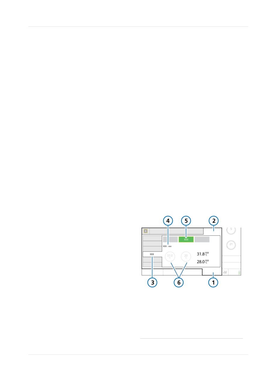
In Auto mode, the temperature controls in
the ventilator System > Settings > Humidi-
Further, the humidifier matches the oper-
fier window are grayed out (disabled), but
ating status of the ventilator. If ventilation
they display the configured Auto settings
is active, the humidifier is running. If the
(Figure 11-2).
ventilator is in Standby, the humidifier
automatically enters Standby.
For details about these settings, see the
HAMILTON-H900 Instructions for use.
Note that if the humidifier is turned off
and the ventilator is still on, starting venti-
Figure 11-2. Auto mode
lation will not automatically start the
humidifier. The humidifier must be turned
on manually. See Section 11.1.5.
11.1.2.1 Auto and Manual control settings
The water chamber exit temperature and
temperature gradient are set using either
of the following methods:
• Loaded from the configured default
settings on the humidifier (Auto mode)
• Set manually by the operator (Manual
1
System
4
Invasive
mode)
2
Settings
5
Auto
3
Humidifier
6
Disabled controls
showing the config-
ured Auto temperature
settings
Hamilton Medical | HAMILTON-T1 Operator's Manual
235
11 Working with external devices
Manual settings
11.1.3 Changing humidity using
When set to Manual, you set controls as
temperature controls
follows:
You can adjust the following controls on
• Invasive, NIV: Set temp, T gradient
either device.
• HiFlow: Set temp
Table 11-3. Adjustable humidifier controls
Table 11-3 describes these controls.
Control
Description
The temperature controls in the ventilator
Set temp
Temperature at the water
System > Settings > Humidifier window are
chamber exit.
enabled (Figure 11-3).
The possible range of values
You can change settings both in the
for this control depends on the
Humidifier window as well as directly on
selected humidifier operating
the humidifier. When you change values
mode: Invasive, noninvasive
on the humidifier, the values are also
(NIV), or HiFlow.
reflected on the controls on the ventilator.
Higher values result in higher
absolute humidity.
Figure 11-3. Manual mode
T gradient
The difference between the
temperature at the water
chamber exit and at the
Y-piece.
A higher value decreases con-
densation.
Can only be changed in Inva-
sive and NIV modes.
In a way, the Set temp and T gradient para-
meters are linked. The maximum allowed
1
System
4
Noninvasive
temperature at the patient (Y-piece) is
2
Settings
5
Manual
42°C. The combination of the values set
for these two parameters cannot exceed
3
Humidifier
6
Available temper-
this limit.
ature controls
For example, if T gradient is set to 2°C, the
highest possible setting for Set temp in the
Invasive mode is 40°C.
Note, however, that the T gradient setting
takes precedence over the Set temp value.
For example, if Set temp is set to 40°C,
you can set T gradient to 3°C even though
236
English | 10103179/02 USA
Entering Standby
11
the combination exceeds 42°C. Once the
To turn off the humidifier from the ventila-
T gradient setting is accepted, the Set temp
tor
value automatically resets to 39°C.
4 In the System > Settings > Humidifier
window, touch the Off button (Figure
To manually specify humidifier settings
11-1).
4 Do either of the following:
The Off button turns green and all of the
- In the System > Settings > Humidifier
controls in the window are disabled.
window on the ventilator, touch the
Manual button, then select the desired
The Auto and Manual buttons remain
Set temp and T gradient values.
available.
- Change the chamber exit tempera-
To turn the humidifier back on from the
ture or temperature gradient directly
ventilator
on the humidifier.
1. In the System > Settings > Humidifier
The changes are applied immediately.
window, touch the Manual or Auto
button to turn on the humidifier
For details about working directly on the
(Figure 11-1).
humidifier, see the HAMILTON-H900
Instructions for use.
2. Check the settings and adjust, if
needed.
11.1.4 Entering Standby
When you start ventilation, the humidifier
starts automatically.
The humidifier automatically enters
Standby mode when the ventilator enters
If the humidifier is turned off and you start
Standby.
ventilation, it will not automatically turn
on.
11.1.5 Turning the humidifier on/off
11.1.6 About humidifier-related
You can turn the humidifier on or off both
alarms
from the ventilator and from the device
itself.
Alarms on the HAMILTON-H900 are
displayed on the ventilator immediately.
When you connect the humidifier to the
Humidifier-related alarm messages are
ventilator, the humidifier assumes the
indicated in the following locations:
same state as the ventilator.
• On the humidifier, graphically
That is, if the ventilator is in Standby, the
• Alarm message on the ventilator main
humidifier is as well. If the ventilator is in
display
active ventilation, the humidifier starts
operation immediately.
• The Humidifier icon changes color
(Table 11-2)
The alarms listed here may not be compre-
hensive. Be sure to review the HAMILTON-
H900 Instructions for use for details and
troubleshooting information.
Hamilton Medical | HAMILTON-T1 Operator's Manual
237
11 Working with external devices
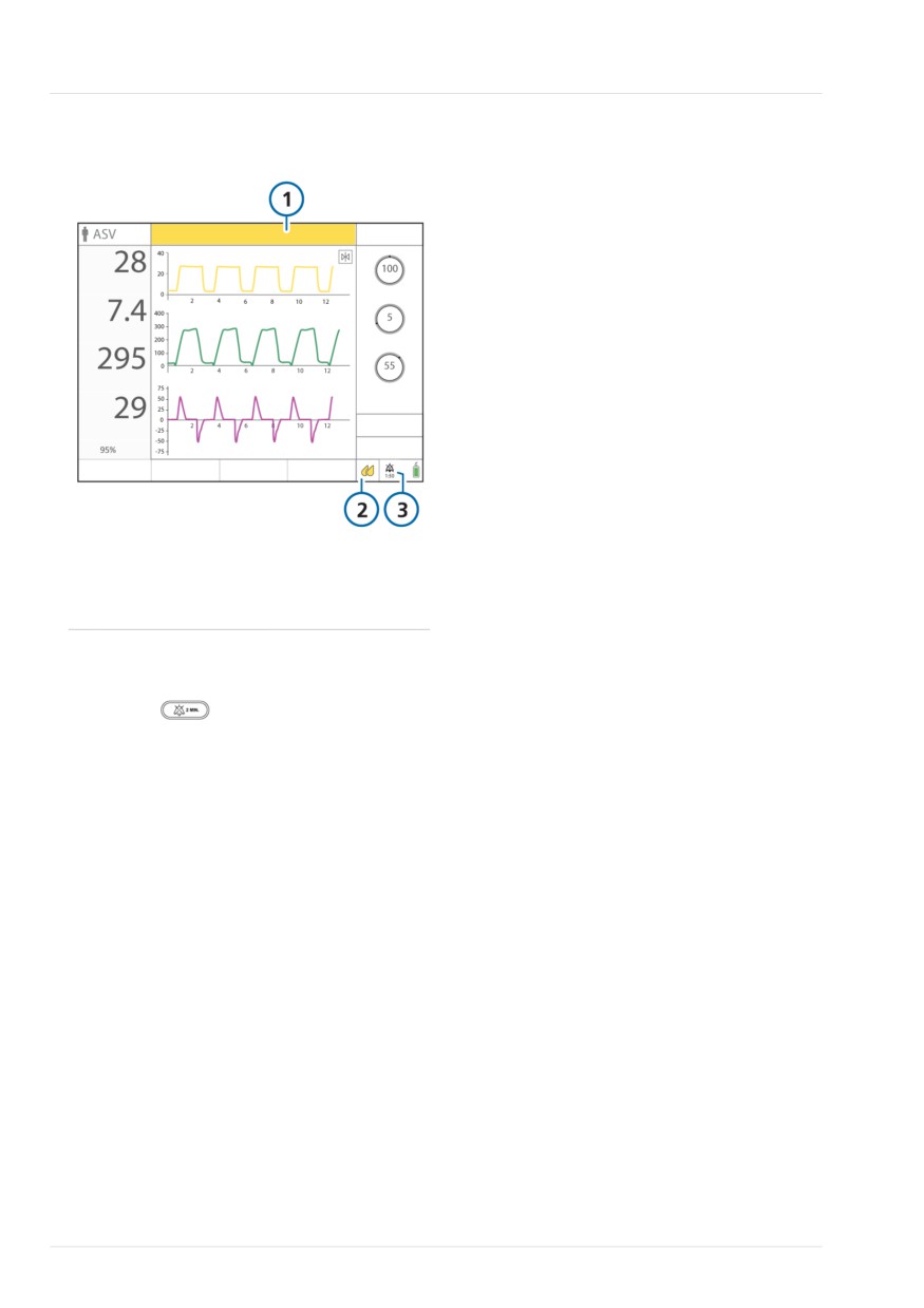
Figure 11-4. Humidifier-related alarm indicators
on ventilator (showing medium-priority alarm)
1
Alarm message
3
Audio pause
bar
indicator
2
Humidifier icon
To pause the audible humidifier alarm
4 Touch
(Audio pause) on either
the ventilator or the humidifier.
Note that touching the Audio pause
key on the ventilator also temporarily
silences the alarm on the humidifier.
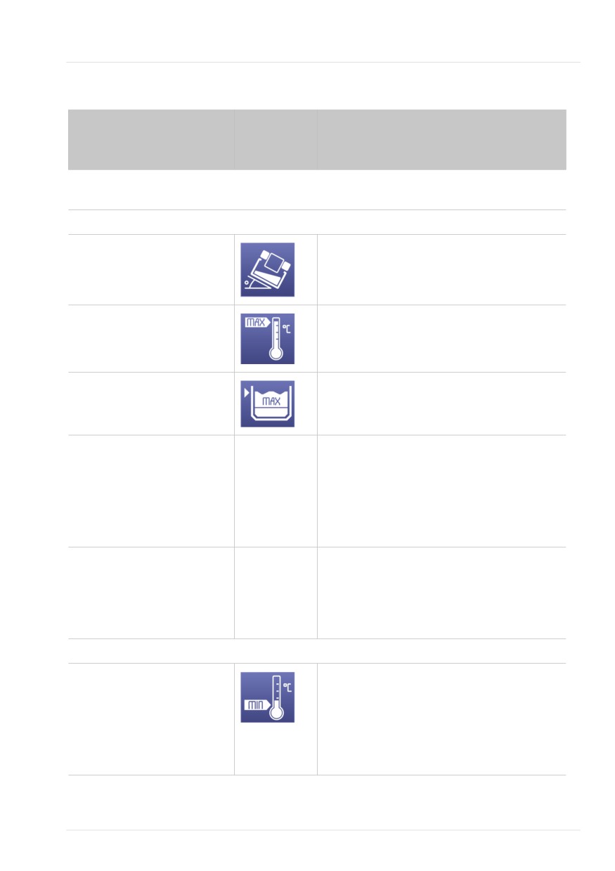
Table 11-4 lists the humidifier-related
alarms shown on the ventilator and the
associated icon on the humidifier.
238
English | 10103179/02 USA
About humidifier-related alarms
11
Table 11-4. Humidifier alarms
Alarm text on ventilator
Alarm icon
Description
on
HAMILTON-
H900
For detailed information about each alarm and actions to resolve each one, see the HAMILTON-
H900 Humidifier Instructions for Use.
High priority
Humidifier tilt
• Humidifier is at a dangerous angle of incline.
• The humidifier is at a 10° angle or higher
relative to the floor.
Humidifier chamber temp
The gas temperature at the water chamber exit
high
or at the Y-piece is above the set value.
Humidifier Y-piece temp high
Humidifier water high
The water level in the water chamber is above
the maximum level mark.
Humidifier error
n/a
•
Check humidifier operation and all connec-
tions.
•
Replace the humidifier and have it serviced.
•
If a technical fault number is displayed,
make a note of it and provide it when the
humidifier is serviced.
Check humidifier
n/a
•
When the alarm is related to something
other than the humidifier alarms listed in
High, medium, and low
priority.
this table, the ventilator displays this text.
Displayed on the ventilator
•
Check humidifier operation and all connec-
only.
tions.
Medium priority
Humidifier chamber temp low
•
Temperature too low.
Humidifier Y-piece temp low
•
The gas temperature at the water chamber
exit or at the Y-piece is below the set value.
•
Avoid direct air flow from air conditioning
and the like to the humidifier and breathing
circuit.
Hamilton Medical | HAMILTON-T1 Operator's Manual
239

11 Working with external devices
Alarm text on ventilator
Alarm icon
Description
on
HAMILTON-
H900
Humidifier water low
The water level in the chamber is low.
Humidifier check chamber
No chamber or incompatible water chamber
inserted.
Check breathing circuit limbs
The display and connection indicators show
Humidifier check left tube
which limb is faulty.
Humidifier check right tube
• No limb or defective limb connected.
• No air flow.
• A limb is not properly connected.
• The WHITE humidifier expiratory limb is con-
nected to the ventilator To patient inspira-
tory port.
Low priority
Check humidifier communica-
The Connec-
Note that the humidifier information in the
tion
tion to ventila-
ventilator System > Info > Info 2 window is
tor symbol
absent, and the Humidifier button is grayed
Displayed on the ventilator
(
) is
out.
only.
absent.
• There is a problem with the connection
between the humidifier and the ventilator.
• Ensure that the humidifier communication
cable is securely connected to the humidifier
and to the HAMILTON-H900
/COM1 port
on the ventilator communication board.
• Open the alarm buffer by touching the mes-
sage bar or the i-icon, if displayed, to reset
the alarm.
240
English | 10103179/02 USA
About humidifier-related parameters
11
11.1.7 About humidifier-related
Parameter
Description
parameters
T Y-piece
Monitored parameter.
Humidifier data is displayed in the follow-
Measured temperature at
ing locations:
the Y-piece.
• System > Settings > Humidifier window
Displayed in System >
Settings > Humidifier
• As an MMP (if configured)
window.
• System > Info > Info 2 window
In Configuration, this para-
meter can be set as an
The following parameters are related to
MMP.
humidifier operation.
Table 11-5. HAMILTON-H900-related para-
meters
Parameter
Description
HAMILTON-
Indicates the humidifier is
H900
connected, and shows the
current software version.
Displayed in the System >
Info > Info 2 window.
Set temp
Control parameter. See
Table 11-3.
T humidifier
Monitored parameter.
Measured temperature at
the water chamber exit.
Displayed in System >
Settings > Humidifier
window.
In Configuration, this para-
meter can be set as an
MMP.
Displayed as an MMP
during HiFlowO2 therapy.
T gradient
Control parameter. See
Table 11-3.
Hamilton Medical | HAMILTON-T1 Operator's Manual
241
11 Working with external devices
Table 11-7. Connectivity tasks for medical care-
11.2 Working with smart-
givers
phones and clinical networks
To ...
See ...
The HAMILTON-T1 can connect to exter-
nal devices using wired and wireless
The following tasks are performed by medical
connection types81. When used with the
personnel caring for patients.
Hamilton Connect App82, you can connect
One-time authentication
Section 11.2.1
to a ventilator equipped with the Hamilton
of your Hamilton Connect
Connect Module, and view information
App account
from the ventilator on your smartphone.
Enable a connection type Section 11.2.2
Preparing the ventilator for connectivity
comprises the following steps:
Connect using Bluetooth
Section 11.2.3
• Configuring ventilator connectivity for
Connect using Wi-Fi
Section 11.2.4
use in your institution, performed by
Access Point
technical personnel (see Table 11-6)
Connect using Wireless
Section 11.2.5
• For medical caregivers, selecting the
LAN (Wi-Fi)
connection type, then pairing a smart-
phone to the ventilator (see Table 11-7)
Set up an Ethernet
Section 11.2.6
connection
For more information about the Hamilton
Disconnect a paired
Section 11.2.7
Connect App, see the Hamilton Connect
smartphone
App Instructions for use, available on
MyHamilton.
11.2.1 Setting up a Hamilton Connect
Table 11-6. Connectivity tasks for technical per-
App account
sonnel
Before you can use the app, you must cre-
To ...
See ...
ate a user account. For details, see the
These configuration tasks are performed by
Hamilton Connect App Instructions for
technical personnel.
Use.
Configure network and
See the Hamil-
connectivity
ton Connect
11.2.2 Enabling a connection type
Communication
Depending on your institution's network
and Configura-
policy, you can enable one or more
tion Guide
connection types on the ventilator. For
Copy Connectivity confi-
Section 13.9
example, you can enable Bluetooth and
guration settings to the
Wireless LAN (Wi-Fi).
ventilator
81 Not all connection types are available in all markets.
82 Available for download on supported mobile devices. For details about the App, see the Hamilton Connect App Instructions for use.
242
English | 10103179/02 USA
Enabling a connection type
11
When enabled and configured, the follow-
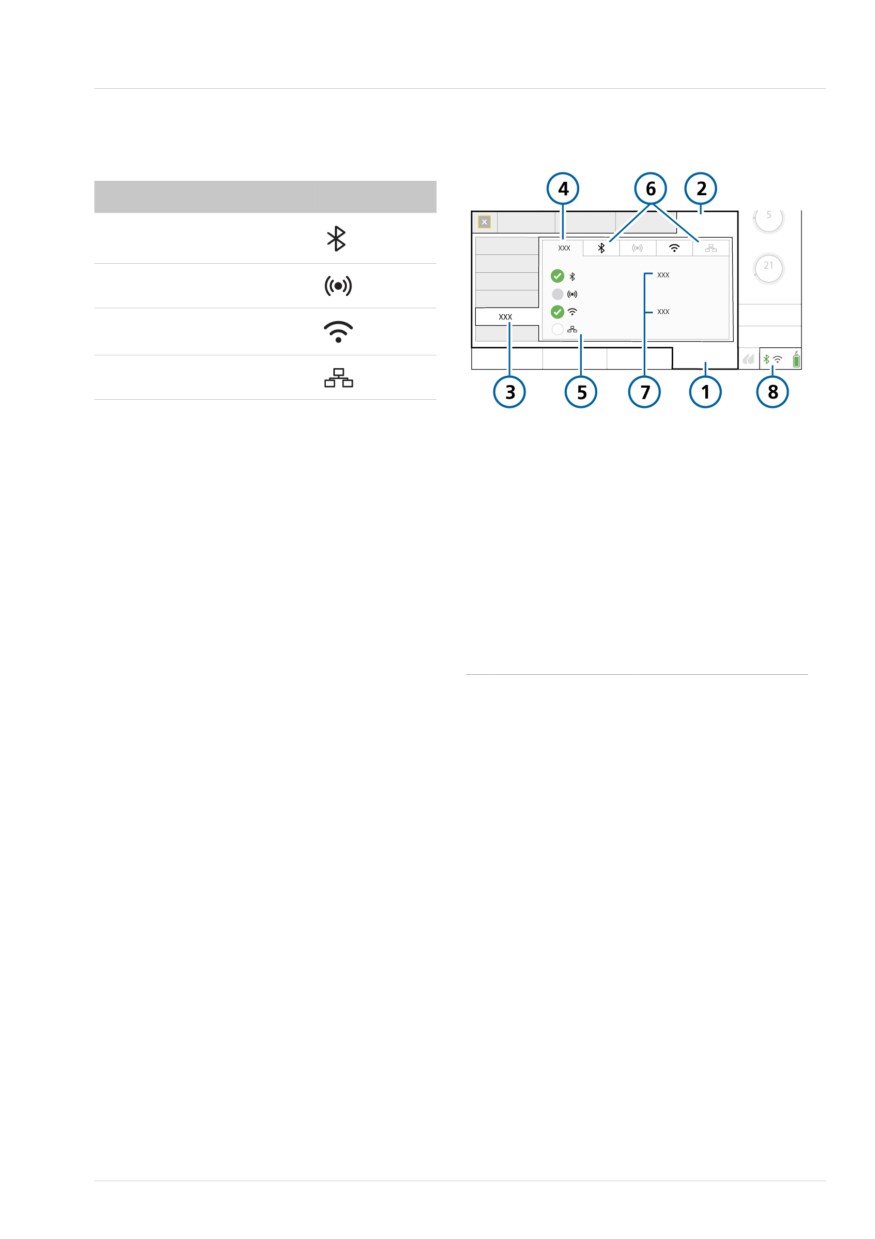
Figure 11-5. System > Settings > Connectivity >
ing connection types are supported:
Status window
Connection type
Symbol
Bluetooth
Wi-Fi Access Point
Wireless LAN (Wi-Fi)
Ethernet
1
System
5
Connection types
Note that the Wi-Fi Access Point and Wire-
less LAN (Wi-Fi) connection types cannot
2
Settings
6
Tab for each connec-
be enabled at the same time.
tion type
3
Connectivity
7
Connection status
To enable a connection type
(Bluetooth/Wi-Fi
1. Do either of the following:
Access Point) or pro-
- Touch one of the connectivity icons
file name when con-
in the lower right of the display.
nected (Wireless LAN/
Ethernet)
- Touch System > Settings > Connec-
tivity.
4
Status
8
Connectivity icons
The Connectivity window opens, dis-
playing the Status tab. See Figure
11-5.
2. Select the desired connection type(s):
- A green checkmark appears by each
selected connection type.
- The tab for the selected connection
type is enabled.
- The connection shortcut icon turns
white.
Hamilton Medical | HAMILTON-T1 Operator's Manual
243
11 Working with external devices
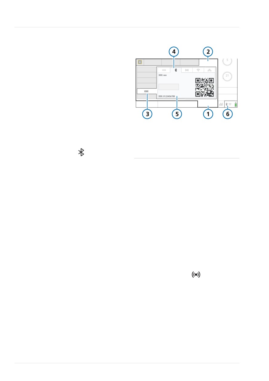
11.2.3 Setting up a Bluetooth
Figure 11-6. Bluetooth window
connection
The Bluetooth wireless technology
connection type allows you to directly
connect your smartphone to the ventila-
tor. You do not need to be on your insti-
tution's network.
To connect using Bluetooth
4
Before proceeding, ensure that Blue-
tooth is enabled on your smartphone.
1.
Enable Bluetooth on the ventilator, if
1
System
4
Bluetooth
needed. See Section 11.2.2.
2
Settings
5
Device name, PIN,
2.
In the System > Settings > Connectivity
QR code
window, touch the
tab.
3
Connectivity
6
Connectivity icons
The Bluetooth window opens, display-
ing the configured name of the Blue-
11.2.4 Setting up a Wi-Fi Access Point
tooth connection, PIN, and a QR code.
See Figure 11-6.
The Wi-Fi Access Point connection type
allows you to directly connect your smart-
You can now select the ventilator on
phone to the ventilator. You do not need
your smartphone.
to be on your institution's network.
3.
Follow the instructions in the Hamilton
Connect App to pair and connect to
To connect using a Wi-Fi Access Point
the ventilator.
4 Before proceeding, ensure that Wi-Fi
After your smartphone is connected:
is enabled on your smartphone.
- On the Bluetooth tab the name of
1. Enable Wi-Fi Access Point on the
the connected smartphone is display-
ventilator, if needed. See Section
ed and the Disconnect button is
11.2.2.
enabled.
2. In the System > Settings > Connectivity
- The Status tab displays Connected.
window, touch the
tab.
- The connection shortcut icon turns
green.
The Wi-Fi Access Point window opens,
displaying the configured name of the
For details about disconnecting a paired
Wi-Fi Access Point, SSID, Pre-shared-
smartphone, see Section 11.2.7.
key (PSK), PIN, and a QR code. See
Figure 11-7.
244
English | 10103179/02 USA
Setting up a Wireless LAN (Wi-Fi) connection
11
3. Follow the instructions in the Hamilton
2. In the System > Settings > Connectivity
Connect App to pair and connect to
window, touch the
tab.
the ventilator.
The Wireless LAN window opens, dis-
For details about disconnecting a paired
playing the available Access Point pro-
smartphone, see Section 11.2.7.
files, IP address, port number, network
name, PIN, and a QR code. See Figure
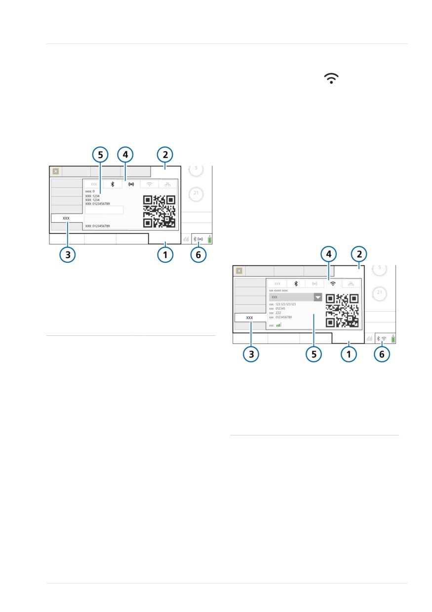
Figure 11-7. Wi-Fi Access Point window
11-8.
3. Select the desired network from the
Selected Access Point Profile dropdown
list.
4. Follow the instructions in the Hamilton
Connect App to pair and connect to
the ventilator.
Figure 11-8. Wireless LAN window
1
System
4
Wi-Fi Access Point
2
Settings
5
Device name,
Port, SSID, PSK,
PIN, QR code
3
Connectivity
6
Connectivity icons
11.2.5 Setting up a Wireless LAN
(Wi-Fi) connection
1
System
4
Wireless LAN
The Wireless LAN connection type allows
2
Settings
5
Network, IP, Port,
you to connect your smartphone to the
Name, PIN, QR
ventilator using a wireless (Wi-Fi) network.
code
To enable a Wireless LAN (Wi-Fi) connec-
3
Connectivity
6
Connectivity icons
tion
4 Before proceeding, ensure that your
smartphone is connected to a wireless
(Wi-Fi) network.
1. Enable Wireless LAN on the ventilator,
if needed. See Section 11.2.2.
Hamilton Medical | HAMILTON-T1 Operator's Manual
245
11 Working with external devices
11.2.6 Connecting to a network using
11.2.7 Disconnecting a paired smart-
Ethernet
phone
The Ethernet connection type uses the
You can remove a smartphone that has
RJ-45 Ethernet port on the ventilator and
been connected (paired) to a ventilator.
an Ethernet cable to connect the ventilator
You can also disconnect a ventilator from
to a network. See Figure 2-3.
a Wireless LAN (Wi-Fi) or Ethernet net-
work.
To connect to a network using Ethernet
To disconnect a smartphone from the
1. Enable Ethernet on the ventilator, if
ventilator
needed. See Section 11.2.2.
4 Do any of the following:
2. In the System > Settings > Connectivity
- Touch Disconnect in either the Blue-
window, touch the
tab.
tooth or Wi-Fi Access Point tabs.
The Ethernet window opens, display-
- Disable the desired connection type
ing the Selected Ethernet Profile drop-
in the System > Settings > Connectivity
down list, IP address, port number,
window.
network name, PIN, and a QR code.
- Disconnect using the Hamilton Con-
See Figure 11-9.
nect App. For details, see the Hamil-
3. Follow the instructions in the Hamilton
ton Connect App Instructions for Use.
Connect App to pair and connect to
the ventilator.
To disconnect the ventilator from a Wire-
less LAN (Wi-Fi) or Ethernet network
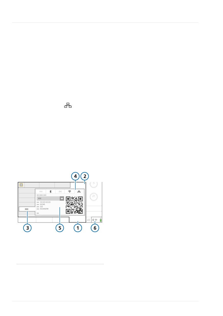
Figure 11-9. Ethernet window
4 Disable the desired connection type in
the System > Settings > Connectivity
window.
1 System
4 Ethernet
2 Settings
5 Profile, IP, Port,
Name, PIN, QR Code
3 Connectivity
6 Connectivity icons
246
English | 10103179/02 USA
12
Maintenance
12.1
Overview
248
12.2
Cleaning, disinfection, and sterilization
248
12.3
Preventive maintenance
252
12.4
Performing maintenance tasks
253
12.5
Repacking and shipping
255
247
12 Maintenance
12.1 Overview
Cleaning and disinfection information is
presented as follows:
NOTICE
• Table 12-1 lists the applicable ventila-
tor-related components, and indicates
(USA only) Only use EPA-registered and
which cleaning and disinfection meth-
approved surface cleaning/disinfection
ods can be used for each one, the fre-
agents.
quency with which the component
must be cleaned/disinfected, and any
Before proceeding, review the safety
other relevant information.
information in Chapter 1.
• Table 12-2 provides cleaning and disin-
This chapter provides information about
fection information for ventilator-
ventilator maintenance procedures and
compatible external devices and
schedule, as well as cleaning and disin-
sensors.
fection instructions.
• Table 12-3 lists the supported cleaning
All of the procedures in this chapter are to
and disinfection agents, as well as the
be performed by the operator.
concentration to be used for the venti-
lator.
For additional maintenance requirements,
contact your Hamilton Medical service rep-
• Table 12-4 lists the supported cleaning
resentative. Any documents referenced in
and disinfection agents for the CO2
this chapter are available on the
sensors.
MyHamilton website: https://www.hamil-
ton-medical.com/MyHamilton
When working with the ventilator compo-
nents, cleaning methods, and cleaning
agents, keep the following in mind:
12.2 Cleaning, disinfection, and
• Do not attempt decontamination pro-
sterilization
cedures unless specified by Hamilton
Medical or the original manufacturer.
Ventilator components must be regularly
cleaned and disinfected, using the clean-
• While we provide guidelines for agents
ing methods and solutions specific to the
and concentrations to use, if you have
individual components.
specific questions about the use of a
particular cleaning or disinfection
It is important that you use the appropri-
agent, contact the manufacturer of the
ate method and materials when cleaning
agent.
and disinfecting the ventilator and its
components, not only to avoid damaging
• After cleaning and decontaminating
the equipment, but also to avoid cross-
parts, be sure to perform any required
contamination.
tests and calibrations described in
Chapter 5.
248
English | 10103179/02 USA
Cleaning, disinfection, and sterilization
12
Table 12-1. Ventilator cleaning and disinfection methods
Part
Frequency
Cleaning/disinfection
Remarks
method
For supported cleaning and disinfection agents, see Table 12-3.
Ventilator exterior
After each
Wipe with a damp cloth
Do not clean the
including:
patient use or as
using a registered and
ventilator interior to
needed.
approved cleaning/disin-
avoid damaging inter-
• Housing
fection solution.
nal components.
• Power cables
• Gas supply hoses
• Mounting systems
Touch screen
After each
Wipe with a damp cloth
• Lock the touch
patient use or as
using a registered and
screen before
needed.
approved cleaning/disin-
cleaning. See
fection solution or a
Section 10.10.
nonabrasive glass cleaner.
• Do not use any
vinegar based solu-
tions.
• Avoid using a gritty
cloth.
Trolley-related acces-
After each
Wipe with a damp cloth
sories including:
patient use or as
using a registered and
needed.
approved cleaning/disin-
• Trolley
fection solution.
• Basket
• O2 cylinder holding
system
Autoclavable expira-
After each
Clean and sterilize accord-
For details about
tory valve
patient use or as
ing to the instructions in
assembly, installation,
needed.
the Expiratory Valve Repro-
and disassembly of
cessing Guide
the expiratory valve,
(PN 624591).
see Section 3.5.2.
CO2 sensors
After each
Wipe with a damp cloth
• Ensure that the
patient use or as
using a registered and
module/sensor is
needed.
approved cleaning/disin-
disconnected and
fection solution (Table
cooled to room
12-4). Dry before use.
temperature before
cleaning.
• Do not immerse the
module/sensor in
liquid.
Hamilton Medical | HAMILTON-T1 Operator's Manual
249

12 Maintenance
Table 12-2. Cleaning and disinfection methods for external devices
Device
Frequency
Remarks
HAMILTON-H900
After each patient use
Refer to the HAMILTON-H900 Instructions for
humidifier
or as needed.
use.
Third-party
After each patient use
Refer to the humidifier Instructions for use.
humidifiers
or as needed.
SpO2 sensors
After each patient use
Refer to the Pulse Oximetry Instructions for use
or as needed.
and the sensor manufacturer's Instructions for
use.
Table 12-3. Cleaning/disinfection agents for the ventilator
Cleaning/disinfection agent
Concentration
EPA-registered cleaning/disinfection agents
Sani-Cloth Active wipes
n/a
Approved cleaning/disinfection agents
Mikrobac Tissues wipes
n/a
mikrozid sensitive wipes
n/a
mikrozid AF liquid
Ready for use
Bacillol 30 Sensitive Foam
Ready for use
Ethanol
--
Incidin Foam
Ready for use
Incidin Pro
0.25% to 4%
Incidin Rapid
0.25% to 2%
Isopropyl alcohol
--
Mikrobac forte
0.25% to 4%
perform
3%
terralin protect
2%
250
English | 10103179/02 USA

Cleaning, disinfection, and sterilization
12
Table 12-4. Cleaning/disinfection agents for CO2 sensors
Cleaning/disinfection agent
LoFlo
CAPNOSTAT 5
(sidestream)
(mainstream)
EPA-registered cleaning/disinfection agents
Steris Coverage Spray
X
X
PDI Sani Cloth Bleach
X
PDI Sani Cloth AF
X
Approved cleaning/disinfection agents
Ammonia
X
2% glutaraldehyde solution
X
Isopropyl alcohol 70%
X
X
A 10% aqueous solution of chlorine bleach
X
X
Clinell Wipes
X
Speedy Clean
X
Tuffie
X
Tuffie 5
X
WIP Anios
X
Hamilton Medical | HAMILTON-T1 Operator's Manual
251

12 Maintenance
12.3 Preventive maintenance
The System > Info window shows the num-
ber of hours the ventilator has been in
Perform preventive maintenance on your
operation.
ventilator according to the schedule
shown in Table 12-5.
Table 12-5. Preventive maintenance schedule
Interval
Part/accessory
Procedure
Between patients and
Breathing circuit (including
Replace with sterilized or new single-
according to hospital
mask, inspiratory or expiratory
patient use parts and run the preoper-
policy
filter, flow sensor, nebulizer
ational checks (Section 5.4).
jar, expiratory valve set)
Entire ventilator
Run the preoperational checks (Section
5.4).
Every month (or more
Fan filters (rear panel), air
Check for dust and lint. If needed,
often if required)
intake filters (white filters on
replace. See Section 12.4.1.
outside of HEPA filter)
Every 6 months
Batteries
Recharge batteries by plugging the
ventilator into a primary power source
for at least 4 hours.
Yearly or as necessary
Batteries83
Have the batteries serviced.84
Galvanic O2 sensor
Replace if depleted. See Section
12.4.2.
Air intake HEPA filter
Replace. See Section 12.4.1.
Ventilator
Perform service-related preventive
maintenance.84
CO2 sensor
If the CO2 option is installed, have a
CO2 accuracy check performed.84
For the HAMILTON-H900 Humidifier, see the HAMILTON-H900 Service Manual
83 The expected service life of the battery is 3 years. To ensure proper battery function, follow the recommended preventive mainte-
nance schedule.
84 Must be performed by Hamilton Medical authorized service personnel according to instructions in the Service Manual.
252
English | 10103179/02 USA
Performing maintenance tasks
12
12.4 Performing maintenance
tasks
The following sections describe how to
clean and replace filters, batteries, and a
galvanic O2 sensor.
12.4.1 Maintaining the filters
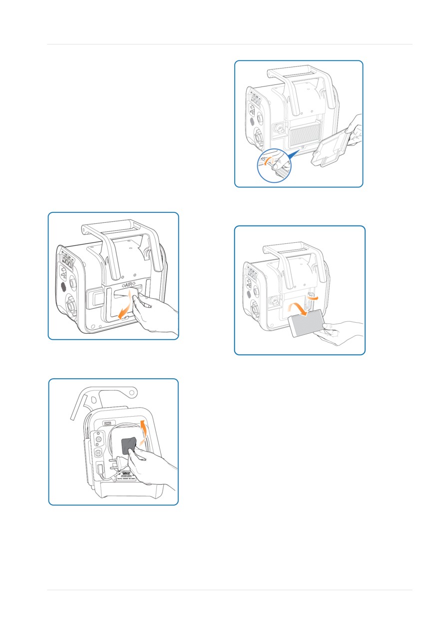
Replacing air and HEPA filters
Figure 12-1. Step 1. Remove and replace air
filter.
Figure 12-4. Step 4. Remove and replace HEPA
filter. Replace back cover when finished.
Figure 12-2. Step 2. Remove and replace fan
filter.
For details about the NBC filter adapter,
see the NBC Filter Adapter Instructions for
use.
Figure 12-3. Step 3. Remove back panel.
Hamilton Medical | HAMILTON-T1 Operator's Manual
253
12 Maintenance
12.4.2 Replacing the galvanic O2
12.4.4 Replacing batteries
sensor
Figure 12-6. Step 1. Pull the cover open.
Before proceeding, review the safety
information in Chapter 1.
Remove the back cover first (Section
12.4.1, step 3).
To replace the sensor, reverse the steps.
Figure 12-5. Remove connection cable (1).
Figure 12-7. Step 2. Turn metal clip to the left
Unscrew the sensor counter-clockwise (2) and
and up.
remove (3).
Figure 12-8. Step 3. Pull white tab to remove
battery.
12.4.3 Charging and storing batteries
To maintain the battery charge and to
prolong the life of the battery, keep the
ventilator connected to its primary power
source.
Figure 12-9. Step 4. Insert new battery, then
turn clip to the right and down.
Have the battery recharged every
6 months, depending on storage condi-
tions. For details, see Section 15.4.
254
English | 10103179/02 USA
Repacking and shipping
12
12.5 Repacking and shipping
CAUTION
Inform Hamilton Medical if you are ship-
ping a contaminated (nonsterilized and
nondisinfected) device for service.
If you must ship the ventilator, use the
original packing materials. If these materi-
als are not available, contact your Hamil-
ton Medical representative for replace-
ment materials.
Hamilton Medical | HAMILTON-T1 Operator's Manual
255
13
Configuration
13.1
Overview
258
13.2
Accessing Configuration mode
258
13.3
Configuring general settings
258
13.4
Selecting mode options
259
13.5
Configuring MMPs
260
13.6
Defining Quick setups
261
13.7
Activating SpO2 and CO2 measurement
262
13.8
Configuring CPR ventilation
262
13.9
Configuring connectivity settings
262
13.10
Copying configuration settings
265
13.11
Configuring device options
266
257
13 Configuration
13.1 Overview
13.3.1 Selecting the default language
During configuration, you set up the venti-
To select the user interface language
lator with a default language, main
4 Touch General > Language and select
monitoring parameter display, startup
the desired language.
settings for a new patient, and units of
measure, among other settings.
13.3.2 Selecting the units of measure
13.2 Accessing Configuration
To select the units of measure
mode
4 Touch General > Units and select the
unit of measure for pressure, length,
You can access all Configuration mode
and CO2.
settings when the ventilator is in Standby.
Access requires a configuration code; con-
13.3.3 Enabling the communication
tact your administrator.
interface
To access Configuration mode
You can connect external devices to the
1. Touch Tools > Configuration.
ventilator using the communication inter-
2. Using the keys on the onscreen key-
face. For a list of the communication pro-
pad, type the configuration code; then
tocols, see Table 2-2. For details about
touch Enter.
configuring communication with devices
The Configuration button is enabled.
using the Hamilton Connect App, see
Section 13.9.
3. Touch Configuration.
To select the communication protocol
The Configuration window appears, dis-
playing the Language window.
1. Touch Connectivity > More.
2. Select the desired protocol for use
You can now define settings and add
from the RS232 Protocol dropdown
options.
list.
3. Restart the ventilator.
13.3 Configuring general
The ventilator must be restarted to
settings
establish communication using the
selected protocol.
You can configure some general default
settings for the ventilator, including lan-
For setup and configuration details, see
guage, units of measure, communication
the Communication Interface User Guide,
interface to use, and minimum loudness
available on MyHamilton.
for alarms.
258
English | 10103179/02 USA
Setting the minimum alarm loudness (volume)
13
13.3.4 Setting the minimum alarm
To set the flow sensor sensitivity
loudness (volume)
1. In Configuration, touch General >
More.
You can specify a minimum alarm loud-
ness (volume) setting for the ventilator.
2. Activate the FS alarm sensitivity control
Once set, the ventilator operator cannot
and set it to the desired value.
set the alarm volume below the value set
Increasing the value lowers sensitivity;
here in Configuration.
decreasing the value increases sensitiv-
ity.
To set the minimum alarm loudness
1. Touch General > More.
13.3.6 Setting the maximum available
2. Touch the Min. loudness button and
Flow in HiFlowO2 for neonates
choose the minimum alarm volume to
allow on the device.
You can specify the maximum Flow that
can be set in HiFlowO2 for neonatal
The setting is applied to the ventilator.
patients. Once set, the ventilator operator
Note that if the new minimum is greater
cannot set Flow above the value set here
than the currently set alarm volume, the
in Configuration.
alarm volume is reset to the new mini-
mum level.
To specify the maximum Flow setting in
HiFlowO2 for neonates
To verify the setting, check the Loudness
1. Touch General > More.
value in the System > Settings window.
2. Touch the HiFlowO2 limitation control
and choose the maximum setting to
13.3.5 Setting sensitivity for Check
allow on the device.
flow sensor for water alarm
Applicable for Neonatal patients only.
13.4 Selecting mode options
Under certain conditions, water may accu-
You can set the following:
mulate in the flow sensor, which can
• Mandatory breath timing philosophy to
result in overstated volume measure-
use for PCV+ and APVcmv modes
ments.
• Naming convention for volume-control-
You can set how sensitive the alarm trig-
led, pressure-adaptive modes
ger for water in the flow sensor is. Sensi-
tivity refers to the deviation from the dry
• ASV version
value that the flow sensor tolerates before
• Enable the TI max control for certain
the ventilator generates the Check flow
invasive modes
sensor for water alarm. By default, sensitiv-
ity is set to 12%. You can also turn off the
alarm.
Hamilton Medical | HAMILTON-T1 Operator's Manual
259