HAMILTON-T1. Operator's Manual (2022) - page 5
8 Monitoring ventilation
8.5 About the monitored para-
meters
The following table provides a list of the
ventilator’s monitored parameters.
You can review all parameter values in the
Monitoring window (Section 8.2.2). The
display of monitored parameters is
updated every breath or is time driven.
See Section 15.7 for parameter specifi-
cations.
For details about SpO2-related parameters,
see the Pulse Oximetry Instructions for
use.
For a comparison of Hamilton Medical
ventilation-related terminology with ISO
19223:2019, see Section 15.5.
174
English | 10103179/02 USA
About the monitored parameters
8
Table 8-3. Monitored parameters
Parameter (unit)
Definition
Pressure
AutoPEEP
The difference between the set PEEP and the calculated total PEEP within
(cmH2O)
the lungs.
AutoPEEP is the abnormal pressure generated by air “trapped” in the alve-
oli due to inadequate lung emptying. Ideally, it should be zero. AutoPEEP is
calculated using the LSF method applied to the entire breath.
Actively breathing patients can create artifacts or noise, which can affect
the accuracy of these measurements.
When AutoPEEP is present, volutrauma or barotrauma might develop. In
active patients, AutoPEEP may present an extra workload to the patient.
AutoPEEP or air trapping may result from an expiratory phase that is too
short, which may be observed under the following conditions:
• Delivered tidal volume too large
• Expiratory time too short or respiratory rate too high
• Circuit impedance too high or expiratory airway obstruction
• Peak expiratory flow too low
AutoPEEP is also referred to as intrinsic PEEP.
Driving pressure,
A calculated value showing the ratio of tidal volume to static compliance,
ΔP
which reflects the difference between Pplateau and PEEP.
(cmH2O)
PEEP/CPAP
Monitored PEEP/CPAP. The airway pressure at the end of exhalation.
(cmH2O)
Measured PEEP/CPAP may differ slightly from the set PEEP/CPAP, especially
in spontaneously breathing patients.
ΔPinsp
Inspiratory pressure, the automatically calculated target pressure (additional
(cmH2O)
to PEEP) applied during the inspiratory phase.
Also displayed in the Vent Status panel.
Not all modes use the ΔPinsp parameter. Rather, this target pressure is set
using the following parameters, depending on the selected mode:
• APVcmv, APVsimv, ASV: Automatically calculated target pressure
• PCV+: ΔPcontrol setting
• PSIMV+, NIV-ST: ΔPinsp setting
• SPONT, NIV: ΔPsupport setting
• APRV, DuoPAP: P high setting
Hamilton Medical | HAMILTON-T1 Operator's Manual
175
8 Monitoring ventilation
Parameter (unit)
Definition
Pmean
Mean airway pressure. The absolute pressure, averaged over the breath
(cmH2O)
cycle.
Pmean is an important indicator of the possible impact of applied positive
pressure on hemodynamics and surrounding organs.
Ppeak
Peak airway pressure. The highest pressure during the previous breath
(cmH2O)
cycle.
It is influenced by airway resistance and compliance. Ppeak may differ
noticeably from alveolar pressure if airway resistance is high. This value is
always displayed.
Pplateau
Plateau or end-inspiratory pressure. The pressure measured at the end of
(cmH2O)
inspiration when flow is at or close to zero.
Used as a rough representation of alveolar pressure. Pplateau is displayed
for mandatory and time-cycled breaths.
Pprox
The airway pressure at the proximal patient interface.
(cmH2O)
Displayed only in HiFlowO2 when a flow sensor is connected.
Flow
Exp Flow
Peak expiratory flow.
(l/min)
Flow
The flow of gas to the patient in HiFlowO2.
64
(in HiFlowO2)
(l/min)
Flow (in nCPAP/
Only active in nCPAP and nCPAP-PC modes.
nCPAP-PC)
Displays the current flow as follows:
(l/min)
• In nCPAP mode, this value is the average flow, updated every second.
• In nCPAP-PC mode, this value is the average flow during expiration,
updated every breath.
Displayed in the Monitoring window.
Flow is affected by the setting of the Flow alarm. See Chapter 9.
Insp Flow
Peak inspiratory flow, spontaneous or mandatory. Measured every breath.
(l/min)
64 Only displayed as an MMP; not displayed in the Monitoring window.
176
English | 10103179/02 USA
About the monitored parameters
8
Parameter (unit)
Definition
Volume
ExpMinVol
Expiratory minute volume. The moving average of the monitored expiratory
MinVol NIV
volume per minute over the last 8 breaths. ExpMinVol changes to MinVol
(l/min)
NIV in noninvasive modes. MinVol NIV is an adjusted parameter taking leak-
age into account.
MVSpont
Spontaneous expiratory minute volume.
MVSpont NIV
The moving average of the monitored expiratory volume per minute for
(l/min)
spontaneous breaths, over the last 8 mandatory and spontaneous breaths.
In noninvasive ventilation modes, MVSpont is replaced by MVSpont NIV.
MVSpont NIV is an adjusted parameter taking leakage into account.
VLeak
Due to the leakage at the patient interface, displayed exhaled volumes in
(%)
the noninvasive modes can be substantially smaller than the delivered
MVLeak
volumes.
(l/min)
The flow sensor measures the delivered volume and the exhaled tidal
volume; the ventilator displays the difference as VLeak in % and as MVLeak
in l/min, averaged over the past 8 breaths.
VLeak/MVLeak can indicate leaks on the patient side of the flow sensor.
They do not include leakage between the ventilator and the flow sensor.
Use VLeak and MVLeak to assess the fit of the mask or other noninvasive
patient interface.
VTE
Expiratory tidal volume, the volume exhaled by the patient.
VTE NIV
It is determined from the flow sensor measurement, so it does not show
(ml)
any volume added due to compression or lost due to leaks in the breathing
circuit.
If there is a gas leak on the patient side, the displayed VTE may be less than
the tidal volume the patient actually receives.
In noninvasive ventilation modes, VTE is replaced by VTE NIV. VTE NIV is an
adjusted parameter taking leakage into account
VTESpont
Spontaneous expiratory tidal volume, the volume exhaled by the patient.
(ml)
If there is a gas leak on the patient side, the displayed VTESpont may be
less than the tidal volume the patient actually receives.
Only displayed for spontaneous breaths.
Hamilton Medical | HAMILTON-T1 Operator's Manual
177
8 Monitoring ventilation
Parameter (unit)
Definition
VTI
Inspiratory tidal volume, the volume delivered to the patient, determined
(ml)
from the flow sensor measurement.
If there is a gas leak on the patient side, the displayed VTI may be larger
than the displayed VTE.
Vt/IBW
Tidal volume is calculated according to ideal body weight (IBW) for adult/
Vt/Weight
pediatric patients and according to the actual body weight for neonatal
(kg)
patients.
Time
fControl
Mandatory breath frequency. The moving average of machine-delivered
(b/min)
breaths per minute over the last 8 total breaths.
fSpont
Spontaneous breath frequency.
(b/min)
The moving average of spontaneous breaths per minute over the last 8
total breaths.
fTotal
Total breathing frequency.
(b/min)
The moving average of the patient’s total breathing frequency over the last
8 breaths, including both mandatory and spontaneous breaths. When the
patient triggers a breath or the operator initiates a breath, fTotal may be
higher than the Rate setting.
I:E
Inspiratory:expiratory ratio.
Ratio of the patient’s inspiratory time to expiratory time for every breath
cycle. This includes both mandatory and spontaneous breaths. I:E may dif-
fer from the set I:E ratio if the patient breathes spontaneously.
TE
Expiratory time.
(s)
In mandatory breaths, TE is measured from the start of exhalation until the
set time has elapsed for the switch to inspiration.
In spontaneous breaths, TE is measured from the start of exhalation, as dic-
tated by the ETS setting, until the patient triggers the next inspiration. TE
may differ from the set expiratory time if the patient breathes spontane-
ously.
TI
Inspiratory time.
(s)
In mandatory breaths, TI is measured from the start of breath delivery until
the set time has elapsed for the switch to exhalation.
In spontaneous breaths, TI is measured from the patient trigger until the
flow falls to the ETS setting for the switch to exhalation. TI may differ from
the set inspiratory time if the patient breathes spontaneously.
178
English | 10103179/02 USA
About the monitored parameters
8
Parameter (unit)
Definition
Other calculated and displayed parameters
CPR Timer
Displayed as an MMP during CPR ventilation, shows how long CPR ventila-
tion has been on. For details, see Section 10.9.
Cstat
Static compliance of the respiratory system, including lung and chest wall
(ml/cmH2O)
compliances, calculated using the LSF method. Cstat can help diagnose
changes in elastic characteristics of the patient’s lungs.
Actively breathing patients can create artifact or noise, which can affect the
accuracy of these measurements.
Oxygen
Oxygen concentration of the delivered gas. It is measured by an O2 sensor
(%)
in the inspiratory pneumatics.
This parameter is not displayed if the O2 sensor is not installed, is defective,
is not a genuine Hamilton Medical part, or if oxygen monitoring is disabled.
P0.1
Airway occlusion pressure. The pressure drop during the first 100 ms when
(cmH2O)
a breath is triggered. P0.1 indicates the patient’s respiratory drive and
patient inspiration effort.
P0.1 applies only to patient-triggered breaths.
A P0.1 value of -3 cmH2O indicates a strong inspiratory effort, and a value
of -5 cmH2O indicates an excessive effort, possibly because the patient is
“air hungry” (peak inspiratory flow or total ventilatory support is inade-
quate) or has an excessive drive.
If P0.1 is below -3 cmH2O:
• Increase pressure or volume settings (depending on mode)
• Increase %MinVol (ASV mode only)
• Shorten P-ramp
Hamilton Medical | HAMILTON-T1 Operator's Manual
179
8 Monitoring ventilation
Parameter (unit)
Definition
PTP
Inspiratory pressure time product.
(cmH2O*s)
The measured pressure drop required to trigger the breath multiplied by
the time interval until the PEEP/CPAP level is reached at the beginning of
inspiration.
PTP is valid for patient-initiated breaths only, and indicates work by the
patient to trigger the breath. The work depends on:
• The intensity of the patient’s effort
• The trigger sensitivity
• The volume and resistance of the breathing circuit
PTP does not indicate total patient work but is a good indicator of how
well the ventilator is adjusted for the patient.
If PTP values increase, do the following:
• Increase trigger sensitivity
• Decrease P-ramp
RCexp
Expiratory time constant. The rate at which the lungs empty, as follows:
(s)
Actual TE, % emptying
1 x RCexp, 63%
2 x RCexp, 86.5%
3 x RCexp, 95%
4 x RCexp, 98%
RCexp is calculated as the ratio between VTE and flow at 75% of the VTE.
Normal values in intubated adult patients:
• Short, < 0.6 seconds: restrictive disease (ARDS, atelectasis, chest wall
stiffness)
• Normal, 0.6 to 0.9 seconds: normal compliance and resistance, or com-
bined decreased compliance and increased resistance
• Long, > 0.9 seconds: obstructive disease (COPD, asthma), broncho-
spasm, ET tube obstruction, or incorrect positioning
Use RCexp to set the optimum TE (Goal: TE ≥ 3 x RCexp):
• With passive patients: Adjust Rate and I:E
• With active patients: Increase ΔPsupport and/or ETS to achieve a longer
TE
These actions may reduce the incidence of AutoPEEP.
180
English | 10103179/02 USA
About the monitored parameters
8
Parameter (unit)
Definition
Rinsp
Resistance to inspiratory flow caused by the endotracheal tube and the
(cmH2O / (l/s))
patient’s airways during inspiration.
It is calculated using the LSF method applied to the inspiratory phase. Also
displayed in the Dynamic Lung panel.
Actively breathing patients can create artifact or noise, which can affect the
accuracy of these measurements.
RSB
Rapid shallow breathing index.
(1 / (l*min))
The total breathing frequency (fTotal) divided by the exhaled tidal volume
(VTE).
Because a patient with dyspnea typically takes faster and shallower breaths
than a non-dyspnoeic patient, RSB is high in the dyspnoeic patient and low
in the non-dyspnoeic patient.
RSB is often used clinically as an indicator of a ventilated patient’s readiness
for weaning.
RSB is only significant for spontaneously breathing patients weighing more
than 40 kg and is only shown if 80% of the last 25 breaths were spontane-
ous.
Ventilation time
Displayed in the Controls > Patient window, shows how long the patient
has been ventilated. For details, see Section 8.6.
Humidifier related
T Y-piece
For HAMILTON-H900 humidifier only. See Table 11-5.
(°C)
T humidifier
For HAMILTON-H900 humidifier only. See Table 11-5.
(°C)
CO2 related
FetCO2
Fractional end-tidal CO2 concentration.
(%)
Permits assessment of PaCO2 (arterial CO2). Note that it is inaccurate in
pulmonary embolism.
Available when a CO2 sensor is connected and enabled.
PetCO2
End-tidal CO2 pressure.
(mmHg)
The maximum partial pressure of CO2 exhaled during a tidal breath (just
before the start of inspiration). It represents the final portion of air that was
involved in the exchange of gases in the alveolar area, thus providing a reli-
able index of CO2 partial pressure in the arterial blood under certain cir-
cumstances.
PetCO2 does not reflect PaCO2 in the case of a pulmonary embolism.
Available when a CO2 sensor is connected and enabled.
Hamilton Medical | HAMILTON-T1 Operator's Manual
181
8 Monitoring ventilation
Parameter (unit)
Definition
slopeCO2
Slope of the alveolar plateau in the PetCO2 curve, indicating the volume/
(%CO2/l)
flow status of the lungs.
Available when a CO2 mainstream sensor is connected and enabled.
V’alv
Alveolar minute ventilation.
(ml/min)
Permits assessment of actual alveolar ventilation (as opposed to minute
ventilation).
Valv * f (normalized to 1 min)
Available when a CO2 mainstream sensor is connected and enabled.
V’CO2
CO2 elimination.
(ml/min)
Net exhaled volume of CO2 per minute. Permits assessment of metabolic
rate (for example, it is high with sepsis) and treatment progress.
Available when a CO2 mainstream sensor is connected and enabled.
VDaw
Airway dead space.
(ml)
Gives an effective, in-vivo measure of volume lost in the conducting air-
ways. A relative increase in dead space points to a rise in respiratory insuffi-
ciency and can be regarded as an indicator of the current patient situation.
Patients with high dead space values are at particular risk if the muscles
also show signs of fatigue.
Available when a CO2 mainstream sensor is connected and enabled.
VDaw/VTE
Airway dead space fraction at the airway opening.
(%)
Available when a CO2 mainstream sensor is connected and enabled.
VeCO2
Exhaled CO2 volume, updated breath by breath.
(ml)
Available when a CO2 mainstream sensor is connected and enabled.
ViCO2
Inspired CO2 volume, updated breath by breath.
(ml)
Available when a CO2 mainstream sensor is connected and enabled.
Vtalv
Alveolar tidal ventilation.
(ml)
VTE - VDaw
Available when a CO2 mainstream sensor is connected and enabled.
182
English | 10103179/02 USA
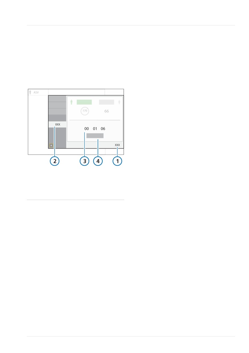
Viewing patient ventilation time
8
8.6 Viewing patient ventilation
• When you select Last patient in the
Standby window, the timer continues
time
from the last total time recorded.
The Controls > Patient window displays a
• When you touch Reset, the timer resets
timer that shows how long the patient has
to 0.
been ventilated.
When the timer is reset, an entry is made
Figure 8-21. Ventilation time
to the Event log recording the time of the
reset, as well as how long the ventilator
had been running prior to the reset.
To reset the timer to 0
1. Touch Controls.
2. In the Controls window, touch the
Patient tab.
3. Touch Reset.
The timer starts again at 00d 00h 00min.
8.7 Viewing device-specific
1
Controls
3
Ventilation time
information
(days, hours,
minutes)
The System > Info windows display device-
2
Patient
4
Reset
specific information including serial num-
ber, model, operating hours, hours since
startup, battery capacity, oxygen
The timer records time as follows:
consumption, software version, and
• The timer starts when you start ventila-
installed options.
tion.
The System > Info > About window pro-
• When you enter Standby, the timer
vides information about third-party open
pauses. It picks up again from the last
source libraries that were used to develop
value when you exit Standby and return
the ventilator software.
to active ventilation.
To view device-specific information
• When you set up a new patient in the
1. Touch System.
Standby window, and start ventilation,
the timer resets to 0.
2. If needed, touch the Info tab.
Hamilton Medical | HAMILTON-T1 Operator's Manual
183
8 Monitoring ventilation
184
English | 10103179/02 USA
9
Responding to alarms
9.1
Overview
186
9.2
About the alarm buffer
190
9.3
Adjusting alarm loudness (volume)
192
9.4
Troubleshooting alarms
193
185
9 Responding to alarms
9.1 Overview
In the event of certain technical failures,
the ventilator switches to Safety ventilation
Operator-adjustable and nonadjustable
(Section 7.6). This gives you time to
alarms together with a visual alarm indica-
arrange for corrective actions, including
tor notify you of conditions that require
organizing a replacement ventilator.
your attention.
When an alarm condition is serious
These alarms are categorized as high,
enough to possibly compromise safe venti-
medium, or low priority, as described in
lation, the device defaults to the Ambient
Table 9-1. The ventilator's visual alarm
state (Section 7.6). The ventilator immedi-
indications are described in Figure 9-1.
ately stops gas flow to the patient. The
release valve and expiratory valve are
Additional alarms conditions are associ-
opened, letting the patient breathe room
ated with technical fault and technical
air unassisted.
note alarms, as well as informational mes-
sages.
When reviewing alarms, you can access
on-screen alarm troubleshooting help in
You can view active alarms in the alarm
the Alarms > Buffer window. See Section
buffer (Figure 9-2). Information about the
9.2.1.
alarm is also stored in the Event log.
For details on setting alarm limits, see
Alarms are indicated in the color associ-
Section 5.7.
ated with the alarm priority as follows:
•
The alarm lamp on top of the ventilator
Table 9-1 describes the audio and visual
characteristics of these types of alarms
lights and flashes.
and provides guidance on how to
•
The message bar on the ventilator
respond.
display is shown in color and displays
the alarm text.
•
An MMP associated with an active
alarm is shown in color, together with a
colored bar to the right of the affected
parameter.
•
In the Monitoring window, a parameter
associated with an active alarm is
shown in the associated color.
•
Any affected parameter shown in the
Dynamic Lung is shown in color.
•
The Humidifier quick access icon is
shown in the associated color when a
related alarm is active.
•
The alarm text is displayed in the alarm
buffer.
186
English | 10103179/02 USA
Overview
9
Table 9-1. Alarm indicators
Alarm
Message bar
Alarm lamp /
Audio
Action required
type
Alarm status
indicator
High
Red, with
Red, flashing
A sequence of
The patient’s safety is
priority
alarm mes-
5 beeps, repeated
compromised. The
sage
until the alarm is
problem needs immedi-
reset. If the audi-
ate attention.
ble alarm is not
silenced during
the first minute,
the continuous-
tone buzzer also
sounds.
Medium
Yellow, with
Yellow, flashing
A sequence of
The patient needs
priority
alarm mes-
3 beeps, repeated
prompt attention.
sage
periodically.
Low
Yellow, with
Yellow, solid
Two sequences of
Operator awareness is
priority
alarm mes-
beeps. This is not
required.
sage
repeated.
Technical
Red, with the
Red, flashing
Same as for high-
The ventilator enters
fault
text, Safety
priority alarm, if
Safety ventilation, or, if
ventilation,
technically possi-
it cannot safely venti-
Safety mode,
ble. At a mini-
late, the Ambient state.
or Technical
mum, a continu-
• Provide alternative
fault: xxxxxx
ous buzzer tone.
ventilation.
The buzzer
• Turn off the ventila-
cannot be
tor.
silenced.
• Have the ventilator
serviced.
Hamilton Medical | HAMILTON-T1 Operator's Manual
187
9 Responding to alarms
Alarm
Message bar Alarm lamp /
Audio
Action required
type
Alarm status
indicator
Technical Depends on
Same as the asso- Same as the asso- A technical alarm
event
severity of the
ciated alarm level ciated alarm level. cannot typically be cor-
event. Can be
rected by the operator.
low, medium,
Ventilation continues.
or high.
If needed, have the
ventilator serviced.
Technical Provides tech-
--
--
No action is required.
note
nical informa-
tion about a
hardware or
software
issue, display-
ed only in the
Event log.
188
English | 10103179/02 USA
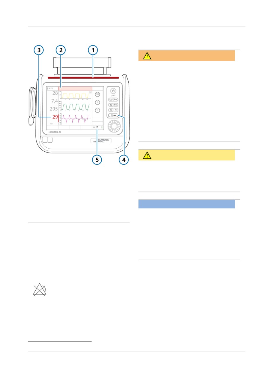
Alarm limit indicators
9
Figure 9-1. Visual alarm indications
9.1.2 Responding to an alarm
WARNING
When an Audio pause is active, the
following critical alarms still generate an
audible alarm:
• Apnea
• External power loss
• Oxygen supply failed
• Technical events: 231003, 243001,
243002, 283007, 284003, and
285003
• All technical faults
CAUTION
Carefully set alarm limits according to
1
Alarm lamp
4
Audio pause key
the patient's condition. Setting limits too
2
Message bar
5
Audio pause indi-
high or too low defeats the purpose of
cator and count-
the alarm system.
down
3
MMP and colored
NOTICE
bar associated
The factory default alarm limit settings
with alarm
are set in line with the selected patient
group, allowing for unattended monitor-
9.1.1 Alarm limit indicators
ing. These settings, however, can never
replace individual review of the patient
Alarm limits are shown in the Alarms >
and adjustment of alarm limits based on
Limits windows.
their condition.
When an alarm limit is disabled, that is, no
limit applies, the device shows the follow-
Alarms may result from either a clinical
ing Alarm Off symbol65:
condition or an equipment issue. In addi-
tion, a single alarm condition can generate
multiple alarms.
Your search for the causes of the alarm
For details about setting alarm limits, see
condition should be assisted by, but not
Section 5.7.
limited to, the alarm messages displayed.
65 Not available in all markets.
Hamilton Medical | HAMILTON-T1 Operator's Manual
189
9 Responding to alarms
To respond to an alarm
The display also indicates an Audio pause is
engaged as follows (Figure 9-1):
1. Approach the patient immediately.
2. Secure sufficient and effective ventila-
• The Audio pause indicator is displayed.
tion for the patient.
• A countdown timer on the main display
You can pause the audible alarm, if
shows the remaining time for the Audio
appropriate and available. See Section
pause.
9.1.3.
When the time expires and the issue has
3. Correct the alarm condition from the
not yet been resolved, an audible alarm
alarm messages. See Section 9.4.
sounds again.
For an informational message, wait
three (3) seconds for the message to
disappear, or follow the message
9.2 About the alarm buffer
instructions as appropriate.
The alarm buffer shows up to 5 active
For a technical fault, remove the venti-
alarm messages or up to 6 inactive alarm
lator from use, note the fault code,
messages:
and have the ventilator serviced.
•
The alarm buffer shows active alarms as
4. If appropriate, readjust the alarm limit.
they are generated (Figure 9-2). The
alarm messages also alternate in the
9.1.3 Temporarily silencing an alarm
message bar. Active alarms are shown
in wide color-coded boxes.
One component of an alarm is the audible
alarm sound. With most alarms, you can
•
If no alarms are active, the alarm buffer
pause (silence) the alarm sound for two
shows the most recent inactive alarms
minutes at a time.
(Figure 9-3). Inactive alarms are shown
in narrow color-coded boxes. In addi-
To temporarily silence an alarm
tion, the i-icon is visible on the display.
4 Press
(Audio pause) on the front
•
Touch an alarm entry to view trouble-
of the ventilator (Figure 10-2).
shooting help directly on the display.
The audible ventilator alarm is muted
for two minutes. Pressing the key a
second time cancels the Audio pause.
The indicator light next to the Audio pause
key is continuously lit red while an Audio
pause is active.
190
English | 10103179/02 USA
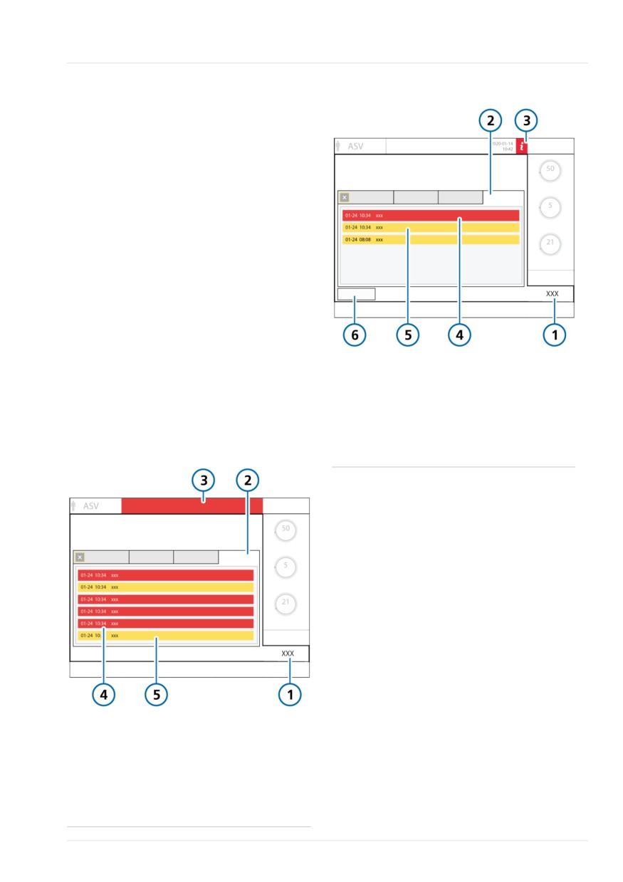
About the alarm buffer
9
To view alarms
Figure 9-3. Alarm buffer with inactive alarms
4 Open the Alarms > Buffer window by
doing one of the following:
- Touch an active alarm in the mes-
sage bar at the top of the display
(Figure 9-2).
- Touch the inactive alarm indicator
(the i-icon) (Figure 9-3).
- Touch the Audio pause indicator at
the bottom right of the display (Figure
9-1).
- Touch Alarms > Buffer.
The most recent alarm is at the top of the
list.
To clear the list of inactive alarms
1
Alarms
4
Inactive high-priority
alarm (red)
4 Touch the Reset button (Figure 9-3).
2
Buffer
5
Inactive low- or
Closing the alarm buffer does not
medium-priority
erase its contents.
alarm (yellow)
Figure 9-2. Alarm buffer with active alarms
3
i-icon
6
Reset
1
Alarms
4
High-priority alarm
(red)
2
Buffer
5
Low- or medium-
priority alarm
(yellow)
3
Alarm text in message bar
Hamilton Medical | HAMILTON-T1 Operator's Manual
191
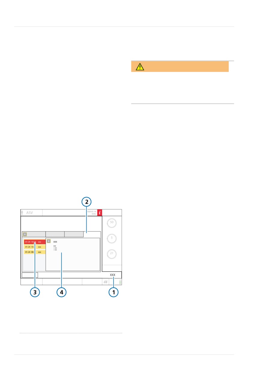
9 Responding to alarms
9.2.1 Accessing on-screen
9.3 Adjusting alarm loudness
troubleshooting help
(volume)
Troubleshooting help is available for
alarms.
WARNING
To view the help for an alarm
Be sure to set the auditory alarm loud-
1. Touch the alarm message in the
ness above the ambient sound level. Fail-
buffer.
ure to do so can prevent you from hear-
ing and recognizing alarm conditions.
A Help window opens in the buffer,
providing troubleshooting information
You can set the loudness of the audible
for the selected alarm.
alarm. By default, the loudness is set to 5.
2. To view help for another alarm, touch
If you set the loudness below the default
the next alarm message.
value during a patient session, the value is
The contents of the Help window
reset to the default upon:
refresh with the new information.
• Setting up a new patient
The alarm is displayed as long as the
window is open even if the alarm is no
• Turning the ventilator off and on again
longer active.
You cannot set the loudness below the
3. Touch X to close the Help window.
minimum level configured for the device
(Chapter 13).
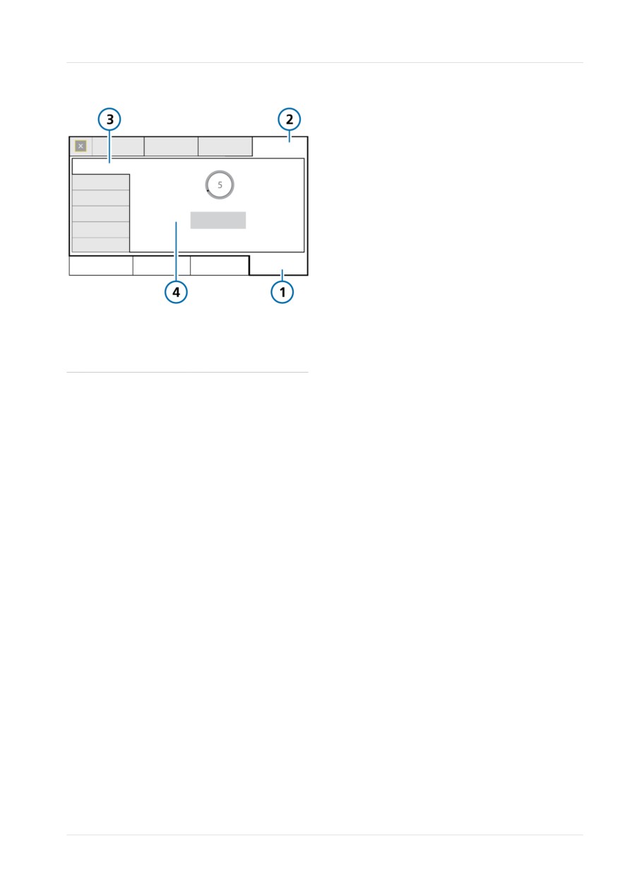
Figure 9-4. On-screen help window
To adjust the alarm loudness
1. Touch System > Settings.
2. Touch the Loudness button if the
Loudness window is not already
displayed.
3. Activate and adjust the Loudness
control, as needed.
4. Touch Test to check the loudness
level.
Ensure the loudness level is above the
ambient sound level.
5. Repeat the process as required, and
close the window.
1
Alarms
3
Selected alarm
2
Buffer
4
Alarm text and
troubleshooting
information
192
English | 10103179/02 USA
Troubleshooting alarms
9
Figure 9-5. Alarm loudness control
1
System
3
Loudness
2
Settings
4
Loudness control
and Test button
9.4 Troubleshooting alarms
Table 9-2 is an alphabetical list of the
alarm messages displayed by the
HAMILTON-T1, along with their definitions
and suggested corrective actions.
These corrective actions are sequenced to
correct the most probable issue or to
present the most efficient corrective action
first. The proposed actions, however, may
not always correct the particular problem.
If your issue is not resolved after perform-
ing the recommended tasks, contact your
Hamilton Medical authorized service per-
sonnel.
For additional information, see the appro-
priate documentation as follows:
• For SpO2-related alarms, see the Pulse
Oximetry Instructions for Use.
• For HAMILTON-H900-related alarms,
see Section 11.1.6 and the HAMILTON-
H900 Instructions for Use.
Hamilton Medical | HAMILTON-T1 Operator's Manual
193
9 Responding to alarms
Table 9-2. Alarms and other messages
Alarm
Definition
Action needed
Ambient state
The inspiratory and expiratory
Provide alternative ventilation immedi-
channels are opened, letting the
ately.
patient breathe room air unas-
sisted. See Section 7.6.
Apnea ventilation
Low priority. Backup mode was
No action required.
ended
reset, and ventilator is again venti-
lating in its original support (pre-
apnea) mode.
Apnea ventilation
Low priority. Apnea backup ventila-
•
Check patient condition.
tion has started. No breath deliv-
•
Check trigger sensitivity.
ered for the operator-set apnea
•
Check the control settings for the
time. Apnea backup ventilation is
backup mode.
on.
•
Consider changing the mode.
Apnea
High priority. No patient trigger
•
Check patient condition.
within the operator-set apnea
•
Check trigger sensitivity.
time in APVsimv, SPONT, DuoPAP,
•
Consider changing the mode.
APRV, or NIV mode. Apnea backup
is off.
ASV: Cannot
Low priority. The operator-set
•
Check patient condition.
meet target
%MinVol cannot be delivered, pos-
•
Check the Plimit setting and adjust
sibly due to setting conflicts or
if appropriate.
lung-protective rules.
•
Consider a mode change. However,
be aware that other modes may not
enforce lung-protective rules.
Battery 1, 2: Cali-
Low priority. The battery requires
Replace the battery with a properly
bration required
calibration. You may continue to
calibrated battery to continue ventila-
use the battery.
tion.
Battery 1, 2:
High priority. Battery defective.
• Replace battery.
Defective
Ventilation continues if an alterna-
• Prepare alternative ventilation.
tive power source is connected.
• If the problem still persists, have the
ventilator serviced.
194
English | 10103179/02 USA
Troubleshooting alarms
9
Alarm
Definition
Action needed
Battery 1, 2:
Low priority. Battery capacity is
•
Connect the ventilator to primary
Replacement
insufficient for reliable operation
power (AC or DC).
required
and must be replaced immedi-
•
Replace the battery.
ately.
•
If a replacement is not available,
provide alternative ventilation until
the issue is resolved.
•
If the problem still persists, have the
ventilator serviced.
Battery 1, 2: Tem-
High priority. The battery tempera-
•
Remove the ventilator from the sun
perature high
ture is higher than expected.
or other heat source.
•
Replace the battery.
•
Provide alternative ventilation until
the issue is resolved.
•
If the problem still persists, have the
ventilator serviced.
Battery 1, 2:
Low priority. The battery in use is
•
Replace the battery.
Wrong battery
not the correct battery for this
•
Connect the ventilator to primary
ventilator.
power (AC or DC).
•
Provide alternative ventilation until
the issue is resolved.
Battery communi-
High priority. Battery data is not
•
Check the battery connectors and
cation error
available. Ventilation continues.
that the battery is installed correctly.
•
Make sure the battery lock is prop-
erly closed.
•
If the problem persists, replace the
battery.
•
If the problem still persists, have the
ventilator serviced.
Hamilton Medical | HAMILTON-T1 Operator's Manual
195
9 Responding to alarms
Alarm
Definition
Action needed
Battery low
The Battery low alarm has different
•
Connect the ventilator to a primary
levels of priority depending on
power source.
battery age and condition. The
•
Install charged battery.
alarm priority levels are defined as
•
If necessary, be prepared to provide
follows:
alternative ventilation.
High priority. The ventilator is run-
ning on battery power, and the
battery charge is critically low. You
have a minimum of 5 minutes
operating time left.
If the high-priority Battery low
alarm occurs when starting up the
ventilator, you may have less than
5 minutes of operating time
remaining.
Medium priority. The ventilator is
running on battery power and the
battery charge is low.
Low priority. The ventilator is run-
ning on primary power and the
battery charge is low.
Battery power
High priority. No battery is
•
Connect the ventilator to primary
loss
present.
power (AC or DC).
•
Insert a battery.
Battery totally dis-
High priority. The battery charge
•
Connect the ventilator to primary
charged
level is below 5%. The ventilator
power (AC or DC). Connecting to
switches to the Ambient state.
primary power also charges the bat-
tery.
•
Immediately provide alternative
ventilation until the issue is resolved.
•
If the problem still persists, have the
ventilator serviced.
Blower fault
High priority. A blower malfunc-
•
Immediately provide alternative
tion was detected. A technical
ventilation.
alarm cannot typically be cor-
•
Have the ventilator serviced.
rected by the operator. The venti-
lator switches to the Ambient
state.
Blower service
Low priority. The blower has
Have the ventilator serviced.
required
reached the end of its lifespan.
196
English | 10103179/02 USA
Troubleshooting alarms
9
Alarm
Definition
Action needed
Buzzer defective
High priority. A buzzer malfunc-
•
Restart device.
tion was detected. A technical
•
Provide alternative ventilation until
alarm cannot typically be cor-
the issue is resolved.
rected by the operator.
•
If the problem persists, have the
ventilator serviced.
Check CO2 air-
Low priority. Adapter disconnec-
•
Check patient condition.
way adapter
tion, optical block, or adapter type
•
Check the airway adapter for excess
changed.
moisture accumulation /contamina-
tion by secretions.
•
Replace / perform zero calibration
on airway adapter.
Check CO2
Low priority. The CO2 sidestream
•
Check patient condition.
sampling line
sensor sampling line is occluded
•
Replace sampling line.
by water.
Check flow
Neonatal only. Water is detected
•
Remove all water from the flow
sensor for water66
inside the flow sensor, which is
sensor and flow sensor tubing.
affecting measurements.
•
You must position the flow sensor
Medium priority. You must
at a ≥ 45° angle to avoid water
acknowledge the alarm within 90
accumulation.
seconds by pressing the Audio
•
Adjust the FS alarm sensitivity
pause key. This gives you time to
control.
remove any accumulated water
from the flow sensor and tubing.
If the alarm is not acknowledged
within 90 seconds, the alarm
becomes high priority.
The alarm is active until flow
sensor measurements are again
within the expected range.
You can specify alarm sensitivity or
disable the alarm in Configuration.
See Section 13.3.5.
66 Not available in all markets.
Hamilton Medical | HAMILTON-T1 Operator's Manual
197
9 Responding to alarms
Alarm
Definition
Action needed
Check flow
High priority. Flow sensor mea-
•
Make sure the flow sensor is the
sensor
surements are out of the expected
correct type for the patient (Adult/
range.
Ped or Neonatal).
If the alarm continues for 3 conse-
•
Check the flow sensor connection
cutive breath cycles, the External
to the ventilator.
flow sensor failed alarm is genera-
•
Connect and calibrate a new flow
ted and the ventilator switches to
sensor.
Sensor Failure mode (Section
7.6.1).
Check flow
High priority. The flow sensor
•
Check the flow sensor connection
sensor tubing
tubes are disconnected or
to the ventilator.
occluded.
•
Connect and calibrate a new flow
If the alarm continues for 3 conse-
sensor.
cutive breath cycles, the External
flow sensor failed alarm is genera-
ted and the ventilator switches to
Sensor Failure mode (Section
7.6.1).
Check for
Medium priority. Internal pressure
•
Observe the patient
blockage
is above 45 cmH2O in HiFlowO2.
•
Check patient interface for
If the pressure increases further
blockage.
and exceeds 50 cmH2O, the alarm
If no blockage is observed, consider
becomes high priority, flow stops,
reducing the flow to decrease pres-
and the pressure is released.
sure.
•
Check breathing circuit limbs and
tubing for kinks.
Check patient
High priority. Generated when
Check for:
interface
using a speaking valve and the Vt
• Disconnection
low or Low pressure alarm is
• Whether cuff is fully deflated
active.
• Upper airway occlusion
For additional alarm details when
• Speaking valve is operating properly
using a speaking valve, see Table
10-1.
Check Plimit
Low priority. Inspiratory pressure,
• Check the patient for adequate
including PEEP/CPAP, is above the
ventilation.
pressure limit (Plimit).
• Adjust Plimit and/or the pressure
Does not apply in APVcmv,
control settings, as appropriate.
APVsimv, or ASV modes.
198
English | 10103179/02 USA
Troubleshooting alarms
9
Alarm
Definition
Action needed
Check settings
Low priority. A change to a
Check and confirm settings, including
control or alarm setting was not
alarms.
saved.
Circuit calibration
Medium priority, Low after silence.
Calibrate the neonatal breathing cir-
needed
The ventilator does not have cor-
cuit (Section 6.2.2).
rect calibration data.
Only active in nCPAP and nCPAP-PC
modes.
CO2 calibration
Low priority. A previous sensor
Perform the following checks, repeat-
needed
zero calibration failed.
ing the calibration after each one, until
calibration is successful:
•
Clean or replace airway adapter.
•
Perform a zero calibration of the
sensor, making sure there is no
source of CO2 near the airway
adapter.
•
Replace the airway adapter.
•
Replace the CO2 sensor.
•
If the problem persists, have the
ventilator serviced.
CO2 sensor
Low priority. The CO2 sensor sig-
•
Disconnect the sensor from the CO2
defect
nal indicates a hardware error or a
module. Wait a few seconds, and
third-party sensor is installed.
reconnect.
•
Perform a zero calibration of the
sensor. Ensure the sensor is
attached to the airway adapter
during zero calibration.
•
Replace the CO2 sensor. Make sure
the sensor is a genuine Hamilton
Medical part.
CO2 sensor
Low priority. The CO2 module is
•
Make sure a CO2 sensor is con-
disconnected
installed, but there is no signal
nected.
from the CO2 sensor. CO2
•
Check CO2 sensor connections
monitoring is enabled.
(CO2 sensor cable to module, CO2
module to ventilator).
•
If the problem persists, have the
ventilator serviced.
Hamilton Medical | HAMILTON-T1 Operator's Manual
199
9 Responding to alarms
Alarm
Definition
Action needed
CO2 sensor over
Low priority. The temperature at
• Check whether the sensor is
temperature
the CO2 sensor is too high.
affected by an external heating
source.
• Remove the sensor from the airway,
and disconnect the sensor from the
CO2 module. Reconnect.
• Verify that system is running within
the specified environmental condi-
tions. Check for excessive airway
temperature, which could be caused
by defective humidifier, heater wire,
or probe.
CO2 sensor
Low priority. The CO2 operating
Wait for the sensor to warm up.
warmup
temperature has not yet been
reached or is unstable.
CO2: Poor signal
Low priority. The CO2 sensor sig-
•
Check patient condition.
nal quality is poor.
•
Check CO2 sensor and adapter
connections.
•
Ensure that airway adapters are not
in a horizontal position relative to
the floor to reduce accumulation of
patient secretions.
If accumulation occurs, remove the
adapter, rinse with sterile water,
and reconnect.
CPR ON
Low priority. CPR ventilation is on.
•
Check and confirm settings, includ-
The alarm limits for ExpMinVol,
ing alarms.
fTotal, and Vt are set to their mini-
•
To stop CPR ventilation, press the
mum and maximum values.
Power/Standby key or change the
ventilation mode.
Device tempera-
High priority. The internal temper-
•
Remove the ventilator from the sun
ture high
ature of the ventilator is higher
or other heat source.
than expected.
•
Check the cooling fan filter and fan.
•
Prepare alternative ventilation.
•
Have the ventilator serviced.
200
English | 10103179/02 USA
Troubleshooting alarms
9
Alarm
Definition
Action needed
Disconnection on
High priority. VTE is less than one-
•
Check patient condition.
patient side
eighth of the delivered VTI, and
•
Check the breathing circuit for a
delivered VTI exceeds 50 ml.
disconnection between the patient
Applicable in invasive modes.
and the flow sensor, or for other
large leaks (for example, ET tube).
For APRV and DuoPAP modes, only
applicable during the pressure
phase.
For alarm details when using a
speaking valve, see Table 10-1.
Disconnection on
High priority. Measured VTI at the
•
Check the expiratory valve:
ventilator side
flow sensor is less than one-half of
- Check the condition of the
the delivered VTI, and delivered
expiratory valve set. If anything
VTI exceeds 50 ml.
is defective, replace.
Applicable in invasive modes.
- Check whether the expiratory
For alarm details when using a
valve is affected by any nebuliz-
speaking valve, see Table 10-1.
ing agent.
- Make sure that the expiratory
valve is properly installed.
- Check whether there is a dis-
connection at the expiratory
valve.
•
Replace the expiratory valve.
•
Check the flow sensor. If needed,
replace the flow sensor.
Exhalation
High priority. Either the end-
•
Check patient condition.
obstructed
expiratory pressure is too high or
•
Check the expiratory limb for occlu-
the end-expiratory flow is too low.
sion.
Note that you must use an inspira-
•
Check the expiratory valve set.
tory filter to prevent contamina-
Replace if needed.
tion. The ventilator may be con-
•
Check the flow sensor tubes for
taminated if no inspiratory filter is
occlusion.
used.
•
Adjust breath timing controls to
Not active when using HiFlowO2.
increase the expiratory time.
•
Provide alternative ventilation until
the issue is resolved.
•
Have the ventilator serviced.
Hamilton Medical | HAMILTON-T1 Operator's Manual
201
9 Responding to alarms
Alarm
Definition
Action needed
External connec-
Medium priority. Low after silence.
•
If no patient is connected, restart
tions disabled
The Connectivity Module is turned
the ventilator.
off. Repeated connection attempts
•
If the problem persists, have the
have failed. Ventilation can con-
ventilator serviced.
tinue, but connection with other
devices is not possible.
External flow
High priority. The external flow
•
Check flow sensor for excessive
sensor failed
sensor does not work properly.
secretions and/or water accumula-
The alarm is generated when
tion.
either the Check flow sensor or
•
Provide alternative ventilation and
Check flow sensor tubing alarm is
clean the flow sensor with sterile
active for 3 consecutive breath
water.
cycles. The ventilator switches to
•
Connect and calibrate a new flow
Sensor Failure mode (Section
sensor.
7.6.1).
Fan failure
Medium priority. There is a prob-
•
Provide alternative ventilation until
lem with the cooling fan.
the issue is resolved.
•
Disconnect the ventilator from the
patient.
•
Have the ventilator serviced.
Flip the flow
Medium priority. Either the flow
•
Check the flow sensor. The end
sensor
sensor is connected to the breath-
marked PATIENT faces the patient.
ing circuit facing the wrong direc-
•
Reverse the flow sensor tube
tion or the flow sensor connec-
connections on the ventilator.
tions to the ventilator are
•
The blue tube attaches to the blue
reversed.
connector. The clear tube attaches
Ventilation continues, but the
to the white connector.
ventilator corrects for the reversed
signal.
Flow sensor calib-
High priority during ventilation,
•
Ensure the correct flow sensor for
ration needed
low in Standby. The ventilator
the selected patient group is
does not have correct calibration
attached to the breathing circuit.
data or flow sensor cannot be cali-
•
Calibrate the flow sensor as soon as
brated.
possible.
In Standby, may indicate that the
patient group has changed.
Note that flow, volume, and pres-
sure measurements are less accu-
rate with an uncalibrated flow
sensor.
202
English | 10103179/02 USA
Troubleshooting alarms
9
Alarm
Definition
Action needed
Function key not
Medium priority. The function key
•
Turn off the ventilator using the
operational
is defective. Ventilation continues.
Power/Standby button on the back
of the device.
•
Have the ventilator serviced.
High Flow
Medium priority, Low after silence.
•
Check the patient interface and
Flow has reached the set limit.
breathing circuit for disconnection
or excessive leakage.
Only active in nCPAP and nCPAP-PC
modes.
•
Check ventilator settings and alarm
limits.
High frequency
Medium priority. The measured
•
Check the patient for adequate
fTotal exceeds the set alarm limit.
ventilation (VTE).
•
Check alarm limits.
•
Check the trigger sensitivity.
•
If the ventilator is in ASV mode, see
Section 7.8.
High minute
High priority. The measured
•
Check patient condition.
volume
ExpMinVol exceeds the set alarm
•
Check and confirm settings, includ-
limit.
ing alarms.
High oxygen
High priority.
•
Calibrate the O2 sensor.
One of the following has
•
Install a new O2 sensor.
occurred:
•
Check alarm limits (if set manually).
• If the Oxygen alarm limits are set
automatically, the measured
oxygen is more than 5% (abso-
lute) above the current Oxygen
control setting.
• If the Set Oxygen alarm limits
manually checkbox is selected,
the measured oxygen is above
the set upper limit.
Hamilton Medical | HAMILTON-T1 Operator's Manual
203
9 Responding to alarms
Alarm
Definition
Action needed
High PEEP
Medium priority. Monitored PEEP
•
Check patient condition.
exceeds (set PEEP + 5 cmH2O) for
•
Check and confirm settings, includ-
two consecutive breaths.
ing alarms.
For DuoPAP and APRV only: Alarm
•
Check the expiratory valve set for
applies to both P high and P low
possible obstructions.
settings. The alarm sounds when
•
Check for obstructions in the expira-
the monitored P high exceeds (set
tory limb.
P high + 5 cmH2O) or monitored
•
Check the flow sensor tubes for
P low exceeds (set P low +
occlusion.
5 cmH2O) for two consecutive
breaths.
If T low is set to < 3 seconds, the
High PEEP alarm is disabled for
P low settings. This reduces the
incidence of false positive alarms.
High pressure
High priority. A sigh cannot be
•
Check patient condition.
during sigh
fully delivered because excessive
•
Check the artificial airway of the
inspiratory pressure would be
patient for kinks and occlusions.
required. The sigh is partially deliv-
•
Check the breathing circuit limbs
ered.
and flow sensor tubes for kinks and
occlusions.
•
Consider disabling the Sigh function.
High pressure
High priority, Low after Audio
•
Check patient condition.
pause is activated. The measured
•
Adjust the Pressure alarm limit.
inspiratory pressure exceeds the
•
Check the artificial airway of the
set high Pressure alarm limit. The
patient for kinks and occlusions.
ventilator immediately stops gas
•
Check the breathing circuit limbs
flow to the patient and opens the
expiratory valve to reduce pressure
and flow sensor tubes for kinks and
to the PEEP/CPAP level.
occlusions.
•
Provide alternative ventilation once
If the pressure reaches 15 cmH2O
the ventilator enters the Ambient
above the high Pressure alarm
state.
limit for longer than 5 seconds,
the ventilator opens the release
valve.
If the pressure reaches 15 cmH2O
above the high Pressure alarm
limit for longer than 7 seconds,
the ventilator enters the Ambient
state.
204
English | 10103179/02 USA
Troubleshooting alarms
9
Alarm
Definition
Action needed
Inspiratory
Medium priority. The delivered Vt
• Reduce the ΔPsupport setting.
volume limitation
is more than 1.5 times the set
• Adjust the high Vt alarm limit.
high Vt alarm limit. Pressure is
reduced to PEEP level.
The APV controls reduce the pres-
sure for the next breath by 3
cmH2O.
Disabled in noninvasive modes.
For alarm details when using a
speaking valve, see Table 10-1.
Invalid communi-
Low priority. The installed com-
• Contact your Hamilton Medical
cation board
munication board is invalid.
technical representative.
• Have the ventilator serviced.
IRV
Low priority. The set I:E ratio is
Check the timing control settings.
above 1:1, leading to inverse ratio
ventilation.
Does not apply in PSIMV+PSync,
SPONT, NIV, or NIV-ST modes, or in
HiFlowO2.
JTAG not working
Low priority. A hardware compo-
Remove the ventilator from use and
nent failed the self-test during
have it serviced.
startup.
Loss of external
Low priority. The ventilator is run-
• Silence the alarm.
power
ning on battery power due to loss
• Check integrity of connection to pri-
of a primary power source.
mary power source.
• Check battery status.
• Prepare for possible power loss.
• Provide alternative ventilation until
the issue is resolved.
Hamilton Medical | HAMILTON-T1 Operator's Manual
205
9 Responding to alarms
Alarm
Definition
Action needed
Loss of PEEP
Medium priority. One of the
•
Check patient condition.
following conditions is in effect:
•
Check the breathing circuit for
• Pressure during exhalation is
leaks. Replace the breathing circuit,
below (set PEEP/CPAP - 3
if necessary.
cmH2O) for more than 10
•
Check the condition of the expira-
seconds
tory valve set. If anything is defec-
• Measured end-expiratory pres-
tive, replace.
sure is below (set PEEP/CPAP - 3
cmH2O) for two consecutive
breaths
Loudspeaker
High priority. A loudspeaker mal-
•
Check patient condition.
defective
function was detected. A technical
•
Provide alternative ventilation until
alarm cannot typically be cor-
the issue is resolved.
rected by the operator. Ventilation
•
Have the ventilator serviced.
continues.
Low frequency
Medium priority. Measured fTotal
•
Check patient condition.
is below the set alarm limit.
•
Adjust the low fTotal alarm limit.
Low minute
High priority. Measured ExpMinVol
•
Check patient condition.
volume
is below the set alarm limit.
•
Check the breathing circuit and arti-
ficial airway of the patient for leaks
and/or disconnection.
•
Check and confirm settings, includ-
ing alarms.
Low oxygen
High priority.
•
Check patient condition.
One of the following has
•
Check the oxygen supply. Provide
occurred:
an alternative source of oxygen, if
necessary.
• If the Oxygen alarm limits are set
automatically, the measured
•
Calibrate the O2 sensor.
oxygen is more than 5% (abso-
•
Provide alternative ventilation and
lute) below the current Oxygen
install a new O2 sensor.
control setting.
• If the Set Oxygen alarm limits
manually checkbox is selected,
the measured oxygen is below
the set lower limit.
206
English | 10103179/02 USA
Troubleshooting alarms
9
Alarm
Definition
Action needed
Low pressure
High priority. The set pressure
• Check patient condition.
during inspiration was not
• Check the breathing circuit for a
reached.
disconnection between the patient
and the flow sensor, or for other
large leaks.
Maximum leak
Low priority. The set Vt cannot be
• Check patient condition.
compensation
reached due to a leak.
• Inspect the system for leaks.
In APVsimv and APVcmv modes
• Suction the patient, if needed.
only.
• Ensure the high Pressure limit is
appropriate.
• Switch to a different ventilation
mode.
O2 sensor calibra-
Low priority. O2 sensor calibration
• Calibrate the O2 sensor.
tion needed
data is not within the expected
• Verify temperature settings are
range, or the sensor is new and
within environmental specifications.
requires calibration.
• Replace O2 sensor if required.
• Have the ventilator serviced.
O2 sensor defec-
Low priority. The O2 sensor is
Install a new O2 sensor.
tive
depleted.
O2 sensor missing
Low priority. There is no signal
Install an O2 sensor or use an external
from the O2 sensor.
monitor, according to ISO
80601-2-55.
O2 sensor not
Low priority. The incorrect type of
Ensure a Hamilton Medical O2 sensor
system compa-
O2 sensor is installed.
is used and it is properly installed.
tible
Obstruction
High priority. End-expiratory pres-
• Check the patient.
sure > set PEEP/CPAP + 5, or Flow
• Check the expiratory limb for occlu-
< 1 l/min.
sion.
Only active in nCPAP and nCPAP-PC
• Check the expiratory valve set.
modes.
• Check the pressure line for occlu-
sion.
• Adjust breath timing controls to
increase the expiratory time.
• Have the ventilator serviced.
Options not
High priority. Options were not
• Restart device.
found
found during startup.
• If the problem persists, have the
ventilator serviced.
Hamilton Medical | HAMILTON-T1 Operator's Manual
207
9 Responding to alarms
Alarm
Definition
Action needed
Oxygen supply
High priority. Oxygen source flow
•
Check patient condition.
failed
is lower than expected.
•
Check the oxygen supply. Provide
an alternative source of oxygen, if
necessary.
•
Check the oxygen source/supply for
potential leakage.
•
Provide alternative ventilation until
the issue is resolved.
Performance lim-
Medium priority, Low after silence.
•
Check patient condition.
ited by high alti-
The airway pressure cannot be
•
If at all possible, consider lowering
tude
reached at the current altitude.
altitude to reach the target perfor-
As long as the device remains
mance.
above the altitude limit, the pres-
•
Provide alternative ventilation until
sure cannot be reached, and the
the issue is resolved.
alarm is active.
PetCO2 high
Medium priority. PetCO2 exceeds
•
Check patient condition.
the set alarm limit.
•
Check and confirm settings, includ-
ing alarms.
PetCO2 low
Medium priority. PetCO2 is below
•
Check patient condition.
the set alarm limit.
•
Check the breathing circuit and
flow sensor/artificial airway of the
patient for leaks.
•
Check and confirm settings, includ-
ing alarms.
Pressure limit has
Low priority. The pressure limit
Make sure the pressure limit is high
changed
setting (Plimit) has changed.
enough so that sufficient pressure can
be applied for adequate breath deli-
Either the Plimit setting or the
very.
high Pressure alarm limit setting
has been adjusted by the opera-
If sufficient pressure cannot be
tor.
applied, the Pressure limitation alarm is
generated.
Changing Plimit or the high Pres-
sure alarm limit automatically
changes the other: The high Pres-
sure alarm limit is always
10 cmH2O greater than Plimit.
208
English | 10103179/02 USA
Troubleshooting alarms
9
Alarm
Definition
Action needed
Pressure limitation
Medium priority, Low after silence.
• Check the patient for adequate
Inspiratory pressure, including
ventilation.
PEEP/CPAP, is above the pressure
• Check and confirm settings, includ-
limit (Plimit). The ventilator limits
ing alarms.
applied pressure, so the target
pressure or volume may not be
achieved.
Pressure not
High priority. Airway pressure has
• Check expiratory valve and breath-
released
exceeded the Pressure limit, and
ing circuit for kinks and occlusions.
the pressure was not released via
• Provide alternative ventilation until
the expiratory valve after
the issue is resolved.
5 seconds. The ventilator enters
• Have the ventilator serviced.
the Ambient state.
Preventive main-
Low priority. The device was last
Have the ventilator serviced as soon as
tenance required
serviced more than 1 year ago.
possible.
The ventilator requires preventive
maintenance.
Real-time clock
Medium priority. The date and
Set the date and time (System >
failure
time are not set.
Settings window).
Release valve
Low priority. During the routine
If the problem still persists, have the
defective
check of the ambient valve during
ventilator serviced as soon as possible.
the Leak test, the valve was found
to be defective.
The alarm is reset when a Leak test
is successfully passed.
Ventilation is not necessarily
affected.
Replace HEPA
Low priority. The air inlet HEPA
Replace the HEPA filter as soon as pos-
filter
filter shows increased resistance.
sible.
Replace O2
High priority. Communication
• Replace O2 sensor.
sensor
error, O2 sensor is defective.
• If you cannot replace the O2 sensor,
Ventilation is not necessarily
consider disabling it.
affected. Oxygen concentration
should not be affected by this
issue. Ventilation can continue.
Safety mode
Technical fault. A hardware or
• Provide alternative ventilation until
software issue was detected. The
the issue is resolved.
ventilator switches to Safety
• Have the ventilator serviced.
mode.
Hamilton Medical | HAMILTON-T1 Operator's Manual
209
9 Responding to alarms
Alarm
Definition
Action needed
Safety ventilation
Technical fault. A hardware or
• Provide alternative ventilation until
software issue was detected. The
the issue is resolved.
ventilator switches to Safety venti-
• Have the ventilator serviced.
lation.
Self test failed
High priority. The self test failed
• Restart device.
during startup. The Start ventila-
• If the problem persists, have the
tion button is unavailable.
ventilator serviced.
Note that if this error occurs when
• If the device enters the Ambient
the device is restarting from a
state, provide alternative ventilation
complete power loss, the device
and have the ventilator serviced.
enters the Ambient state.
SpeakValve OFF
Low priority. Speaking valve
Press the Audio pause key to confirm
compatibility is deactivated.
and resolve the alarm.
SpeakValve ON
Low priority. Speaking valve
• If a speaking valve is in use, no
compatibility is activated.
action required.
• If a speaking valve is not in use, turn
off compatibility in the Controls >
SpeakValve window.
Suctioning
Low priority. Ventilation suppres-
Resume ventilation when desired by
maneuver
sion is active, and ventilator
first reconnecting the patient.
settings are being maintained,
although the ventilator is not
delivering breaths.
Technical event:
Low, medium, or high priority. A
Have the ventilator serviced.
xxxxxx
hardware or software issue was
detected. A technical alarm
cannot typically be corrected by
the operator. Ventilation contin-
ues.
Technical fault:
Technical fault. A hardware or
• Provide alternative ventilation until
xxxxxx
software issue was detected. The
the issue is resolved.
ventilator switches to the Ambient
• Have the ventilator serviced.
state or to Safety ventilation.
Technical state
Technical fault. There is a problem
Have the ventilator serviced.
failed
with the hardware configuration.
Ventilation is not possible.
Touch not func-
Low priority. The touch screen is
• Turn the ventilator off and on again.
tional
defective.
• If the problem persists, have the
ventilator serviced.
210
English | 10103179/02 USA
Troubleshooting alarms
9
Alarm
Definition
Action needed
Unknown part
Technical fault. A hardware or
•
Provide alternative ventilation until
number
software issue was detected. The
the issue is resolved.
ventilator switches to the Ambient
•
Have the ventilator serviced.
state.
Vent outlet tem-
High priority. Inspiratory tempera-
•
Check whether the room tempera-
perature high
ture is too high.
ture exceeds the ventilator’s operat-
ing temperature limit.
Ventilation continues, but if tem-
perature stays high, the ventilator
•
Check that the air intake on the
may enter the Ambient state.
device is not obstructed.
•
Provide alternative ventilation until
the issue is resolved.
•
Have the ventilator serviced if tem-
perature cannot be reduced.
Ventilation can-
Technical fault. A hardware or
•
Provide alternative ventilation until
celed
software issue was detected. The
the issue is resolved.
ventilator switches to the Ambient
•
Contact your Hamilton Medical rep-
state.
resentative.
•
Have the ventilator serviced.
Vt high
Medium priority. Measured VTE
•
Check the pressure and volume
exceeds the set limit for 2 conse-
settings for potential leaks and/or
cutive breaths.
disconnections.
In invasive modes, if the delivered
•
Check and confirm settings, includ-
tidal volume exceeds 150% of set
ing alarms.
high Vt alarm limit (Vt > 1.5 * high
Vt alarm limit), the Inspiratory
volume limitation alarm is genera-
ted.
Vt low
Medium priority. Measured VTE is
•
If a speaking valve is in use, ensure
below the set limit for 2 consecu-
the cuff is deflated.
tive breaths.
•
Check patient condition.
High priority. When speaking valve
•
Check and confirm settings, includ-
compatibility is activated. This
ing alarms.
alarm can indicate the cuff is still
•
Check the breathing circuit and arti-
inflated. See Table 10-1.
ficial airway of the patient for leaks,
kinked limbs or tubing, or discon-
nection.
Hamilton Medical | HAMILTON-T1 Operator's Manual
211
9 Responding to alarms
Alarm
Definition
Action needed
Wrong expiratory
Medium priority, Low after silence.
Install the appropriate expiratory valve.
valve67
The type of expiratory valve
To start ventilating the patient, you
installed does not match the
must confirm that you are aware of
selected patient group, or no
the issue by selecting either Accept or
expiratory valve is installed.
Decline in the dialog box.
In addition to the alarm message,
• By selecting Accept, you accept the
after attempting to start ventila-
risks associated with using the
tion, the device displays a dialog
wrong valve for selected patient.
box describing the risks of pro-
Ventilation starts after touching
ceeding with the wrong valve.
Accept.
The alarm is recorded in the
This option is only to be used in
Events log and remains in the
emergency cases, where the appro-
alarm buffer.
priate expiratory valve for the
patient group is not available and
mechanical ventilation must be
delivered.
• By selecting Decline, the dialog box
closes and you remain in standby.
The selection you make (Accept or
Decline) is recorded with the alarm in
the Events log.
67 Applies only to devices with serial number > 3000.
212
English | 10103179/02 USA
10
Ventilation settings and functions
10.1
Overview
214
10.2
Accessing settings during ventilation
214
10.3
Entering/exiting Standby
216
10.4
Oxygen enrichment
217
10.5
High flow oxygen therapy
219
10.6
Manual breath
220
10.7
Working with a nebulizer
220
10.8
Working with a speaking valve
221
10.9
CPR ventilation
223
10.10
Locking and unlocking the touch screen
226
10.11
Capturing a screenshot
226
10.12
Setting display options
227
10.13
About the Event log
228
213
10 Ventilation settings and functions
To change patient data during ventilation
10.1 Overview
4 Open the Controls > Patient window
Before proceeding, review the safety
by doing either of the following (see
information in Chapter 1.
Figure 10-1):
- Touch the Patient icon at the top left
10.2 Accessing settings during
of the display, next to the mode
ventilation
name.
- Touch Controls, then touch the
You can change patient data and ventila-
Patient button, and adjust settings as
tion control settings during ventilation, as
needed.
needed.
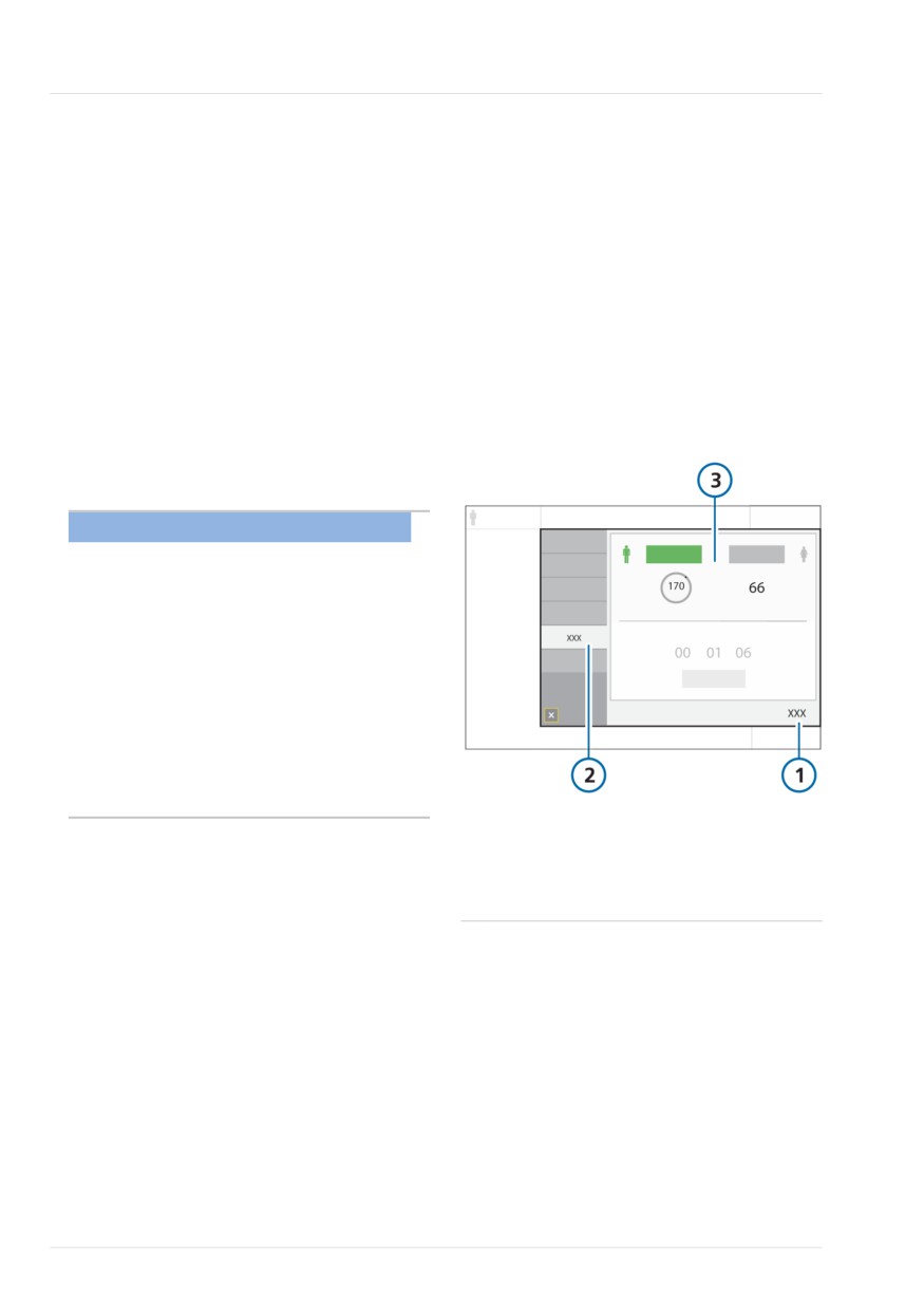
Figure 10-1. Controls > Patient window (Adult/
Ped shown)
10.2.1 Accessing patient data during
ventilation
NOTICE
Changing the patient height (Adult/Ped.)
or weight (Neonatal) automatically
adjusts the following settings based on
the recalculated IBW or updated Weight:
• Apnea backup setting (when set to
Automatic)
• Safety ventilation/Safety mode startup
values
Other settings and alarm limits are not
adjusted.
1
Controls
3
Adult/Ped: Sex and
During ventilation, the Controls > Patient
height, calculated IBW
window displays the basic patient profile,
Neonatal: Weight
including sex, height, and ventilation time
2
Patient
(Section 5.2).
When the ventilator is in Standby, the
patient controls are accessible in the
Standby window.
Note that if you are ventilating using the
Last patient setup, these controls are
greyed out and unavailable.
214
English | 10103179/02 USA
Accessing settings during ventilation
10
10.2.2 Accessing settings during
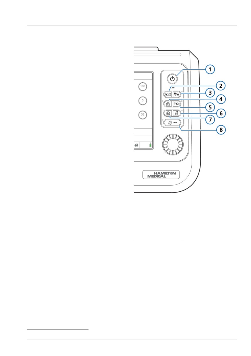
Figure 10-2. Function keys
ventilation
At any time during ventilation, you can
adjust settings, as needed. Changes are
applied immediately.
•
Touch any MMP, the SpO2 parameter
under the MMPs, or Alarms to access
the alarm limit controls.
•
Touch Controls to access the mode
controls. Some controls are also avail-
able on the right side of the main
display.
•
Touch the mode name at the top left of
the display (Figure 5-1) or the Modes
button to change the selected ventila-
tion mode.
The mode changes at the end of the
current breath cycle.
Note that you can only select the nCPAP
and nCPAP-PC modes when in Standby.
•
Touch the Patient icon or touch Con-
trols > Patient to access patient
settings.
1
Power/Standby
5
O2 enrichment
2
Day/Night68
6
Nebulizer
•
Touch the Humidifier icon to access the
Humidifier window.
3
Screen lock/
7
Print screen
unlock
•
Touch the Connectivity icon to access
the Connectivity window.
4
Manual breath
8
Audio pause
The ventilator also provides access to key
functions.
Keys on the front of the ventilator provide
access to important functions, including
entering Standby mode and pausing the
audible alarm.
When a selected function is active, the
indicator light next to the key is lit.
68 Applies only to devices with serial number > 3000.
Hamilton Medical | HAMILTON-T1 Operator's Manual
215