HAMILTON-T1. Operator's Manual (2022) - page 3
5 Specifying ventilation settings
5.3 Entering patient data
5.4 Performing the preopera-
tional check, tests, and calibra-
CAUTION
tions
Entering the correct patient data ensures
The tests and calibrations described in this
safe ventilation settings for start up,
section help verify the safety and reliability
Apnea backup, and Safety ventilation/
of the ventilator.
Safety mode.
If a test fails, troubleshoot the ventilator as
Before proceeding, review the safety
indicated or have the ventilator serviced.
information in Chapter 1.
Make sure the tests pass before you return
the ventilator to clinical use.
Specifying the correct patient data is par-
ticularly important, as the ventilator uses
The test results are stored in memory,
this data as a basis for some calculations
including when the ventilator is turned
and initial mode control settings.
off. This allows the ventilator to be
checked and kept in storage, ready for
• For the Adult/Ped patient group, the
use.
ventilator uses sex and patient height
to calculate the ideal body weight
The time and date of the last test is
(IBW).
displayed in the System > Tests & calib.
window. Ensure the last performed preop-
The following control settings are
erational test is valid for your patient.
based on IBW: Vt, Rate, T low, T high,
and TI, and Apnea backup and safety
The audible alarm is paused during calib-
settings.
ration, and for 30 seconds thereafter.
• For Neonatal patients, the ventilator
Table 5-2. When to perform tests and calibra-
uses the patient body weight.
tions
The following parameters are set based
on Weight: Vt, Rate, T low, T high, TI,
Test or calib-
When to perform
and TI max, and Apnea backup and safe-
ration
ty settings.
Preopera-
Before connecting a new
tional check
patient to the ventilator.
To enter patient data
Flow sensor/
After connecting a new
4 In the Standby window:
circuit calibra-
breathing circuit or compo-
- Adult/Ped. Specify the patient sex
tion and Leak
nent (including a flow
and height. The device calculates the
test
sensor or pressure-monitor-
patient IBW.
ing line).
- Neonatal. Specify the patient
O2 sensor
After installing a new O2
weight.
calibration, if
sensor or when a related
needed
alarm occurs.
90
English | 10103179/02 USA
Performing the preoperational check
5
Test or calib-
When to perform
5.4.1 Performing the preoperational
ration
check
CO2 sensor/
Required after connecting a
Before proceeding, review the safety
adapter zero
CO2 sensor or when a rela-
information in Chapter 1.
calibration
ted alarm occurs.
(mainstream/
For details about performing the preoper-
Recommended after switch-
sidestream)
ational check with neonatal ventilation,
ing between different air-
see Section 6.2.
way adapter types.
Alarm tests
As desired
When to perform
Before connecting a new patient to the
To access tests and calibration functions
ventilator.
1. Do either of the following:
To perform the preoperational check
- Touch System > Tests & calib.
1. Use a setup as described in Table 5-3.
- In the Standby window, touch Preop
2. Perform all of the steps in Table 5-4.
check.
2. Touch the button for the desired oper-
To ensure that the ventilator functions
ation.
according to specifications on your
patient, perform the preoperational check
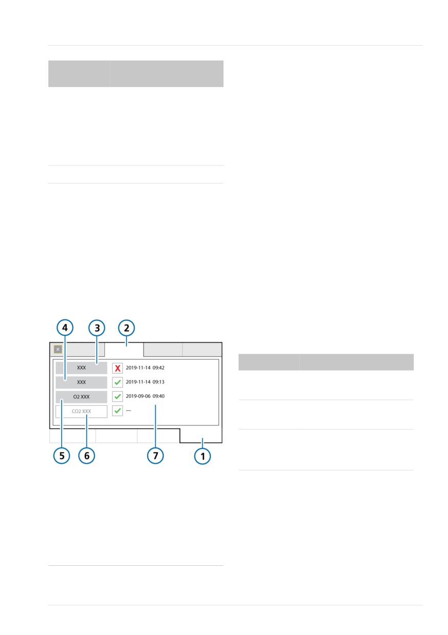
Figure 5-2. System > Tests & calib window
using the breathing circuit that will be
used on the patient.
Table 5-3. Test breathing circuit setup
Component
Specification
Breathing cir-
Adult/pediatric, ID10 to ID22
cuit
Flow sensor
Adult/pediatric, with calibra-
tion adapter
Test lung
Demonstration lung, 2 liter,
with adult ET tube between
flow sensor and lung
1
System
5
O2 sensor
2
Tests & calib
6
CO2 sensor
3
Leak test
7
Time and date of
(shown uncali-
last test/calibration
brated)
4
Circuit or Flow sensor, depending on
selected mode
Hamilton Medical | HAMILTON-T1 Operator's Manual
91
5 Specifying ventilation settings
Table 5-4. Preoperational check, overview
Corrective action
Do or observe…
Verify ...
indicates the component is calibrated
and ready. indicates the calibration was
1
Connect ventilator to primary power
and an oxygen supply.
unsuccessful.
2
Assemble the
The breathing cir-
If the ventilator does not pass the preoper-
patient breath-
cuit is assembled
ational check, have it serviced.
ing circuit.
correctly.
5.4.2 Performing the breathing circuit
3
Turn on the
During the self test,
ventilator.
the alarm lamp
Leak test
flashes yellow and
Before proceeding, review the safety
red in sequence.
information in Chapter 1.
4
With the ventila-
The System > Tests
To perform the Leak test
tor in Standby,
& calib window
touch Preop
opens.
1.
Set up the ventilator for ventilation,
check in the
complete with breathing circuit and
Standby
flow sensor.
window.
2.
Touch System > Tests & calib.
5
Perform the
The test passes. See
3.
Touch Leak test.
Leak test.
Section 5.4.2.
The text Disconnect patient is now
6
Calibrate the
The calibration is
displayed.
flow sensor.
successful. See
4.
Disconnect the breathing circuit at the
Section 5.4.3.
patient side of the flow sensor. Do not
block the open end of the flow
7
If necessary, run
The calibration is
the O2 sensor
successful. See
sensor.
calibration.
Section 5.4.4.
The text Block breathing circuit is now
displayed.
8
If necessary, run
The zero calibration
the CO2 sensor
is successful. See
5.
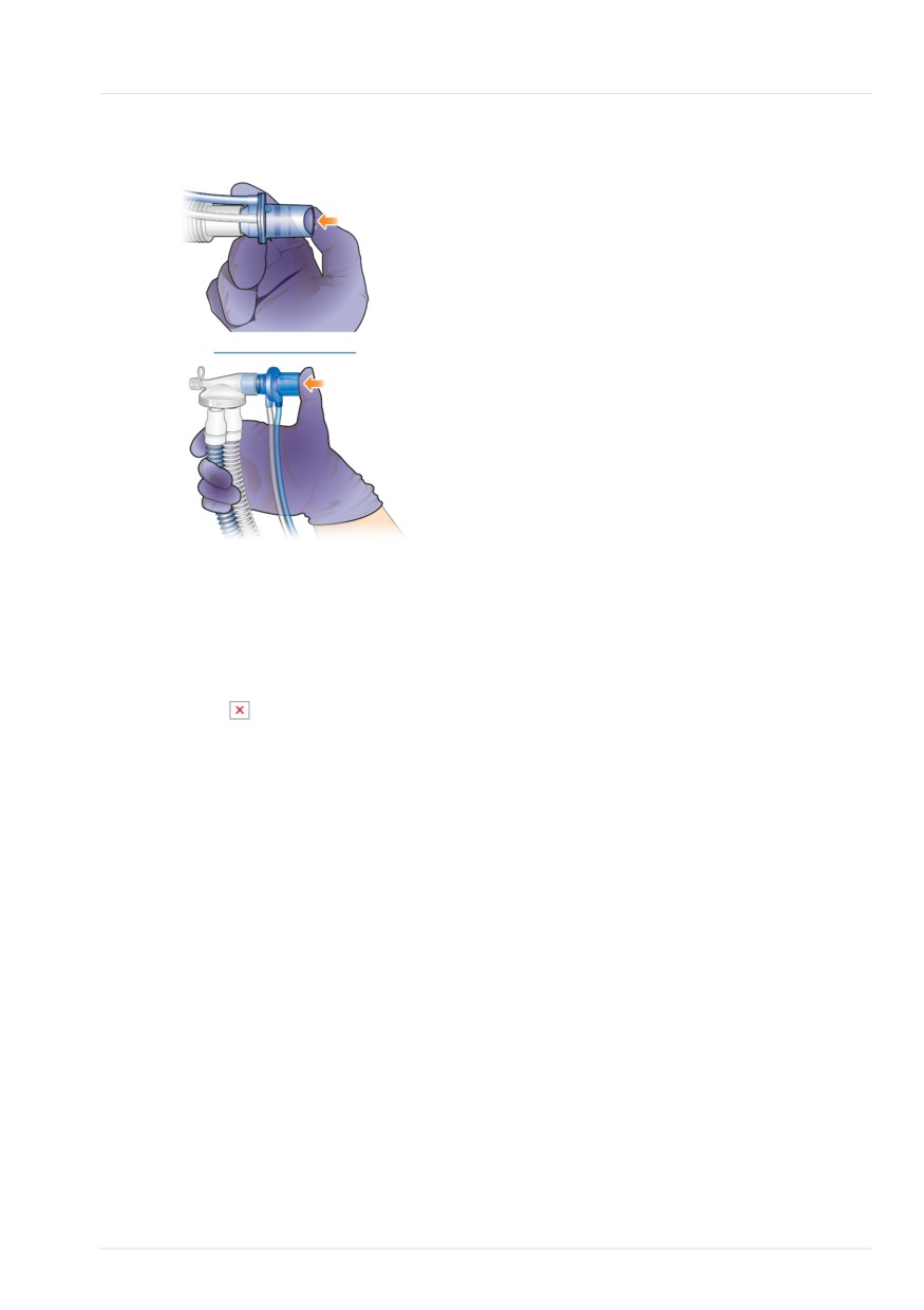
Block the opening (wearing a glove is
zero calibration.
Section 5.4.5.
recommended). See Figure 5-3.
Ensure the opening is fully blocked.
9
Generate test
The corresponding
Failure to do so may result in test fail-
alarms.
alarm message is
ure.
displayed in the
message bar. See
The text Reconnect breathing circuit is
Section 5.4.6.
now displayed.
Note that patient
6.
Connect the patient.
alarms are sup-
7.
When the test is complete, verify that
pressed in Standby.
there is a checkmark in the Leak
test checkbox.
92
English | 10103179/02 USA
Calibrating the adult/pediatric flow sensor
5
Figure 5-3. Block the flow sensor opening when
5.4.3 Calibrating the adult/pediatric
prompted
flow sensor
This calibration checks and resets the
calibration points specific to the flow
sensor in use, and measures the circuit
resistance. The measured value determines
the required resistance compensation
during ventilation.
Ensure you are using the correct flow
sensor for the selected patient group. If
there is a mismatch, calibration fails.
For details about calibrating a neonatal
flow sensor, see Section 6.2.1.
When to perform
After connecting a breathing circuit or
component.
To cancel the test while it is in progress
Flow sensor calibration involves three
4 Touch Leak test again.
components:
In case of test failure
• Flow sensor
• Component in the breathing circuit
If the test fails,
is displayed in the Leak
directly following the flow sensor
test checkbox.
Ensure that you have performed all steps
• Calibration adapter
of the test correctly. If so, perform the
To calibrate an adult/pediatric flow sensor
following checks, repeating the Leak test
after each one, until the test is successful:
1. Calibrate the flow sensor in Standby,
with no patient connected.
• Check the breathing circuit for a dis-
connection between the ventilator and
2. Connect the flow sensor to the
the flow sensor, or for other large leaks
breathing circuit (Figure 5-4).
(for example, breathing circuit, humidi-
3. Connect the next component in the
fier).
circuit to the flow sensor (Figure 5-5).
• Check that the flow sensor and expira-
Depending on your setup, this could
tory valve set are properly seated.
be, for example, an HMEF, nebulizer,
CO2 sensor, or the flex tube.
• If the test still fails, replace the expira-
Do not connect any more components
tory valve set.
at this time. You will be prompted to
• If the test still fails, replace the breath-
connect the calibration adapter once
ing circuit.
the calibration process starts.
If the problem still persists, have the venti-
lator serviced.
Hamilton Medical | HAMILTON-T1 Operator's Manual
93
5 Specifying ventilation settings
4.
In the Standby window, touch Preop
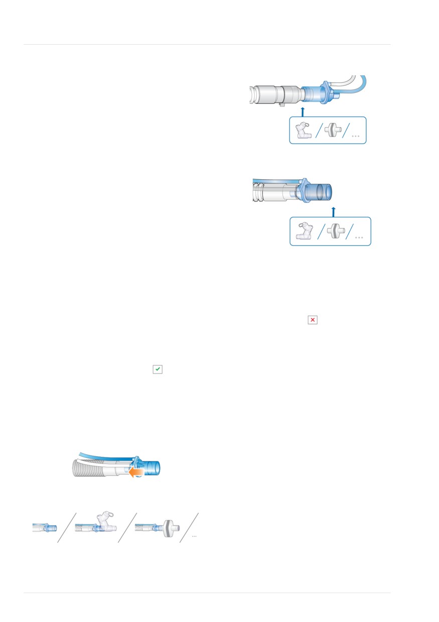
Figure 5-6. Attach adapter, flip components
check.
The System > Tests & calib window is
displayed.
5.
Touch Flow sensor.
A help guide is shown on the display,
providing an overview of the calibra-
tion process.
Figure 5-7. Flip components, remove adapter
6.
Touch Start to begin calibration.
To close the guide without starting
calibration, touch Cancel.
7.
When prompted on the display, attach
the calibration adapter to the compo-
nent connected to the flow sensor
and flip all three of them together
180° so the adapter is directly con-
To cancel an ongoing calibration
nected to the breathing circuit (Figure
5-6).
4 Touch Flow sensor again.
8.
When prompted, flip the flow sensor/
In case of calibration failure
component/adapter 180° again, so
the flow sensor is directly connected
If the calibration fails,
is displayed in
to the breathing circuit, and remove
the Flow sensor checkbox.
the calibration adapter (Figure 5-7).
Ensure that you have performed all steps
9.
When calibration is complete, verify
of the test correctly. If so, perform the
that there is a checkmark
in the
following checks, repeating the calibration
Flow sensor checkbox.
after each one, until calibration is success-
ful:
10. When successful, finish assembling
the breathing circuit, and continue
• Ensure that the flow sensor is appropri-
with other tests or ventilation.
ate for the selected patient group.
Figure 5-4. Connect the flow sensor
• Check the breathing circuit for a dis-
connection between the ventilator and
the flow sensor, or for other large leaks
(for example, breathing circuit, humidi-
fier).
Figure 5-5. Connect the next component
• Check that the flow sensor and expira-
tory valve set are properly seated.
94
English | 10103179/02 USA
Calibrating the O2 sensor
5
• If the calibration still fails, replace the
2. Touch System > Tests & calib.
flow sensor.
3. Touch O2 sensor.
• If the calibration still fails, replace the
4. When calibration is complete, verify
expiratory valve membrane.
that there is a checkmark
in the O2
• If the calibration still fails, replace the
sensor checkbox.
expiratory valve set.
Table 5-5. Oxygen concentration during O2
If the problem persists, have the ventilator
sensor calibration
serviced.
Standby or
Gas source
Set
active ventila-
connection
Oxygen
5.4.4 Calibrating the O2 sensor
tion
status
to ...
100% oxygen calibration34
CAUTION
Standby
HPO
any
When using an oxygen supply < 99%
Connected
(HPO) or low pressure oxygen (LPO), cali-
Active
HPO
> 21%
brate the O2 cell at 21%. This informa-
ventilation35
Connected
tion is displayed in the Calibration
window.
21% oxygen calibration
When the oxygen supply is less than 99%,
NOTICE
you must disconnect the oxygen supply
before calibration.
When using LPO, disconnect the oxygen
supply during calibration.
Standby
LPO
21%
Disconnected
Calibrate the O2 sensor if either of the
following occur:
Active ventila-
HPO
21%
tion
Connected
•
is displayed in the O2 sensor check-
Active
LPO
21%
box (Figure 5-2)
ventilation
Disconnected
• The O2 sensor calibration needed alarm
is generated.
To perform O2 sensor calibration
1. Using the information in Table 5-5, set
the Oxygen control as appropriate to
calibrate the sensor using either 21%
or 100% oxygen.
For example, to calibrate during active
ventilation with 100% oxygen, ensure
the Oxygen control is set to 22% or
higher.
34 Calibrating at 100% improves the stability of measurements at higher oxygen concentrations during use.
35 Only for adult/pediatric patients.
Hamilton Medical | HAMILTON-T1 Operator's Manual
95
5 Specifying ventilation settings
In case of calibration failure
Zero calibration requirements for main-
stream CO2 sensors
If the calibration fails, a red
is displayed
Perform a zero calibration in the following
in the O2 sensor checkbox.
cases:
Perform the following checks, repeating
• With the first use of the sensor
the calibration after each one, until calib-
ration is successful:
• When changing between airway
adapter types (for example, from single
• Ensure a Hamilton Medical O2 sensor is
use to reusable)
installed.
• When the CO2 calibration needed alarm
• If the second calibration attempt fails,
is generated
replace the O2 sensor.
Zero calibration requirements for side-
If the problem persists, have the ventilator
stream CO2 sensors
serviced.
You only need to perform a zero calibra-
tion with sidestream CO2 sensors when
5.4.5 Performing a zero calibration of
the CO2 calibration needed alarm is gene-
the CO2 sensor/adapter
rated.
Before proceeding, review the safety
To ensure all CO2 is dissipated, wait 2
information in Chapter 1.
minutes to perform the zero calibration
after removing the adapter from the
CAUTION
patient’s airway.
• Always perform zero calibration with
To perform the zero calibration of the CO2
the CO2 sensor (mainstream) or CO2
sensor/adapter (mainstream) and sensor/
module (sidestream) connected to the
module (sidestream)
airway adapter.
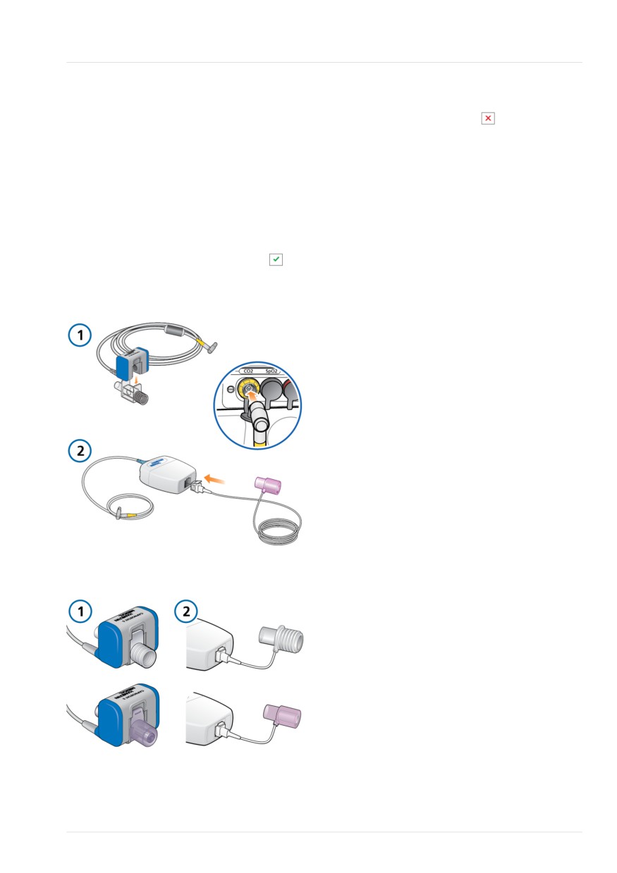
1. Connect the CO2 adapter (1 main-
• Be sure NOT to cover both ends of
stream) or the CO2 module (2 side-
the airway adapter with your fingers.
stream) to the CO2 port on the ventila-
tor (Figure 5-8), and ensure CO2
The CO2 adapter zero calibration compen-
monitoring is enabled.
sates for optical differences between air-
Wait at least 2 minutes for the device
way adapters and for sensor drift.
to warm up.
Note that the CO2 sensors are calibrated
2. Disconnect the CO2 sensor/adapter
at the factory; you only need to zero the
from the breathing circuit.
adapters as described next.
See Figures 4-4 and 4-6 for the sensor
location in the breathing circuit.
3. Attach the CO2 sensor to the adapter
(1 mainstream) or snap it into the CO2
module (2 sidestream) (Figure 5-9).
96
English | 10103179/02 USA
Testing the alarms
5
Keep these components away from all
In case of zero calibration failure
sources of CO2, including the patient's
and your own exhaled breath, as well
If the zero calibration fails,
is displayed
as the ventilator exhaust port.
in the CO2 sensor checkbox.
4. Touch System > Tests & calib.
Perform the following checks, repeating
the zero calibration after each one, until it
5. Touch CO2 sensor.
is successful:
Do not move the components during
• Check the airway adapter and clean if
calibration.
necessary.
6. When the zero calibration is complete,
• If the zero calibration still fails, ensure
verify that there is a checkmark
in
there is no source of CO2 near the air-
the CO2 sensor checkbox.
way adapter.
Figure 5-8. Connecting the components
• If the zero calibration still fails, connect
a new adapter.
• If the zero calibration still fails, connect
a new CO2 sensor (mainstream) or
CO2 module (sidestream).
If the problem persists, have the ventilator
serviced.
5.4.6 Testing the alarms
During ventilator startup, the HAMILTON-
T1 performs a self-check that also verifies
proper alarm function, including genera-
tion of an audible alarm sound. You are
not required to perform additional alarm
Figure 5-9. Sensor and adapter connected for
tests.
calibration
If desired, you can test any adjustable
alarm by manually changing the set limit
such that the ventilator exceeds or fails to
reach the set limit, thereby generating the
associated alarm. For details on setting
alarm limits, see Section 5.7.
For any tests, use a demonstration lung
assembly as described in Section 5.4.1.
Hamilton Medical | HAMILTON-T1 Operator's Manual
97
5 Specifying ventilation settings
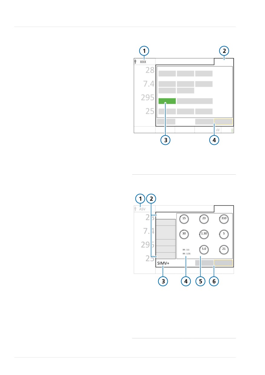
Figure 5-10. Modes window, changing modes
5.5 Selecting the ventilation
mode
The active ventilation mode is displayed at
the top left corner of the display together
with the selected patient group.
When first starting to ventilate a patient,
the mode associated with the selected
Quick setup is pre-selected. You can
change it, if needed.
For details about each of the modes, see
Chapter 7.
To select a mode
1.
Do either of the following (see Figure
5-10):
1
Active mode,
3
New mode
patient group
- Touch the mode name (1) at the top
left of the display.
2
Modes
4
Cancel/Confirm
- Touch Modes (2) at the top right of
the display.
Figure 5-11. Controls window, changing modes
2.
In the Modes window, touch the
desired mode, then touch Confirm.
The Confirm button is only displayed
after you select a different mode in
the window.
The Controls window opens.
3.
Review and, if needed, adjust the
control settings (Figure 5-12), then
touch Confirm to enable the new
mode.
After you touch Confirm, the mode
changes at the end of the current
breath cycle.
Without confirmation, the window
1
Active mode,
4
Values depending
closes after a short time and the cur-
patient group
on mode
rently active mode remains in place.
2
Tabs: Basic, More,
5
Controls for new
Apnea, Patient,
mode
SpeakValve
3
New mode
6
Cancel/Confirm
98
English | 10103179/02 USA
Reviewing and adjusting ventilation settings
5
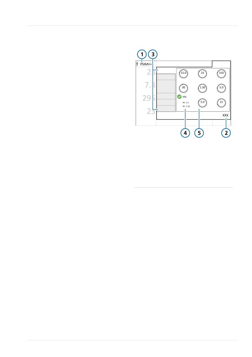
Figure 5-12. Controls window, settings for
5.6 Reviewing and adjusting
active mode
ventilation settings
You specify ventilation settings in the Con-
trols window tabs: Basic, More, Apnea.
The Patient tab provides access to patient
data during ventilation.
Which tabs are available depends on
which mode is selected, as well as
whether you are in Standby or active venti-
lation.
In addition, the window changes slightly
depending on whether you are changing
settings for the active mode or you are
changing modes.
1
Active mode,
4
Values depending
To change the control settings for the
patient group
on mode (I:E, TE,
active mode
TI)
1. Touch Controls, and select and adjust
2
Controls
5
Mode controls
settings as needed. See Figure 5-12.
3
Tabs: Basic, More, Apnea, Patient, Speak-
The change takes effect immediately.
Valve
2. Touch More to enable/disable Sigh, if
needed.
3. If applicable, touch Apnea and select
or deselect Backup as needed.
4. If you need to change basic patient
data, touch Patient and adjust settings
as needed. See Section 5.3.
Hamilton Medical | HAMILTON-T1 Operator's Manual
99
5 Specifying ventilation settings
5.6.1 About Plimit and related pres-
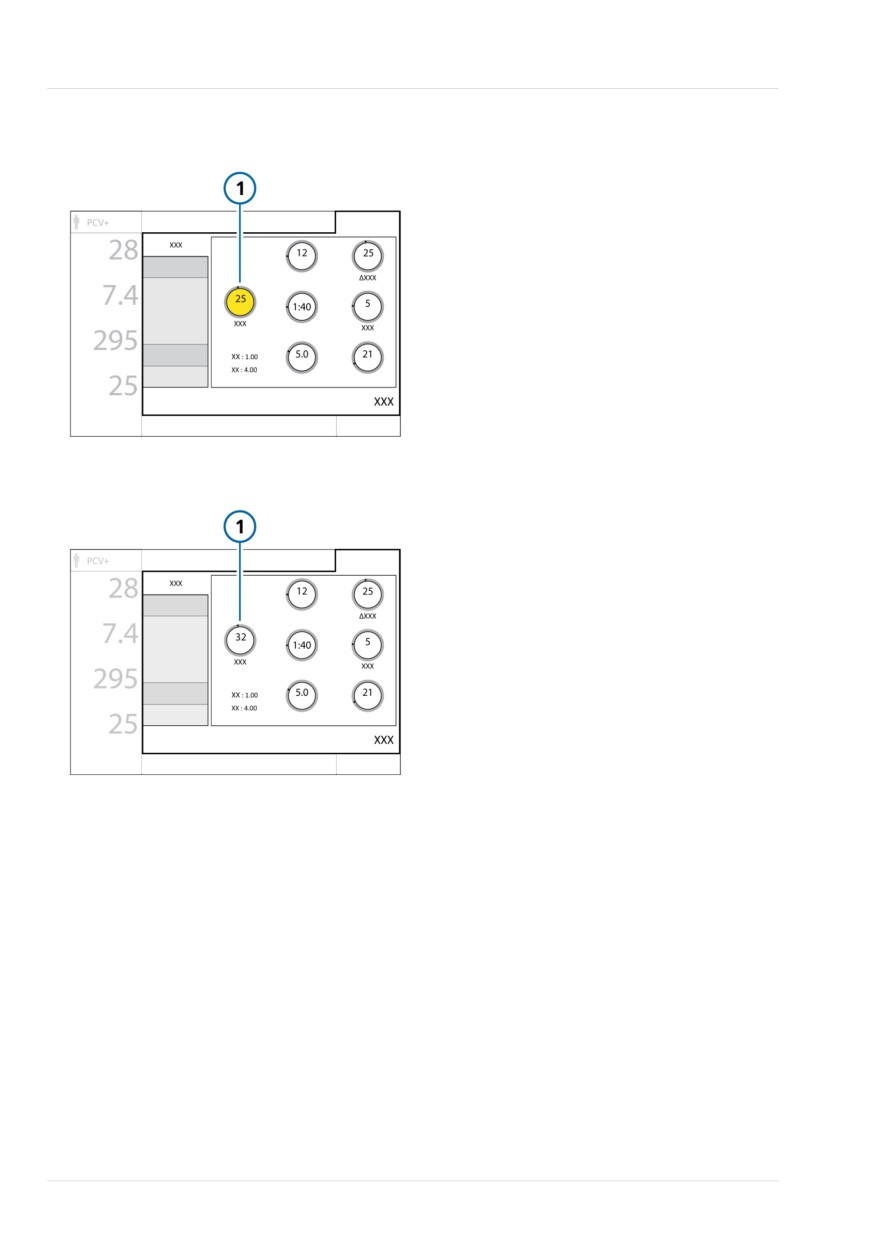
The following examples illustrate each of
sure-control settings
these cases.
The pressure limit setting (Plimit) defines
Example 1: Pressure control setting adjust-
ments exceed Plimit
the maximum allowed pressure to apply
during ventilation. This setting is available
Assume the control parameters are set as
in the Controls > Basic window (Figure
follows:
5-12).
Plimit = 32 cmH2O
Furthermore, the Plimit control setting is
ΔPcontrol = 25 cmH2O
directly related to the high Pressure alarm
PEEP/CPAP = 5 cmH2O
limit, in that changing one of these
Total inspiratory pressure = 30 cmH2O
settings automatically changes the other:
(ΔPcontrol + PEEP/CPAP in this example)
The high Pressure alarm limit is always
The total inspiratory pressure of
10 cmH2O greater than Plimit.
30 cmH2O is below Plimit. The ventilator
Depending on the selected mode, the
delivers the total inspiratory pressure as
following control parameters can be used
set.
to set pressure: ΔPcontrol, ΔPinsp, ΔPsup-
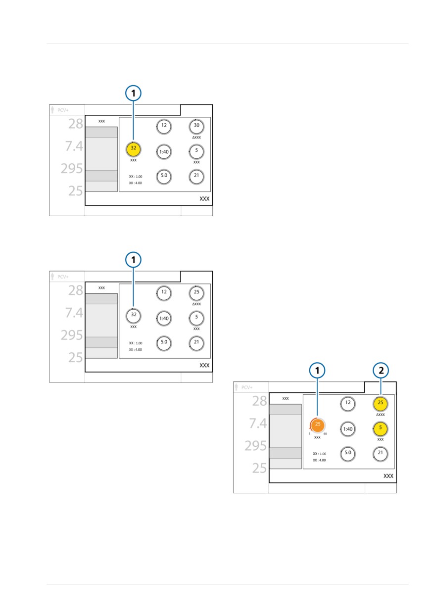
If you increase ΔPcontrol to 30 cmH2O,
port, or P high.
the total inspiratory pressure, which is
The total inspiratory pressure to be applied
now 35 cmH2O, exceeds Plimit and the
is defined as follows:
following occurs:
• ΔPcontrol + PEEP/CPAP
1.
Plimit (1 in Figure 5-13) is highlighted
in yellow, indicating that total inspira-
• ΔPsupport + PEEP/CPAP
tory pressure exceeds Plimit
• ΔPinsp + PEEP/CPAP
2.
Either decrease the pressure control
settings or increase Plimit to ensure
• P high36
that Plimit is equal to or greater than
If the total inspiratory pressure exceeds
the total inspiratory pressure setting.
Plimit, the ventilator only delivers pressure
When Plimit (1 in Figure 5-17) meets
equal to Plimit. The ventilator cannot
this condition, it is no longer high-
deliver the set pressure and the Pressure
lighted in yellow.
limitation alarm is generated. When this
conflict occurs, the Plimit control is high-
lighted in yellow in the Controls window
and the Check Plimit alarm is generated.
During active adjustment, you may see the
pressure or Plimit controls turn yellow,
indicating that total inspiratory pressure
exceeds Plimit with the proposed settings.
Adjust pressure-related settings to resolve
the conflict.
36 In DuoPAP and APRV modes, P high defines the total inspiratory pressure to be delivered. PEEP/CPAP does not need to be accounted
for.
100
English | 10103179/02 USA
About Plimit and related pressure-control settings
5
Figure 5-13. Total inspiratory pressure exceeds
If you decrease Plimit to 25 cmH2O, the
Plimit
total inspiratory pressure of 30 cmH2O
exceeds Plimit and the following occurs:
1. The currently active Plimit control that
you are adjusting (1 in Figure 5-15) is
shown in orange.
The pressure controls are highlighted
in yellow (2) if the total inspiratory
pressure exceeds Plimit, indicating
there is a conflict.
2. Upon confirming the new Plimit
setting, Plimit (1 in Figure 5-16) is
highlighted in yellow, indicating there
is a conflict. The pressure controls
Figure 5-14. Total inspiratory pressure no longer
return to their default color.
exceeds Plimit
3. Either decrease the pressure control
settings or increase Plimit to ensure
that Plimit is equal to or greater than
the total inspiratory pressure setting.
When Plimit (1 in Figure 5-17) meets
this condition, it is no longer high-
lighted in yellow.
Figure 5-15. Plimit control is active, total
inspiratory pressure exceeds Plimit
Example 2: Plimit setting adjustment is
below total inspiratory pressure
Assume the control parameters are set as
follows:
Plimit = 32 cmH2O
ΔPcontrol = 25 cmH2O
PEEP/CPAP = 5 cmH2O
Total inspiratory pressure = 30 cmH2O
(ΔPcontrol + PEEP/CPAP in this example)
The total inspiratory pressure of
30 cmH2O is below Plimit. The ventilator
delivers the total inspiratory pressure as
set.
Hamilton Medical | HAMILTON-T1 Operator's Manual
101
5 Specifying ventilation settings
Figure 5-16. Total inspiratory pressure still
Apnea backup ventilation enabled
exceeds Plimit
Apnea backup provides ventilation after the
apnea time passes with no breath
attempts detected. The apnea time is set
in the Alarms window using the Apnea
time control.
When this occurs, the ventilator automati-
cally and immediately switches into Apnea
backup ventilation.
It generates a low-priority alarm, displays
the alarm Apnea ventilation, and provides
ventilation using the settings specified in
Section 7.1.2.
Figure 5-17. Total inspiratory pressure no longer
When set to Automatic, the control setting
exceeds Plimit
for the Apnea backup mode depends on
the IBW (or weight for neonates) of the
patient.
To change the Apnea backup control
settings
1. Touch Controls > Apnea.
2. Clear the Automatic checkbox.
The settings controls are enabled.
3. Change the values as desired.
The changes take effect immediately.
5.6.2 About Apnea backup ventilation
Before proceeding, review the safety
information in Chapter 1.
The HAMILTON-T1 provides Apnea backup
ventilation, a mechanism that minimizes
possible patient injury due to apnea or
cessation of respiration. Apnea backup is
available in the following modes: APVsimv,
SPONT, DuoPAP, APRV, and NIV.
102
English | 10103179/02 USA
Setting alarm limits
5
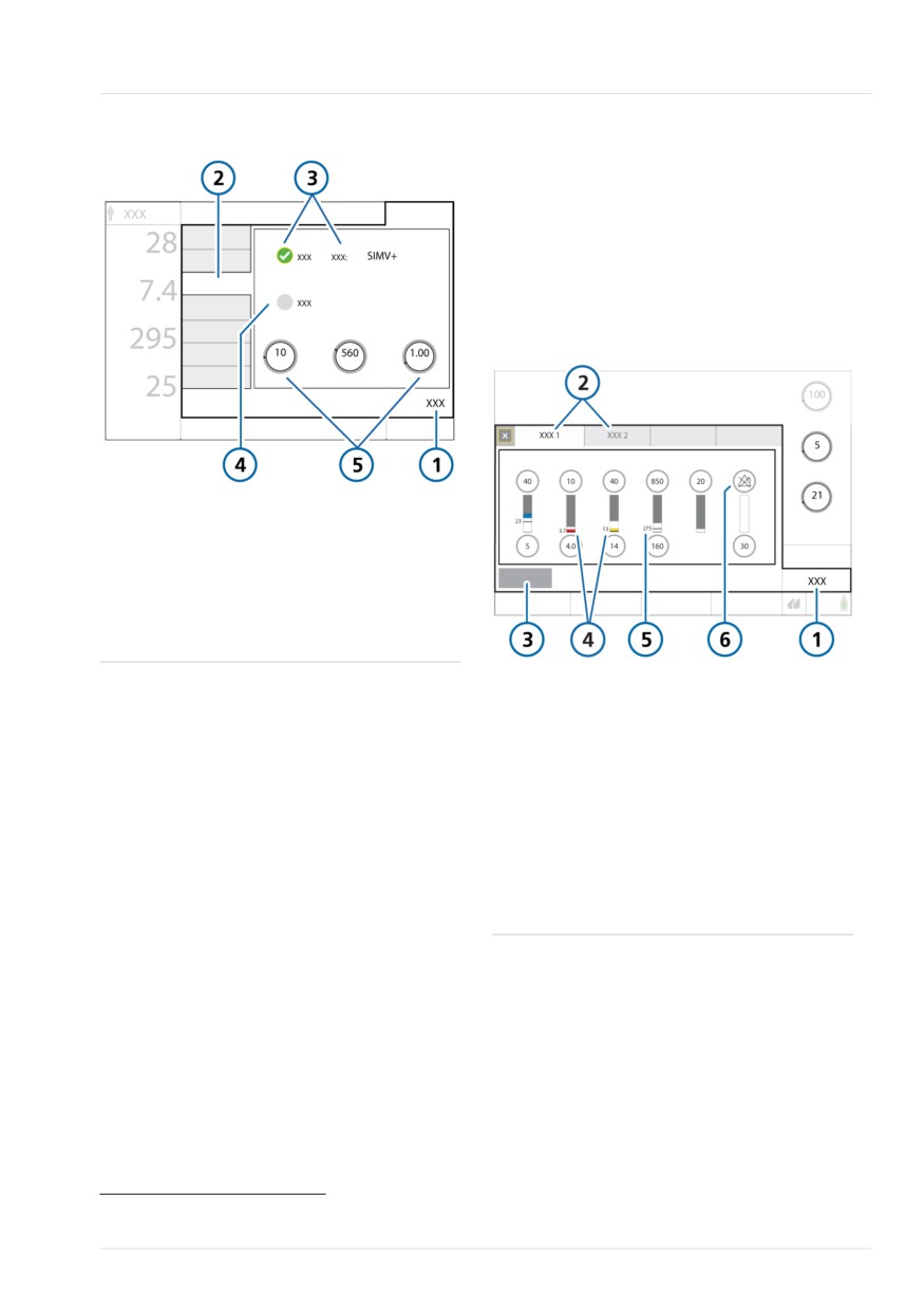
Figure 5-18. Controls > Apnea window
5.7 Setting alarm limits
Before proceeding, review the safety
information in Chapters 1 and 9.
You can access the Alarms window and
change alarm settings at any time, with-
out affecting ventilation.
Figure 5-19. Alarms > Limits 1 window
1
Controls
4
Automatic check
box
2
Apnea
5
Control settings cor-
responding to the
mode
3
Backup check box and mode
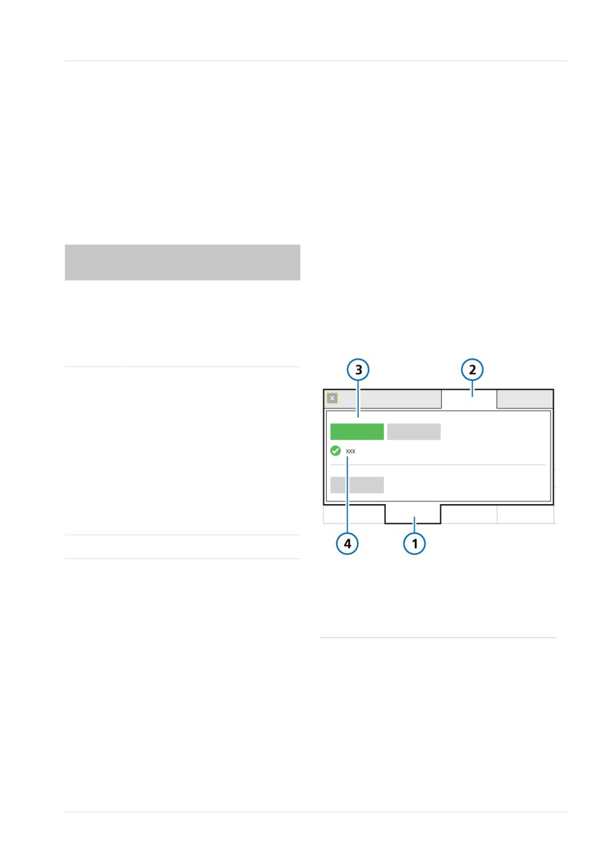
1
Alarms
4
Red or yellow bar
If the patient triggers two consecutive
(depending on alarm
breaths, the ventilator reverts to ventila-
priority) indicates the
tion in the original support mode and at
monitored value is
the original settings, and displays the mes-
out of range
sage, Apnea ventilation ended.
2
Limits 1, 2
5
Current monitored
value
Once Apnea backup ventilation is enabled
or disabled, it retains this status in all
3
Auto37, 38
6
Alarm Off symbol
applicable modes. Apnea backup ventila-
when an alarm limit
tion requires no clinician intervention,
is set to Off
although you can freely change the mode
during Apnea backup ventilation, either
switching to a new mode or accepting the
backup mode as the new mode.
Apnea backup ventilation disabled
When Apnea backup is disabled, the high-
priority Apnea alarm is generated when
apnea occurs and there is no patient trig-
ger within the operator-set interval.
37 Not available during neonatal ventilation.
38 Not available in all markets.
Hamilton Medical | HAMILTON-T1 Operator's Manual
103
5 Specifying ventilation settings
To review and adjust alarms
1.
Either touch the Alarms button or
touch an MMP on the left of the
display.
The Alarms > Limits 1 window is
displayed (Figure 5-19).
2.
To set an alarm limit individually,
touch the alarm control and adjust the
value.
Repeat for any other alarm.
3.
Access additional alarm settings by
touching the Limits 2, and if used,
Limits 3 tabs.
The ventilator displays
(Alarm Off
symbol) when an alarm limit is set to
Off.
For details about the Oxygen alarm
limits, see Section 5.7.1.
4.
To set alarm limits automatically,
touch Auto38,39 in the Limits 1 window.
Selecting Auto automatically sets
alarm limits around the current
monitoring parameter values except
for the Vt and Apnea alarm limits40.
These alarm limits remain unchanged,
and must be set manually to the
desired level.
Note that some automatic settings are
not appropriate under all clinical con-
ditions. Check the validity of the
settings as soon as possible.
5.
Close the window.
The following table briefly describes each
of the adjustable ventilator alarms. Addi-
tional details are available in Table 15-13.
For SpO2-related alarms, see the Pulse
Oximetry Instructions for Use.
39 Not available during neonatal ventilation.
40 SpO2-related alarms are also not automatically set.
104
English | 10103179/02 USA
Setting alarm limits
5
Table 5-6. Adjustable alarms
Alarm
Definition
Apnea time
The maximum time allowed from the beginning of one inspira-
tion to the beginning of the next inspiration.
If the patient does not trigger a breath during this time:
• A low-priority alarm sounds if Apnea backup is enabled.
Apnea ventilation begins.
• A high-priority alarm sounds if Apnea backup is disabled
Not applicable in nCPAP or nCPAP-PC modes, or during
HiFlowO2.
ExpMinVol (low and high)
Low and high expiratory minute volume. If either limit is
reached, a high-priority alarm is generated.
Not applicable in nCPAP or nCPAP-PC modes.
For alarm details when using a speaking valve, see Table 10-1.
During CPR ventilation, alarm limits are automatically set to
their minimum and maximum allowed limits. See Table 15-13.
Flow
Only active in nCPAP and nCPAP-PC modes.
The High Flow alarm is generated when the limit is reached.
fTotal (low and high)
Low and high monitored total breath rate (fTotal), including
both spontaneous and mandatory breaths. If either limit is
reached, a medium-priority alarm is generated.
Not applicable in nCPAP or nCPAP-PC modes.
During CPR ventilation, alarm limits are automatically set to
their minimum and maximum allowed limits. See Table 15-13.
Oxygen (low and high)
Low and high monitored oxygen concentration (Oxygen). If
either limit is reached, a high-priority alarm is generated.
Applies only when low-pressure oxygen is used or the Set
Oxygen alarm limits manually checkbox is selected with HPO.
PetCO2 (low and high)
Low and high monitored PetCO2. If either limit is reached, a
medium-priority alarm is generated.
During CPR ventilation, alarm limits are automatically set to
their minimum and maximum allowed limits. See Table 15-13.
Hamilton Medical | HAMILTON-T1 Operator's Manual
105
5 Specifying ventilation settings
Alarm
Definition
Pressure (low and high)
Low and high monitored pressure at the patient airway (Ppeak).
If the high Pressure limit is reached or the device fails to reach
the low Pressure limit, a high-priority alarm is generated.
When pressure reaches the Plimit setting (high Pressure limit
minus 10 cmH2O), inspiratory pressure is limited to this setting;
the pressure is not increased further.
If the delivered pressure is the same as the set high Pressure
alarm limit, the device aborts the breath and reduces the pres-
sure to PEEP level.
Sigh breaths are an exception to this rule. In this case, the
ventilator may apply inspiratory pressure up to 3 cmH2O below
the high Pressure alarm limit.
Vt (low and high)
Low and high expiratory tidal volume, for two consecutive
breaths. If either limit is reached, a medium-priority alarm is
generated.
When the delivered Vt is > 1.5 times the set upper Vt alarm
limit, the Inspiratory volume limitation alarm is generated. In this
case, the device aborts the breath and reduces the pressure to
PEEP level.
The APV controls reduce the pressure for the next breath by
3 cmH2O.
During CPR ventilation, alarm limits are automatically set to
their minimum and maximum allowed limits. See Table 15-13.
106
English | 10103179/02 USA
About the Oxygen alarm limits
5
5.7.1 About the Oxygen alarm limits
To enable manual adjustment of Oxygen
alarm limits in HPO mode
How the device sets the Oxygen alarm
1. Touch Tools > Utilities.
limits depends on the gas source used
(LPO or HPO) and associated option
2. Select HPO mode as the gas source.
settings.
3. To set the Oxygen alarm limits your-
Oxygen alarm limits are set as follows:
self, touch the Set Oxygen alarm limits
manually checkbox.
Table 5-7. Setting Oxygen alarm limits in LPO
When selected, the Oxygen alarm limit
and HPO modes
controls are enabled in the Alarms
window. You can now set the limits as
Gas
Setting Oxygen alarm limits
desired.
source
4. To have the limits set automatically,
LPO
Always manually. The Oxygen
ensure the checkbox is clear.
alarm limit controls are enabled
in the Alarms window and are
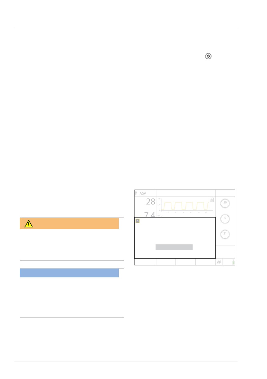
Figure 5-20. Setting Oxygen alarm limits manu-
manually adjusted, as appropri-
ally with HPO
ate.
HPO
By default, automatically. The
Oxygen high/low alarms are, by
default, automatically set to the
current Oxygen setting ± 5 (abso-
lute value). The Oxygen alarm
limit controls are disabled in the
Alarms window.
To set them manually, select the
Set Oxygen alarm limits manually
option, as described next.
The minimum lower alarm limit is 18%.
1
Tools
3
Gas source: HPO mode
Setting the oxygen alarm limits manually
2
Utilities
4
Set Oxygen alarm limits
reduces the alarms, for example, when
manually checkbox
using an oxygen supply < 99%.
selected
Hamilton Medical | HAMILTON-T1 Operator's Manual
107
5 Specifying ventilation settings
To stop ventilation and place the ventilator
5.8 Starting ventilation
in Standby
Before starting ventilation, review the
1. Press and quickly release
(Power/
patient information in the Standby
Standby) while the ventilator is turned
window and ensure it is correct.
on (Figure 10-2).
To start ventilation
The Activate Standby window opens
(Figure 5-21).
4 Do one of the following:
- In Standby, press the Power/Standby
2. Touch Activate standby.
key.
The Standby window opens (Figure
- In Standby, touch Start ventilation.
5-22).
- Using the P&T knob, move the
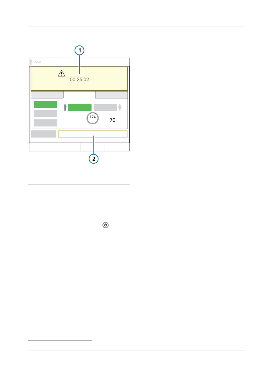
While in Standby, the window shows the
cursor to the Start ventilation button,
elapsed time the ventilator has been in
and press the P&T knob.
Standby.
When using HiFlowO2, the button is
Note that, if another window is open on
labeled Start therapy.
the display, the elapsed time appears in a
When CPR ventilation is on, the
small yellow box on the left side of the
button is labeled Start CPR.
Standby window.
Ventilation starts.
Figure 5-21. Activate Standby window
5.9 Stopping ventilation
(Standby)
WARNING
Standby
No ventilation delivered to the patient.
When in Standby, the ventilator does not
Deactivate humidifier during Standby.
automatically resume ventilation when
Activate standby
the patient is reconnected. You must
manually restart ventilation.
NOTICE
• Patient alarms are suppressed in
Standby.
• Acoustic patient alarms are sup-
pressed for 1 minute after starting
ventilation from Standby.
Standby is a waiting mode that lets you
maintain ventilator settings while the
ventilator is not performing any ventilatory
functions.
108
English | 10103179/02 USA
About the control parameters
5
Figure 5-22. Standby window
5.10 About the control para-
meters
Table 5-8 provides a brief description of
the ventilator’s control parameters, also
referred to as control settings. You can
review and adjust these settings in various
locations, depending on their function.
Table 15-9 in the Specifications chapter
provides the control parameter ranges and
default settings, including accuracy.
For a comparison of Hamilton Medical
ventilation-related terminology with ISO
19223:2019, see Section 15.5.
1
Elapsed time in
2
Start ventilation41
Standby
To end Standby and start ventilation
4 Do either of the following:
- Touch Start ventilation41.
- Press and quickly release
Ventilation resumes with the previous
settings.
To enter Standby and stop ventilation
1. Press the Power/Standby key.
2. In the confirmation window, touch
Activate standby.
The device enters Standby (Figure 5-1). The
yellow counter shows the time elapsed in
Standby.
41 When HiFlowO2 is selected: Start therapy; when CPR ventilation is on: Start CPR.
Hamilton Medical | HAMILTON-T1 Operator's Manual
109
5 Specifying ventilation settings
Table 5-8. Control parameters, defined
Parameter
Definition
%MinVol
Percentage of minute volume to be delivered in ASV mode. The ventila-
tor uses the %MinVol, Pat. height, and sex settings to calculate the
target minute ventilation.
Add 20% per degree of body temperature > 38.5°C (101.3°F).
Apnea backup
A function that provides ventilation after the adjustable apnea time
passes without breath attempts.
If Automatic is enabled, control parameters are calculated based on the
patient's IBW (Adult/Ped patient group) or Weight (Neonatal patient
group).
Applies in APVsimv, SPONT, DuoPAP, APRV, and NIV modes.
Be sure to review the safety information in Chapter 1.
ETS
ETS (expiratory trigger sensitivity) is the percent of peak inspiratory flow
at which the ventilator cycles from inspiration to exhalation.
Increasing the ETS setting results in a shorter inspiratory time. The ETS
setting lets you match the inspiratory time of pressure-supported
breaths to the patient’s neural timing.
Flow
In HiFlowO2, Flow is the continuous and constant flow of medical gas to
the patient in liters per minute.
Flow trigger
The patient’s inspiratory flow that triggers the ventilator to deliver a
breath.
Set to OFF when CPR ventilation is on. See Section 10.9.
HAMILTON-H900
Displayed when a HAMILTON-H900 humidifier is connected and the
related parameters
option is installed. See Section 11.1.7.
I:E
Ratio of inspiratory time to expiratory time.
Applies to mandatory breaths, and in APVsimv/APVcmv and PCV+
modes.
IBW
Ideal body weight. A calculated value using height and sex, used in cal-
(kg)
culations for ASV and startup ventilation settings for adult and pediatric
patients.
Oxygen
Oxygen concentration to be delivered.
Applies to all breaths and during HiFlowO2.
P high
The high pressure setting in APRV and DuoPAP modes. Absolute pres-
sure, including PEEP.
P low
The low pressure setting in APRV mode.
110
English | 10103179/02 USA
About the control parameters
5
Parameter
Definition
Pat. height
Patient height. Used to compute ideal body weight (IBW) for adult and
pediatric patients.
PEEP/CPAP
Positive end expiratory pressure and continuous positive airway pres-
sure, baseline pressures applied during the expiratory phase.
Applies to all breaths, except in APRV mode and with HiFlowO2.
Plimit
The maximum allowed pressure to apply during ventilation. Does not
apply in nCPAP and nCPAP-PC modes, with Sigh breaths, or in HiFlowO2.
Changing Plimit or the high Pressure alarm limit automatically changes
the other: the high Pressure alarm limit is always 10 cmH2O greater
than Plimit.
When adjusting the pressure controls, the ventilator indicates when the
total inspiratory pressure (including PEEP/CPAP) exceeds Plimit. For
details, see Section 5.6.1.
In ASV mode, Plimit must be at least 15 cmH2O above PEEP/CPAP for
the ASV controller to function correctly.
P-ramp
Pressure ramp. The rate at which pressure rises to meet the set value.
The P-ramp setting lets you fine-tune the initial flow output during a
pressure-controlled or pressure-supported breath to match the ventila-
tor flow to the patient’s demand. Applies to all breaths.
Notes:
• Short P-ramp settings (0 to 50 ms) provide higher initial flow rates
and result in faster attainment of the target pressure. This may bene-
fit patients with elevated respiratory drive.
• Shorter P-ramp values have been correlated with reduced work of
breathing in certain patients.
• Setting the P-ramp too low, especially in combination with a small ET
tube (high resistance), may result in a noticeable pressure overshoot
during the early stage of inspiration and generation of a Pressure limi-
tation alarm.
• Setting the P-ramp too high may prevent the ventilator from attaining
the set inspiratory pressure. A square (rectangular) pressure profile is
the goal.
• P-ramp is not available during CPR ventilation.
Rate
Respiratory frequency or number of breaths per minute.
Sex
Sex of patient. Used to compute ideal body weight (IBW) for adult and
pediatric patients.
Hamilton Medical | HAMILTON-T1 Operator's Manual
111
5 Specifying ventilation settings
Parameter
Definition
Sigh
When Sigh is activated, every 50th breath is applied using one of the
following settings:
• In pressure-controlled modes, the pressure delivered is > 10 cmH2O
above the currently set Pcontrol or Pinsp.
• In volume-controlled modes, the tidal volume delivered is 150% of
the current tidal volume (Vt) setting.
During Sigh breaths, the Pressure and Vt alarm limits remain in effect to
help protect the patient from excessive pressures and volumes.
Not available for neonatal patients, in DuoPAP or APRV modes, or with
HiFlowO2.
T high
Length of time at the higher pressure level, P high, in DuoPAP and APRV
modes.
T low
Length of time at the lower pressure level, P low, in APRV mode.
TI
Inspiratory time, the length of time to deliver gas for inspiration at the
Pcontrol or Vt setting. Used with Rate to set the breath cycle time.
Applies in PCV+, APVcmv, APVsimv, PSIMV+, NIV-ST, and nCPAP-PC
modes.
In PCV+ and APVcmv modes, TI can be controlled by Rate and TI or by
the I:E ratio (set in Configuration). All other modes are controlled by
Rate and TI.
TI max
Maximum inspiratory time for flow-cycled breaths in the following
modes:
• NIV and NIV-ST: All patient groups
• APVsimv, PSIMV+, DuoPAP, and SPONT: Neonatal patient group
In Configuration, you can enable the TI max control setting for the
following modes:
• APVsimv, PSIMV+, DuoPAP, and SPONT: Adult/Ped patient group
For all patient groups, the switchover from inspiration to exhalation in
spontaneous breaths is normally controlled by the ETS setting. If gas
leakage is significant, however, the set cycle may never be reached. The
TI max setting provides a backup so inspiration can be terminated. The
ventilator switches over to exhalation when the set TI max is reached.
When speaking valve compatibility is activated (ON), the TI max control
setting is available in PSIMV+ and SPONT modes, in the Controls > More
window regardless of whether it is enabled in Configuration.
Vt/kg
Tidal volume per weight.
112
English | 10103179/02 USA
About the control parameters
5
Parameter
Definition
Vt
Tidal volume delivered during inspiration in APVcmv and APVsimv
modes.
Weight
Actual body weight. Used only with neonates.
ΔPcontrol
The pressure (additional to PEEP/CPAP) to apply during the inspiratory
phase in PCV+ and PSIMV+ modes.
ΔPinsp
Pressure (additional to PEEP/CPAP) to apply during the inspiratory phase.
Applies in PSIMV+ PSync and NIV-ST modes.
ΔPsupport
Pressure support for spontaneous breaths in SPONT, NIV, APVsimv,
PSIMV+, and DuoPAP modes. It is the pressure (additional to PEEP/CPAP)
to apply during the inspiratory phase.
Pressure support helps the patient counteract the flow resistance of the
breathing circuit and endotracheal tube. It compensates for the
decreasing tidal volume and rising respiratory rate of a spontaneously
breathing patient.
Hamilton Medical | HAMILTON-T1 Operator's Manual
113
5 Specifying ventilation settings
114
English | 10103179/02 USA
6
Specifying neonatal settings
6.1
Setting up for neonatal ventilation
116
6.2
Performing the preoperational check, tests, and calibrations
119
6.3
Selecting the ventilation mode
122
6.4
Setting the patient weight for ventilation
122
6.5
Alarms for neonatal ventilation
122
6.6
O2 enrichment for neonates
122
115
6 Specifying neonatal settings
6.1 Setting up for neonatal
6.1.1 Setting the patient group and
weight
ventilation
Before proceeding, review the safety
CAUTION
information in Chapter 1.
Entering the correct patient data ensures
Setting up for neonatal ventilation
safe ventilation settings for start up,
comprises the following steps:
Apnea backup, and safety ventilation.
To ...
See ...
You select the patient group and weight
On the ventilator, select
Section 6.1.1
in the Standby window when first setting
the patient group and
up the ventilator for the patient.
specify weight.
You can edit this information during venti-
Install the expiratory
Section 3.5.2
lation, if needed, in the Patient window.
valve.
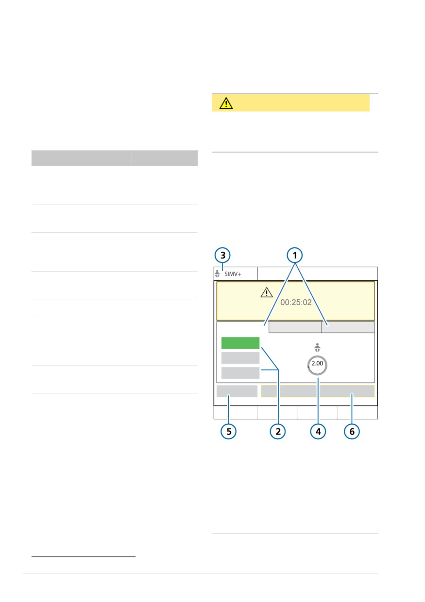
Figure 6-1. Neonatal Standby window
Select and assemble the
Section 6.1.2
appropriate breathing
circuit and components.
Adjust the position of the
Section 6.1.2.6
breathing circuit.
Connect external devices.
Chapter 4
Perform the preopera-
Sections 6.2 and
tional check and any
5.4
required tests and calibra-
tions.
Select the ventilation
Sections 6.3 and
mode.
5.5
1
Patient group
4
Weight
tabs (Neonatal
selected)
2
Quick setup
5
Preop check
buttons
3
Selected mode
6
Start ventilation42
and patient group
42 When HiFlowO2 is selected: Start therapy; when CPR ventilation is on: Start CPR.
116
English | 10103179/02 USA
Setting up the patient breathing circuit
6
To select the patient group
6.1.2.1 Selecting the breathing circuit
components
1. In the Standby window, touch the
Neonatal tab. See Figure 6-1.
Select the correct breathing circuit and
2. Touch the appropriate Quick setup
components for your patient from Table
button.
6-2.
By default, they are labeled Neonatal
Table 6-2. Neonatal breathing circuit part
1, Neonatal 2, and Neonatal 3. The
specifications
Quick setup names and settings are
defined in Configuration. For details,
Patient group/Compo-
Specification
see Section 5.2.1.
nent
3. Touch the Weight control and set the
Patient group
Neonatal
patient’s body weight.
Weight (kg)
0.2 to 30
By default, the weight is set to 2 kg.
Breathing circuit tube ID
10 to 12
You can now select the ventilation mode,
(mm)
if the desired mode is not already selected.
Flow sensor
Neonatal
6.1.2 Setting up the patient breathing
Pressure line
Neonatal
circuit
CO2 airway adapter
Neonatal
Setting up a neonatal breathing circuit
comprises the following steps:
6.1.2.2 Connecting the neonatal breath-
Table 6-1. Assembling the breathing circuit
ing circuit
Figures 2-9 through 2-11 in Chapter 2
To ...
See ...
show typical neonatal breathing circuit
Select the components
Section 6.1.2.1
configurations.
Connect the breathing
Section 6.1.2.2
circuit
6.1.2.3 Working with the expiratory valve
Connect the flow sensor
Section 6.1.2.4
The process is the same as for adult and
pediatric patients. See Section 3.5.2.
Connect the pressure line Section 6.1.2.5
(nCPAP, nCPAP-PC modes)
Position the circuit
Section 6.1.2.6
Hamilton Medical | HAMILTON-T1 Operator's Manual
117
6 Specifying neonatal settings
6.1.2.4 Connecting the neonatal flow
6.1.2.5 Connecting the pressure-monitor-
sensor
ing line
Note the following:
Use the pressure line with the breathing
circuit when using the nCPAP or nCPAP-PC
• Use a Hamilton Medical neonatal flow
modes. Do not use a flow sensor.
sensor to ventilate your neonatal
patient.
The pressure is measured by a built-in T-
• Do not use an adult/pediatric flow
piece adapter in the inspiratory line, close
sensor.
to the patient, or (if available) over the
optional pressure measuring connection at
• The neonatal flow sensor adds 1.3 ml
the Y-piece of the breathing circuit.
of dead space.
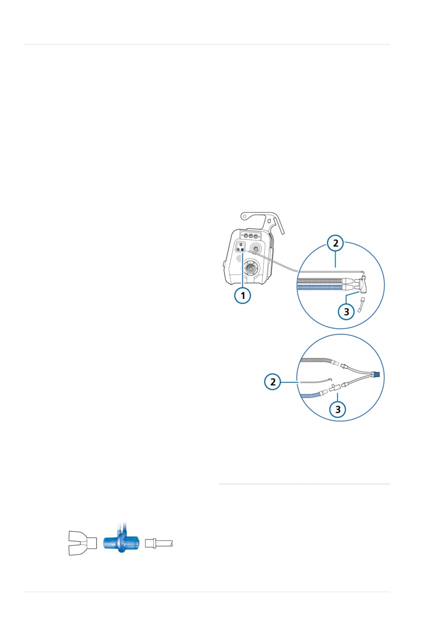
Figure 6-3. Connecting the pressure line
To connect the neonatal flow sensor
1.
For all modes except nCPAP and
nCPAP-PC, connect a flow sensor
between the Y-piece of the breathing
circuit and the patient connection. See
Figure 6-2.
When using the nCPAP and nCPAP-PC
modes, remove the flow sensor and
use the pressure-monitoring line with
the breathing circuit (Section 6.1.2.5).
Note that during calibration you place
the flow sensor proximal to the
patient.
HiFlowO2 does not require the use of
a flow sensor.
2.
Connect the blue and clear tubes to
the flow sensor connection ports on
the ventilator.
The blue tube attaches to the blue
1
Pressure line
3
T-piece, Y-piece
connection port. The clear tube
connection port
attaches to the white connection port.
(blue)
3.
Calibrate the flow sensor and perform
2
Pressure line
the Leak test. See Section 6.2.
Figure 6-2. Connect flow sensor between the
Y-piece and patient interface
118
English | 10103179/02 USA
Positioning the breathing circuit
6
To connect the pressure-monitoring line
To perform the preoperational check
1. Using an adapter, connect the pres-
1. Use a setup as described in Table 6-3.
sure line to the small inlet at the top
2. Perform all of the steps in Table 6-4.
of the T- or Y-piece, whichever is
used. See Figure 6-3.
To ensure that the ventilator functions
according to specifications on your
2. Connect the pressure line to the blue
patient, perform the preoperational check
flow sensor connection port on the
using the breathing circuit that will be
ventilator.
used on the patient.
3. Calibrate the breathing circuit and
perform the Leak test.
Table 6-3. Test breathing circuit setup
Component
Specification
6.1.2.6 Positioning the breathing circuit
Breathing
Neonatal, ID10 to ID12
After assembly, position the breathing cir-
circuit
cuit so that the hoses will not be pushed,
pulled, or kinked as a result of a patient's
Flow sensor
Neonatal, with calibration
movement, transport, or other activities,
adapter
including scanner bed operation and
Pressure line
For use in nCPAP and nCPAP-
nebulization.
PC modes
Test lung
Neonatal, with neonatal ET
6.2 Performing the preopera-
tube between flow sensor
tional check, tests, and calibra-
and lung model (an IngMar
tions
neonatal lung model is rec-
ommended)
Before proceeding, review the safety
information in Chapter 1.
Table 6-4. Preoperational check, overview
The following sections in this chapter pro-
vide information that is specific to neona-
To ...
See ...
tal ventilation, and is intended as a supple-
Perform the preoperational
Section 5.4 in
ment to the information provided in
check
Chapter 5
Chapter 5.
Perform the Leak test
Section 5.4.2
For details about when to perform the
in Chapter 5
tests, and about the full preoperational
check process, see Section 5.4.
Calibrate the neonatal flow Section 6.2.1
sensor
When to perform
In nCPAP modes, calibrate
Section 6.2.2
Before connecting a new patient to the
the breathing circuit
ventilator.
Perform other calibrations,
Section 5.4 in
as needed
Chapter 5
Hamilton Medical | HAMILTON-T1 Operator's Manual
119
6 Specifying neonatal settings
6.2.1 Calibrating the neonatal flow
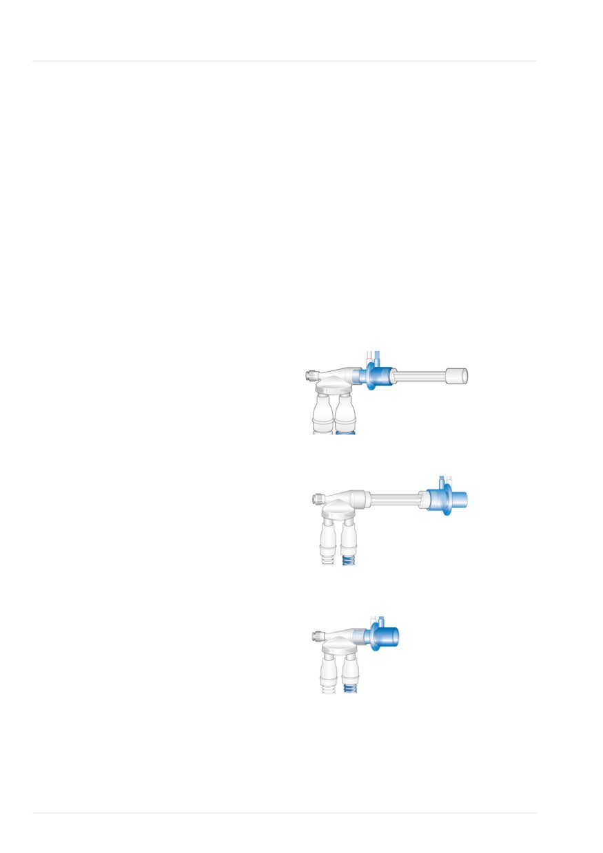
7. When prompted, flip the flow sensor
sensor
and calibration adapter together 180°
so the adapter is directly connected to
Calibrate the flow sensor after connecting
the Y-piece (Figure 6-5).
a new flow sensor or whenever the Flow
8. When prompted, flip the flow sensor/
sensor calibration needed alarm is genera-
adapter 180° again, so the flow
ted.
sensor is directly connected to the Y-
A flow sensor is required for all modes
piece, and remove the calibration
except nCPAP or nCPAP-PC modes or when
adapter (Figure 6-6).
using HiFlowO2. Before proceeding,
9. When calibration is complete, verify
ensure you have the calibration adapter
that there is a checkmark in the Flow
available.
sensor checkbox.
To calibrate a neonatal/pediatric flow
10. When successful, continue with other
sensor
tests or ventilation.
1. Calibrate the flow sensor in Standby,
Figure 6-4. Attach adapter
with no patient connected.
2. Make sure that the Neonatal patient
group is selected, a neonatal flow
sensor is connected, and the calibra-
tion adapter is available.
3. Set up the ventilator for ventilation,
connecting the flow sensor to the Y-
Figure 6-5. Flip components
piece.
4. In the Standby window, touch Preop
check.
The System > Tests & calib window is
displayed.
5. Touch Flow sensor.
6. When prompted on the display, attach
Figure 6-6. Flip components, remove adapter
the calibration adapter to the patient
end of the flow sensor (Figure 6-4).
To cancel an ongoing calibration
4 Touch Flow sensor again.
120
English | 10103179/02 USA
Calibrating the neonatal breathing circuit (nCPAP and nCPAP-PC modes)
6
In case of calibration failure
To calibrate the circuit with the pressure
line
If the calibration fails, a red X is displayed
1. Touch System > Tests & calib.
in the Flow sensor checkbox.
2. Touch Circuit.
Perform the following checks, repeating
the calibration after each one, until calib-
If you have not already disconnected
ration is successful:
the patient, the text Disconnect patient
is displayed.
• Ensure that the flow sensor is appropri-
3. Disconnect patient as follows:
ate for the selected patient group.
- If using a Y-piece, disconnect the
• Check the breathing circuit for a dis-
breathing circuit from the patient.
connection between the ventilator and
the flow sensor, or for other large leaks
- If using a T-piece, disconnect the
interface from the patient.
(for example, breathing circuit, humidi-
fier).
4. Follow the instructions displayed in
the message line.
• Check that the correct flow sensor is
connected, and that the flow sensor
5. When calibration is complete, verify
and expiratory valve/membrane are
that there is a checkmark in the Circuit
properly seated.
checkbox.
• If the calibration still fails, replace the
6. When successful, continue with other
flow sensor.
tests or ventilation.
• If the calibration still fails, replace the
To cancel an ongoing calibration
expiratory valve membrane.
4 Touch Circuit again.
• If the calibration still fails, replace the
expiratory valve set.
If the problem persists, have the ventilator
serviced.
6.2.2 Calibrating the neonatal breath-
ing circuit (nCPAP and nCPAP-PC
modes)
The nCPAP and nCPAP-PC modes use a
pressure line in the breathing circuit to
measure the inspiratory pressure. Do not
use a flow sensor.
This calibration ensures that the breathing
circuit resistance compensation is accu-
rate.
Hamilton Medical | HAMILTON-T1 Operator's Manual
121
6 Specifying neonatal settings
In case of calibration failure
6.4 Setting the patient weight
If the calibration fails, a red X is displayed
for ventilation
in the Circuit checkbox.
For neonates, the ventilator uses actual
Perform the following checks, repeating
body weight (instead of a calculated IBW),
the calibration after each one, until calib-
set in the Weight control.
ration is successful:
Specifying the correct weight is particu-
• Check the breathing circuit for a dis-
larly important as the ventilator uses this
connection between the ventilator and
data as the basis for some calculations and
the pressure line, or for other large
mode control settings. By default, neona-
leaks (for example, breathing circuit,
tal weight is set to 2 kg.
humidifier).
To set up the patient, see Section 6.1.1.
• Check that the pressure line and expira-
tory valve set is properly seated.
6.5 Alarms for neonatal ventila-
• If the calibration fails, replace the pres-
sure line.
tion
• If the calibration still fails, replace the
Note that the following adjustable alarms
breathing circuit and expiratory valve
use patient Weight to set the initial alarm
set.
limits:
If the problem persists, have the ventilator
• Tidal volume, high and low (Vt)
serviced.
• Minute volume, high and low
(ExpMinVol)
6.3 Selecting the ventilation
Be sure to set the correct patient Weight in
mode
the Standby window before starting venti-
lation. See Section 6.1.1.
The neonatal modes available on the
ventilator are either pressure controlled or
adaptive (pressure regulated and volume
6.6 O2 enrichment for
targeted).
neonates
Note that the ventilator generates a con-
The applied oxygen concentration during
tinuous and constant base flow from the
the enrichment maneuver is increased to
inspiratory outlet to the expiratory outlet
125% of the current Oxygen setting.
during the later part of exhalation.
For additional details on performing O2
The base flow is set to a fixed 4 l/min for
enrichment, see Chapter 10.
neonatal patients.
For the list of supported modes and details
about each one, see Chapter 7.
To select the ventilation mode
4 See Section 5.5.
122
English | 10103179/02 USA
7
Ventilation modes
7.1
Overview
124
7.2
Volume-targeted modes, adaptive pressure control
128
7.3
Pressure-controlled modes
132
7.4
Intelligent Ventilation
138
7.5
Noninvasive modes
140
7.6
Special conditions
146
7.7
Working with noninvasive modes
148
7.8
Working with ASV
152
123
7 Ventilation modes
7.1 Overview
To select the breath timing to use, see
Section 13.4.1.
The HAMILTON-T1 offers a full range of
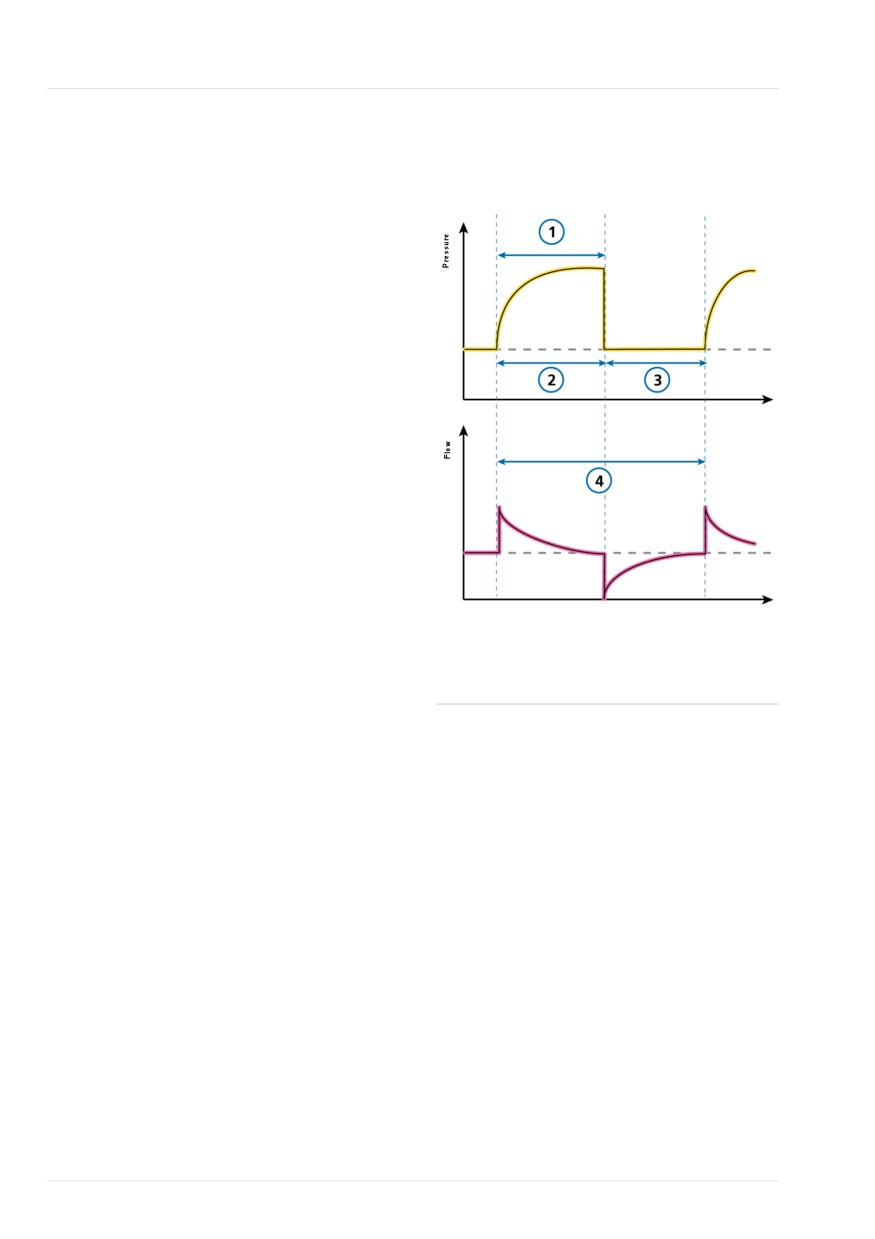
Figure 7-1. Breath timing parameters
ventilation modes that provide full and
partial ventilatory support.
The primary aims of mechanical ventilation
are:
• Elimination of CO2
• Oxygenation
• Decreased work of breathing
• Patient synchronization
Time
The detailed mode descriptions provided
in this chapter illustrate how the controls
work to achieve these goals.
For a comparison of Hamilton Medical
ventilation-related terminology with ISO
19223:2019, see Section 15.5.
Time
7.1.1 Breath types and timing options
1
TI
4
Rate
Hamilton Medical ventilators support two
2, 3
I:E ratio
main breathing methods: mandatory
breaths and spontaneous breaths.
Note that in the breath patterns shown in
Mandatory breaths. The start of inspiration
this chapter, we show I:E. What is actually
(triggering) is determined by the ventilator
displayed on your device depends on the
or the patient. The end of inspiration
breath timing selection on the ventilator.
(cycling) is determined by the ventilator.
Spontaneous breaths. The start of inspira-
tion (triggering) and end of inspiration
(cycling) is determined by the patient. The
patient breathes independently or receives
support from the ventilator.
The ventilator controls mandatory breath
timing using a combination of inspiratory
time (TI) and Rate.
For some modes, you can set the ventila-
tor to use any of the following combina-
tions to control breath timing: I:E or TI.
124
English | 10103179/02 USA

Ventilation modes
7
7.1.2 Ventilation modes
A ventilation mode combines breath type,
breath sequence, and control variables.
The choice of mode is a medical decision
that depends on the patient’s CO2 elimi-
The following tables provide an overview
nation, oxygenation, activity, and breath-
of the available ventilation modes.
ing effort.
Table 7-1. HAMILTON-T1 ventilation modes, description and applicable patient group
Mode name
Patient
Mode
group
Volume-targeted modes, adaptive pressure controlled
APVcmv /
All
Breaths are volume targeted and mandatory.
(S)CMV+
APVsimv /
All
Volume-targeted mandatory breaths can be alternated with
SIMV+
pressure-supported spontaneous breaths.
Pressure-controlled modes
PCV+
All
All breaths, whether triggered by the patient or the ventilator,
are pressure-controlled and mandatory.
PSIMV+
All
Mandatory breaths are pressure controlled. Mandatory breaths
can be alternated with pressure-supported spontaneous
breaths.
DuoPAP
All
Mandatory breaths are pressure controlled. Spontaneous
breaths can be triggered at both pressure levels.
APRV
All
Spontaneous breaths can be continuously triggered. The pres-
sure release between the levels contributes to ventilation.
SPONT
All
Every breath is spontaneous, with or without pressure-sup-
ported spontaneous breaths.
Intelligent ventilation
ASV
Adult/Ped
Operator sets %MinVol, PEEP, and Oxygen. Frequency, tidal
volume, pressure, and I:E ratio are based on physiological input
from the patient.
Hamilton Medical | HAMILTON-T1 Operator's Manual
125
7 Ventilation modes
Mode name
Patient
Mode
group
Noninvasive modes
NIV
All
Every breath is spontaneous.
NIV-ST
All
Every breath is spontaneous as long as the patient is breathing
above the set rate. A backup rate can be set for mandatory
breaths.
nCPAP
Neonatal
Demand flow Nasal Continuous Positive Airway Pressure.
nCPAP-PC
Neonatal
Breaths are pressure controlled and mandatory.
126
English | 10103179/02 USA

Mode type
Intelligent
Vol targeted, adaptive
Pressure controlled
Noninvasive
Ventilation
press. control
Mode
ASV
APVcmv
APVsimv
PCV+
PSIMV
PSIMV+
DuoPAP
APRV
SPONT
NIV
NIV-ST
nCPAP**
nCPAP-PC
***
+PSync
**
Timing
Rate
Rate
Rate
Rate
Rate
Rate
T low
Rate
--
Rate
TI
TI
TI
T high
T high
TI
--
TI
Mandatory
Vt
Vt
ΔPcontrol
ΔPinsp
ΔPcontrol
P high
P high
ΔPinsp
--
ΔPcontrol
breaths
Spontaneous
ΔPsupport
--
ΔPinsp
ΔPsupport
ΔPsupport
ΔPsupport
ΔPsupport
ΔPinsp
--
--
breaths
ETS
ETS
ETS
ETS
ETS
ETS
ETS
ETS
--
--
TI max
TI max
--
--
Baseline press.
PEEP/CPAP
P low
Trigger
P-ramp
Plimit
Oxygen
Sex
Pat. height
Mode specific
%MinVol
Sigh***
Apnea
backup
APVsimv
APVsimv
APVsimv
APVsimv
PCV+
* I:E, TI
** Neonatal only
*** Adult/Ped only-
- N/A
X applies to this mode
7 Ventilation modes
7.2 Volume-targeted modes,
adaptive pressure control
The following modes are volume targeted,
with adaptive pressure control:
• APVcmv / (S)CMV+
• APVsimv / SIMV+
• VS
In this manual, we refer to the APV modes
using the APVcmv / APVsimv nomencla-
ture. You can select the format to use in
Configuration (Section 13.4.2).
NOTICE
•
The minimum inspiratory pressure
(Ppeak - PEEP) in APVcmv and
APVsimv modes is 5 cmH2O. Be aware
that a small set tidal volume with high
lung compliance may lead to higher-
than-expected tidal volumes.
•
Ensure Plimit is set appropriately for
adaptive modes. This setting provides
a safety pressure limit for the device
to appropriately adjust the inspiratory
pressure necessary to achieve the
target tidal volume.
The maximum available inspiratory
pressure (Plimit), is indicated by a blue
line on the pressure waveform
display.
If Plimit is set too low, there may not
be enough margin for the device to
adjust its inspiratory pressure to
deliver the target tidal volume.
128
English | 10103179/02 USA
APVcmv / (S)CMV+ mode
7
7.2.1 APVcmv / (S)CMV+ mode
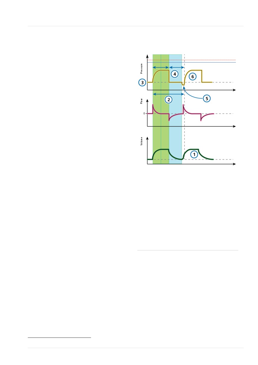
Figure 7-2. APVcmv / (S)CMV+: Breathing pat-
tern and controls
APVcmv stands for adaptive pressure venti-
Insp
Exp
lation with controlled mandatory ventila-
tion. This mode is also called (S)CMV+,
which stands for synchronized controlled
mandatory ventilation.
APVcmv is a volume-targeted pressure-
controlled ventilation mode. It functions
Time
similarly to the conventional volume-
controlled mode of ventilation, (S)CMV,
except that pressure is the control variable
rather than flow. Pressure is adjusted
between breaths to achieve the target
Time
tidal volume.
The breath can be triggered by the ventila-
tor or by the patient. If the breath is trig-
gered by the patient, the inspiratory rate
may increase.
Time
The ventilator uses the Plimit setting (high
Ventilator controls
Pressure alarm limit minus 10 cmH2O) as a
CO2 elimination
safety boundary for its inspiratory pressure
adjustment, and does not exceed this
1
Vt
2
Rate
value. An exception is Sigh breaths, when
Sigh (not shown)
the ventilator may apply inspiratory pres-
Oxygenation
sures 3 cmH2O below the high Pressure
3
PEEP
4
I:E43
alarm limit.
Oxygen (not shown)
Breaths in APVcmv mode are volume-tar-
Patient synchronization
geted and mandatory, delivered at the
5
Trigger
6
P-ramp
lowest possible pressure depending on
lung conditions.
The operator sets the target tidal volume
(Vt).
The ventilator delivers the set target
volume (Vt) at a preset rate. The patient
can trigger mandatory breaths between
preset rate breaths.
43 Depending on the selected breath timing philosophy.
Hamilton Medical | HAMILTON-T1 Operator's Manual
129
7 Ventilation modes
7.2.2 APVsimv / SIMV+ mode
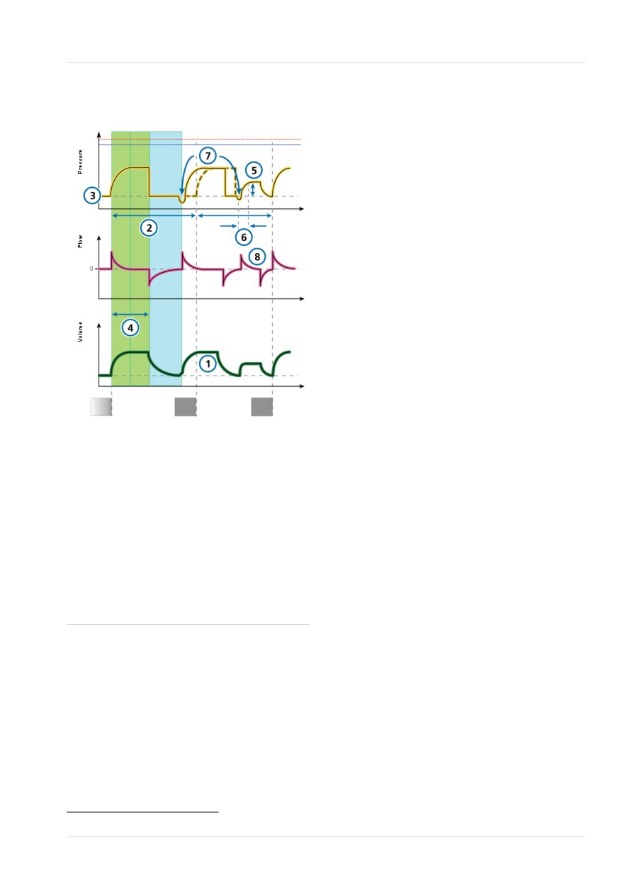
If the patient does not trigger a breath
during Tspont, the ventilator automatically
APVsimv stands for adaptive pressure
delivers a mandatory breath at the end of
ventilation with synchronized intermittent
Tmand.
mandatory ventilation. This mode is also
called SIMV+, synchronized intermittent
In this mode, parameters for both manda-
mandatory ventilation plus.
tory and spontaneous breath types are set.
•
The tidal volume (Vt) setting defines the
The APVsimv mode combines attributes of
delivered volume of mandatory breaths.
the APVcmv and SPONT modes, delivering
volume-targeted mandatory breaths or
•
Rate and I:E define the timing of the
pressure-supported spontaneous (patient-
breath cycle for mandatory breaths.
triggered) breaths.
•
For spontaneous breaths, ΔPsupport
APVsimv mode ensures that the set target
defines the pressure support above
volume is delivered during the mandatory
PEEP.
breaths.
•
ETS affects the inspiratory timing of the
After the mandatory breath is delivered,
supported breaths.
the patient is free to take any number of
The inspiratory time can also be limited
spontaneous breaths for the remainder of
by TI max.44
the APV breath interval.
The ventilator uses the Plimit setting (high
Pressure alarm limit minus 10 cmH2O) as a
safety boundary for its inspiratory pressure
adjustment, and does not exceed this
value. An exception is Sigh breaths, when
the ventilator may apply inspiratory pres-
sures 3 cmH2O below the high Pressure
alarm limit.
Each breath interval includes mandatory
time (Tmand) and spontaneous time
(Tspont).
• If the patient triggers a breath during
Tmand, the ventilator immediately
delivers a mandatory breath.
• If the patient triggers a breath during
Tspont, the ventilator delivers a sponta-
neous pressure-supported breath.
44 TI max is only available for adult/pediatric patients if it is enabled in Configuration (Section 13.4.4). It is always available for
neonates.
130
English | 10103179/02 USA
APVsimv / SIMV+ mode
7
Figure 7-3. APVsimv / SIMV+: Breathing pattern
and controls
Insp
Exp
Time
Time
Time
Tmand
Tspont
Tmand
Tspont
Tmand
Ventilator controls
CO2 elimination
1
Vt
2
Rate
Sigh (not shown)
Oxygenation
3
PEEP
5
ΔPsupport
4
I:E45
Oxygen (not shown)
Patient synchronization
6
P-ramp
8
ETS
7
Trigger
45 Depending on the selected breath timing philosophy.
Hamilton Medical | HAMILTON-T1 Operator's Manual
131