HAMILTON-T1. Operator's Manual (2022) - page 1
Operator's Manual
HAMILTON-T1
2022-12-15
10103179/02 USA
cal AG parts were used when replacing
reserved.
parts, or if serial numbers were amended,
deleted, or removed.
No part of this publication may be repro-
duced, stored in a database or retrieval
If returning parts to Hamilton Medical AG,
system, or transmitted in any form or by
be sure to use the standard Hamilton
any means, electronic, mechanical, or by
Medical returned goods authorization
photocopying, recording, or otherwise,
(RGA) procedure. Disposal of parts shall
without prior written permission of Hamil-
follow all local, state, and federal regula-
ton Medical AG.
tion with respect to environmental protec-
tion.
This document may be revised, replaced,
or made obsolete by other documents by
For all proprietary and third-party trade-
Hamilton Medical AG at any time and
marks used by Hamilton Medical AG, see
without notice. Ensure that you have the
www.hamilton-medical.com/trademarks.
most current applicable version of this
document; if in doubt, contact the techni-
For devices manufactured in Switzerland
cal support department of Hamilton
Manufacturer:
Medical AG, Switzerland. While the
Hamilton Medical AG
information set forth herein is believed to
Via Crusch 8, CH-7402 Bonaduz
be accurate, it is not a substitute for the
Switzerland
exercise of professional judgment.
Phone: (+41) 58 610 10 20
info@hamilton-medical.com
Nothing in this document shall limit or
restrict in any way Hamilton Medical AG’s
right to revise or otherwise change or
modify the equipment (including its soft-
Distributor in USA
ware) described herein, without notice. In
Hamilton Medical, Inc.
the absence of an express, written agree-
4655 Aircenter Circle
ment to the contrary, Hamilton Medical
Reno, NV 89502
AG has no obligation to furnish any such
Phone: (775) 858-3200
revisions, changes, or modifications to the
Toll-free: (800) 426-6331
owner or user of the equipment (includ-
info@hamiltonmedical.com
ing software) described herein.
The equipment must be operated, ser-
For devices manufactured and sold in the USA
viced, or upgraded only by trained profes-
Printed in the USA.
sionals. Hamilton Medical AG’s sole
responsibility with respect to the equip-
Manufactured for:
ment and its use is as stated in the limited
Hamilton Medical AG
warranty provided in the device Opera-
Via Crusch 8, CH-7402 Bonaduz
tor’s Manual.
Switzerland
Phone: (+41) 58 610 10 20
Hamilton Medical AG shall not be liable
info@hamilton-medical.com
for any loss, cost, expense, inconvenience,
or damage that may arise out of misuse
of the product, or if non-Hamilton Medi-
4
English | 10103179/02 USA
Table of Contents
Preface
17
Chapter 1
Safety information
21
1.1
Overview
22
1.2
Intended use
22
1.3
Electromagnetic susceptibility
22
1.4
Fire and other hazards
23
1.5
General operation and setup
24
1.5.1
General operation and setup
24
1.5.2
Electrical: power and batteries
25
1.5.3
Gas supply
26
1.5.4
USB ports
27
1.5.5
Transport
27
1.6
Setting up for ventilation
28
1.6.1
Patient breathing circuits, components, and accessories
28
1.6.2
Preoperational check and tests
29
1.6.3
Humidifier
29
1.6.4
CO2 sensor setup and operation
29
1.6.5
Nebulization
31
1.6.6
Speaking valve
32
1.7
Ventilating the patient
32
1.7.1
Specifying patient settings
32
1.7.2
Neonatal ventilation
33
1.7.3
Apnea backup
33
1.7.4
Noninvasive ventilation
34
1.8
Monitoring and alarms
34
1.9
Using the trolley
35
1.10
Maintenance
35
1.10.1
General maintenance, cleaning, and disinfection
35
1.10.2
Preventive maintenance
36
Hamilton Medical | HAMILTON-T1 Operator's Manual
5
Table of Contents
1.10.3
O2 sensor
37
1.11
Service and testing
37
Chapter 2
System overview
39
2.1
Overview
40
2.1.1
Standard features and options
40
2.2
Physical descriptions
43
2.2.1
About the ventilator
44
2.2.2
About the main display
48
2.2.3
About the patient breathing circuits
49
2.2.4
About the trolley and mounting variations
54
2.3
Turning the ventilator on and off
54
2.4
Navigating the windows and controls
55
2.4.1
Accessing windows
55
2.4.2
Adjusting controls
55
2.4.3
Selecting list items
56
2.4.4
Using shortcuts
56
Chapter 3
Preparing the ventilator
59
3.1
Overview
60
3.2
Connecting to a power source
60
3.2.1
Connecting to DC power
60
3.2.2
Working with the potential equalization conductor
61
3.2.3
Using battery power
61
3.3
Connecting the oxygen supply
63
3.3.1
Using a low-pressure oxygen supply
63
3.3.2
Connecting the oxygen supply to the ventilator
63
3.3.3
Selecting the oxygen source type
63
3.4
Ensuring an adequate oxygen supply for patient transport
64
3.4.1
Reviewing current oxygen consumption
64
3.4.2
Calculating estimated oxygen consumption
65
6
English | 10103179/02 USA
Table of Contents
3.5
Setting up the patient breathing circuit
70
3.5.1
Breathing circuit connections on the ventilator
70
3.5.2
Working with the expiratory valve set
71
3.5.3
Selecting the breathing circuit components
72
3.5.4
Assembling the patient breathing circuit
73
3.5.5
Positioning the breathing circuit
74
3.5.6
Changing breathing circuit components during ventilation
74
Chapter 4
Setting up external devices and sensors
75
4.1
Overview
76
4.2
Setting up a humidifier
76
4.3
Setting up CO2 monitoring
77
4.3.1
Mainstream CO2 measurement
77
4.3.2
Sidestream CO2 measurement
79
4.4
Setting up SpO2 monitoring
81
4.5
Enabling sensors
81
4.6
Setting up nebulization
82
4.7
Setting up a speaking valve
83
4.7.1
Activating speaking valve compatibility
83
4.7.2
Connecting a speaking valve to the breathing circuit set
84
4.7.3
Deactivating speaking valve compatibility
84
4.8
Connecting to external devices
85
Chapter 5
Specifying ventilation settings
87
5.1
Process overview
88
5.2
Selecting the patient group
88
5.2.1
About Quick setups: preconfigured settings
89
5.3
Entering patient data
90
5.4
Performing the preoperational check, tests, and calibrations
90
5.4.1
Performing the preoperational check
91
5.4.2
Performing the breathing circuit Leak test
92
Hamilton Medical | HAMILTON-T1 Operator's Manual
7
Table of Contents
5.4.3
Calibrating the adult/pediatric flow sensor
93
5.4.4
Calibrating the O2 sensor
95
5.4.5
Performing a zero calibration of the CO2 sensor/adapter
96
5.4.6
Testing the alarms
97
5.5
Selecting the ventilation mode
98
5.6
Reviewing and adjusting ventilation settings
99
5.6.1
About Plimit and related pressure-control settings
100
5.6.2
About Apnea backup ventilation
102
5.7
Setting alarm limits
103
5.7.1
About the Oxygen alarm limits
107
5.8
Starting ventilation
108
5.9
Stopping ventilation (Standby)
108
5.10
About the control parameters
109
Chapter 6
Specifying neonatal settings
115
6.1
Setting up for neonatal ventilation
116
6.1.1
Setting the patient group and weight
116
6.1.2
Setting up the patient breathing circuit
117
6.2
Performing the preoperational check, tests, and calibrations
119
6.2.1
Calibrating the neonatal flow sensor
120
6.2.2
Calibrating the neonatal breathing circuit (nCPAP and nCPAP-121
PC modes)
6.3
Selecting the ventilation mode
122
6.4
Setting the patient weight for ventilation
122
6.5
Alarms for neonatal ventilation
122
6.6
O2 enrichment for neonates
122
Chapter 7
Ventilation modes
123
7.1
Overview
124
7.1.1
Breath types and timing options
124
7.1.2
Ventilation modes
125
8
English | 10103179/02 USA
Table of Contents
7.2
Volume-targeted modes, adaptive pressure control
128
7.2.1
APVcmv / (S)CMV+ mode
129
7.2.2
APVsimv / SIMV+ mode
130
7.3
Pressure-controlled modes
132
7.3.1
PCV+ mode
132
7.3.2
PSIMV+ mode
133
7.3.3
PSIMV+ mode with PSync
134
7.3.4
DuoPAP mode
135
7.3.5
APRV mode
136
7.3.6
SPONT mode
137
7.4
Intelligent Ventilation
138
7.4.1
ASV mode
138
7.5
Noninvasive modes
140
7.5.1
NIV mode
141
7.5.2
NIV-ST mode
142
7.5.3
The nCPAP modes
143
7.6
Special conditions
146
7.6.1
Sensor Failure mode
146
7.6.2
Safety ventilation/Safety mode
146
7.6.3
Ambient state
148
7.7
Working with noninvasive modes
148
7.7.1
Required conditions for use
148
7.7.2
Contraindications
149
7.7.3
Potential adverse reactions
150
7.7.4
Control settings in noninvasive ventilation
150
7.7.5
Alarms in noninvasive ventilation
150
7.7.6
Monitored parameters in noninvasive ventilation
151
7.7.7
Additional notes about using noninvasive ventilation
151
Hamilton Medical | HAMILTON-T1 Operator's Manual
9
Table of Contents
7.8
Working with ASV
152
7.8.1
Contraindications
152
7.8.2
Setting up ASV on the ventilator
152
7.8.3
Clinical workflow with ASV
153
7.8.4
Maintaining adequate ventilation
154
7.8.5
Reviewing alarm settings
154
7.8.6
Monitoring ASV
155
7.8.7
Weaning
156
7.8.8
Functional overview
157
Chapter 8
Monitoring ventilation
161
8.1
Overview
162
8.2
Viewing numeric patient data
162
8.2.1
About the main monitoring parameters (MMP)
162
8.2.2
Viewing patient data in the Monitoring window
163
8.3
Viewing graphical patient data
163
8.3.1
Selecting display options
164
8.3.2
Working with waveforms
165
8.3.3
Working with Trend graphs
167
8.3.4
Working with loops
168
8.4
Working with Intelligent panels
169
8.4.1
Dynamic Lung panel: real-time ventilation status
169
8.4.2
Vent Status panel: real-time ventilator dependence status
172
8.4.3
ASV Graph panel: real-time patient condition and targets
173
8.5
About the monitored parameters
174
8.6
Viewing patient ventilation time
183
8.7
Viewing device-specific information
183
10
English | 10103179/02 USA
Table of Contents
Chapter 9
Responding to alarms
185
9.1
Overview
186
9.1.1
Alarm limit indicators
189
9.1.2
Responding to an alarm
189
9.1.3
Temporarily silencing an alarm
190
9.2
About the alarm buffer
190
9.2.1
Accessing on-screen troubleshooting help
192
9.3
Adjusting alarm loudness (volume)
192
9.4
Troubleshooting alarms
193
Chapter 10
Ventilation settings and functions
213
10.1
Overview
214
10.2
Accessing settings during ventilation
214
10.2.1
Accessing patient data during ventilation
214
10.2.2
Accessing settings during ventilation
215
10.3
Entering/exiting Standby
216
10.4
Oxygen enrichment
217
10.4.1
Performing an open-suctioning maneuver
217
10.4.2
About closed-suctioning maneuvers
218
10.5
High flow oxygen therapy
219
10.5.1
Working with high flow oxygen therapy
219
10.6
Manual breath
220
10.7
Working with a nebulizer
220
10.7.1
Working with a pneumatic nebulizer
220
10.8
Working with a speaking valve
221
10.8.1
Mode changes that automatically turn off compatibility
221
10.8.2
Speaking valve-related control settings
221
10.8.3
Parameters monitored when compatibility is activated
222
10.8.4
Speaking valve-related alarms
222
Hamilton Medical | HAMILTON-T1 Operator's Manual
11
Table of Contents
10.9
CPR ventilation
223
10.9.1
About the CPR modes and settings
224
10.9.2
Working with CPR ventilation
224
10.9.3
Monitoring and display during CPR
225
10.9.4
CPR-related alarms
225
10.10
Locking and unlocking the touch screen
226
10.11
Capturing a screenshot
226
10.12
Setting display options
227
10.12.1
Setting date and time
227
10.12.2
Day and night display brightness
227
10.13
About the Event log
228
10.13.1
Copying event log data
229
Chapter 11
Working with external devices
231
11.1
Working with the HAMILTON-H900 humidifier
232
11.1.1
Accessing humidifier controls on the ventilator
232
11.1.2
About the humidification modes
234
11.1.3
Changing humidity using temperature controls
236
11.1.4
Entering Standby
237
11.1.5
Turning the humidifier on/off
237
11.1.6
About humidifier-related alarms
237
11.1.7
About humidifier-related parameters
241
11.2
Working with smartphones and clinical networks
242
11.2.1
Setting up a Hamilton Connect App account
242
11.2.2
Enabling a connection type
242
11.2.3
Setting up a Bluetooth connection
244
11.2.4
Setting up a Wi-Fi Access Point
244
11.2.5
Setting up a Wireless LAN (Wi-Fi) connection
245
11.2.6
Connecting to a network using Ethernet
246
11.2.7
Disconnecting a paired smartphone
246
12
English | 10103179/02 USA
Table of Contents
Chapter 12
Maintenance
247
12.1
Overview
248
12.2
Cleaning, disinfection, and sterilization
248
12.3
Preventive maintenance
252
12.4
Performing maintenance tasks
253
12.4.1
Maintaining the filters
253
12.4.2
Replacing the galvanic O2 sensor
254
12.4.3
Charging and storing batteries
254
12.4.4
Replacing batteries
254
12.5
Repacking and shipping
255
Chapter 13
Configuration
257
13.1
Overview
258
13.2
Accessing Configuration mode
258
13.3
Configuring general settings
258
13.3.1
Selecting the default language
258
13.3.2
Selecting the units of measure
258
13.3.3
Enabling the communication interface
258
13.3.4
Setting the minimum alarm loudness (volume)
259
13.3.5
Setting sensitivity for Check flow sensor for water alarm
259
13.3.6
Setting the maximum available Flow in HiFlowO2 for
259
neonates
13.4
Selecting mode options
259
13.4.1
Setting breath timing options
260
13.4.2
Choosing the mode naming convention
260
13.4.3
Choosing the ASV version
260
13.4.4
Enabling TI max for invasive modes
260
13.5
Configuring MMPs
260
13.6
Defining Quick setups
261
13.6.1
Configuring individual setup settings
261
13.6.2
Selecting a default Quick setup
262
Hamilton Medical | HAMILTON-T1 Operator's Manual
13
Table of Contents
13.7
Activating SpO2 and CO2 measurement
262
13.8
Configuring CPR ventilation
262
13.9
Configuring connectivity settings
262
13.9.1
Updating Hamilton Connect Module firmware
263
13.9.2
Copying Connectivity configuration settings
263
13.9.3
Setting the Hamilton Connect Module to the factory default
264
settings
13.9.4
Removing device pairings
264
13.9.5
Deleting data from the Hamilton Connect Module
265
13.10
Copying configuration settings
265
13.11
Configuring device options
266
13.11.1
Reviewing installed options
266
13.11.2
Adding software options
266
13.11.3
Activating hardware options
266
13.11.4
Removing options
267
Chapter 14
Parts and accessories
269
14.1
Overview
270
Chapter 15
Specifications
279
15.1
Physical characteristics
280
15.2
Environmental requirements
281
15.3
Pneumatic specifications
283
15.4
Electrical specifications
284
15.5
Ventilation-related terminology
286
15.6
Control settings
289
15.7
Monitored parameters
294
15.8
Alarms
300
15.9
Configuration
303
15.10
ASV technical data
306
15.11
Ventilator breathing system specifications
308
14
English | 10103179/02 USA
Table of Contents
15.12
Technical performance data
309
15.12.1
Accuracy testing
315
15.12.2
Essential performance
315
15.12.3
Estimated oxygen consumption relative to minute volume
316
15.13
Functional description of ventilator system
317
15.13.1
Gas supply and delivery
317
15.13.2
Gas monitoring with the flow sensor
318
15.13.3
Pneumatic diagram
319
15.14
Symbols used on device labels and packaging
320
15.15
Standards and approvals
322
15.16
Disposal and year of manufacture
324
15.17
Warranty
325
Glossary
327
Index
335
Hamilton Medical | HAMILTON-T1 Operator's Manual
15
Preface
HAMILTON-T1 Documentation
Table 1. HAMILTON-T1 documentation suite
Document title
Description
Operator’s Manual (this guide)
Provides detailed information about the setup and use
of the HAMILTON-T1 ventilator.
Pulse Oximetry Instructions for Use
Provides setup and use information for using SpO2 and
related sensors with the ventilator.1
Volumetric Capnography User Guide
Provides reference information for CO2 capnography.1
HAMILTON-H900 Instructions for Use
Provides specifications and setup and use information
for the HAMILTON-H900 humidifier.1
Hamilton Connect App Instructions for
Provides detailed information about the setup and use
Use
of the Hamilton Connect App.
Communication Interface User Guide
Provides an overview of the communication interface,
including how to connect the ventilator to external
devices for data communication and support for nurse
call remote alarms.
Service Manual
Provides information about installing and setting up the
medical equipment, as well as additional technical and
servicing information for the ventilator.
Communication Board User Guide
Provides information about installing and configuring
communication boards.
Hamilton Connect Communication
Provides reference information for network connectivity
and Configuration Guide
and information about enabling connection types on
your device.
EMC Declarations Guide
Provides emissions and EMC-related safety and use
information.
Be sure to read the documentation before
using the device or accessories.
1 If option is installed.
Hamilton Medical | HAMILTON-T1 Operator's Manual
17

Preface
To download the latest version of this
•
A green check mark or button
manual or other documents, visit the
Resource Center website:
indicates a selected item or
feature.
Resource-center.html
•
The graphics shown in this manual may
not exactly match what you see in your
A QR code on the ventilator provides a
environment.
link to the Resource Center website, where
you can download this manual and rela-
•
The term USB drive refers to a passive
ted product documentation. See Section
USB memory device, also known as a
8.7.
USB flash drive or USB memory stick.
Training
•
Some figures use callouts in a white
circle with a blue border.
Hamilton Medical offers the Hamilton
These figures may have an associ-
Medical College, which provides a variety
ated legend table, or may provide the
of learning modules free of charge. To
legend in the figures title, if a single
register, go to: http://college.hamilton-
item. Callouts may be numeric or
medical.com
alphabetic. Callouts are unrelated to
Conventions used in this guide
any nearby procedures and refer only
to the figures themselves and their
In this manual:
associated legend.
•
Button and tab names are shown in a
•
Some figures use small dark blue call-
bold font.
outs.
•
The notation XX > XX shows the
These callouts show the sequence
sequence of buttons/tabs to touch to
of steps. They are not directly related
open the associated window.
to the numbering in the text of any
For example, the text "Touch System >
associated procedure.
Settings" means touch the System
•
Not all features or products are avail-
button, then touch the Settings tab.
able in all markets.
•
Window names are shown using the
•
Product description and order number
sequence of buttons/tabs used to open
may differ depending on region.
them.
For example, "Alarms > Limits 2
•
Units of measure: Pressure is indicated
window" means the window is
in cmH2O, length in cm, and tempera-
accessed by touching the Alarms
ture in degrees Celsius (°C). The units
button, then the Limits 2 tab.
of measure for pressure and length are
configurable.
•
Software version: The software version
for the ventilator is displayed in the
System > Info window and should
match the version on the title page of
this manual.
18
English | 10103179/02 USA
Preface
• All patient-related pressure, volume,
and flow measurements are expressed
NOTICE!
in BTPS (body temperature and pres-
sure saturated).
• Pneumatic-related pressure, volume,
CAUTION
and flow measurements are expressed
Federal law restricts this device to sale by
in STPD (standard temperature and
or on the order of a physician.
pressure dry).
• The term smartphone refers to sup-
ported smartphones and other mobile
devices.
Safety messages are displayed as follows:
WARNING
Alerts the user to the possibility of injury,
death, or other serious adverse reactions
associated with the use or misuse of the
device.
CAUTION
Alerts the user to the possibility of a
problem with the device associated with
its use or misuse, such as device mal-
function, device failure, damage to the
device, or damage to other property.
NOTICE
Emphasizes information of particular
importance.
In tables, safety messages are indicated as
follows:
WARNING!
CAUTION!
Hamilton Medical | HAMILTON-T1 Operator's Manual
19
1
Safety information
1.1
Overview
22
1.2
Intended use
22
1.3
Electromagnetic susceptibility
22
1.4
Fire and other hazards
23
1.5
General operation and setup
24
1.6
Setting up for ventilation
28
1.7
Ventilating the patient
32
1.8
Monitoring and alarms
34
1.9
Using the trolley
35
1.10
Maintenance
35
1.11
Service and testing
37
21
1 Safety information
Intended use
1.1 Overview
The HAMILTON-T1 ventilator is intended
This chapter provides safety information
to provide positive pressure ventilatory
related to setting up and operating the
support to adults and pediatrics, and
ventilator, as well as providing service.
optionally infants and neonates.
Be sure to review this Operator’s Manual
Intended areas of use:
before using the ventilator and any acces-
sories.
• Health care facilities
• For emergency medical care
Be sure to read the Instructions for Use
provided with any devices and accessories
• During transport within and outside the
used with the ventilator before use.
hospital
Carefully review all sections of this safety
• During transfer by rescue vehicles, fixed
chapter before setting up the ventilator
wing aircraft, helicopter, or ship
and accessories, and ventilating the
patient.
The HAMILTON-T1 ventilator is a medical
device intended for use by qualified,
If you have questions about any of the
trained personnel under the direction of a
information in this manual, contact your
physician and within the limits of its stated
Hamilton Medical representative or techni-
technical specifications.
cal service personnel.
1.3 Electromagnetic susceptibi-
1.2 Intended use
lity
WARNING
• MR UNSAFE. Keep away from mag-
netic resonance imaging (MRI) equip-
ment. The ventilator poses unaccept-
able risks to the patient, medical staff,
or other persons within the MR
environment.
• Correct function of the device may be
impaired by the operation of high-fre-
quency surgical equipment,
microwaves, shortwaves, or strong
magnetic fields in close proximity.
• Follow precautions for electrostatic
discharge (ESD) and electromagnetic
interference (EMI) to and from the
ventilator and any connected devices
and accessories.
22
English | 10103179/02 USA
Fire and other hazards
1
•
Use of accessories, transducers, and
The ventilator requires special precautions
cables other than those specified by
regarding electromagnetic compatibility
Hamilton Medical can result in
(EMC). It must be installed and put into
increased electromagnetic emissions
service according to the EMC information
or decreased electromagnetic immu-
provided in the ventilator EMC Declara-
nity of this equipment, and may result
tions (PN 10078284).
in improper operation.
When using the optional integration with
•
Ensure a minimum of 15 cm (6 in) dis-
the HAMILTON-H900 humidifier, refer to
tance between the HAMILTON-T1 and
the EMC Declarations for the device (PN
any 134.2 kHz RFID equipment.
624539).
•
Portable RF communications equip-
ment, including peripherals such as
Portable and mobile RF communications
equipment can affect the ventilator and all
antenna cables and external anten-
medical electrical equipment.
nas, should be placed no closer than
30 cm (12 in) to any part of the venti-
lator, including any specified cables.
1.4 Fire and other hazards
Otherwise, degradation of the perfor-
mance of this equipment can occur.
WARNING
•
Certain RF transmitting devices (cellu-
lar phones, RFID equipment, walkie-
•
It is not permitted to use any of the
talkies, cordless phones, paging trans-
equipment with flammable gases or
mitters, etc.) emit radio frequencies
anesthetic agents, or in insufficiently
that could affect ventilator perfor-
ventilated areas. Danger of fire!
mance if operated too closely to the
•
It is not permitted to use the ventila-
ventilator. Be aware of possible radio
tor with helium or mixtures of helium.
frequency interference if portable
Such use might cause the ventilator to
devices are operated in close proxim-
not function correctly, causing patient
ity to the ventilator.
death or serious deterioration of
•
The emissions characteristics of this
health.
equipment make it suitable for use in
•
Do not use the ventilator with any
industrial areas and hospitals (CISPR
equipment or high-pressure gas hoses
11, class A). If it is used in a residen-
that are worn or contaminated with
tial environment (for which CISPR 11,
oil or grease.
class B is normally required) this
•
Highly compressed oxygen together
equipment might not offer adequate
with flammable sources can lead to
protection to radio-frequency com-
spontaneous explosions.
munication services. The user might
need to take mitigation measures,
•
In case of fire, immediately secure the
such as relocating or reorienting the
patient’s ventilatory needs, turn off
equipment.
the ventilator, and disconnect it from
its gas and electrical sources.
The HAMILTON-T1 complies with the IEC
•
Do not use if primary power source
60601-1-2 EMC (Electromagnetic Com-
cables are damaged.
patibility) Collateral Standard.
Hamilton Medical | HAMILTON-T1 Operator's Manual
23
1 Safety information
• The HAMILTON-T1 can be used in an
of nitric oxide. Such use might cause
oxygen-enriched environment. To
the ventilator to not function correct-
reduce the risk of fire, use only
ly, causing patient death or serious
breathing circuits intended for use in
deterioration of health.
oxygen-enriched environments. Do
•
In case of ventilator failure, the lack of
not use antistatic or electrically con-
immediate access to appropriate alter-
ductive tubing.
native means of ventilation can result
in patient death.
•
An alternative means of ventilation
1.5 General operation and
must be available whenever the venti-
setup
lator is in use. If a fault is detected in
the ventilator or its life-support func-
This section provides the following safety
tions are in doubt, disconnect the
information:
ventilator from the patient and imme-
• General operation and setup
diately start ventilation with an alter-
nate device (for example, a resuscita-
• Electrical: power and batteries
tion bag), using PEEP and/or increased
• Gas supply
oxygen concentration when appropri-
ate.
• USB ports
The ventilator must be removed from
• Transport
clinical use and serviced by a Hamilton
Medical authorized service engineer.
1.5.1 General operation and setup
•
Use only parts and accessories speci-
fied in Chapter 14 and in the product
e-catalog, or that are specified as
WARNING
being compatible with this ventilator.
•
Only use the ventilator and its compo-
Doing so ensures proper ventilation
nents and accessories according to
operation, avoids degraded perfor-
the intended use and as described in
mance, and keeps your warranty in
the associated Instructions for use.
force.
Any other use might cause the venti-
•
The use of this equipment is restricted
lator to not function correctly, causing
to one patient at a time.
patient death or serious deterioration
•
Do not connect any component or
of health.
device to the exhaust port of the
•
Modifications to the device and any
expiratory valve unless authorized by
accessories are not permitted. Such
Hamilton Medical.
use might cause the ventilator to not
•
The ventilator must not be used in a
function correctly, causing patient
hyperbaric chamber. Such use might
death or serious deterioration of
cause the ventilator to not function
health.
correctly, causing patient death or
•
An O2 sensor must be installed.
serious deterioration of health.
•
Do not connect nitric oxide or mix-
•
If there is damage to any part of the
tures of nitric oxide to the Oxygen
ventilator, do not use the device.
inlet; it is not permitted to use the
Technical service is required.
ventilator with nitric oxide or mixtures
24
English | 10103179/02 USA
Electrical: power and batteries
1
•
Do not simultaneously touch conduc-
• Due to the ventilator’s base flow, the
tive components (for example, the
exhaust gas output is larger than the
USB port) or conductive parts of the
patient’s actual exhaled volume.
ventilator enclosure and the patient.
•
Additional equipment connected to
1.5.2 Electrical: power and batteries
medical electrical equipment must
comply with the respective IEC or ISO
standards. All configurations must
WARNING
comply with the requirements for
•
To ensure grounding reliability, use a
medical electrical systems, IEC
special hospital-grade receptacle.
60601-1, clause 16.
•
Ventilation stops if the battery or bat-
•
Anybody connecting additional equip-
teries are discharged or removed and
ment to medical electrical equipment
no external power supply is con-
configures a medical system and is
nected.
responsible for ensuring that the
system complies with the require-
•
The HAMILTON-T1 does not require
ments for medical electrical systems.
protective earth grounding, because it
is a class II device, as classified accord-
Local laws take priority over the
ing to IEC 60601-1.
above-specified requirements.
•
Periodically check or replace the bat-
tery.
CAUTION
•
Check the battery charge level before
•
Do NOT cover the ventilator or posi-
ventilating a patient and before
tion it in such a way that the opera-
unplugging the ventilator for trans-
tion or performance of the ventilator
port or other purposes.
is adversely affected.
•
The batteries will not charge if the
•
To prevent possible patient injury, do
ambient temperature is above 43°C.
NOT block the holes at the back and
side of the ventilator. These holes are
CAUTION
vents for the fresh air intake and the
cooling fan.
To electrically isolate the ventilator elec-
•
Use in rescue vehicles, fixed wing air-
trical circuits from all poles of the pri-
craft, helicopter, or ship may increase
mary power supply simultaneously, dis-
the risk of autotriggering. Adjust flow
connect the power plug.
trigger if needed.
NOTICE
NOTICE
• Set up the ventilator in a location
• Any incident with the device leading
where the primary power supply is
to serious patient injury, death, or a
accessible.
potential threat to public health must
• Only authorized service personnel
be reported to the manufacturer and
may replace the power cable.
the relevant authorities.
• The ventilator provides automatic
barometric pressure compensation.
Hamilton Medical | HAMILTON-T1 Operator's Manual
25
1 Safety information
• Battery life indications are approxi-
1.5.3 Gas supply
mate. The actual battery life depends
on ventilator settings, battery age,
WARNING
and level of battery charge. To ensure
maximum battery life, maintain a full
You must remove the low-pressure
charge and minimize the number of
oxygen adapter before using high-pres-
complete discharges.
sure oxygen.
• After power has been interrupted, the
device stores the last settings, includ-
CAUTION
ing any specified alarm limits. Upon
reconnection with the power supply,
Always check the status of the oxygen
the device resumes ventilation with
cylinders or other supply before using
these stored settings.
the ventilator during transport.
1.5.2.1 Connecting to DC power
NOTICE
• To prevent damage to the ventilator,
NOTICE
connect only clean, dry medical grade
•
Use only cables supplied by Hamilton
oxygen.
Medical.
• When the ventilator is not in use, dis-
•
Only qualified technicians are allowed
connect all gases.
to configure the open end of the DC
cable that is supplied with open con-
tacts.
1.5.3.1 Low-pressure oxygen supply
•
The HAMILTON-T1 DC cables may
only be used with the HAMILTON-T1
CAUTION
ventilator.
• To reduce the risk of fire:
•
The DC cables are for use only with a
- Do NOT use a low-pressure oxygen
12-28 V DC electrical power supply. A
source that delivers a flow greater
15-amp fuse is included.
than 15 l/min.
•
Always check the reliability of the DC
- Ensure adequate ventilation at the
outlet. When DC power is connected,
rear of the ventilator.
the DC symbol on the display shows a
frame around it. See Table 3-1.
- Turn off the oxygen source when
the ventilator is not in operation.
• To prevent possible patient injury
when using the ventilator with an
oxygen concentrator, do not use a
humidifier. Any humidifier system
supplied with the concentrator must
be removed before using the ventila-
tor.
26
English | 10103179/02 USA

USB ports
1
•
The Oxygen control on the ventilator is
NOTICE
not active when low-pressure oxygen
•
Before using the USB port, touch the
is used. It is the operator's responsibi-
ventilator to discharge any static elec-
lity to control the oxygen setting.
tricity.
•
To prevent possible patient injury, use
•
You can only connect one item to the
low-pressure oxygen only in cases
USB port at a time.
where the low-pressure source can
provide an adequate level of oxygena-
•
The USB drive must be USB 1.1
tion.
compatible.
•
To prevent possible patient injury,
•
If you remove the USB drive before
ensure that an emergency backup
files are completely transferred, you
oxygen supply (for example, a cylin-
must turn the ventilator off and on
der) is available in case the low-pres-
again to reset the USB port.
sure oxygen source fails.
•
Only the following components are
•
To calibrate the O2 sensor, disconnect
allowed to be connected to the USB
all O2 supplies. Calibration is per-
port:
formed at a concentration of 21%.
- USB passive memory drive (referred
•
To protect the oxygen control system,
to as a USB drive)
do not supply both high- and low-
- Hamilton Medical-approved acces-
pressure oxygen to the ventilator
sories; see your authorized represen-
simultaneously.
tative
NOTICE
1.5.5 Transport
• Only use low-pressure hoses that
comply with EN ISO 5359 to connect
CAUTION
the device to the oxygen supply.
• Ensure that accessories used during
• Before starting ventilation, ensure
transport are adequately protected
that the selected gas source type, HPO
against water ingress.
or LPO2, matches the connected gas
source.
• During transport, only use humidifiers
that are approved for transport opera-
tion.
1.5.4 USB ports
NOTICE
WARNING
• The HAMILTON-T1 must always be
• During transfer of a ventilated
secured during transport.
patient, to prevent water intake, the
• In rough environments (for example,
ventilator USB port and RJ-45 Ether-
aircraft or ambulance), use an oxygen
net connector must be covered.
hose with a slow release valve to safe-
• Do not use the USB port to make a
guard against a rapid loss of pressur-
wireless connection of any kind.
ized O2.
2 Not available in all markets.
Hamilton Medical | HAMILTON-T1 Operator's Manual
27
1 Safety information
1.6 Setting up for ventilation
• Adding attachments or other compo-
nents/assemblies to a breathing
This section provides safety information
system can change the pressure gradi-
for the following:
ent across the ventilator, which can
adversely affect ventilator perfor-
• Patient breathing circuits, components,
mance. Such use might cause the
and accessories
ventilator to not function correctly,
• Performing preoperational check and
causing patient death or serious dete-
testing
rioration of health.
• Humidifier
• Make sure a HEPA filter is installed by
the air intake. See Section 12.4.1.
• CO2 monitoring setup and operation
• For each new patient, always use a
• Nebulization
new or reprocessed breathing circuit
to avoid cross contamination.
• Speaking valve
• During ventilation, regularly check the
• SpO2 monitoring setup and operation
breathing circuit filter for increased
See the Pulse Oximetry Instructions for
resistance and blockage.
Use.
NOTICE
1.6.1 Patient breathing circuits, com-
•
Any bacteria filter, HMEF, or addi-
ponents, and accessories
tional accessories in the expiratory
In addition to the information provided in
limb may substantially increase flow
this section, carefully review the informa-
resistance and impair ventilation.
tion in Sections 1.4 and 1.5.
•
When adding components to the
Hamilton Medical breathing circuit
configurations, do not exceed the
WARNING
inspiratory and expiratory resistance
• To prevent patient or ventilator con-
values of the ventilator breathing
tamination, always use a bacteria filter
system as specified in Section 15.11,
or HMEF between the patient and the
as required by ISO 80601-2-12.
inspiratory port. If no bacteria filter is
•
Pressure and volume measurement
used, the exhaled gas can contaminate
accuracy may be affected by using a
the ventilator.
breathing circuit with high resistance.
• Ensure that all of the components of
Accuracy was tested with Hamilton
the breathing circuit set, including but
Medical devices using the breathing
not limited to flow sensor, humidifier,
circuits PN 260144 for adults,
and other accessories, match the
PN 260189 for pediatrics, and
associated intended use for the target
PN 151969 for neonates.
patient group.
•
The flow sensor tubes must be
secured with the included clamp.
28
English | 10103179/02 USA
Preoperational check and tests
1
1.6.2 Preoperational check and tests
• Adding attachments or other compo-
nents/assemblies to a connected
humidifier can change the pressure
CAUTION
gradient across the ventilator, which
• To prevent possible patient injury, dis-
can adversely affect ventilator perfor-
connect the patient from the ventila-
mance. Such use might cause the
tor before running the preoperational
ventilator to not function correctly,
tests, and use another source of venti-
causing patient death or serious dete-
latory support.
rioration of health.
• To ensure the ventilator’s safe opera-
• Regularly check the water traps and
tion, always run the preoperational
the breathing circuit limbs for water
check before using the ventilator on a
accumulation. Empty as required.
patient.
• Do NOT use the ventilator until neces-
CAUTION
sary repairs are completed and all pre-
operational tests have passed.
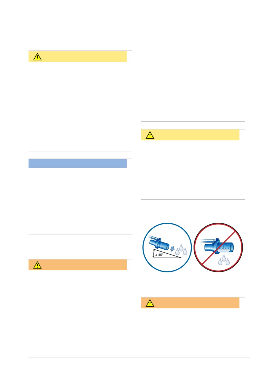
When using active humidification, pre-
vent water accumulation in the flow
sensor by ensuring that the flow sensor
NOTICE
is positioned at a ≥ 45° angle relative to
• To ensure that all breathing circuit
the floor. Excess water can affect the
connections are leak-tight, perform
flow sensor measurements and lead to
the Leak test every time you connect a
inaccurate volume delivery, potentially
circuit or change a circuit part.
resulting in hypoventilation.
• If there is a mismatch between the
selected patient group and the type
Figure 1-1. Position flow sensor at an angle
≥ 45° relative to the floor
of flow sensor connected, the calibra-
tion fails. Ensure you are using the
correct flow sensor for the patient.
1.6.3 Humidifier
WARNING
• Before using a humidifier, review the
Instructions for use as well as the
1.6.4 CO2 sensor setup and operation
Instructions for use provided with its
accessories.
• To prevent possible patient injury and
WARNING
equipment damage, do not turn the
• Monitor the CO2 waveform (capno-
humidifier on until the gas flow has
gram) on the ventilator display. If it
started and is regulated. Turn the
appears abnormal, check the patient,
humidifier off before stopping gas
settings, and the breathing circuit
flow.
Hamilton Medical | HAMILTON-T1 Operator's Manual
29
1 Safety information
components, including the CO2
•
For the CO2 sensor/adapter, use only
sensor sampling line. Adjust and
cleaning and disinfection agents that
replace components as appropriate.
are recommended in Table 12-4.
•
If the capnogram appears abnormal,
•
Periodically check the sensor and tub-
inspect the CO2 airway adapter and
ing for excessive moisture or secretion
replace if needed.
build-up, and replace if needed.
Excessive moisture can affect mea-
•
Elevated baseline can be caused by
surements.
sensor problems or by the patient's
condition.
•
LoFlo sidestream CO2 sensor.
Do not use with patients who cannot
•
Do not use any CO2 sensor/adapter if
tolerate the removal of 50 ml ±10 ml/
it appears to be damaged or if it fails
min from their total minute volume.
to operate properly. Refer servicing to
In adaptive modes (such as ASV,
Hamilton Medical authorized person-
nel.
APVcmv, and APVsimv), the removal is
fully compensated.
•
In NIV and neonatal ventilation with
•
LoFlo sidestream CO2 sensor.
uncuffed tubes, leaks may influence
Use of devices containing PVC plasti-
the capnogram and the measured
cized with DEHP should be limited to
values.
the amount of time treatment is med-
•
Always connect all components
ically necessary, especially for
securely and check for leaks according
neonates and pregnant or nursing
to standard clinical procedures.
mothers.
•
Positioning of tubes and cables:
- Do not position the cables or tubing
in any manner that may cause patient
CAUTION
entanglement or strangulation.
•
All devices are NOT protected against
- Support the tubing to avoid stress
reanimation with a defibrillator. Dis-
on the ET tube.
connect the CO2 sensor before using
- Do not apply excessive tension to
a defibrillator on the patient.
any cable or tubing.
•
Always use the correct CO2 airway
•
During use, a system leak, such as
adapter for the patient group.
that caused by an uncuffed ET tube or
In adult patients, smaller geometrics
damaged airway adapter, may signifi-
increase airway resistance and induce
low tidal volumes and AutoPEEP.
cantly affect sensor readings, includ-
ing flow, volume, pressure, and other
In neonatal patients, larger geomet-
respiratory parameters.
rics impede effective CO2 removal
and add dead space.
•
Leakages in the breathing or sampling
system may cause the displayed CO2
•
Do NOT place the CO2 sensor directly
on the patient's skin. It can burn the
values to be significantly under-
reported (too low).
skin as the sensor may reach a tem-
perature of 46°C (115°F).
•
Keep all cleaning agents away from
the CO2 sensor electrical connections.
30
English | 10103179/02 USA
Nebulization
1
• Do NOT use the CO2 components
1.6.5 Nebulization
when they are wet or have exterior
condensation. Condensation may
WARNING
harm the patient.
• Use during nebulization may influence
•
Nebulization of drugs can cause an
the CO2 measurements. In addition,
occlusion and increased resistance of
the medication can contaminate the
a connected expiratory filter or heat
sensor windows, causing the sensor
and moisture exchanger (HMEF).
to fail prematurely.
Check the filter frequently for
increased resistance or blockage.
• LoFlo sidestream CO2 sensor.
Remove the sampling kit sample cell
•
Connect the nebulizer in the inspira-
from the module when not in use.
tory limb according to your institu-
tion’s policy and procedures. Con-
• LoFlo sidestream CO2 sensor.
necting the nebulizer between the
Do NOT stick finger into the sample
flow sensor and the endotracheal
cell receptacle.
tube increases dead space and causes
incorrect volume measurements.
NOTICE
•
Pneumatic nebulization affects the
•
Position airway adapters with win-
delivered oxygen concentration.
dows in a vertical, not a horizontal,
•
Nebulization can affect the accuracy
position. This helps keep patient
of CO2 measurements.
secretions from pooling on the win-
•
The use of a pneumatic nebulizer
dows.
adds gas to the ventilator breathing
If pooling occurs, remove the adapter,
system, which can affect the accuracy
rinse with sterile water, and recon-
of volume or flow measurements.
nect.
•
Do not combine the neonatal CO2
airway adapter and the adult flow
CAUTION
sensor. Doing so can increase resis-
To prevent the expiratory valve from
tance, create artifact, or lead to
sticking due to nebulized medications,
hypoventilation, AutoPEEP, or overin-
regularly check and clean or replace the
flation.
expiratory valve membrane and/or the
•
Do not place the CO2 sensor/adapter
expiratory filter.
between the ET tube and any con-
nected adapter, as this may allow
patient secretions to enter the tubing
and block the adapter windows.
•
The CO2 sensors and accessories that
have contact with the patient are not
made with natural rubber latex.
•
Nitrous oxide, elevated levels of
oxygen, helium, and halogenated
hydrocarbons can influence the CO2
measurement.
Hamilton Medical | HAMILTON-T1 Operator's Manual
31
1 Safety information
NOTICE
1.7 Ventilating the patient
• Pneumatic nebulization is disabled:
This section provides the following safety
- During neonatal ventilation (if
information:
needed, use an Aerogen nebulizer3)
• Specifying patient settings
- When using HiFlowO2 therapy
• Neonatal ventilation
- When using LPO
• Only use approved piezo nebulizers
• Apnea backup
with the HAMILTON-T1.
• Noninvasive ventilation
1.6.6 Speaking valve
1.7.1 Specifying patient settings
CAUTION
WARNING
•
Do not leave the patient unattended
•
It is the clinician’s responsibility to
when SpeakValve is activated and a
ensure that all ventilator settings are
speaking valve is connected to the
appropriate, even when “automatic”
patient.
features, such as ASV, or default
settings are used.
•
When compatibility is activated:
•
To prevent possible patient injury:
- Apnea backup ventilation is dis-
abled.
- Make sure the ventilator is set up
When compatibility is turned off,
for the appropriate patient group
Apnea backup ventilation returns to
with the appropriate breathing circuit
its previous setting.
components.
- Some alarm limits are changed and
- For each patient group, make sure
some alarms are disabled. For details,
you select the correct patient sex and
see Section 10.8.4.
height (Adult/Ped) or weight (Neona-
tal). Correct entries help prevent
- Some changes apply to monitoring
hyper- or hypo-ventilation.
parameters. For details, see Section
10.8.3.
•
The ventilator is a high-flow device
that can operate with flows above 60
l/min and with a high oxygen concen-
tration.
3 Aerogen nebulization is not supported for patients younger than 28 days old in the USA.
32
English | 10103179/02 USA
Neonatal ventilation
1
1.7.2 Neonatal ventilation
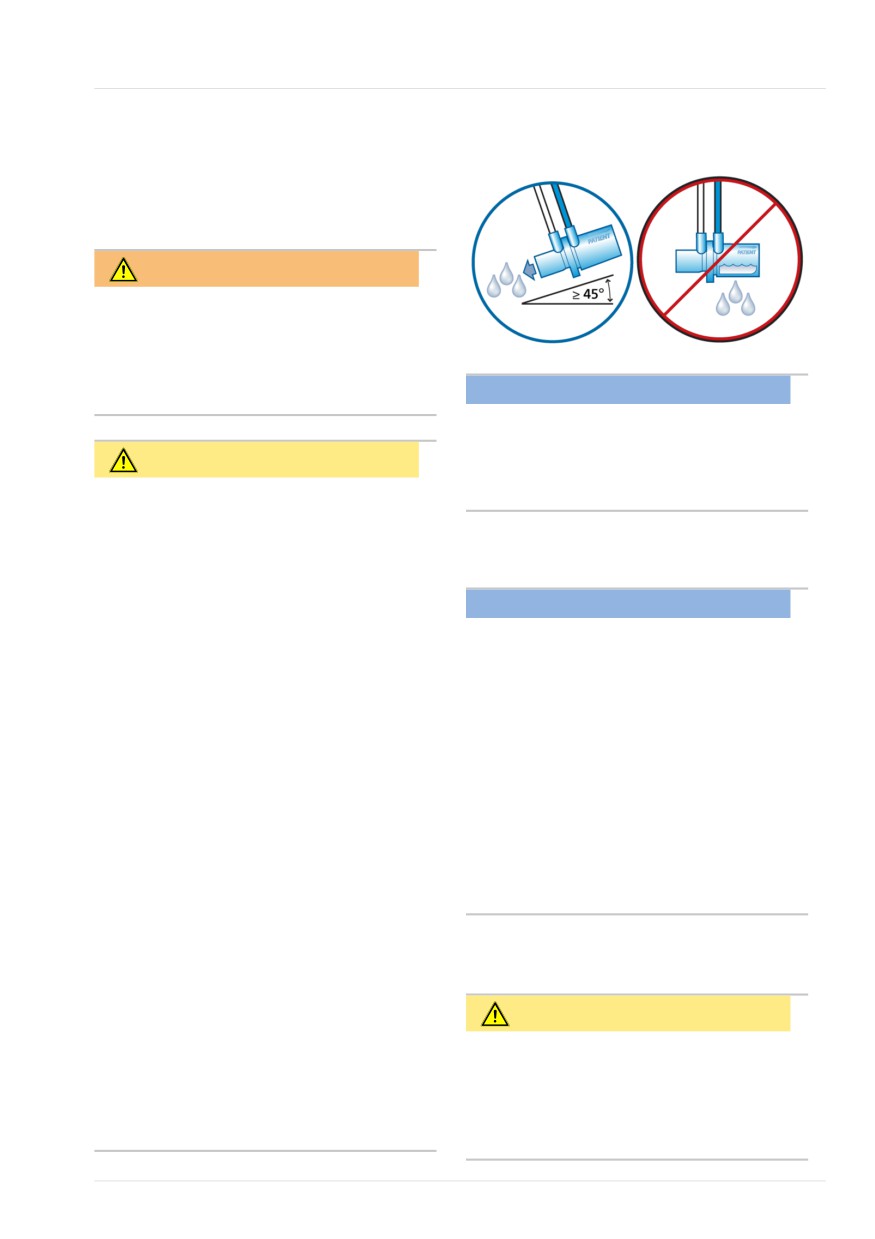
Figure 1-2. Position flow sensor at a ≥ 45°
angle relative to the floor
In addition to the information provided in
this section, carefully review the informa-
tion in Sections 1.6 and 1.7.
WARNING
Prolonged exposure to high oxygen con-
centrations may cause irreversible blind-
ness and pulmonary fibrosis in pre-term
neonates. Be especially careful when per-
NOTICE
forming oxygen enrichment.
When switching between the Adult/Ped
to the Neonatal patient groups, you must
CAUTION
calibrate the flow sensor and perform
•
Make sure the correct type of expira-
the Leak test.
tory valve for your patient is installed:
- Ensure the Neonatal patient group is
1.7.2.1 Working with nCPAP modes
selected on the ventilator when using
the neonatal expiratory valve. It
NOTICE
cannot be used with the Adult/Ped
group.
• In nCPAP and nCPAP-PC modes, start-
ing O2 enrichment or changing the
- You must use a neonatal expiratory
Oxygen setting sets the flow to 10 l/
valve for neonates.
min for 60 seconds. The flow then
•
To prevent increased CO2, do NOT use
returns to its previous setting.
an adult airway adapter for neonates
• The Flow sensor calibration needed
as it will increase dead space.
alarm may be generated when chang-
•
To determine appropriate tidal and
ing to and from nCPAP modes.
minute volumes for neonatal patients,
• Apnea backup, trigger detection, dis-
you must consider (anatomic) dead
connection detection, and volume
space. Artificial airways (for example,
measurements are not available in
Y-piece, flow sensor, ET tube, CO2
nCPAP modes.
airway adapter) increase the dead
space.
•
When using active humidification,
1.7.3 Apnea backup
prevent water accumulation in the
flow sensor by ensuring that the flow
CAUTION
sensor is positioned at a ≥ 45° angle
relative to the floor. Excess water can
We recommend you enable Apnea back-
affect the flow sensor measurements
up ventilation whenever a mode that
and lead to inaccurate volume deli-
allows spontaneous breathing is
very, potentially resulting in hypoven-
selected. Apnea backup is enabled by
tilation.
default.
Hamilton Medical | HAMILTON-T1 Operator's Manual
33
1 Safety information
1.7.4 Noninvasive ventilation
NOTICE
•
The HAMILTON-T1 is not intended to
NOTICE
be a comprehensive vital sign monitor
• As a precaution, while noninvasive
for patients on life-support equip-
ventilation is in use, you must be pre-
ment.
pared to intubate the patient and
Patients on life-support equipment
start invasive ventilation at any time.
should be appropriately monitored by
qualified medical personnel and suit-
• The use of a mask can increase dead
able monitoring devices.
space. Always comply with the mask
manufacturer’s instructions when
•
Do not pause the audible alarm when
using noninvasive ventilation.
leaving the patient unattended.
• The Inspiratory volume limitation alarm
•
The factory default alarm limit
is inactive in noninvasive modes.
settings are set in line with the
selected patient group, allowing for
unattended monitoring. These
1.8 Monitoring and alarms
settings, however, can never replace
individual review of the patient and
adjustment of alarm limits based on
CAUTION
their condition.
•
To prevent possible patient injury,
•
The use of an alarm monitoring
make sure the alarm limits are appro-
system does not give absolute assur-
priately set before you place the
ance of warning for every type of
patient on the ventilator.
issue that may arise with the ventila-
•
The HAMILTON-T1 oxygen monitoring
tor.
function can be disabled. Ensure that
Alarm messages may not pinpoint a
an alternative means of oxygen
problem exactly; the exercise of clini-
monitoring is always available and
cal judgment is necessary.
enabled to reduce the possibility of
•
It is recommended that additional
patient death or serious deterioration
independent monitoring devices,
of health.
including pulse oximeters measuring
•
To ensure that oxygen monitoring is
SpO2 and CO2 sensors, be used
always fully functional, replace an
during mechanical ventilation. The
exhausted or missing O2 sensor as
operator of the ventilator must still
soon as possible or use an external
maintain full responsibility for proper
monitor that complies with ISO
ventilation and patient safety in all sit-
80601-2-55.
uations.
•
Ambient temperature < 0°C: The
oxygen concentration that is displayed
may be inaccurate. Disable O2
monitoring. Ensure that an alternative
means of oxygen monitoring is always
available and enabled.
34
English | 10103179/02 USA
Using the trolley
1
• Alarm conditions, including technical
1.10.1 General maintenance, clean-
faults/events, that are not directly
ing, and disinfection
related to a physiological sensor
(CO2, SpO2) do not affect the func-
WARNING
tion of any attached physiological
sensor, including the values of any
•
Reprocessing of Hamilton Medical sin-
associated CO2, SpO2, and pulse-rate
gle-use products can affect the
measurements. Real-time waveforms
product properties and may cause
on the ventilator provide a method
injury to the patient. For example, a
for assessing the displayed numeric
change to the surface structure
values.
during reprocessing may lead to a
• The alarm limits Auto function is not
change in the tear strength or cause
available during neonatal ventilation.
actual cracking.
Furthermore, an altered surface struc-
ture may result in a microbial aggre-
1.9 Using the trolley
gation of spores, allergens, and pyro-
gens, for example, or cause an
increase in the number of particles
WARNING
released as a result of chemical
• To prevent possible personal injury
changes in the material properties.
and equipment damage, including
•
To reduce the risk of cross-contamina-
tipping:
tion, regularly clean and replace the
- Lock the trolley’s wheels when park-
fan filter. For details, see Table 12-5
ing the ventilator.
and Section 12.4.1.
- Take care when crossing thresholds.
•
To prevent patient exposure to steril-
izing agents and to prevent prema-
• To prevent accidental extubation,
ture deterioration of parts, sterilize
check the patient tubing support arm
parts using only the techniques rec-
joints and secure as necessary.
ommended in Chapter 12 and in any
associated Reprocessing guide or
1.10 Maintenance
Instructions for use provided with
each part.
This section provides the following safety
•
Hamilton Medical does not assume
information:
any liability for the proper functioning
• General maintenance, cleaning, and
of single-use items if they are repro-
disinfection
cessed and reused by the user.
•
Always use caution when handling
• Preventive maintenance
bacteria filters to minimize the risk of
• O2 sensor
bacterial contamination or physical
damage. Dispose of used filters imme-
diately after use. Follow your hospital
procedures for disposal.
Hamilton Medical | HAMILTON-T1 Operator's Manual
35
1 Safety information
•
Follow the cleaning, disinfection, and
• Cleaning and disinfection agent
sterilization procedures for each com-
residues can cause blemishes or fine
ponent as described in this guide and
cracks, especially on parts exposed to
in the cleaning agent manufacturer’s
elevated temperatures during steriliza-
Instructions for use.
tion.
•
Always disconnect the device and any
accessories, including CO2 sensor/
NOTICE
adapter, from electrical power before
cleaning and disinfection to reduce
For specific information on cleaning, dis-
the risk of electric shock.
infecting, and sterilizing autoclavable
(reusable) accessories and components,
refer to the appropriate Reprocessing
CAUTION
guide and Instructions for use provided
with each part.
•
Do NOT sterilize or immerse the CO2
sensor in liquids.
•
Do NOT attempt to sterilize the inte-
1.10.2 Preventive maintenance
rior components of the ventilator.
•
Do NOT attempt to sterilize the entire
NOTICE
device with ETO gas.
•
Dispose of all parts removed from the
•
Incorrect concentrations or residence
device according to your institution’s
times of sterilization agents may lead
protocols. Comply with all local, state,
to bacterial resistance.
and federal regulations with respect
•
To prevent premature deterioration of
to environmental protection, espe-
parts, make sure the disinfecting
cially when disposing of the electronic
chemical is compatible with the part
device or parts of it.
material. Use only EPA-registered/
•
We recommend that you document
approved cleaning and disinfection
all maintenance procedures.
solutions, as approved by your institu-
•
It is not allowed to perform service or
tion’s protocol, after each patient use,
maintenance on the device while a
according to the cleaning agent man-
patient is connected.
ufacturer's recommendations.
•
If no bacteria (inspiratory) filter is
•
Intrusion of fluids, or immersing parts
used, the device must be considered
in fluids, will damage the device.
contaminated and must be serviced.
•
Do NOT pour fluids onto the device
surfaces.
•
Do NOT use abrasives materials (for
example, steel wool or silver polish),
hard brushes, pointed instruments, or
rough materials on surfaces.
•
Thoroughly rinse all patient- or air-
way-contact components to ensure
removal of residual cleaning/disin-
fection agents.
36
English | 10103179/02 USA
O2 sensor
1
1.10.3 O2 sensor
1.11 Service and testing
•
To ensure proper servicing and to pre-
CAUTION
vent possible physical injury, only
Hamilton Medical authorized service
If an O2 sensor is not installed, use an
personnel may service the ventilator
external oxygen monitor complying with
using information provided in the venti-
ISO 80601-2-55 to verify that the set
lator Service Manual.
oxygen concentration is being delivered
In addition, all accessories and devices
to the patient. Be sure to cover the O2
must only be serviced by Hamilton
sensor port with the provided cover.
Medical authorized service personnel.
•
The manufacturer can only be responsi-
NOTICE
ble for the safety, reliability, and perfor-
•
Replace the O2 sensor with a genuine
mance of the ventilator if all of the
Hamilton Medical O2 sensor only;
following requirements are met:
otherwise, oxygen measurement will
- Appropriately trained personnel
not function and permanent oxygen-
carry out assembly operations,
related alarms may be generated.
extensions, readjustments, modifica-
•
To prevent leakage within the ventila-
tions, maintenance, or repairs.
tor, make sure an O2 sensor is
- The electrical installation of the rele-
installed at all times, even if you use
vant room complies with the appro-
an external monitor or disable oxygen
priate requirements.
monitoring.
- The ventilator system is used in
•
Keep the oxygen sampling site free of
accordance with the ventilator Oper-
other gases to avoid affecting oxygen
ator’s Manual.
sampling.
- Do not attempt service procedures
•
The paramagnetic O2 sensor can only
other than those specified in the
be calibrated while the ventilator is in
ventilator Service Manual.
Standby; calibration during ventilation
is not possible.
•
Any attempt to modify the ventilator
hardware or software without the
express written approval of Hamilton
Medical automatically voids all war-
ranties and liabilities.
Hamilton Medical | HAMILTON-T1 Operator's Manual
37
2
System overview
2.1
Overview
40
2.2
Physical descriptions
43
2.3
Turning the ventilator on and off
54
2.4
Navigating the windows and controls
55
39
2 System overview
2.1 Overview
• Support for pneumatic or Aerogen
nebulization
The HAMILTON-T1 ventilator system
• Support for AC and DC primary power
comprises the following main compo-
sources
nents:
• Remote viewing, reporting, and file
• Ergonomic design featuring integrated
transfer using the Hamilton Connect
monitor with touch screen display and
App on supported smartphones and
integrated alarm lamp
mobile devices4
• Ventilation unit for gas mixing and
control, and patient breathing circuit
2.1.1 Standard features and options
for gas delivery and exchange
The ventilator offers a robust set of stan-
• Oxygen monitoring using a galvanic
dard equipment and features, as well as
sensor
optional modes and features for the sup-
• Optional communication with smart-
ported patient groups.
phones and integration with hospital
network
Table 2-1 lists the standard software confi-
guration and options.
• Optional connections to a humidifier,
nebulizer, SpO2 and CO2 sensors, and
Table 2-2 lists the standard equipment
external data interfaces
(hardware) and options.
• Trolley, carrying case, and a variety of
wall, bed, ceiling, and shelf mounts
The ventilator system offers the following
main features:
• Monitoring: Real-time waveforms,
numerical monitoring, trends, loops,
and Intelligent panels showing the
patient’s real-time breathing status,
ventilator dependence, and targets,
CO2 and SpO2 measurements (when
enabled)
• Alarms and on-screen troubleshooting
help
• Configurable startup settings for each
patient group
• Remote access to the HAMILTON-H900
humidifier controls and status
4 Not available in all markets.
40
English | 10103179/02 USA
Standard features and options
2
Table 2-1. Standard software configuration and options
Function
Patient group
Adult/Ped
Neonatal5, 6
Standard: X Option: O Not applicable: --
Patient groups
X
O
Modes
Intelligent ventilation mode
ASV®
X
--
Volume-targeted, pressure-controlled modes
APVcmv / (S)CMV+
X
X
APVsimv / SIMV+
X
X
Pressure-controlled modes
DuoPAP, APRV
O
O
PCV+
X
X
PSIMV+
X
X
SPONT
X
X
Noninvasive modes
NIV, NIV-ST
O
O
nCPAP, nCPAP-PC
--
O
Other functions
On-screen help
X
X
CPR ventilation
X
X
Suctioning tool
X
--
Flow trigger
X
X
HiFlowO2
O
O
Speak valve compatibility
O
O
Hamilton Connect Module
O
O
Trends/Loops
O
O
5 Applies only to devices with serial number > 3000.
6 Not available in all markets.
Hamilton Medical | HAMILTON-T1 Operator's Manual
41
2 System overview
Table 2-2. Standard equipment (hardware) configuration and options
Functions
HAMILTON-T1
Standard: X Option: O
Trolley, carrying case, and a variety of wall, bed, ceiling, and shelf
O
mounts
Second battery
O
Communication board:
O
CO2/Nurse Call/COM, CO2/SpO2/COM7, CO2, or
CO2/SpO2/Humidifier & COM18
USB port
X
RJ-45 Ethernet port9
X
Communication protocols:
O
Hamilton, Hamilton P2, GALILEO compatible, DrägerTestProtocol,
Philips VueLink Open, Hamilton Block protocol
HAMILTON-H900 humidifier integration
O
Night vision compatibility (NVG)7
O
NBC filter compatibility
O
7 Applies only to devices with serial number > 3000.
8 RS-232 connection over the
/COM1 port is only available when using the communication Y-cable (PN 10077038).
9 Only available for use if the Hamilton Connect Module is activated.
42
English | 10103179/02 USA
Physical descriptions
2
2.2 Physical descriptions
This section provides an overview of the
ventilator, breathing circuit sets, and
trolley.
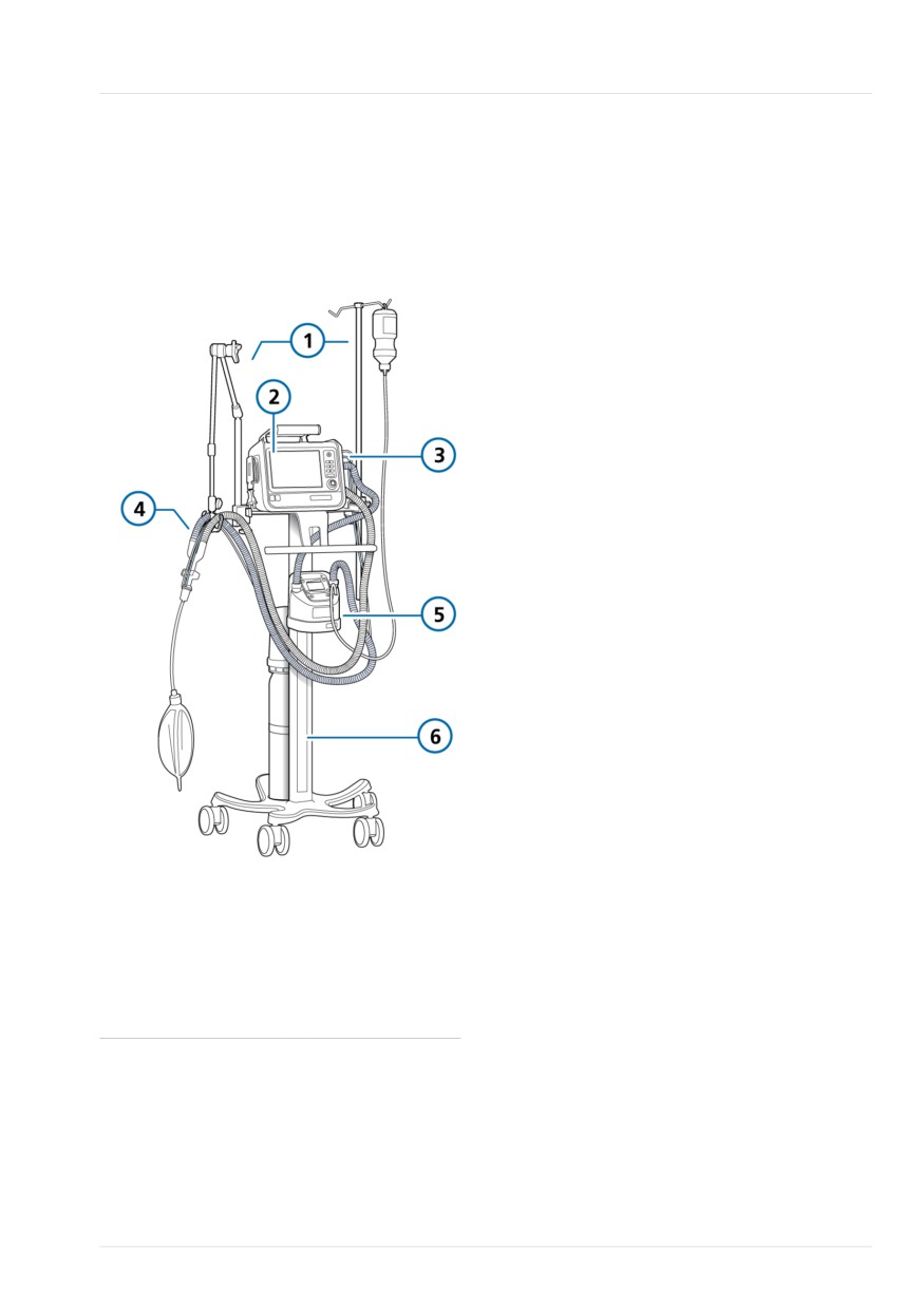
Figure 2-1. HAMILTON-T1 with accessories
1
Support arm and
4
Breathing circuit
infusion arm
2
Display and
5
Humidifier
controls
3
Breathing circuit
6
Trolley
connections
Hamilton Medical | HAMILTON-T1 Operator's Manual
43
2 System overview
2.2.1 About the ventilator
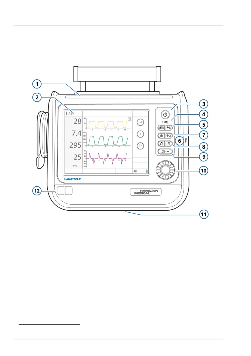
Figure 2-2. Front view, ventilator
1
Alarm lamp
7
Manual breath key/O2 enrichment key
2
Touch screen display
8
Print screen key/Nebulizer key
3
Power/Standby key
9
Audio pause key
4
Battery charge indicator
10
Press-and-Turn (P&T) knob
5
Day/Night key10/Screen lock/unlock key
11
Expiratory valve bleed port (under the
ventilator) Do not obstruct
6
Near-field communication (NFC)
12
Front cover and battery
connection area11
10 Applies only to devices with serial number > 3000.
11 May not be available on older devices. Contact your Hamilton Medical technical representative for details.
44
English | 10103179/02 USA
About the ventilator
2
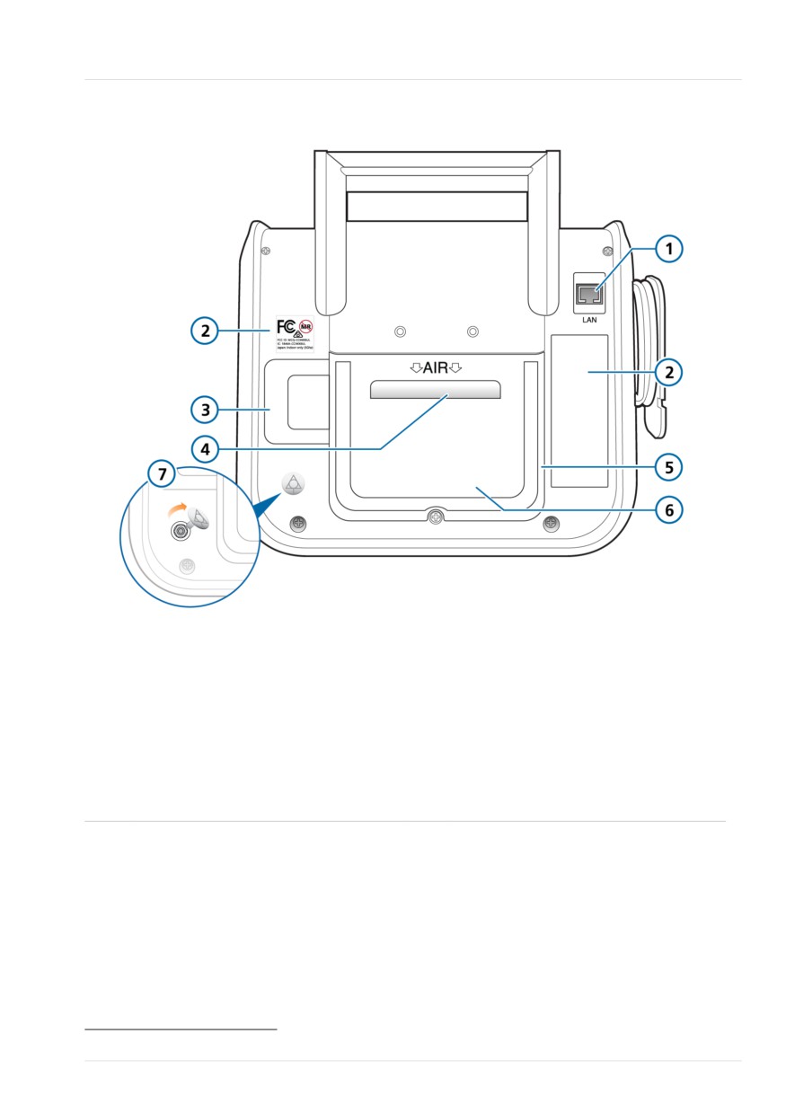
Figure 2-3. Rear view, ventilator
1
RJ-45 Ethernet connector (under the
5
Rear cover
cover)
2
Device labels
6
HEPA filter (under the cover)
3
O2 sensor (under the cover)
7
Potential equalization conductor with
cover12
4
Air intake and dust filter Do not
obstruct
12 May not be available on older devices. Contact your Hamilton Medical technical representative for details.
Hamilton Medical | HAMILTON-T1 Operator's Manual
45
2 System overview
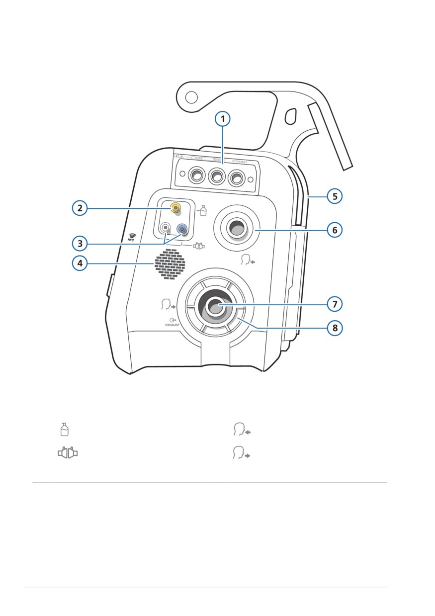
Figure 2-4. Side view, with breathing circuit connections
1
Communication board
5
Cooling air outlet
(optional)
2
Pneumatic nebulizer port
6
To patient inspiratory port
3
Flow sensor connection ports
7
From patient expiratory port
4
Loudspeaker
8
Expiratory valve set
46
English | 10103179/02 USA
//////////////////////////////////////////