HAMILTON-T1. Operator's Manual (2022) - page 2
About the ventilator
2
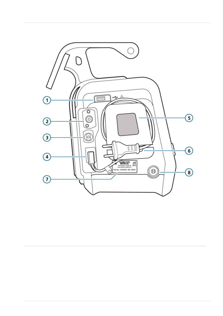
Figure 2-5. Side view, with gas connections
1
USB port (under the cover)
5
Cooling air intake and dust filter
2
High-pressure oxygen DISS or NIST inlet
6
AC power cord with retaining clip
fitting
3
Low-pressure oxygen connector
7
Serial number label
4
AC Power socket
8
DC power socket
Hamilton Medical | HAMILTON-T1 Operator's Manual
47

2 System overview
2.2.2 About the main display
Figure 2-6. Main display
1
Patient group symbol and active mode
7
Power source and battery status
2
Message bar (color coded)
8
Audio pause indicator and countdown
timer**
3
Configurable graphic display (full-length
9
Humidifier quick access icon
waveforms shown)
4
Modes button
10
Measured SpO2 value*
5
Main controls for the active mode
11
Main monitoring parameters (MMP)
6
Window buttons: Alarms, Controls,
12
Date and time
Monitoring, Tools, Events, System
* When SpO2 monitoring is enabled.
** When Audio pause is active, the connectivity icons are not displayed. See Table 2-3.
48
English | 10103179/02 USA
About the patient breathing circuits
2
2.2.3 About the patient breathing
circuits
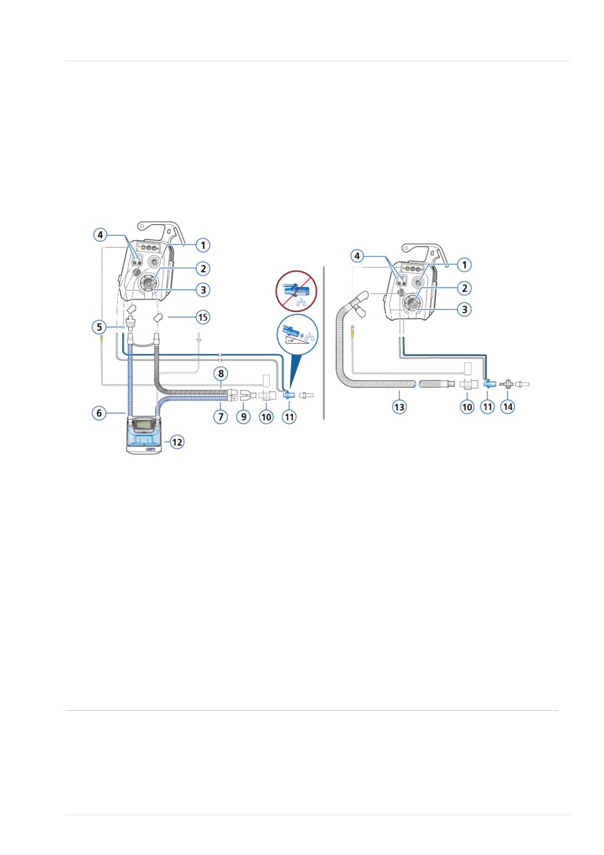
Figure 2-7. Adult/pediatric breathing circuits
Adult/Ped: Dual limb with humidifier
Adult/Ped: Coaxial with HMEF
1
To patient inspiratory port
9
Y-piece
2
From patient expiratory port
10
CO2 sensor/adapter
3
Expiratory valve set
11
Flow sensor
4
Flow sensor connection ports
12
Humidifier
5
Bacteria filter
13
Coaxial inspiratory/expiratory limb
6
Inspiratory limb to humidifier
14
HMEF
7
Heated inspiratory limb with tempera-
15
Adapters
ture sensor, to patient
8
Heated expiratory limb
Some connection adapters may be required, but are not shown. Refer to the breathing circuit
Instructions for use.
Hamilton Medical | HAMILTON-T1 Operator's Manual
49
2 System overview
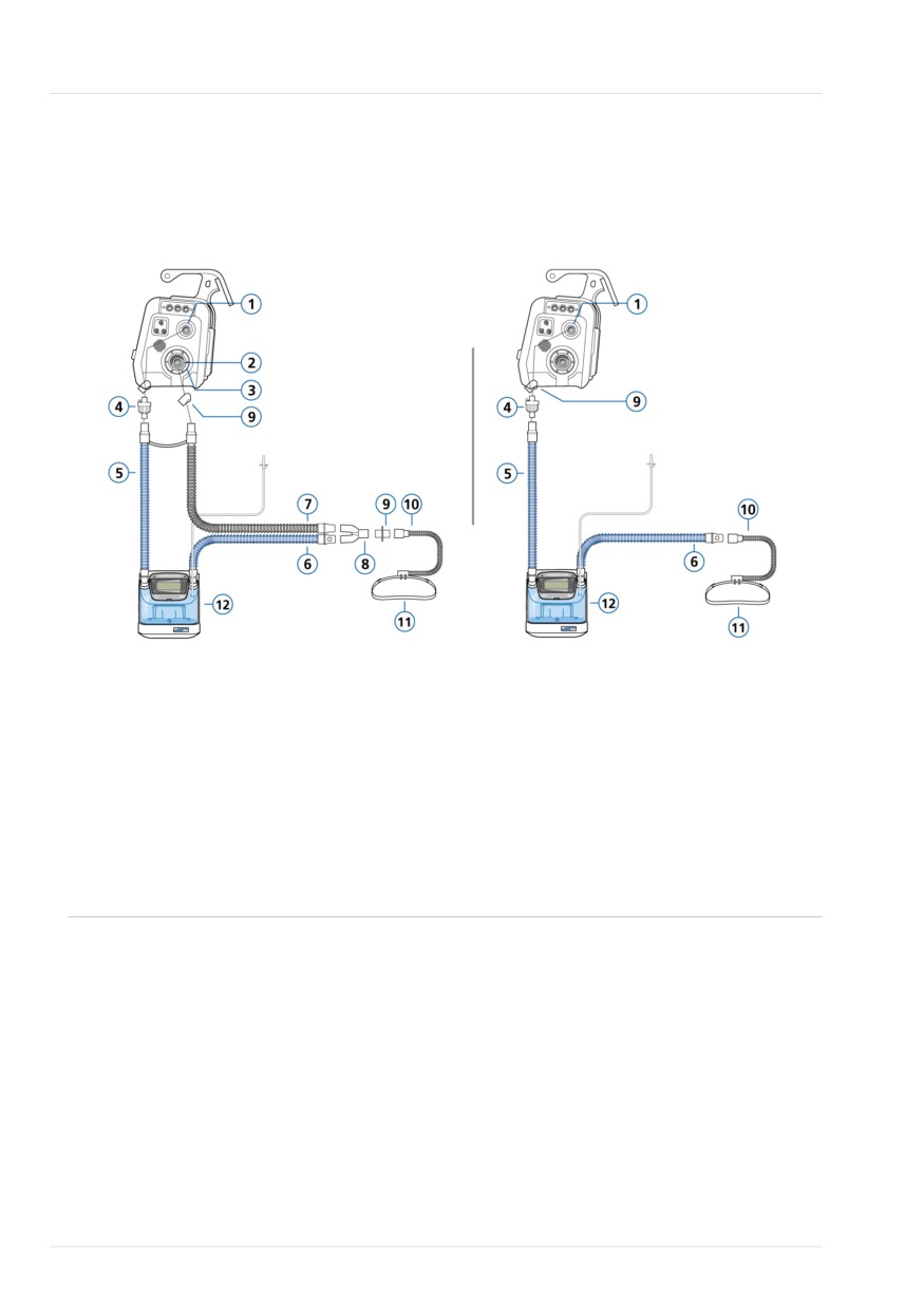
Figure 2-8. Adult/pediatric breathing circuits: high flow oxygen therapy
Adult/Ped: Dual limb, high flow oxygen
Adult/Ped: Single limb, high flow
therapy
oxygen therapy
1
To patient inspiratory port
7
Heated expiratory limb
2
From patient expiratory port
8
Y-piece
3
Expiratory valve set
9
Adapters (various)
4
Bacteria filter
10
Nasal cannula
5
Inspiratory limb to humidifier
11
Attachment strap
6
Heated inspiratory limb with tempera-
12
Humidifier
ture sensor, to patient
50
English | 10103179/02 USA
About the patient breathing circuits
2
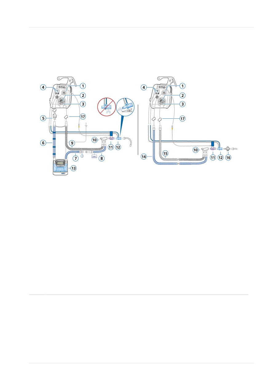
Figure 2-9. Neonatal breathing circuits
Neonatal/pediatric: Dual limb with
Neonatal/pediatric: Dual limb with HMEF
humidifier
1
To patient inspiratory port
10
Y-piece
2
From patient expiratory port
11
CO2 sensor/adapter
3
Expiratory valve set
12
Flow sensor
4
Flow sensor connection ports
13
Humidifier
5
Bacteria filter
14
Inspiratory limb
6
Inspiratory limb to humidifier
15
Expiratory limb
7
Heated inspiratory limb with temperature sensor,
16
HMEF
to patient
8
Unheated inspiratory limb extension, for use in
17
Adapters (various)
incubator
9
Heated expiratory limb
Hamilton Medical | HAMILTON-T1 Operator's Manual
51
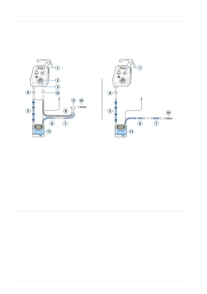
2 System overview
Figure 2-10. Neonatal breathing circuits: high flow oxygen therapy
Neonatal/pediatric: Dual limb, high flow
Neonatal/pediatric: Single limb, high flow
oxygen therapy
oxygen therapy
1
To patient inspiratory port
7
Unheated inspiratory limb extension,
for use in incubator
2
From patient expiratory port
8
Heated expiratory limb
3
Expiratory valve set
9
Y-piece
4
Bacteria filter
10
Connection to patient interface (options
not shown)
5
Inspiratory limb to humidifier
11
Humidifier
6
Heated inspiratory limb with tempera-
12
Adapters (various)
ture sensor, to patient
52
English | 10103179/02 USA
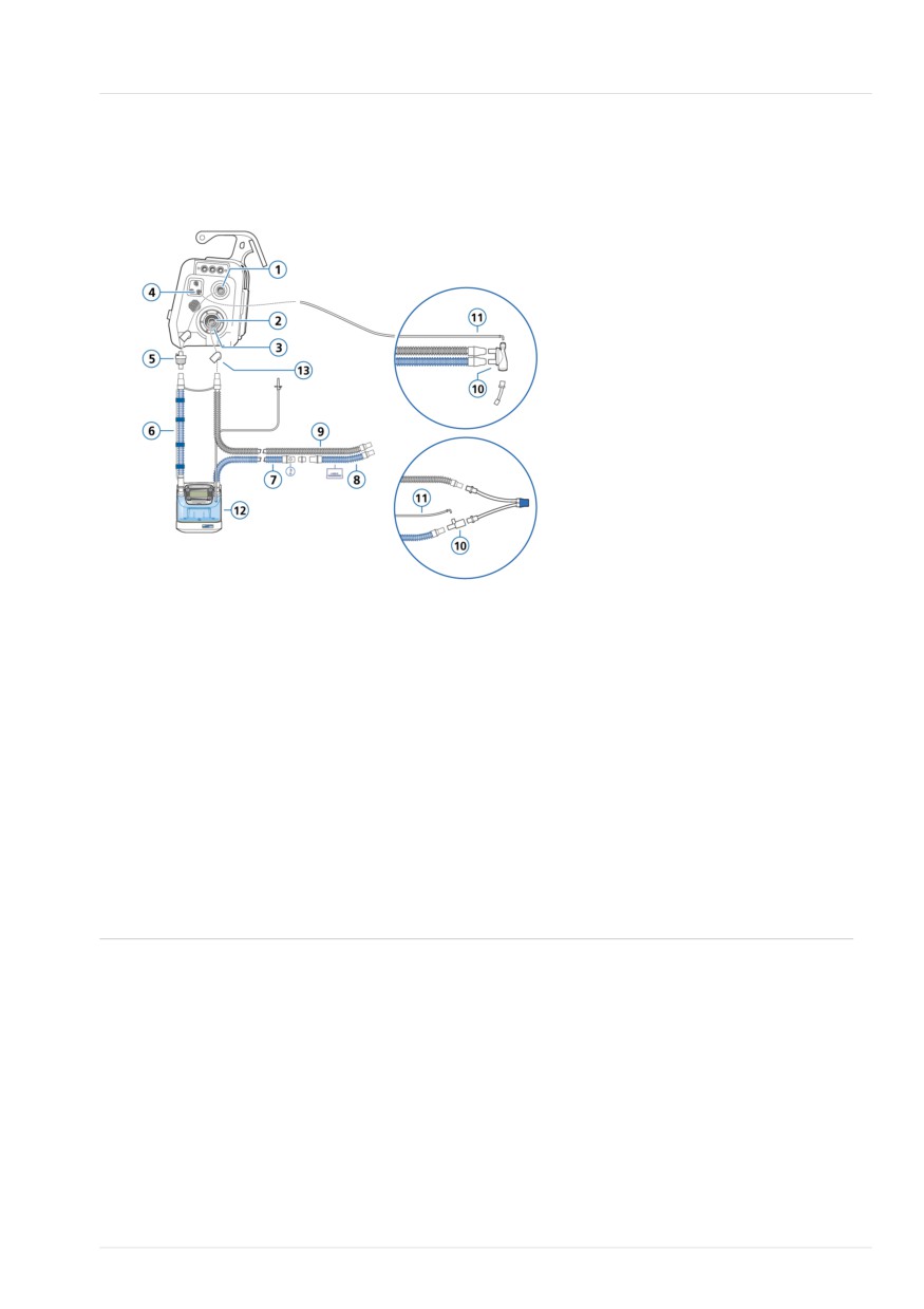
About the patient breathing circuits
2
Figure 2-11. Neonatal breathing circuit: nCPAP, nCPAP-PC
Neonatal: nCPAP, nCPAP-PC
1
To patient inspiratory port
8
Unheated inspiratory limb extension,
for use in incubator
2
From patient expiratory port
9
Heated expiratory limb
3
Expiratory valve set
10
Y-piece, T-piece
4
Pressure line connection port (blue)
11
Pressure line
5
Bacteria filter
12
Humidifier
6
Inspiratory limb to humidifier
13
Adapters (various)
7
Heated inspiratory limb with temperature sensor, to patient
Hamilton Medical | HAMILTON-T1 Operator's Manual
53
2 System overview
2.2.4 About the trolley and mounting
- CO2 sensor (mainstream or side-
variations
stream)
- O2 cylinder
The HAMILTON-T1 can optionally be
- SpO2 sensor, including Masimo
ordered with a standard trolley, carrying
adapter
case, or a variety of wall, bed, ceiling, and
shelf mount solutions. The trolley has
- Humidifier
space for one oxygen cylinder.
2.3 Turning the ventilator on
2.2.4.1 Preparing the trolley for intra-
and off
hospital transport
To ensure the Event log records all events
Before proceeding, review the safety
properly, do the following:
information in Chapter 1.
• When entering Standby, wait at least
30 seconds before turning off the
WARNING
ventilator.
• Only the components listed in this
• After turning off the ventilator, wait at
section are approved for intrahospital
least 3 seconds before turning the
transport.
ventilator back on.
• Use of additional items, such as a tub-
ing support arm, can result in the
To turn on the ventilator
trolley tipping over.
4 Press
(Power/Standby).
• The ventilator must be attached to
the trolley using the locking bolt.
The ventilator runs a self-test. After a
Ensure the device is securely attached
short time, the Standby window is display-
to the trolley before use.
ed.13
If using a HAMILTON-T1 trolley, the venti-
Proceed with setting up the ventilator and
lator and its components, as well as the
patient, as appropriate.
trolley, must be configured and positioned
as follows during transport within the hos-
If the startup process does not complete
pital:
successfully when turning on the ventila-
tor, proceed as follows.
• The ventilator and oxygen cylinders
must be securely attached to the
To turn on the ventilator if startup is not
trolley.
successful
1. Turn off the ventilator by pressing and
• Only the following components are
allowed to be connected during trans-
holding
for about 10 seconds.
port:
2. Turn the ventilator on again by press-
- Breathing circuit
ing
- Tubing support arm
– Flow sensor (or pressure line)
13 For devices with serial number > 3000, startup time is ≤ 30 seconds. For devices with a lower serial number, startup time is ≤ 50
seconds.
54
English | 10103179/02 USA

Navigating the windows and controls
2
Figure 2-12. Power/Standby key (1)
2.4.1 Accessing windows
To open a window
4 Do any of the following to open a
window:
- Touch the button and any needed
tabs.
To turn off the ventilator
- Turn the P&T knob to move the
1. Press
(Power/Standby) to open the
cursor to the button or tab, then press
Activate Standby window during active
the P&T knob.
ventilation.
To close a window
2. Touch Activate standby to confirm.
4 Do any of the following to close a
The ventilator enters Standby.
window:
3. Press and hold
for about
- Touch the window button again.
3 seconds to turn off the ventilator.
- Touch the X button.
- Turn the P&T knob to move the
The ventilator turns off.
cursor to the X button, then press the
In the event of a technical fault or the
P&T knob.
device will not turn off
2.4.2 Adjusting controls
4 Press and hold for about
10 seconds to turn off the ventilator.
Specifying settings involves activating a
control, adjusting a value, and confirming
the setting.
2.4 Navigating the windows
and controls
To adjust a control setting
1. Activate the control by doing any of
Use the touch screen and the Press-and-
the following:
turn knob (referred to as the P&T knob) to
access data and specify settings.
- Touch the control to select and acti-
vate it; the selected control has a yel-
You interact with the HAMILTON-T1 user
low outline.
interface as follows:
- Turn the P&T knob to move the
• Touch elements on the display to open
cursor to the control; the selected
windows and make and confirm selec-
control has a yellow outline. Press the
tions.
P&T knob to activate it.
• Use the P&T knob to select, specify,
The activated control is orange (Figure
and confirm selections. A selected item
2-13).
is highlighted in yellow.
2. Adjust the value by turning the P&T
knob to increase or decrease the
This section describes how to navigate the
value. The orange dot indicates the
interface.
dynamic limit.
Hamilton Medical | HAMILTON-T1 Operator's Manual
55

2 System overview
3. Confirm the setting by doing any of
2.4.3 Selecting list items
the following:
Some selections are presented in a scrol-
- Touch the control again.
lable list.
- Press the P&T knob.
To select a list item
The new setting is immediately applied.
1. In a list, touch the scroll bar to select
Figure 2-13. Control status: activated
and activate it.
2. Turn the P&T knob to scroll through
the list, and when the desired selec-
tion is highlighted, press the knob to
select it.
2.4.4 Using shortcuts
The ventilator provides shortcuts for some
key functions.
Table 2-3. Shortcuts
Touch Quick
To display the ...
access icon/
shortcut on
main display ...
Controls > Patient window
,
, or
Active mode
Modes window
(top left of
display)
Any MMP
Alarms > Limits 1 window
SpO2 value
Alarms > Limits 2 window
(under MMPs)
Any graphic
Graphics selection
(waveform,
window
loop, trend,
Intelligent panel)
56
English | 10103179/02 USA

Using shortcuts
2
Touch Quick
To display the ...
access icon/
shortcut on
main display ...
System > Info 1 window
(any displayed
battery icon)
System > Settings > Date
& Time window
Alarms > Buffer window
or
Alarm message
On-screen alarm trouble-
in the Alarms >
shooting help
Buffer window
System > Settings >
Humidifier window14
System > Settings >
Connectivity window
(any connectivity
When an Audio pause is
icon15)
active, the connectivity
icons are not displayed.
14 If connected to the
/COM1 port on the ventilator.
15 If the option is installed. Not available in all markets.
Hamilton Medical | HAMILTON-T1 Operator's Manual
57
3
Preparing the ventilator
3.1
Overview
60
3.2
Connecting to a power source
60
3.3
Connecting the oxygen supply
63
3.4
Ensuring an adequate oxygen supply for patient transport
64
3.5
Setting up the patient breathing circuit
70
59
3 Preparing the ventilator
To connect the ventilator to a primary
3.1 Overview
power supply
Preparing the ventilator for use comprises
4 Connect the ventilator to an outlet
the following steps:
that supplies AC or DC power.
To ...
See ...
Make sure the power cord is well
seated into the ventilator socket and
Connect to a power
Section 3.2
secured with the power cord retaining
source.
clip to prevent unintentional discon-
Connect the oxygen
Section 3.3
nection.
supply.
Set up the patient breath-
Section 3.5
3.2.1 Connecting to DC power
ing circuit, including per-
Before proceeding, review the safety
forming the preopera-
information in Chapter 1.
tional check.
The DC cable can be used during trans-
Connect external devices
Chapter 4
port in ambulances, fixed-wing aircraft,
and sensors.
helicopters, and ships that provide an
Turn on the ventilator.
Section 2.3
appropriate electrical power supply.
Select the patient group,
Chapter 5
A DC cable kit (referred to as the assem-
mode, and alarm limits,
bled DC cable) includes a stripped end
and enter patient data.
with two strands. This cable must only be
assembled by authorized personnel using
a UL-listed plug.
3.2 Connecting to a power
The DC car cable is intended for use
during transport in ambulances and other
source
rescue vehicles that are provided with
Before proceeding, review the safety
appropriate plug connectors.
information in Chapter 1.
For available cables, see Chapter 14.
Always check the reliability of the primary
power outlet before plugging in the venti-
lator. The charge icon above the battery
shows that the ventilator is plugged in and
the batteries are charging.
60
English | 10103179/02 USA

Working with the potential equalization conductor
3
3.2.2 Working with the potential
3.2.3 Using battery power
equalization conductor
A mandatory backup battery protects the
The potential equalization conductor16 is
ventilator from low power or failure of the
located on the back of the ventilator. See
primary power source.
Figure 3-1.
When the primary power source fails, the
Consider using the potential equalization
ventilator automatically switches to opera-
conductor when working with a CO2
tion on backup battery with no interrup-
sensor, SpO2 sensor, or similar medical
tion in ventilation. An alarm sounds to sig-
devices.
nal the switch-over. Silence the alarm to
confirm notification of the power system
The potential equalization conductor must
change and reset the alarm.
not be used as a protective earth connec-
tion.
If battery power is completely lost, a
buzzer sounds continuously for at least
To connect the potential equalization con-
two minutes.
ductor
Batteries are charged whenever the venti-
1. Connect one end of a grounding
lator is connected to primary power,
cable to the potential equalization
whether or not it is turned on. The battery
conductor.
indicator on the device (Figure 2-2) shows
2. Connect the other end to a properly
the charge status of the batteries.
grounded outlet.
The battery and power source symbols in
When not in use, a cover can be placed
the bottom right corner of the display
over the conductor.
show the power source in use. See Table
3-1.
Figure 3-1. Potential equalization conductor
with cover (1)
An optional second battery is available. It
is shown on the display when installed.
16 The potential equalization conductor is designed for the connection of a potential equalization conductor according to DIN 42801
and IEC 60601-1. The function of the potential equalization conductor is to equalize potentials between the ventilator system and
other medical devices that can be touched simultaneously.
Hamilton Medical | HAMILTON-T1 Operator's Manual
61
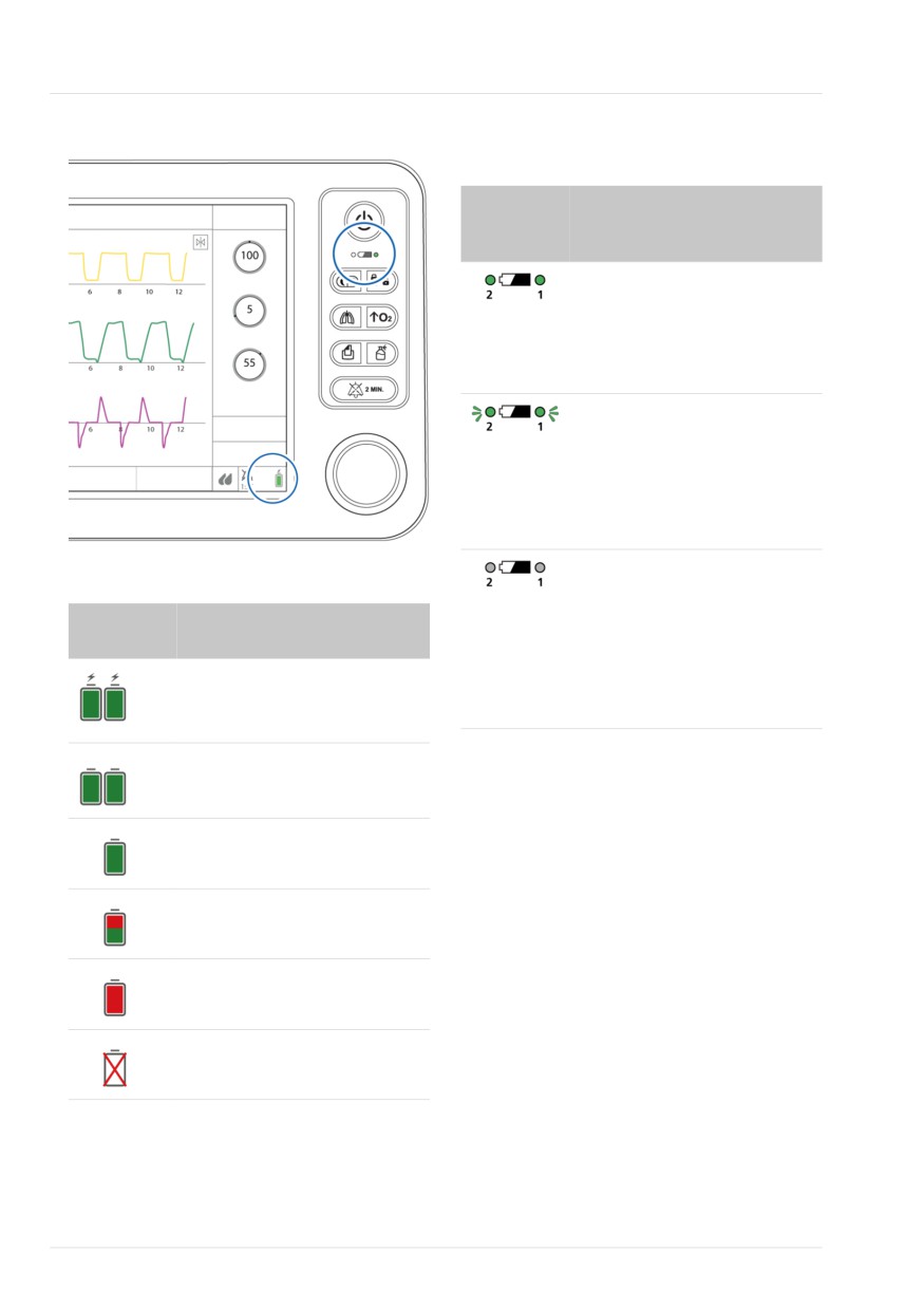
3 Preparing the ventilator
Figure 3-2. Power source indicators on display
Table 3-2. Battery charge indicator on ventila-
tor, overview
Indicator
Battery status
on ventila-
tor
Solid green: The indicated bat-
tery (1 shown) is fully charged
and the device is connected to
primary power, even when the
ventilator is turned off.
Flashing green: Flashes to
show that the device is con-
nected to a primary power
source and the indicated bat-
tery is charging, even when
the ventilator is turned off.
Not lit: Dark to show the indi-
Table 3-1. Battery/power state
cated battery is not charging
Power icon Battery status
(the device is running on bat-
on display
tery power and is not con-
nected to a primary power
Device is plugged into primary
source or the battery is over-
power and the battery is
heated).
charging.
Device is running on battery
If a battery is not fully charged, recharge it
power.
by connecting the ventilator to AC or DC
power. For details, see Section 15.4.
Battery is fully charged.
Chapter 12 describes how to replace the
battery.
Battery is partially charged.
Battery has less than 10%
charge left.
Battery is either defective or
not installed.
62
English | 10103179/02 USA

Connecting the oxygen supply
3
3.3 Connecting the oxygen
See Section 3.3.3 for details on selecting
the oxygen source on the device.
supply
Before proceeding, review the safety
3.3.3 Selecting the oxygen source
information in Chapter 1.
type
Oxygen for the HAMILTON-T1 can be pro-
Before starting ventilation, be sure to
vided by a high- or low-pressure source.
select the appropriate oxygen source. By
default, the ventilator is set to high-pres-
High-pressure oxygen, provided by a cen-
sure oxygen (HPO).
tral gas supply or a gas cylinder, is sup-
plied through DISS or NIST male gas fit-
You set the source in Standby.
tings. With the optional cylinder holder,
you can mount an oxygen cylinder to the
To select the oxygen source
trolley. If you use gases from the cylinder,
1. In Standby mode, touch Tools > Utili-
secure the cylinder to the trolley with the
ties.
accompanying straps.
2. Touch the appropriate button for the
Low-pressure oxygen is provided by a con-
desired oxygen source.
centrator or liquid cylinder.
- Select HPO mode for high-pressure
oxygen (default).
The selected setting is active until manu-
ally changed or the ventilator is restarted.
- Select LPO mode for low-pressure
oxygen (see Section 3.3.1).
3.3.1 Using a low-pressure oxygen
3. Close the window.
supply
Figure 3-3. Selecting the oxygen source
Using the low-pressure oxygen supply17
involves two steps:
• Connecting the supply to the ventilator
(Section 3.3.2)
• Selecting the source type on the venti-
lator (Section 3.3.3)
3.3.2 Connecting the oxygen supply
to the ventilator
To connect the oxygen supply to the venti-
lator
4 Connect the oxygen hose to the
1
Tools
3
HPO mode,
HAMILTON-T1's high-pressure or low-
LPO mode
pressure oxygen inlet fitting (Figure
2
Utilities
2-5).
17 Not available in all markets.
Hamilton Medical | HAMILTON-T1 Operator's Manual
63
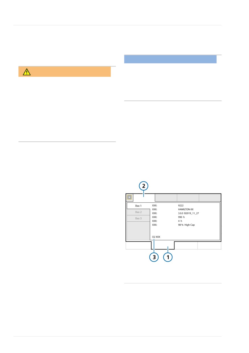
3 Preparing the ventilator
3.4 Ensuring an adequate
3.4.1 Reviewing current oxygen
consumption
oxygen supply for patient trans-
port
NOTICE
• O2 consumption data is not available
WARNING
with low-pressure oxygen (LPO).
Before transporting the patient, ensure
• When initially starting ventilation, the
an adequate oxygen supply by checking
O2 consumption parameter is calcu-
the O2 consumption parameter (in the
lated and displayed after 2.5 minutes.
System > Info window) and ensuring it is
adequate for your estimated travel time
The current oxygen consumption rate is
and current oxygen capacity.
displayed in the O2 consumption para-
meter in the System > Info window (Figure
Use the appropriate calculation method
3-4).
(see Table 3-3) to estimate total oxygen
requirements for the patient.
The O2 consumption rate is updated every
breath and shows the average rate over
Before transporting the patient you must
the last five minutes, after the initial 2.5
ensure that you have enough oxygen for
minutes of ventilation.
the journey.
Figure 3-4. System > Info window, O2
Be sure to:
consumption
• Review current oxygen consumption
(Section 3.4.1)
• Calculate the patient's estimated
oxygen requirement (Section 3.4.2)
For neonatal patients, use Method III
(Section 3.4.2.3).
For information about estimated oxygen
consumption relative to minute volume,
see Section 15.12.3.
1
System
3
O2 consumption
2
Info
64
English | 10103179/02 USA
Calculating estimated oxygen consumption
3
3.4.2 Calculating estimated oxygen
Table 3-3. Overview of O2 consumption calcu-
lation methods
consumption
For ...
Applicable for ...
See ...
WARNING
Method I
Smaller patients:
Section
The oxygen consumption of a nebulizer
≤ 70 cm,
3.4.2.1
attached to the device is not included in
IBW ≤ 8 kg
the O2 consumption parameter value. To
Method II
Larger patients:
Section
calculate it, use Method IV (Section
> 70 cm,
3.4.2.2
3.4.2.4).
IBW > 8 kg
Method III
Neonates:
Section
NOTICE
3.4.2.3
Patient group on
• The oxygen consumption calculation
the ventilator is set
is not intended to affect therapy
to Neonatal.
decisions and should be used solely
to estimate the amount of oxygen
Method IV
Additional amount
Section
required for the duration of transport,
(nebulizer
to add to the
3.4.2.4
before connecting the ventilator to
in use)
result of Method I
the patient.
or II to account for
the nebulizer
• The calculations provided here are
oxygen use.
valid only for systems without leaks
at the patient end.
For systems with leaks (for example,
All of the methods require the following
ventilating with a mask), oxygen
information for the calculation:
consumption will be higher.
• ExpMinVol setting (l/min)
• The calculations show the result in
liters per minute (l/min). You must
• Oxygen setting (%)
multiply the result by the planned
• I:E setting, if using a nebulizer
duration of transport for the final
estimate.
• Planned duration of transport
The calculation method for estimating
The patient height and IBW (or Weight for
oxygen consumption depends on the
neonatal patients) determine which of the
patient height and weight, and nebulizer
calculation methods to use (Table 3-3).
use, as listed in the following table.
Hamilton Medical | HAMILTON-T1 Operator's Manual
65
3 Preparing the ventilator
3.4.2.1 Method I. Overall oxygen
consumption for smaller patients
Method I is for smaller patients with
height ≤ 70 cm, IBW ≤ 8 kg, in liters per
minute (l/min).
For neonatal patients, use Method III18
(Section 3.4.2.3).
Table 3-4. Calculating O2 consumption using Method I for smaller patients
Calculation
Result and example
To calculate estimated oxygen consumption using Method I:
O2 cons. = [(ExpMinVol * 2) + 3 l/min] * [(FiO2 - 20.9) / 79.1]
1
Replace ExpMinVol
Example uses:
and FiO2 in the equa-
ExpMinVol = 2 l/min
tion with the current
Oxygen (FiO2) = 60%
patient values.
2
Solve the equation.19
The result is the estimated oxygen consumption in liters per minute
(l/min).
Example.
O2 consumption = ((2 * 2) + 3) * (60 - 20.9) / 79.1
O2 consumption = 7 * 0.494
O2 consumption = 3.5 l/min
3
Multiply the result by
The final result is the estimated oxygen requirement, in liters, for
the planned duration
the specified length of time.
of transport, in
Example.
minutes.
Transport duration = ~60 minutes
Example result.
Required O2 for transport = ~3.5 * 60 = 210 liters
18 If the patient group on the ventilator is set to Neonatal, be sure to use Method III for the calculation. This is important because the
base flow is fixed at 4 l/min for neonatal patients and at 3 l/min for adult/pediatric patients.
19 The * 2 is to account for compressible volume in the breathing circuit. See Section 15.12.3.
66
English | 10103179/02 USA
Method II. Overall oxygen consumption for larger patients
3
3.4.2.2 Method II. Overall oxygen
consumption for larger patients
Method II is for larger patients, with
height > 70 cm, IBW > 8 kg in liters per
minute (l/min).
For neonatal patients, use Method III18
(Section 3.4.2.3).
Table 3-5. Calculating O2 consumption using Method II for larger patients
Calculation
Result and example
To calculate estimated oxygen consumption using Method II:
O2 cons. = [(ExpMinVol + 3 l/min)] * [(FiO2 - 20.9) / 79.1]
1
Replace ExpMinVol
Example uses:
and FiO2 in the equa-
ExpMinVol = 2 l/min
tion with the current
Oxygen (FiO2) = 60%
patient values.
2
Solve the equation.
The result is the estimated oxygen consumption in liters per minute
(l/min).
Example.
O2 consumption = (2 + 3) * (60 - 20.9) / 79.1
O2 consumption = 5 * 0.494
O2 consumption = 2.5 l/min
3
Multiply the result by
The final result is the estimated oxygen requirement, in liters, for
the planned duration
the specified length of time.
of transport, in
Example.
minutes.
Transport duration = ~60 minutes
Example result.
Required O2 for transport = ~2.5 * 60 = 150 liters
Hamilton Medical | HAMILTON-T1 Operator's Manual
67
3 Preparing the ventilator
3.4.2.3 Method III. Overall oxygen
consumption for neonatal patients
Method III is for neonatal patients. Use
this method when the Neonatal patient
group is selected on the ventilator.
This method is required because the base
flow is fixed at 4 liters per minute (l/min)
for neonatal patients, and at 3 liters per
minute (l/min) for adult and pediatric
patients.
Table 3-6. Calculating O2 consumption using Method III for neonatal patients
Calculation
Result and example
To calculate estimated oxygen consumption using Method III:
O2 cons. = [(VolMinExp * 2) + 4 l/min] * [(FiO2 - 20.9) / 79.1]
1
Replace ExpMinVol
Example uses:
and FiO2 in the equa-
ExpMinVol = 0.5 l/min
tion with the current
Oxygen (FiO2) = 60%
patient values.
2
Solve the equation20.
The result is the estimated oxygen consumption in liters per minute
(l/min).
Example.
O2 consumption = ((0.5*2) + 4) * (60 - 20.9) / 79.1
O2 consumption = 5 * 0.494
O2 consumption = 2.5 l/min
3
Multiply the result by
The final result is the estimated oxygen requirement, in liters, for
the planned duration
the specified length of time.
of transport, in
Example.
minutes.
Transport duration = ~60 minutes
Example result.
Required O2 for transport = ~2.5 * 60 = 150 liters
20 The * 2 is to account for compressible volume in the breathing circuit. See Section 15.12.3.
68
English | 10103179/02 USA
Method IV. Nebulizer oxygen consumption
3
3.4.2.4 Method IV. Nebulizer oxygen
consumption
Method IV calculates nebulizer oxygen
consumption. The result of this calculation
is added to the result of Method I or II.
Table 3-7. Calculating O2 consumption with a nebulizer
Calculation
Result and example
To calculate estimated oxygen consumption using Method IV:
Neb. O2 cons. = 8 l/min * (Insp time / total breath time)
1
Calculate the ventila-
Example uses:
tion oxygen require-
Method I
ment using Method I
ExpMinVol = 2 l/min
or II.
Oxygen (FiO2) = 60%
Transport duration = 30 minutes
See Sections 3.4.2.1
and 3.4.2.2.
Example result.
O2 consumption = 3.5 l/min
Required O2 for transport = ~3.5 * 30 = 105 liters
2
Calculate the nebuli-
Replace Insp Time / total breath time with the current patient I:E
zer oxygen require-
value.
ment.
Example.
I:E = 1:3 The inspiration time is one-quarter (0.25) of the total
breath time.
Neb. O2 cons. = 8 * 0.25 = 2 l/min.
3
Multiply the result of
The result is the oxygen requirement for the nebulizer only.
step 2 by the planned
Example.
nebulization duration.
Neb. O2 cons. = 2 l/min
Transport duration = ~30 minutes
Example result.
Required O2 for nebulizer during transport = ~2 * 30 = 60 liters
4
Add the results from
This gives you the total estimated oxygen requirement for the dura-
steps 1 and 3.
tion of transport and the specified nebulization time.
Example.
Required O2 for nebulizer during transport = 60 liters
Required O2 for transport = 105 liters
Example result.
Total required O2 for transport = 105 + 60 = 165 liters
Hamilton Medical | HAMILTON-T1 Operator's Manual
69
3 Preparing the ventilator
3.5 Setting up the patient
3.5.1 Breathing circuit connections on
the ventilator
breathing circuit
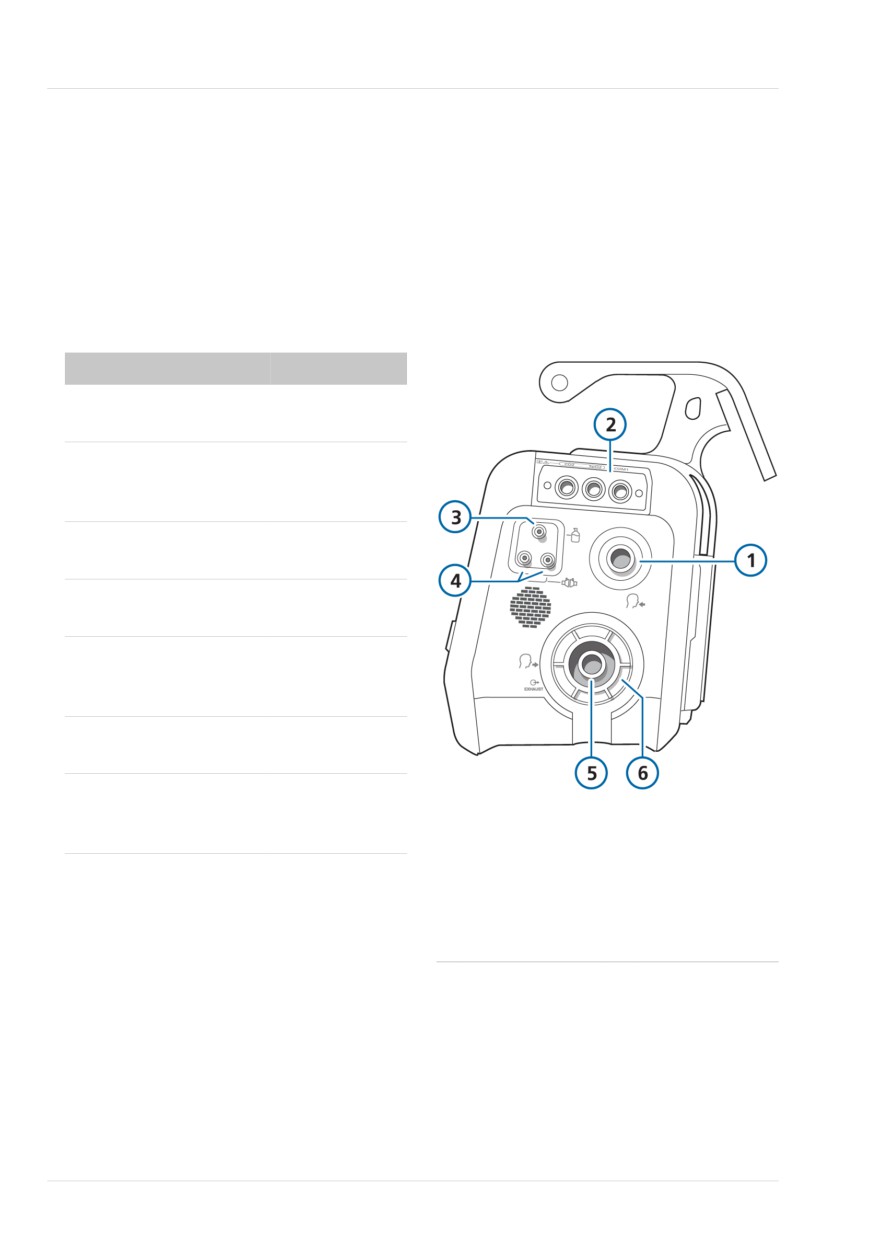
Figure 3-5 illustrates the key ports on the
Before proceeding, review the safety
ventilator for connecting the breathing cir-
information in Chapter 1.
cuit set.
Connecting the breathing circuit
For breathing circuit diagrams, see Section
comprises the following steps.
2.2.3.
For neonatal ventilation, see Chapter 6.
Figure 3-5. Key connection ports
To ...
See ...
Install the expiratory
Section 3.5.2
valve.
Select the appropriate
Section 3.5.3
breathing circuit and
components.
Assemble the breathing
Section 3.5.4
circuit.
Adjust the position of the
Section 3.5.5
breathing circuit.
Change breathing circuit
Section 3.5.6
components during venti-
lation
Connect external devices
Chapter 4
and sensors.
Perform any required
Chapter 5
tests, calibrations, and the
1
To patient inspira-
4
Flow sensor
preoperational check.
tory port
connection ports
2
Communication
5
From patient
board (optional)
expiratory port
3
Nebulizer port
6
Expiratory valve
set
70
English | 10103179/02 USA
Working with the expiratory valve set
3
3.5.2 Working with the expiratory
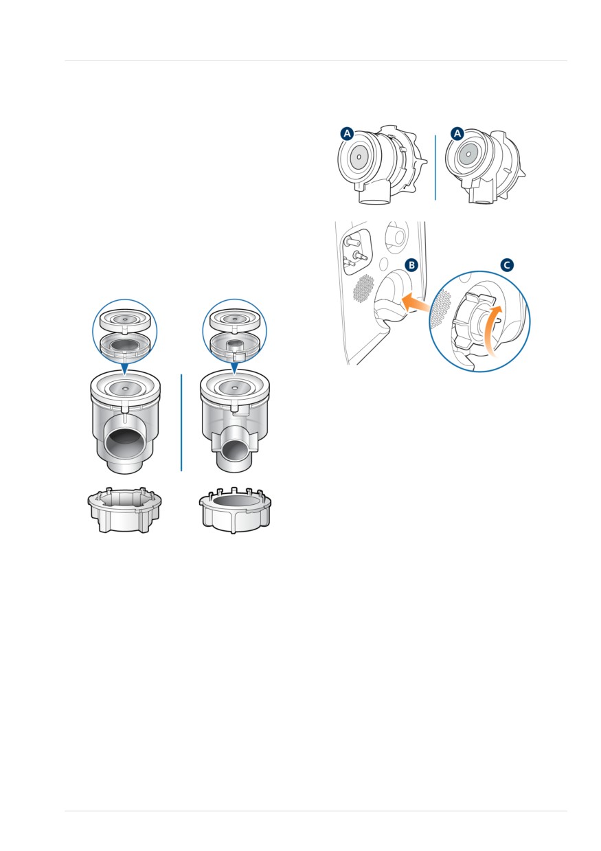
Figure 3-7. Installing the expiratory valve set
valve set
Adult/Ped
Neonatal
This section describes how to assemble/
install, and remove/disassemble the expira-
tory valve set.
Be sure to install the correct expiratory
valve for the selected patient group.
Figure 3-6. Comparison between the Adult/Ped
and Neonatal expiratory valves (differences
highlighted in blue)
Adult/Ped
Neonatal
To remove and disassemble the expiratory
valve set
1. Remove the expiratory valve set from
the expiratory port on the ventilator.
2. Holding the expiratory valve housing,
remove the silicone membrane (A in
Figure 3-7) by lifting it up.
To assemble/install the expiratory valve set
Refer to Figure 3-7.
1. Remove the safety cover.
2. Ensure the membrane is properly
aligned with the expiratory valve
housing and the metal plate faces up
(A).
3. Position the expiratory valve set in the
expiratory port (B) and twist the lock-
ing ring clockwise until it locks into
place (C).
Hamilton Medical | HAMILTON-T1 Operator's Manual
71
3 Preparing the ventilator
3.5.3 Selecting the breathing circuit
Inspiratory bacteria filter
components
To prevent patient or ventilator contamina-
tion, be sure to connect a bacteria (inspira-
Select the correct breathing circuit parts
tory) filter or HMEF between the patient
for your patient.
and the inspiratory port.
For neonatal ventilation, see Chapter 6.
For neonatal patients, use a neonatal-
Table 3-8. Breathing circuit component specifi-
pediatric HMEF.
cations
If no inspiratory filter is used, the exhaled
Patient data/
Adult
Pediatric
gas can contaminate the ventilator. If you
Component
are not using an inspiratory filter, and an
Patient height
> 130
30 to 150
exhalation obstructed alarm is generated,
(cm)
the ventilator may be contaminated. Have
the ventilator serviced.
IBW (kg)
> 30
3 to 48
Expiratory bacteria filter
Breathing circuit
15 to 22
10 to 22
limb ID (mm)21
Before using an expiratory filter with
nebulization, review the safety informa-
Flow sensor
Adult/Ped
Adult/Ped
tion in Section 1.6.5.
CO2 airway
Adult/Ped22
Adult/Ped22
An expiratory filter is not technically
adapter
required on the HAMILTON-T1. The
expiratory valve design prevents internal
ventilator components from coming into
3.5.3.1 Using a filter in the breathing cir-
contact with the patient’s exhaled gas,
cuit
preventing any cross-contamination. How-
ever, your institution’s protocol for certain
circumstances may require the use of an
NOTICE
expiratory filter (COVID-19 or other illness/
When connecting a filter to the inspira-
disease, no room contamination, and so
tory or expiratory port, pay special atten-
on).
tion to the fit and seal of the filter to the
port, in particular with filters that offer
If you use an expiratory filter, place it on
the patient side of the expiratory valve set.
additional connectors (such as a luer
connector).
Monitor closely for increased expiratory
circuit resistance.
For proper function, it is important that
all components in the breathing circuit
An Exhalation obstructed alarm may also
set are properly positioned and securely
indicate excessive expiratory circuit resis-
connected.
tance. If the Exhalation obstructed alarm
occurs repeatedly, remove the expiratory
Before proceeding, review the safety
filter immediately. If you otherwise suspect
information in Chapter 1.
21 When using coaxial breathing sets, follow the manufacturer’s recommendations for each patient group.
22 When tracheal tube ID > 4 mm.
72
English | 10103179/02 USA

Using a speaking valve in the breathing circuit
3
increased expiratory circuit resistance,
3.5.4.1 Connecting the flow sensor
remove the expiratory filter or replace the
filter to eliminate it as a potential cause.
NOTICE
Heat and moisture exchanging filter
To prevent inaccurate flow sensor read-
(HMEF)
ings, make sure the flow sensor is
correctly connected.
The HMEF is a passive humidification com-
ponent used together with a bacteria
Before proceeding, review the safety
filter. Use an HMEF when ventilating with
information in Chapter 1.
a coaxial breathing system.
To connect a flow sensor to the breathing
3.5.3.2 Using a speaking valve in the
circuit
breathing circuit
1. Insert a flow sensor into the breathing
circuit in front of the patient connec-
A speaking valve allows certain trache-
tion (Figure 3-8).
ostomized adult and pediatric patients to
communicate verbally, in addition to
See also the breathing circuit diagrams
numerous other clinical benefits.
in Section 2.2.3.
2. Attach the blue and clear tubes to the
Speaking valve compatibility is an option
flow sensor connection ports on the
available for Adult/Ped invasive ventilation
ventilator (Figure 3-5).
when using any of the following modes:
PCV+, PSIMV+, and SPONT.
The blue tube attaches to the blue
connection port. The clear tube
For setup details, see Section 4.7. For
attaches to the white connection port.
details about working with the speaking
3. Calibrate the flow sensor and perform
valve, see Section 10.8.
the Leak test. See Section 5.4.
3.5.4 Assembling the patient breath-
Figure 3-8. Connecting the flow sensor to the
Y-piece or circuit
ing circuit
Adult/Ped, flow sensor connection -
Assemble the appropriate breathing circuit
dual limb circuit, Y-piece
for your patient. Commonly used standard
breathing circuit configurations are illus-
trated in Section 2.2.3.
For neonatal ventilation, see Chapter 6.
Adult/Ped, flow sensor connection -
coaxial circuit
Neonatal, flow sensor connection -
dual limb circuit, Y-piece
Hamilton Medical | HAMILTON-T1 Operator's Manual
73
3 Preparing the ventilator
3.5.4.2 Use of adult/pediatric flow sensor
3.5.5 Positioning the breathing circuit
with neonatal/pediatric breathing circuits
NOTICE
With small pediatric patients whose IBW is
below 20 kg, using an adult/pediatric
• To prevent water accumulation in the
breathing circuit can generate too much
flow sensor and tubing, position the
dead space, resulting in ineffective ventila-
flow sensor tubing on top of the flow
tion.
sensor.
• Ensure there is no undue stress placed
For these patients, consider using a
on any tubing or cables.
neonatal/pediatric breathing circuit with
an adult/pediatric flow sensor instead.
After assembly, position the breathing cir-
To use an adult/pediatric flow sensor with
cuit so that the hoses will not be pushed,
a neonatal/pediatric breathing circuit
pulled, or kinked as a result of a patient's
movement, transport, or other activities,
1.
Verify that the Adult/Ped patient
including scanner bed operation and
group is selected.
nebulization.
2.
Verify that the patient IBW is below
20 kg.
The next step is to perform all required
tests, calibrations, and the preoperational
3.
Set up the ventilator for adult/pedi-
check. See Chapter 5.
atric ventilation with the adult/pedi-
atric flow sensor, but connect a
neonatal/pediatric breathing circuit.
3.5.6 Changing breathing circuit com-
ponents during ventilation
4.
Perform the Leak test, calibrate the
flow sensor, and perform other preop-
During ventilation, it may be necessary to
erational checks. See Section 5.4.
add components to the breathing circuit,
or to change existing components. To do
5.
Connect the patient.
so in the safest manner for the patient
6.
Start ventilation.
and personnel, we recommend following
this general process:
1. Enter Standby.
2. Provide alternative ventilation for the
patient.
3. Change or add components, in accor-
dance with your institution's standards
and protocols. See Section 1.5.1 for
important safety information.
4. Perform the preoperational check
(Section 5.4).
5. Re-connect the patient.
6. Verify settings, and resume ventila-
tion.
74
English | 10103179/02 USA
4
Setting up external devices and
sensors
4.1
Overview
76
4.2
Setting up a humidifier
76
4.3
Setting up CO2 monitoring
77
4.4
Setting up SpO2 monitoring
81
4.5
Enabling sensors
81
4.6
Setting up nebulization
82
4.7
Setting up a speaking valve
83
4.8
Connecting to external devices
85
75
4 Setting up external devices and sensors
4.1 Overview
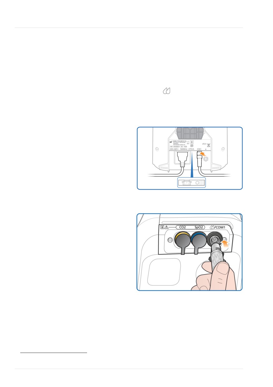
3. Plug the humidifier into primary
power.
The HAMILTON-T1 supports a variety of
4. Connect the communication cable:
external devices and sensors for ventila-
tion, including:
- Connect one end of the cable to the
humidifier (Figure 4-1).
• Humidifier
- Connect the other end of the cable
• CO2 monitoring sensors
to the
/COM1 port on the com-
• Pulse oximetry (SpO2 monitoring)
munication board (Figure 4-2).
sensors
Figure 4-1. Connect communication cable to
• Nebulizers
the humidifier
• Speaking valves
This chapter describes how to set them up
for ventilation.
4.2 Setting up a humidifier
Before proceeding, review the safety
information in Chapter 1.
When used with the optional HAMILTON-
Figure 4-2. Connect HAMILTON-H900 to the
H900 humidifier, the ventilator supports
ventilator
remote access to the humidifier controls
and status.23,24
Other humidifiers are supported, without
the integration. To connect a non-Hamil-
ton Medical humidifier, refer to the manu-
facturer's Instructions for use.
To connect the HAMILTON-H900 humidifier
to the ventilator
1. Attach the humidifier to the trolley, if
appropriate. See the Installation Guide
for HAMILTON-H900 Humidifier on
HAMILTON-C1/T1 Trolley (PN
10099119).
2. Connect a potential equalization cable
to the humidifier and to a grounding
socket at your facility.
23 Not available in all markets.
24 Supported for HAMILTON-H900 software version 1.05b and later.
76
English | 10103179/02 USA
Setting up CO2 monitoring
4
For additional details about:
4.3.1 Mainstream CO2 measurement
• Connecting the humidifier to the
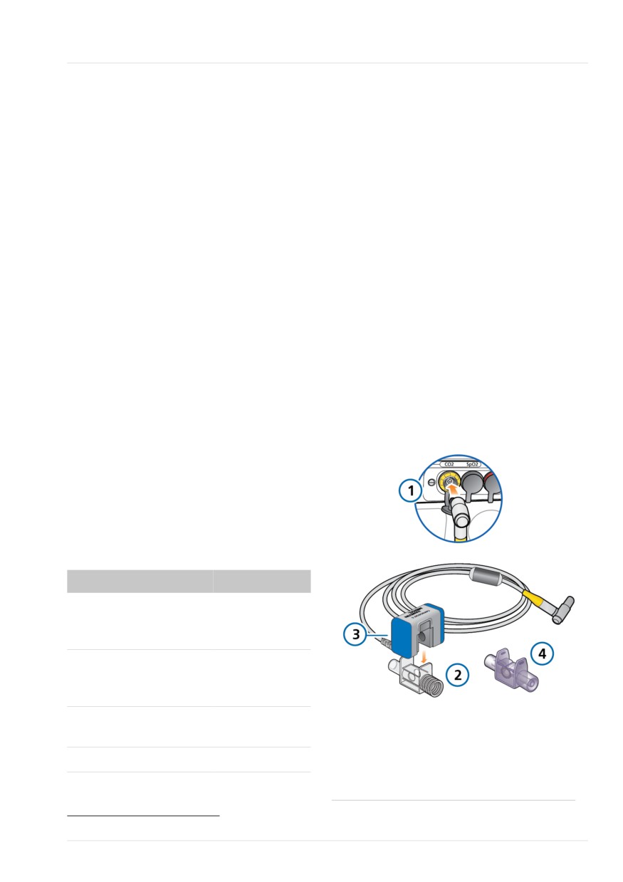
The CO2 monitoring option comprises the
breathing circuit, see Section 2.2.3.
following components (shown in Figure
4-3): communication board, airway
• Working with the humidifier, see the
adapter, and CO2 sensor.
HAMILTON-H900 Instructions for use.
• Controlling the humidifier from the
The sensor generates infrared light and
ventilator, see Chapter 11.
beams it through the airway adapter to a
detector on the opposite side. CO2 from
the patient, flowing through the main-
4.3 Setting up CO2 monitoring
stream airway adapter, absorbs some of
this infrared energy.
Before proceeding, review the safety
information in Chapter 1.
The system determines the CO2 concentra-
tion in the breathing gases by measuring
CO2 monitoring data is helpful for the
the amount of light absorbed.
assessment of the patient’s airway
integrity or ensuring proper endotracheal
The ventilator displays CO2 measurements
tube placement, among other applica-
as numeric values, waveforms, trends, and
tions.
loops.
Two CO2 measurement options are avail-
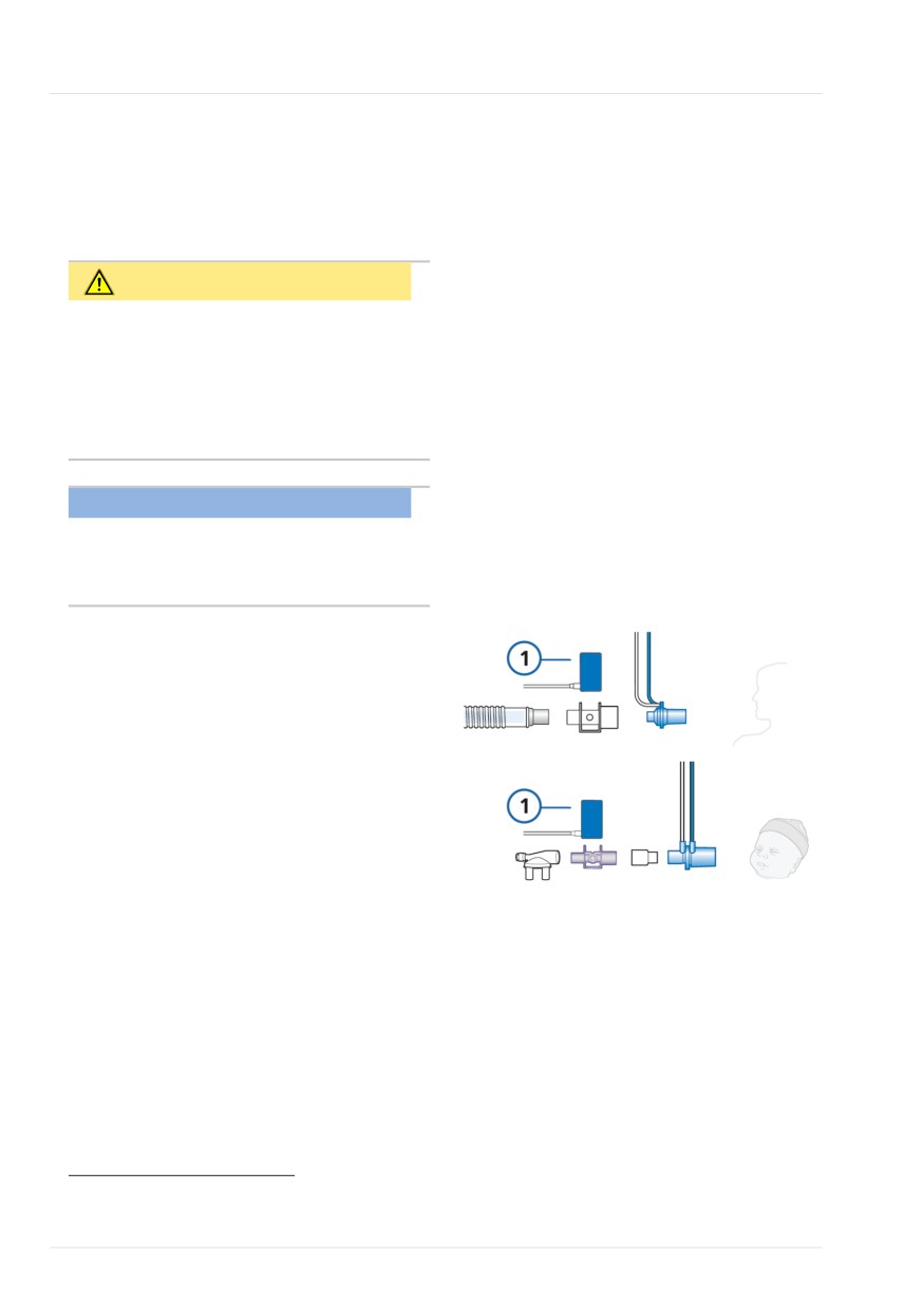
Figure 4-3. Mainstream CO2 monitoring com-
able: mainstream and sidestream. Which
ponents and assembly
option you use depends on the clinical
setting.25
Enabling CO2 measurement on the ventila-
tor requires enabling the CO2 hardware
(in Configuration) and enabling the sensor.
Table 4-1. CO2 measurement overview
For details about ...
See ...
Mainstream CO2 mea-
Section 4.3.1
surement, connection,
and use
Sidestream CO2 measure-
Section 4.3.2
ment, connection, and
use
Enabling the CO2 hard-
Section 13.11.3
1
Communication
3
CO2 sensor
ware
board with CO2
connection port
Enabling the CO2 sensor
Section 4.5
2
Airway adapter
4
Airway adapter
(Adult/Ped.)
(Neonatal)
25 The volumetric capnogram is only available when using a mainstream CO2 sensor.
Hamilton Medical | HAMILTON-T1 Operator's Manual
77
4 Setting up external devices and sensors
4.3.1.1 Connecting the mainstream CO2
4. When connecting a CO2 sensor for
sensor
the first time, perform the zero calib-
ration of the sensor/adapter, if
Before proceeding, review the safety
needed, as described in Section 5.4.5.
information in Chapter 1.
5. Connect the sensor/adapter to the
breathing circuit proximal to the
CAUTION
patient, in a vertical position. See
Figure 4-4.
When using active humidification, pre-
vent water accumulation in the CO2
Do not place the airway adapter
adapter by ensuring that it is positioned
between the ET tube and any con-
at a ≥ 45° angle relative to the floor.
nected adapter, as this may allow
Excess water can affect the sensor mea-
patient secretions to accumulate in
surements.
the adapter.27
The sensor cable should face away
from the patient.
NOTICE
6. Secure the cable safely out of the way.
You must use an appropriate adapter to
connect the mainstream CO2 sensor to a
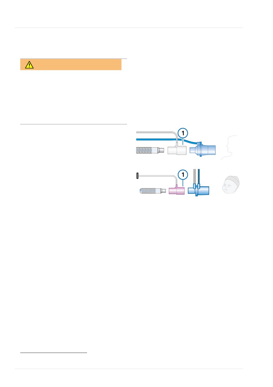
Figure 4-4. Connecting CO2 sensor/adapter (1)
neonatal flow sensor.
to breathing circuit
Adult/Ped
Ensure the CO2 sensor and adapter are
clean and dry before connection.
To set up mainstream CO2 monitoring
Refer to Figure 4-3.
1. Connect the sensor cable to the CO2
Neonatal
connection port (1) on the ventilator.
2. Attach the CO2 sensor (3) to the air-
way adapter (2), aligning the arrows
on both components.
Press the components together until
they click.
3. If needed, connect the potential
equalization USB cable to the USB
port and a grounding socket at your
facility.26
26 Recommended in all cases. Not required when the device is running on DC or battery power, or when the communication Y-cable
to HAMILTON-H900 and RS-232 is in use.
27 You can connect the CO2 sensor in front of or behind the flow sensor according to your institution’s protocol.
78
English | 10103179/02 USA
Sidestream CO2 measurement
4
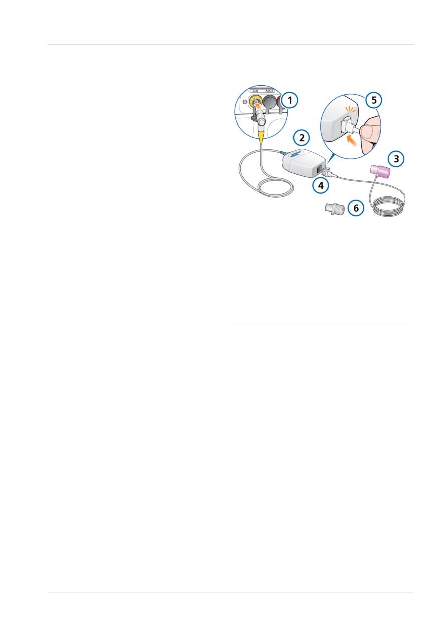
To verify the quality of the connection
Figure 4-5. Sidestream CO2 monitoring compo-
nents and assembly
4 Check the capnogram (CO2 wave-
form) on the ventilator display.
If CO2 levels are higher than
expected, check the patient condition.
If you determine that the patient’s
condition is not contributing, calibrate
the sensor (Section 5.4.5).
To disconnect the sensor cable from the
ventilator
4 Pull back on the connector sheath and
disengage from the connection port
on the ventilator.
1
Communication
4
Sampling cell
board with CO2
4.3.2 Sidestream CO2 measurement
connection port
The LoFlo CO2 module is a sidestream
2
CO2 module
5
Connecting
CO2 monitoring system comprising the
sampling cell
following components (shown in Figure
to module
4-5): communication board, airway
3
Airway adapter
6
Airway adapter
sampling adapter, and CO2 module.
(Neonatal)
(Adult/Ped.)
The module generates infrared light and
beams it through the sample cell to a
detector on the opposite side. CO2 from
the patient that is aspirated into the sam-
ple cell absorbs some of this energy. The
system uses a sampling rate of 50 ml/min.
The system determines CO2 concentration
in the breathing gases by measuring the
amount of light absorbed.
The ventilator displays CO2 measurements
as numeric values, waveforms, trends, and
loops.
Hamilton Medical | HAMILTON-T1 Operator's Manual
79
4 Setting up external devices and sensors
4.3.2.1 Connecting the sidestream CO2
5. Connect the adapter between the
sensor
inspiratory limb and the flow sensor
(or between the inspiratory limb and
HMEF, if used). See Figure 4-6.
WARNING
The sampling line should face away
Connect the CO2 airway adapter accord-
from the patient.
ing to your institution’s policy and proce-
6. Secure the sampling line safely out of
dures. Connecting the airway adapter
the way.
between the flow sensor and the endo-
tracheal tube increases dead space and
Figure 4-6. Connecting CO2 adapter (1) to the
may contribute to incorrect volume mea-
breathing circuit
surements.
Adult/Ped
Before proceeding, review the safety
information in Chapter 1.
To set up CO2 sidestream monitoring
Refer to Figure 4-5.
Neonatal
1. Connect the CO2 module cable to the
CO2 connection port (1) on the ventila-
tor.
2. Insert the sample cell (4) into the CO2
module (2). The sample cell clicks into
place.
To remove the sample cell
Inserting the sample cell into the
1. Remove the airway adapter from the
module automatically starts the
breathing circuit.
sampling pump. Removing the cell
turns the pump off.
2. Press down on the locking tab and
remove the sample cell from the CO2
3. If needed, connect the potential
module.
equalization USB cable to the USB
port and a grounding socket at your
facility.28
4. Perform the zero calibration of the
adapter, if necessary, as described in
Section 5.4.5 before connecting it to
the breathing circuit.
28 Recommended in all cases. Not required when the device is running on DC or battery power, or when the communication Y-cable
to HAMILTON-H900 and RS-232 is in use.
80
English | 10103179/02 USA
Setting up SpO2 monitoring
4
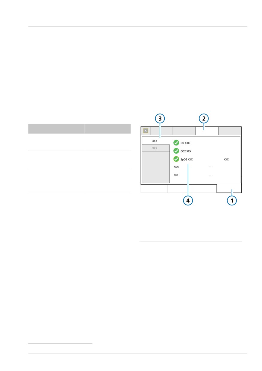
To enable sensor monitoring
4.4 Setting up SpO2 monitoring
1. Touch System > Sensors > On/Off.
The HAMILTON-T1 supports input of SpO2
2. Select the appropriate checkboxes
and related pulse oximetry data, and pro-
(O2 sensor, CO2 sensor, SpO2 sensor)
vides integrated monitoring and data
to enable/disable the monitoring func-
display.
tions, as desired.
Enabling SpO2 measurement on the venti-
The ventilator always enables O2 monitor-
lator requires enabling the SpO2 hardware
ing upon restart.
(in Configuration) and enabling the SpO2
sensor.
Figure 4-7. System > Sensors > On/Off window
Table 4-2. SpO2 measurement overview
For details about ...
See ...
Activating the SpO2
Section 13.11.3
hardware
Enabling the SpO2
Section 4.5
sensor
Working with SpO2
Pulse Oximetry
data
Instructions for
Use
4.5 Enabling sensors
1
System
3
On/Off
Before proceeding, review the safety
2
Sensors
4
O2 sensor,
information in Chapter 1.
CO2 sensor29,
In addition to hardware activation for CO2
SpO2 sensor29
and SpO2 measurement (Section 13.11.3),
the O2, CO2, and/or SpO2 sensors must
be individually enabled for monitoring
data to be available.
29 If the option is installed and activated.
Hamilton Medical | HAMILTON-T1 Operator's Manual
81
4 Setting up external devices and sensors
To connect an Aerogen nebulizer to the
4.6 Setting up nebulization
breathing circuit set
The HAMILTON-T1 supports the use of
1. Connect the nebulizer to the breath-
Aerogen and pneumatic nebulizers for
ing circuit as appropriate. See Figure
adult and pediatric patients.30
4-9.
For neonatal patients, use an Aerogen
2. Connect the nebulizer USB cable to
nebulizer system31; the use of pneumatic
the ventilator USB port.
nebulizers is not supported. For Aerogen
For nebulizer details and operation, see
connection and device details, refer to the
Section 10.7.
manufacturer's Instructions for use.
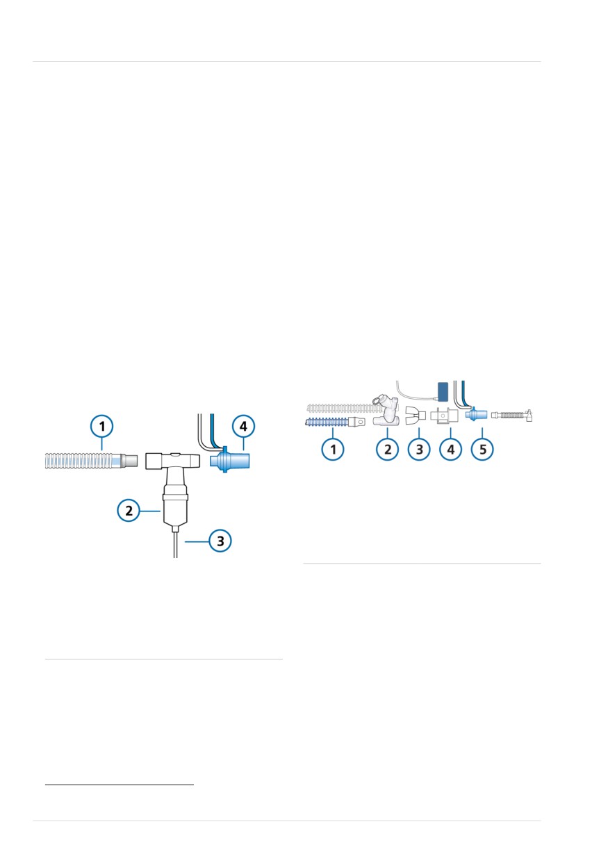
The following figure presents a nebulizer
To connect a pneumatic nebulizer to the
placement example. For other placement
breathing circuit set
options, see the Nebulizer positioning
1. Connect the nebulizer to the breath-
guidelines (ELO2020-124-TW), available
ing circuit as shown in Figure 4-8.
online on MyHamilton, and the manufac-
2. Connect the nebulizer tubing to the
turer's Instructions for use.
Nebulizer port on the ventilator (Figure
Figure 4-9. Connecting an Aerogen nebulizer
2-4).
Figure 4-8. Connecting a pneumatic nebulizer
1
Inspiratory limb
4
CO2 adapter/
sensor (optional)
2
Aerogen nebuli-
5
Flow sensor
zer
3
Y-piece
1
Breathing circuit
3
Nebulizer tubing
(coaxial shown)
to ventilator
2
Nebulizer
4
Flow sensor
For additional details, refer to the manufac-
turer's Instructions for use.
30 See the Hamilton Medical e-catalog for compatible devices.
31 Aerogen nebulization is not supported for patients younger than 28 days old in the USA.
82
English | 10103179/02 USA
Setting up a speaking valve
4
4.7 Setting up a speaking valve
4.7.1 Activating speaking valve
compatibility
A speaking valve allows certain trache-
ostomized adult and pediatric patients to
NOTICE
communicate verbally, in addition to
numerous other clinical benefits.
If PEEP > 0, auto-triggering can occur
while using a speaking valve.
Table 4-3 describes the steps required to
set up the patient for ventilation with a
By default, speaking valve compatibility is
speaking valve.
deactivated (OFF).
Table 4-3. Speaking valve patient setup
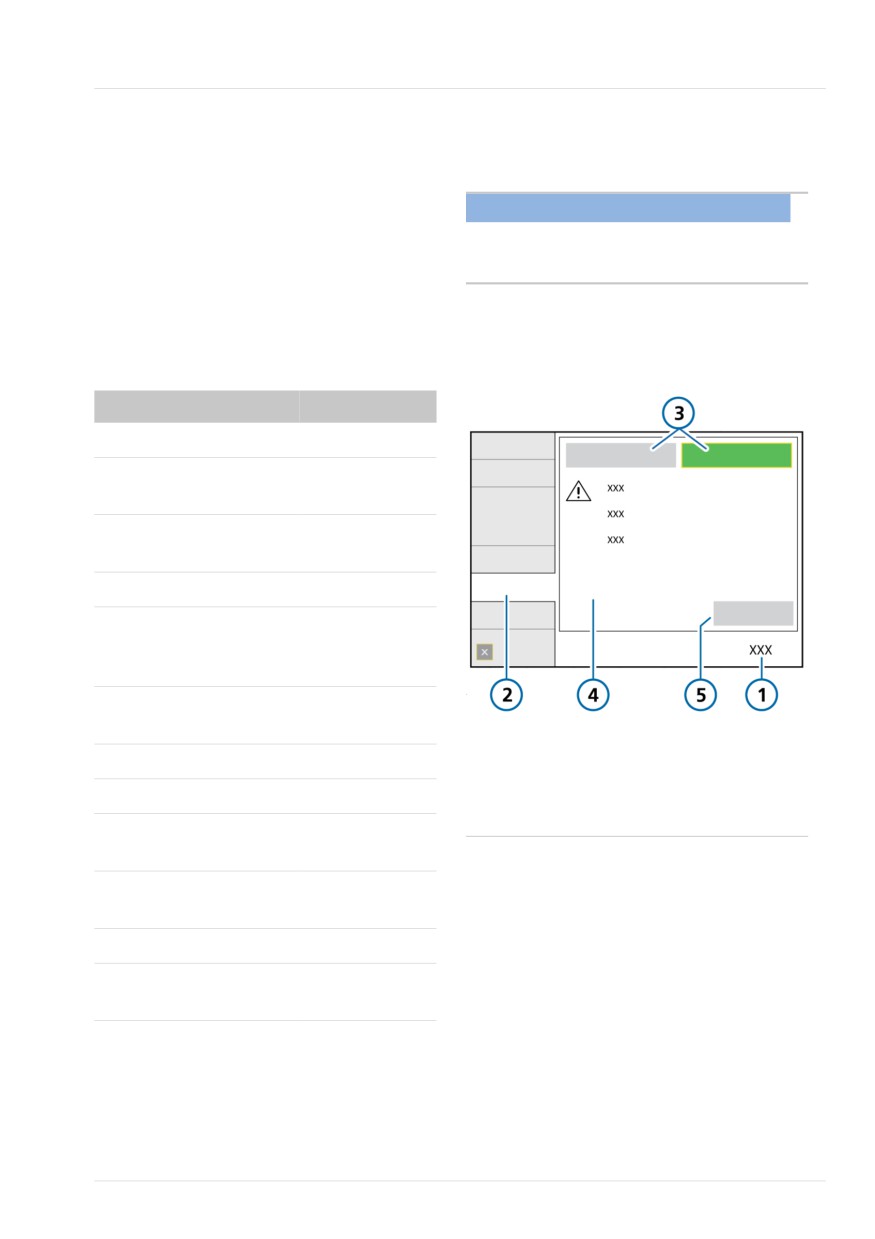
Figure 4-10. Controls > SpeakValve window
To ...
See ...
Connect the speaking valve
Select a compatible
Section 10.8
mode.
Activate speaking valve
Section 4.7.1
compatibility.
Deflate the tracheostomy cuff.
Connect the speaking
Section 4.7.2
valve to the breathing cir-
cuit set and patient.
Review control settings
Section 10.8.4
and alarm limits.
and Chapter 5
1
Controls
4
Important safety
Start ventilation.
information
2
SpeakValve
5
Apply
Remove the speaking valve
3
SpeakValve ON, SpeakValve OFF
Remove speaking valve from the breathing
circuit.
Deactivate speaking valve Section 4.7.3
compatibility.
Inflate the tracheostomy cuff.
Review control settings
Section 10.8.4
and alarm limits.
and Chapter 5
Hamilton Medical | HAMILTON-T1 Operator's Manual
83
4 Setting up external devices and sensors
To activate the use of a speaking valve
4.7.3 Deactivating speaking valve
with the ventilator
compatibility
1. Touch Controls > SpeakValve.
In some cases, compatibility is automati-
Be sure to carefully read the safety
cally deactivated. See Section 10.8.1.
information displayed in the window.
2. Be sure to do the following:
To deactivate speaking valve compatibility
- Deflate the cuff.
1. Touch Controls > SpeakValve.
- Connect a speaking valve.
2. Touch SpeakValve OFF, then touch
Apply.
3. To activate compatibility, touch Speak-
Valve ON, then touch Apply.
3. Be sure to do the following:
Consider setting PEEP to 0 while
- Remove the speaking valve from the
compatibility is activated.
breathing circuit.
As long as compatibility is activated, the
- Inflate the cuff.
message SpeakValve ON is active and the
When compatibility is deactivated (OFF),
following safety messages are shown in
the following safety messages are shown
the SpeakValve window:
in the SpeakValve window:
Messages in SpeakValve window
Messages in SpeakValve window
The tracheostomy cuff must be com-
Remove the speaking valve, deactivate
pletely deflated prior to connecting a
speaking valve compatibility, and
speaking valve.
inflate the tracheostomy cuff.
Disconnection alarms and the Inspira-
All alarms are enabled. The Vt alarms
tory limitation alarm are disabled. The
are based on VTE.
Vt alarms are based on VTI. The
Apnea backup ventilation is enabled.
ExpMinVol alarm limits are set to OFF.
Apnea backup ventilation is disabled.
Upon deactivation, alarms and monitoring
parameters return to their previous opera-
4.7.2 Connecting a speaking valve to
tion, and the ExpMinVol alarm limits are
the breathing circuit set
reset based on the patient's IBW.
Connect the speaking valve between the
For details, see Sections 10.8.3 and
flow sensor and the patient interface.
10.8.4.
Pay careful attention to any safety
information and requirements for cuff
deflation.
For connection details, refer to the speak-
ing valve manufacturer's Instructions for
use.
84
English | 10103179/02 USA
Connecting to external devices
4
4.8 Connecting to external
devices
You can connect the ventilator to a
patient monitor, a Patient Data Manage-
ment System (PDMS), or computer using
the communication port on the communi-
cation board, if installed. For details, see
the Communication Interface User Guide,
available on MyHamilton.
When used with the Hamilton Connect
App, medical caregivers can view ventila-
tion-related information directly on a
smartphone.32
For additional information see:
• For a list of supported smartphones,
see MyHamilton.
• For details about selecting a communi-
cation protocol for use with the com-
munication board, see Section 13.3.3.
• For details about enabling a supported
connection type, such as Bluetooth
wireless technology or Wireless LAN
(Wi-Fi) on the ventilator, see Section
11.2.
• For details about configuring connectiv-
ity settings, including Connectivity con-
figuration file import/export and Hamil-
ton Connect Module firmware update,
see Section 13.9.
• For details about the Hamilton Connect
App, see the Hamilton Connect App
Instructions for use.
32 Not available in all markets.
Hamilton Medical | HAMILTON-T1 Operator's Manual
85
4 Setting up external devices and sensors
86
English | 10103179/02 USA
5
Specifying ventilation settings
5.1
Process overview
88
5.2
Selecting the patient group
88
5.3
Entering patient data
90
5.4
Performing the preoperational check, tests, and calibrations
90
5.5
Selecting the ventilation mode
98
5.6
Reviewing and adjusting ventilation settings
99
5.7
Setting alarm limits
103
5.8
Starting ventilation
108
5.9
Stopping ventilation (Standby)
108
5.10
About the control parameters
109
87
5 Specifying ventilation settings
5.1 Process overview
5.2 Selecting the patient group
This section explains how to set up the
Before proceeding, review the safety
HAMILTON-T1 for ventilation on an indi-
information in Chapter 1.
vidual patient.
The HAMILTON-T1 supports the following
Setting up ventilation generally comprises
patient groups: Adult/Ped (adult and pedi-
the following steps, each of which is
atric patients) and Neonatal.
described in this chapter:
Table 5-1. Patient groups
•
Selecting the patient group
•
Selecting the desired preconfigured
Adult/Ped
Neonatal
settings (Quick setup)
Sex: Male, Female
Weight: 0.2 to 30 kg
•
Specifying patient data
Height: 30 to 250 cm
Minimum delivered
tidal volume:
2 ml
•
Performing the preoperational check,
IBW: 3 to 139 kg
including:
Minimum delivered
- Performing a breathing circuit Leak
tidal volume:
20 ml
test
- Calibrating the flow sensor, O2
To select the patient group and initial
sensor, and zero calibration of the
settings
CO2 sensor
1. In the Standby window (Figure 5-1),
- Calibrating the breathing circuit
touch the desired patient group tab:
(nCPAP and nCPAP-PC modes)
- Adult/Ped
•
Testing alarms
- Neonatal
•
Selecting the ventilation mode
- Last patient. Reuse the last active
ventilator parameters.
•
Reviewing and adjusting control
The icon for the selected patient
settings
group appears to the left of the mode
•
Reviewing and adjusting alarm limits
name at the top left of the display
(Figure 2-6).
2. For a new patient, touch the desired
Quick setup button (Section 5.2.1).
The settings saved with the selected Quick
setup are loaded and displayed, in addi-
tion to the default patient sex/height/IBW
(Adult/Ped) or weight (Neonatal).
88
English | 10103179/02 USA
About Quick setups: preconfigured settings
5
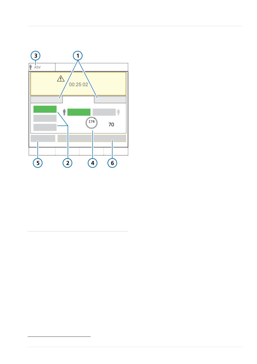
Figure 5-1. Patient group options in Standby
5.2.1 About Quick setups: preconfi-
window
gured settings
For each of the patient groups, you can
define up to three different default config-
urations, referred to as Quick setups.
During patient setup, you can then quickly
preconfigure the ventilator per your stan-
dard protocols, and modify settings as
needed.
Each Quick setup defines:
• A ventilation mode
• Mode control settings
• Graphic display selections
• Alarm limit settings
• Vent Status panel settings
• Vt/IBW (Adult/Ped) or Vt/kg (Neonatal)
1
Patient group
4
Sex/height/IBW
tabs
(or Weight for
• Specified humidifier settings (if con-
Neonatal) for
nected)
selected Quick
• Default CPR ventilation settings
setup
2
Quick setups
5
Preop check
The Quick setups are defined in Configura-
33
tion (Chapter 13).
3
Selected mode
6
Start ventilation
and patient group
33 When HiFlowO2 is selected: Start therapy; when CPR ventilation is on: Start CPR.
Hamilton Medical | HAMILTON-T1 Operator's Manual
89