Q2V Driving Quality. Technical Manual (Item code: Q2V-Axxxx-xxx, 2020) - page 14
12.4 d: REFERENCE
■ d1-03: Reference 3
No.
Default
Name
Description
(Hex.)
(Range)
d1-03
Reference 3
V/f
OLV OLV/PM AOLV/PM EZOLV
0.00 Hz
(0282)
Sets the frequency reference in the units from o1-03 [FrqDisplay Unit Selection].
(0.00 - 590.00 Hz)
RUN
Note:
• The upper limit value changes when the E1-04 [Max Output Frequency] and d2-01 [FRef Upper Limit] values change.
• When A1-02 = 6 [Control Method = PM AOLVector], the default setting is o1-03 = 1 [0.01% (100%=E1-04)].
• To set d1-03 to Multi-Step Speed 3, set H3-02 and H3-10 ≠ 3 [MFAI Function Select ≠ AuxFreqRef2].
■ d1-04: Reference 4
No.
Default
Name
Description
(Hex.)
(Range)
d1-04
Reference 4
V/f
OLV OLV/PM AOLV/PM EZOLV
0.00 Hz
(0283)
Sets the frequency reference in the units from o1-03 [FrqDisplay Unit Selection].
(0.00 - 590.00 Hz)
RUN
Note:
• The upper limit value changes when the E1-04 [Max Output Frequency] and d2-01 [FRef Upper Limit] values change.
• When A1-02 = 6 [Control Method = PM AOLVector], the drive sets o1-03 = 1 [0.01% (100%=E1-04)].
• This parameter sets the frequency reference of Multi-Step Speed 4.
■ d1-05: Reference 5
No.
Default
Name
Description
(Hex.)
(Range)
d1-05
Reference 5
V/f
OLV OLV/PM AOLV/PM EZOLV
0.00 Hz
(0284)
Sets the frequency reference in the units from o1-03 [FrqDisplay Unit Selection].
(0.00 - 590.00 Hz)
RUN
Note:
• The upper limit value changes when the E1-04 [Max Output Frequency] and d2-01 [FRef Upper Limit] values change.
• When A1-02 = 6 [Control Method = PM AOLVector], the drive sets o1-03 = 1 [0.01% (100%=E1-04)].
• This parameter sets the frequency reference of Multi-Step Speed 5.
■ d1-06: Reference 6
No.
Default
Name
Description
(Hex.)
(Range)
d1-06
Reference 6
V/f
OLV OLV/PM AOLV/PM EZOLV
0.00 Hz
(0285)
Sets the frequency reference in the units from o1-03 [FrqDisplay Unit Selection].
(0.00 - 590.00 Hz)
RUN
Note:
• The upper limit value changes when the E1-04 [Max Output Frequency] and d2-01 [FRef Upper Limit] values change.
• When A1-02 = 6 [Control Method = PM AOLVector], the drive sets o1-03 = 1 [0.01% (100%=E1-04)].
• This parameter sets the frequency reference of Multi-Step Speed 6.
■ d1-07: Reference 7
No.
Default
Name
Description
(Hex.)
(Range)
d1-07
Reference 7
V/f
OLV OLV/PM AOLV/PM EZOLV
0.00 Hz
(0286)
Sets the frequency reference in the units from o1-03 [FrqDisplay Unit Selection].
(0.00 - 590.00 Hz)
RUN
Note:
• The upper limit value changes when the E1-04 [Max Output Frequency] and d2-01 [FRef Upper Limit] values change.
• When A1-02 = 6 [Control Method = PM AOLVector], the drive sets o1-03 = 1 [0.01% (100%=E1-04)].
• This parameter sets the frequency reference of Multi-Step Speed 7.
12
511
12.4 d: REFERENCE
■ d1-08: Reference 8
No.
Default
Name
Description
(Hex.)
(Range)
d1-08
Reference 8
V/f
OLV OLV/PM AOLV/PM EZOLV
0.00 Hz
(0287)
Sets the frequency reference in the units from o1-03 [FrqDisplay Unit Selection].
(0.00 - 590.00 Hz)
RUN
Note:
• The upper limit value changes when the E1-04 [Max Output Frequency] and d2-01 [FRef Upper Limit] values change.
• When A1-02 = 6 [Control Method = PM AOLVector], the drive sets o1-03 = 1 [0.01% (100%=E1-04)].
• This parameter sets the frequency reference of Multi-Step Speed 8.
■ d1-09: Reference 9
No.
Default
Name
Description
(Hex.)
(Range)
d1-09
Reference 9
V/f
OLV OLV/PM AOLV/PM EZOLV
0.00 Hz
(0288)
Sets the frequency reference in the units from o1-03 [FrqDisplay Unit Selection].
(0.00 - 590.00 Hz)
RUN
Note:
• The upper limit value changes when the E1-04 [Max Output Frequency] and d2-01 [FRef Upper Limit] values change.
• When A1-02 = 6 [Control Method = PM AOLVector], the drive sets o1-03 = 1 [0.01% (100%=E1-04)].
• This parameter sets the frequency reference of Multi-Step Speed 9.
■ d1-10: Reference 10
No.
Default
Name
Description
(Hex.)
(Range)
d1-10
Reference 10
V/f
OLV OLV/PM AOLV/PM EZOLV
0.00 Hz
(028B)
Sets the frequency reference in the units from o1-03 [FrqDisplay Unit Selection].
(0.00 - 590.00 Hz)
RUN
Note:
• The upper limit value changes when the E1-04 [Max Output Frequency] and d2-01 [FRef Upper Limit] values change.
• When A1-02 = 6 [Control Method = PM AOLVector], the drive sets o1-03 = 1 [0.01% (100%=E1-04)].
• This parameter sets the frequency reference of Multi-Step Speed 10.
■ d1-11: Reference 11
No.
Default
Name
Description
(Hex.)
(Range)
d1-11
Reference 11
V/f
OLV OLV/PM AOLV/PM EZOLV
0.00 Hz
(028C)
Sets the frequency reference in the units from o1-03 [FrqDisplay Unit Selection].
(0.00 - 590.00 Hz)
RUN
Note:
• The upper limit value changes when the E1-04 [Max Output Frequency] and d2-01 [FRef Upper Limit] values change.
• When A1-02 = 6 [Control Method = PM AOLVector], the drive sets o1-03 = 1 [0.01% (100%=E1-04)].
• This parameter sets the frequency reference of Multi-Step Speed 11.
■ d1-12: Reference 12
No.
Default
Name
Description
(Hex.)
(Range)
d1-12
Reference 12
V/f
OLV OLV/PM AOLV/PM EZOLV
0.00 Hz
(028D)
Sets the frequency reference in the units from o1-03 [FrqDisplay Unit Selection].
(0.00 - 590.00 Hz)
RUN
Note:
• The upper limit value changes when the E1-04 [Max Output Frequency] and d2-01 [FRef Upper Limit] values change.
• When A1-02 = 6 [Control Method = PM AOLVector], the drive sets o1-03 = 1 [0.01% (100%=E1-04)].
• This parameter sets the frequency reference of Multi-Step Speed 12.
512
12.4 d: REFERENCE
■ d1-13: Reference 13
No.
Default
Name
Description
(Hex.)
(Range)
d1-13
Reference 13
V/f
OLV OLV/PM AOLV/PM EZOLV
0.00 Hz
(028E)
Sets the frequency reference in the units from o1-03 [FrqDisplay Unit Selection].
(0.00 - 590.00 Hz)
RUN
Note:
• The upper limit value changes when the E1-04 [Max Output Frequency] and d2-01 [FRef Upper Limit] values change.
• When A1-02 = 6 [Control Method = PM AOLVector], the drive sets o1-03 = 1 [0.01% (100%=E1-04)].
• This parameter sets the frequency reference of Multi-Step Speed 13.
■ d1-14: Reference 14
No.
Default
Name
Description
(Hex.)
(Range)
d1-14
Reference 14
V/f
OLV OLV/PM AOLV/PM EZOLV
0.00 Hz
(028F)
Sets the frequency reference in the units from o1-03 [FrqDisplay Unit Selection].
(0.00 - 590.00 Hz)
RUN
Note:
• The upper limit value changes when the E1-04 [Max Output Frequency] and d2-01 [FRef Upper Limit] values change.
• When A1-02 = 6 [Control Method = PM AOLVector], the drive sets o1-03 = 1 [0.01% (100%=E1-04)].
• This parameter sets the frequency reference of Multi-Step Speed 14.
■ d1-15: Reference 15
No.
Default
Name
Description
(Hex.)
(Range)
d1-15
Reference 15
V/f
OLV OLV/PM AOLV/PM EZOLV
0.00 Hz
(0290)
Sets the frequency reference in the units from o1-03 [FrqDisplay Unit Selection].
(0.00 - 590.00 Hz)
RUN
Note:
• The upper limit value changes when the E1-04 [Max Output Frequency] and d2-01 [FRef Upper Limit] values change.
• When A1-02 = 6 [Control Method = PM AOLVector], the drive sets o1-03 = 1 [0.01% (100%=E1-04)].
• This parameter sets the frequency reference of Multi-Step Speed 15.
■ d1-16: Reference 16
No.
Default
Name
Description
(Hex.)
(Range)
d1-16
Reference 16
V/f
OLV OLV/PM AOLV/PM EZOLV
0.00 Hz
(0291)
Sets the frequency reference in the units from o1-03 [FrqDisplay Unit Selection].
(0.00 - 590.00 Hz)
RUN
Note:
• The upper limit value changes when the E1-04 [Max Output Frequency] and d2-01 [FRef Upper Limit] values change.
• When A1-02 = 6 [Control Method = PM AOLVector], the drive sets o1-03 = 1 [0.01% (100%=E1-04)].
• This parameter sets the frequency reference of Multi-Step Speed 16.
■ d1-17: Jog Reference
No.
Default
Name
Description
(Hex.)
(Range)
d1-17
Jog Reference
V/f
OLV OLV/PM AOLV/PM EZOLV
6.00 Hz
(0292)
Sets the Jog frequency reference in the units from o1-03 [FrqDisplay Unit Selection]. Set H1-xx
(0.00 - 590.00 Hz)
= 6 [MFDI Function Select = Jog Reference] to use the Jog frequency reference.
RUN
Note:
• The upper limit value changes when the E1-04 [Max Output Frequency] and d2-01 [FRef Upper Limit] values change.
• When A1-02 = 6 [Control Method = PM AOLVector], the drive sets o1-03 = 1 [0.01% (100%=E1-04)].
12
513
12.4 d: REFERENCE
◆ d2: REFERENCE LIMITS
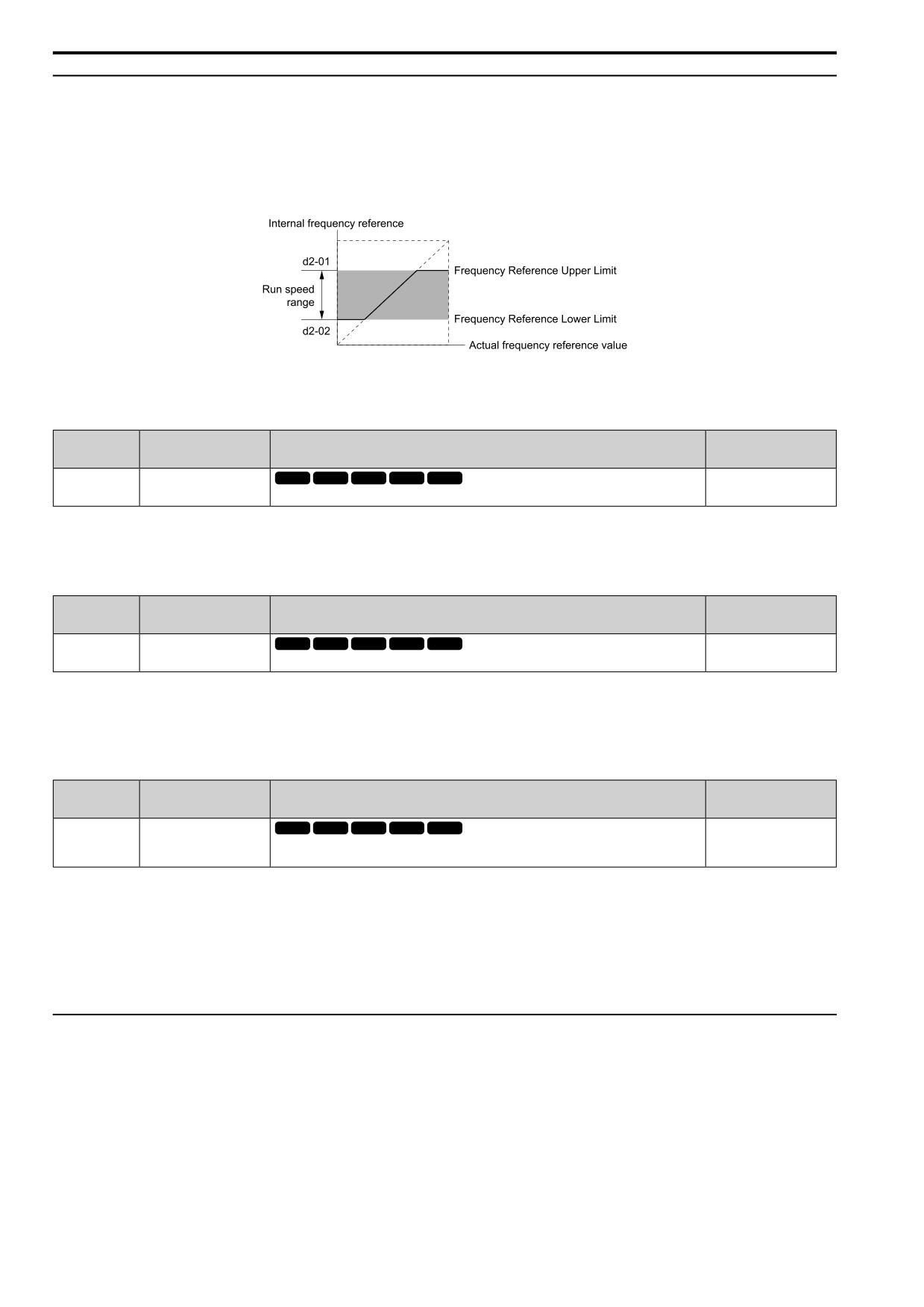
d2 parameters set the upper and lower frequency limits to control the motor speed. Apply these parameters to for
example, run the motor at low-speed due to mechanical strength concerns, or if the motor should not be run at low
speed because of lubrication issues with the gears and bearings.
The upper frequency limit is set in d2-01 [FRef Upper Limit] and the lower limit is set in d2-02 [FRef Lower
Limit].
Figure 12.50 Upper and Lower Frequency Limits
■ d2-01: FRef Upper Limit
No.
Default
Name
Description
(Hex.)
(Range)
V/f
OLV OLV/PM AOLV/PM EZOLV
d2-01
FRef Upper Limit
100.0%
(0289)
Sets maximum limit for all frequency references. The maximum output frequency is 100%.
(0.0
- 110.0%)
When the frequency reference is more than the value set in d2-01 the drive will continue to operate at the value set
in d2-01.
■ d2-02: FRef Lower Limit
No.
Default
Name
Description
(Hex.)
(Range)
d2-02
FRef Lower Limit
V/f
OLV OLV/PM AOLV/PM EZOLV
0.0%
(028A)
Sets minimum limit for all frequency references. The maximum output frequency is 100%.
(0.0
- 110.0%)
When the frequency reference is less than the value set in d2-02, the drive will continue to operate at the value set
in d2-02. The motor will accelerate to the d2-02 value after the drive receives a Run command and a lower
frequency reference than d2-02 has been entered.
■ d2-03: Analog FRef Lower Limit
No.
Default
Name
Description
(Hex.)
(Range)
d2-03
Analog FRef Lower Limit
V/f
OLV OLV/PM AOLV/PM EZOLV
0.0%
(0293)
Sets the lower limit for the master frequency reference (the first frequency of the multi-step speed
(0.0
- 110.0%)
reference) as a percentage. The maximum output frequency is 100%.
This parameter does not change the lower limit of Jog reference, frequency reference for multi-step speed
operation, or the auxiliary frequency reference.
The drive operates at the value set in d2-03 when the frequency reference decreases to less than the value set in
d2-03.
Note:
When lower limits are set to parameters d2-02 [FRef Lower Limit] and d2-03, the drive uses the larger value as the lower limit.
◆ d3: JUMP FREQUENCY
The Jump frequency is a function that sets the dead band to a specified frequency band. If a machine that operated
at constant speed is operated with variable speed, it can make resonance. To operate the machine without
resonance from the natural frequency of the machinery mechanical system, use a frequency band jump.
You can program the drive to have three different Jump frequencies. Set d3-01 to d3-03 [Jump Frequency 1 to
Jump Frequency 3] to the median value for the jumped frequency and set d3-04 [Jump Frequency Width] to the
Jump frequency width.
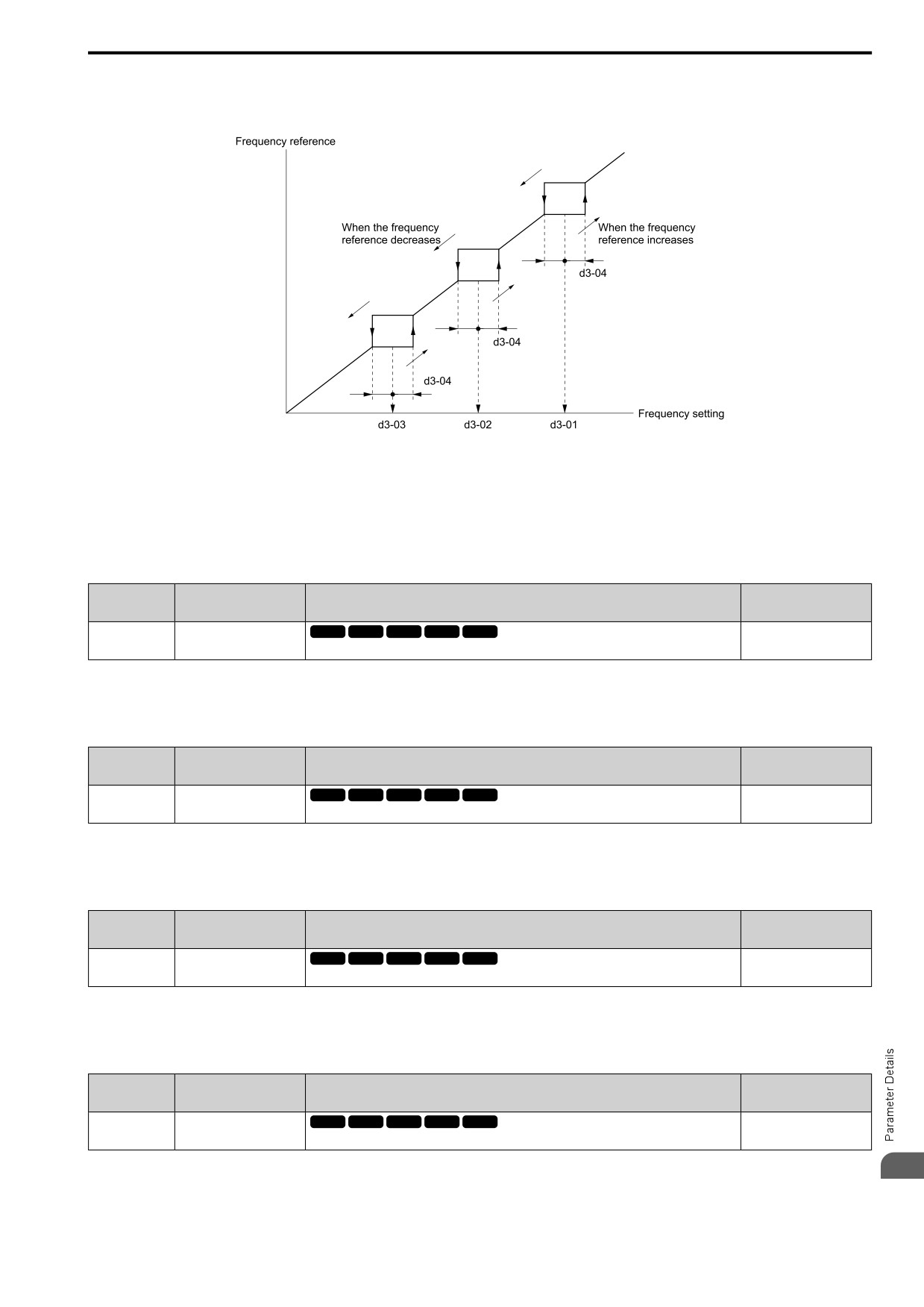
When you input a frequency reference that is the same as or near the Jump frequency width, the frequency
reference changes automatically.
514
12.4 d: REFERENCE
The drive accelerates or decelerates the motor smoothly until the frequency reference is not in the range of the
Jump frequency band. The drive will use the active accel/decel time to go through the specified dead band range.
If the frequency reference is not in the range of the Jump frequency band, switch to constant speed operation.
Figure 12.51 Jump Frequency
Note:
• When you set Jump Frequencies 1 to 3, make sure that the parameters do not overlap.
• When the drive is in the range of the Jump frequency, the frequency reference changes automatically. When Jump is executed, the
output frequency changes smoothly as specified by the values set in C1-01 [Accel Time 1] and C1-02 [Decel Time 1].
■ d3-01: Jump Frequency 1
No.
Default
Name
Description
(Hex.)
(Range)
d3-01
Jump Frequency 1
V/f
OLV OLV/PM AOLV/PM EZOLV
0.0 Hz
(0294)
Sets the median value of the frequency band that the drive will avoid.
(Determined by A1-02)
Note:
Set this parameter to 0.0 Hz to disable the Jump frequency.
■ d3-02: Jump Frequency 2
No.
Default
Name
Description
(Hex.)
(Range)
V/f
OLV OLV/PM AOLV/PM EZOLV
d3-02
Jump Frequency 2
0.0 Hz
(0295)
Sets the median value of the frequency band that the drive will avoid.
(Determined by A1-02)
Note:
Set this parameter to 0.0 Hz to disable the Jump frequency.
■ d3-03: Jump Frequency 3
No.
Default
Name
Description
(Hex.)
(Range)
d3-03
Jump Frequency 3
V/f
OLV OLV/PM AOLV/PM EZOLV
0.0 Hz
(0296)
Sets the median value of the frequency band that the drive will avoid.
(Determined by A1-02)
Note:
Set this parameter to 0.0 Hz to disable the Jump frequency.
■ d3-04: Jump Frequency Width
No.
Default
Name
Description
(Hex.)
(Range)
d3-04
Jump Frequency Width
V/f
OLV OLV/PM AOLV/PM EZOLV
1.0 Hz
(0297)
Sets the width of the frequency band that the drive will avoid.
(Determined by A1-02)
12
515
12.4 d: REFERENCE
◆ d4: FREQUENCY UP/DOWN
The d4 parameters set the Frequency Reference Hold function and Up/Down and Up/Down 2 commands.
WARNING! Sudden Movement Hazard. When you use the drive in a lifting application, you must also install external safety
circuitry. The drive does not have protection against accidental load drops in lifting applications. Install electrical and/or
mechanical safety circuit mechanisms that are isolated from the drive circuitry. If you do not use external safety circuitry, the
drive could drop the load and cause serious injury or death.
WARNING! Sudden Movement Hazard. When you use a mechanical holding brake with the drive in a lifting application, you
must close the brake if an input terminal triggers the Baseblock command to stop drive output. If you enter the baseblock
command, the motor will suddenly coast and the load will slip, which can cause serious injury or death.
• Frequency Reference Hold Function Command: This acceleration/deceleration ramp hold command uses an
MFDI to momentarily stop the acceleration/deceleration of the motor, and continues to operate the motor at the
output frequency at which the command reference was input. Turn OFF the acceleration/deceleration ramp hold
command to continue acceleration/deceleration.
With a crane for example, use the function and a 2-stage push button to stop acceleration and operate at low
speed with one of the output frequencies.
• Up/Down command: The Up/Down command is a function to activate and deactivate an MFDI to increase and
decrease the frequency reference. The Up/Down command overrides frequency references from the analog input
terminal, pulse train input terminal, and keypad.
• Up/Down 2 command: The Up/Down 2 command is a function that adds a set bias value to the frequency
reference to accelerate or decelerate. The Up/Down 2 command activates and deactivates the MFDI to add a
bias value.
■ d4-01: FRef Hold Selection
No.
Default
Name
Description
(Hex.)
(Range)
V/f
OLV OLV/PM AOLV/PM EZOLV
d4-01
FRef Hold Selection
0
(0298)
Sets the function that saves the frequency reference or the frequency bias (Up/Down 2) after a
(0, 1)
Stop command or when de-energizing the drive.
Set H1-xx [MFDI Function Select] to one of these values to enable this parameter:
•
17 [Ac/Dec Hold]
•
62/63 [Up Command/Down Command]
•
65/66 [Up2 Command/Dw2 Command]
0 : Disabled
• Acceleration/Deceleration Ramp Hold
When you enter a Stop command or de-energize the drive, the hold value is reset to 0 Hz. The drive will use the
active frequency reference when it restarts.
• Up/Down Command
When you enter a Stop command or de-energize the drive, the frequency reference value is reset to 0 Hz. The
drive will start from 0 Hz when it restarts.
• Up/Down 2 Command
When you enter the Stop command or 5 s after you release the Up/Down 2 command, the drive does not save
the frequency bias. The Up/Down 2 function will start with a bias of 0% when the drive restarts.
1 : Enabled
• Acceleration/Deceleration Ramp Hold
When you clear the Run command or de-energize the drive, it will save the last hold value. The drive will use
the saved value as the frequency reference when it restarts.
Note:
When you energize the drive, continuously enable the MFDI terminal set for Ac/Dec Hold [H1-xx = 17]. If the digital input does not
activate, the drive will clear the hold value and set it to 0 Hz.
516
12.4 d: REFERENCE
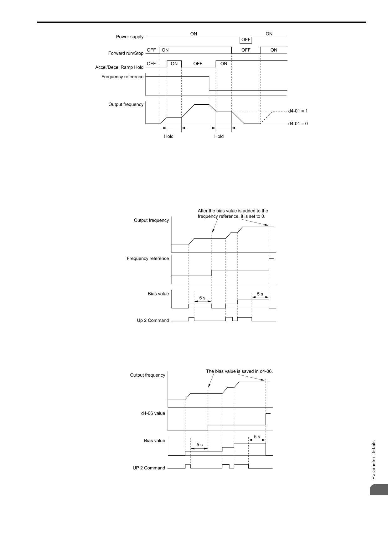
Figure 12.52 Frequency Reference Hold with Accel/Decel Hold Function
• Up/Down Command
When you clear the Run command or de-energize the drive, it will save the frequency reference value. The drive
will use the saved value as the frequency reference when it restarts.
• Up/Down 2 Command with Frequency Reference from Keypad
When a Run command is active and you release the Up/Down 2 command for longer than 5 s, the drive adds the
Up/Down 2 bias value to the frequency reference and sets it to 0. The drive saves the frequency reference value
to which the bias value was added. The drive will use the new value as the frequency reference when it restarts.
Figure 12.53 Up/Down 2 Example with Reference from Keypad and d4-01 = 1
• Up/Down 2 Command with Frequency Reference from Input Sources Other Than the Keypad
When a Run command is active and you release the Up/Down 2 command for longer than 5 s, the drive will
save the bias value in d4-06 [FRef Bias(Up/Dw2)]. The drive saves the frequency reference + d4-06 as a
frequency reference value. The drive will use the new value as the frequency reference when it restarts.
Figure 12.54 Up/Down 2 Example with Other Reference than Keypad and d4-01 = 1
Note:
12
To use the combination of the frequency reference hold function and the Up/Down 2 function, configure the Up/Down 2 upper limit
[d4-08] and lower limit [d4-09] correctly.
517
12.4 d: REFERENCE
Remove the Saved Frequency Reference Value
The procedure to remove the saved frequency reference value is different for different functions. Use these
methods to remove the value:
• Release the input programmed for Ac/Dec Hold [H1-xx = 17].
• Set an Up or Down command while no Run command is active.
• Use the Up/Down 2 Command to set d4-06 = 0.0 or set d4-06 = 0.0 during stop.
■ d4-03: Up/Dw2 Bias Step Frequency
No.
Default
Name
Description
(Hex.)
(Range)
d4-03
Up/Dw2 Bias Step
V/f
OLV OLV/PM AOLV/PM EZOLV
0.00 Hz
Frequency
(02AA)
Sets the bias that the Up/Down 2 function adds to or subtracts from the frequency reference.
(0.00 - 99.99 Hz)
RUN
The operation is different for different setting values:
• Setting d4-03 = 0.00 Hz
When H1-xx = 65, 66 [d4-03: Up2 Command, d4-03: Dw2 Command] is active, the drive uses the accel/decel
times set in d4-04 [d4-03: Up/Dw2 Ramp Selection] to increase or decrease the bias value.
Figure 12.55 Up/Down 2 Bias when d4-03 = 0.00 Hz
• Setting d4-03 ≠ 0.00 Hz
When H1-xx = 65, 66 [d4-03: Up2 Command, d4-03: Dw2 Command] is active, the drive increases or
decreases the bias in steps for the value set in d4-03. The drive uses the acceleration and deceleration times set
in d4-04.
Figure 12.56 Up/Down 2 Bias when d4-03 ≠ 0.00 Hz
■ d4-04: Up/Dw2 Ramp Selection
No.
Default
Name
Description
(Hex.)
(Range)
d4-04
Up/Dw2 Ramp Selection
V/f
OLV OLV/PM AOLV/PM EZOLV
0
(02AB)
Sets the acceleration and deceleration times for the Up/Down 2 function to apply the bias to the
(0, 1)
frequency reference.
RUN
0 : Current Ac/Dec Time
Use the active acceleration and deceleration times to increase or decrease the bias.
1 : Ac/Dec 4
Use C1-07 [Accel Time 4] and C1-08 [Decel Time 4] to increase or decrease the bias.
518
12.4 d: REFERENCE
■ d4-05: Up/Dw2 Bias Mode Selection
No.
Default
Name
Description
(Hex.)
(Range)
d4-05
Up/Dw2 Bias Mode
V/f
OLV OLV/PM AOLV/PM EZOLV
0
Selection
(02AC)
Sets the function that saves the bias value to the drive when you open or close the two Up2
(0, 1)
Command, Dw2 Command [H1-xx = 65, 66]. Set d4-03 [Up/Dw2 Bias Step Frequency] = 0.00
RUN
before you set this parameter.
0 : Hold@Up=Dw=0
When the two MFDI terminals set for Up2 Command, Dw2 Command [H1-xx = 65, 66] activate or deactivate, the
drive will hold the bias value.
1 : Reset@Up=Dw
When the two MFDI terminals set for Up2 Command, Dw2 Command [H1-xx = 65, 66] activate or deactivate, the
drive will reset the bias value to 0. The drive will use the acceleration and deceleration times set in d4-04 [Up/
Dw2 Ramp Selection] to accelerate and decelerate the motor to the selected output frequency.
■ d4-06: FRef Bias(Up/Dw2)
No.
Default
Name
Description
(Hex.)
(Range)
d4-06
FRef Bias(Up/Dw2)
V/f
OLV OLV/PM AOLV/PM EZOLV
0.0%
(02AD)
Saves the bias value from the Up/Down 2 Command where the Maximum Output Frequency is
(-99.9 - +100.0%)
100%.
The Up/Down 2 function setting changes the function of d4-06:
Note:
When the keypad sets the frequency reference, you do not usually use parameter d4-06.
• When d4-01 = 0 [FRef Hold Selection = Disabled] and a source other than the keypad sets the frequency
reference, the drive adds the value set in d4-06 to the frequency reference. If the value set in d4-06 is a negative
number, the drive will subtract it from frequency reference.
• When d4-01 = 1 [Enabled] and a source other than the keypad sets the frequency reference, the drive will store
the bias value adjusted with the Up/Down 2 command in d4-06 5 seconds after you release the Up/Down 2
command. The drive adds or subtracts the value set in d4-06 to the frequency reference.
Conditions that Reset or Disable d4-06
The drive resets and disables the bias value in these conditions:
• d4-01 = 0 and the Run command was cleared.
• H1-xx = 65, 66 [MFDI Function Select = Up2 Command, Dw2 Command] is not set.
• The frequency reference source was changed.
This includes switching LOCAL/REMOTE and multi-step speed reference.
• A digital input changed the frequency reference value.
• d4-03 [Up/Dw2 Bias Step Frequency] = 0 and d4-05 = 1 [Up/Dw2 Bias Mode Selection = Reset@Up=
DwReset when Neither / Both Closed], and the two MFDI terminals set for H1-xx = 65/66 [Up2 Command/Dw2
Command] are activated or deactivated.
• The value of E1-04 [Max Output Frequency] was changed.
■ d4-07: Analog FRef Fluctuate Limit
No.
Default
Name
Description
(Hex.)
(Range)
d4-07
Analog FRef Fluctuate
V/f
OLV OLV/PM AOLV/PM EZOLV
1.0%
Limit
(02AE)
If the frequency reference changes for more than the level set to this parameter, then the bias
(0.1
- 100.0%)
value will be held. The value is set as a percentage of the Maximum Output Frequency.
RUN
Handles frequency reference changes while H1-xx = 65, 66 [Up2 Command, Dw2 Command] is activated. When
the frequency reference changes for more than the level set in d4-07, the drive will hold the bias value, and the
drive will accelerate or decelerate to the frequency reference. When the drive is at the frequency reference, it
releases the bias hold and the bias follows the Up/Down 2 input commands.
This parameter is applicable only when an analog or pulse input sets the frequency reference.
12
519
12.4 d: REFERENCE
■ d4-08: Up/Dw2 Bias Upper Limit
No.
Default
Name
Description
(Hex.)
(Range)
d4-08
Up/Dw2 Bias Upper Limit
V/f
OLV OLV/PM AOLV/PM EZOLV
100.0%
(02AF)
Sets the upper limit of the Up/Down 2 bias as a percentage of the Maximum Output Frequency.
(0.0
- 100.0%)
RUN
The drive saves the set bias upper limit in d4-06 [FRef Bias(Up/Dw2)]. Set d4-08 an applicable value before you
use the Up/Down 2 function.
Note:
When d4-01 = 1 [FRef Hold Selection = Enabled] and b1-01 = 0 [Freq. Ref. Sel. 1 = Keypad], the drive will add the bias value to the
frequency reference when it does not receive an Up/Down 2 command for 5 s. Then the drive will reset the value to 0 at which time you
can increase the bias to the limit set in d4-08 again.
■ d4-09: Up/Dw2 Bias Lower Limit
No.
Default
Name
Description
(Hex.)
(Range)
d4-09
Up/Dw2 Bias Lower Limit
V/f
OLV OLV/PM AOLV/PM EZOLV
0.0%
(02B0)
Sets the lower limit of the Up/Down 2 bias as a percentage of the Maximum Output Frequency.
(-99.9 - 0.0%)
RUN
The drive saves the set bias lower limit in d4-06 [FRef Bias(Up/Dw2)]. Set d4-09 to an applicable value before
you use the Up/Down 2 function.
Note:
When d4-01 = 1 [FRef Hold Selection = Enabled] and b1-01 = 0 [Freq. Ref. Sel. 1 = Keypad], the drive will add the bias value to the
frequency reference when it does not receive an Up/Down 2 command for 5 s. Then the drive will reset the value to 0.
If you increase the bias with the Up 2 command and d4-09 = 0, you cannot use a Down 2 command to decrease the frequency reference.
To decrease speed in this condition, set a negative lower limit in d4-09.
■ d4-10: Up/Dw Frq Low Limit Select
No.
Default
Name
Description
(Hex.)
(Range)
d4-10
Up/Dw Frq Low Limit
V/f
OLV OLV/PM AOLV/PM EZOLV
0
Select
(02B6)
Sets the lower frequency limit for the Up/Down function.
(0, 1)
0 : d2-02/Analog (larger level)
The higher value between d2-02 [FRef Lower Limit] and an analog input programmed for Frequency Reference
[H3-02, H3-10 = 0] sets the lower frequency reference limit.
Note:
When you use Ext Ref 1/2 [H1-xx = 9] to switch between the Up/Down function and an analog input as the reference source, the analog
value becomes the lower reference limit when the Up/Down command is active. Set d4-10 = 1 to isolate the Up/Down function and the
analog input value.
1 : d2-02
You can only use d2-02 to set the lower limit of the frequency reference.
■ d4-11: Bi-Dir Out Selection
No.
Default
Name
Description
(Hex.)
(Range)
d4-11
Bi-Dir Out Selection
V/f
OLV OLV/PM AOLV/PM EZOLV
0
(02B7)
Sets the function that changes the frequency reference to a Bi-Directional internal frequency
(0, 1)
reference.
0 : Disabled
The drive will not change the frequency reference or PID output value to Bi-Directional internal frequency
reference.
When the frequency reference or PID output value is 0% to 100% of the maximum output frequency, the drive
runs the motor in the set direction.
1 : Enabled
Changes the frequency reference or PID output value to Bi-Directional output.
520
12.4 d: REFERENCE
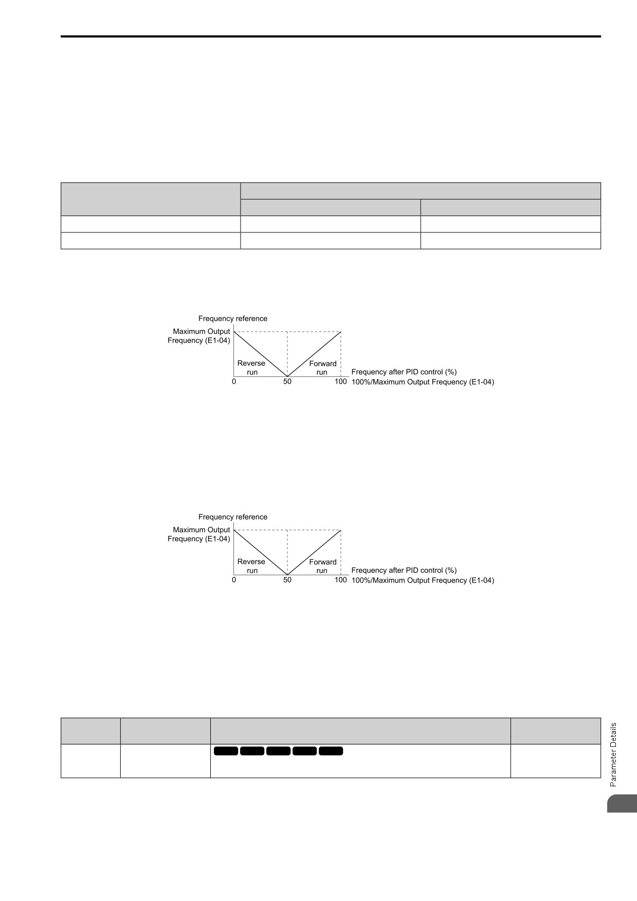
When the frequency reference or PID output value is 0% to 50%, the drive reverses the motor in the set direction.
When the frequency reference or PID output value is 50% to 100%, the drive operates the motor in the set
direction.
Note:
When you use the Bi-Directional function with PID control, you can use an MFDI terminal set for PID BiDir [H1-xx = 7A] to enable/
disable the Bi-Directional function.
Table 12.27 shows how the drive operates when you use the PID control function with the Bi-Directional function
and d4-11 = 1.
Table 12.27 Bi-Directional Function Operation Conditions
Status of MFDI Terminal Set for 7A [PID BiDir]
b5-01 [PID Enable] Setting
ON
OFF
b5-01 = 0 [Disabled]
Bi-Directional function enabled
Bi-Directional function enabled
b5-01 = 1 [Enabled]
Bi-Directional function enabled
Normal operation (Bi-Directional function disables)
• When PID Control is Disabled or H1-xx = 6A [MFDI Function Select = PID Disable] is Activated
When the frequency reference is 0% to 50%, the drive reverses the motor in the set direction. When the
frequency reference is 50% to 100%, the drive runs the motor in the set direction. Figure 12.57 shows the
frequency reference change at this time. This is an example of operation when the Forward Run command is
input.
Figure 12.57 Frequency Reference Transition when PID Control is Disabled or PID Disable is ON
Note:
When b1-04 = 1 [Reverse Operation Selection = Reverse Disabled], the drive will not run in Reverse. The frequency reference limit is
0 Hz.
• When PID Control is Enabled and H1-xx = 7A [PID BiDir] is Activated
When the frequency reference is 0% to 50% after PID control execution, the drive runs the motor opposite of
the set direction. When the frequency reference is 50% to 100%, the drive runs the motor in the set direction.
Figure 12.58 shows the frequency reference change at this time. This is an example of operation when the
Forward Run command is input.
Figure 12.58 Frequency Reference Transition when PID Control and PID Bi-Directional are Enabled
Note:
When b1-04 = 1, the drive will not run the motor in Reverse. The frequency reference limit is 0 Hz.
• When PID Control is Enabled and H1-xx = 7A is Deactivated
The Bi-Directional function is disabled. When the frequency reference is a negative value after PID control
execution, the drive runs the motor opposite of the set direction. The frequency reference value is an absolute
value.
■ d4-12: Stop Position Gain
No.
Default
Name
Description
(Hex.)
(Range)
d4-12
Stop Position Gain
V/f
OLV OLV/PM AOLV/PM EZOLV
1.00
(02B8)
Sets the gain to adjust the stopping accuracy. Set this parameter when b1-03 = 9 [Stopping
(0.50
- 2.55)
Method Selection = Distance Stop].
If the motor stops before the necessary stop position, increase the setting value. If the length of time for the motor
to stop is too long, decrease the setting value.
12
521
12.4 d: REFERENCE
◆ d6: FIELD WEAKENING / FORCING
d6 parameters set the field weakening and field forcing functions.
The field weakening function decreases the energy consumption of the motor. It decreases the output voltage of
the drive to a set level. The function decreases the motor excitation current inversely proportional to speed in a
constant output range, and does not let the induced voltage of the motor become more than the power supply
voltage. To enable this function, set Field weakening [H1-xx = 44] ON.
Note:
Use the Field Weakening function in constant light-load applications. To control the energy consumption of the motor for other load
conditions, use the parameters b8: ENERGY SAVING.
The Field Forcing function adjusts the delaying influence of the motor time constant when the drive changes the
excitation current reference and it also increases motor responsiveness. This function uses a high motor excitation
current reference for drive start-up only to help develop actual motor excitation current. Enable the Field Forcing
function to increase motor responsiveness.
Note:
You cannot use Field Forcing during DC Injection Braking.
■ d6-01: Field Weak Level
No.
Default
Name
Description
(Hex.)
(Range)
d6-01
Field Weak Level
V/f
OLV OLV/PM AOLV/PM EZOLV
80%
(02A0)
Sets the drive output voltage as a percentage of E1-05 [Field Force Selection] when H1-xx = 44
(0 - 100%)
[Field weakening] is activated.
■ d6-02: Field Weak FqLimit
No.
Default
Name
Description
(Hex.)
(Range)
d6-02
Field Weak FqLimit
V/f
OLV OLV/PM AOLV/PM EZOLV
0.0 Hz
(02A1)
Sets the minimum output frequency to start field weakening.
(0.0 - 590.0 Hz)
Make sure that these two conditions are correct to enable the Field Weakening command:
• The output frequency ≥ d6-02.
• There is a speed agreement status.
■ d6-03: Field Force Selection
No.
Default
Name
Description
(Hex.)
(Range)
d6-03
Field Force Selection
V/f
OLV OLV/PM AOLV/PM EZOLV
0
(02A2)
Sets the field forcing function.
(0, 1)
0 : Disabled
1 : Enabled
■ d6-06: Field Force Limit
No.
Default
Name
Description
(Hex.)
(Range)
d6-06
Field Force Limit
V/f
OLV OLV/PM AOLV/PM EZOLV
400%
(02A5)
Sets the limit value for field forcing to increase the motor excitation current reference as a
(100 - 400%)
percentage of E2-03 [Mot No-Load Current]. Usually it is not necessary to change this setting.
Note:
You cannot use Field Forcing during DC Injection Braking.
◆ d7: OFFSET FREQUENCY
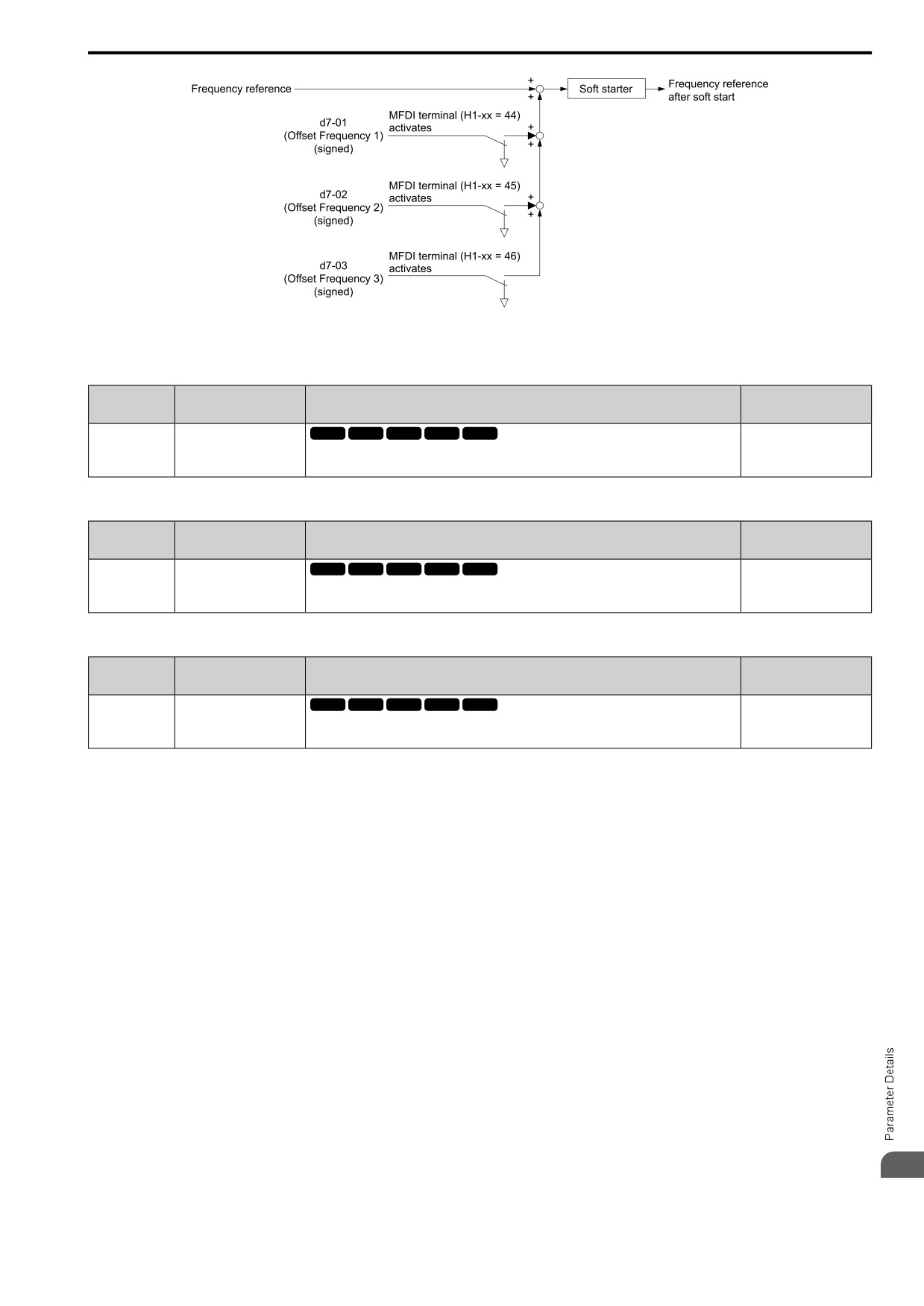
The drive will use 3 digital signal inputs, to add or subtract the set frequency (Offset frequency) to/from the
frequency reference and correct the speed. The drive uses the terminal set in H1-xx = 0E to 10 [MFDI Function
Select = Offset Frq 1 to Offset Frq 3] to set the Offset frequency. When you close more than one input at the same
time, the drive adds the selected offset values together.
522
12.4 d: REFERENCE
Figure 12.59 Offset Frequency Operation
■ d7-01: Offset Frq 1
No.
Default
Name
Description
(Hex.)
(Range)
d7-01
Offset Frq 1
V/f
OLV OLV/PM AOLV/PM EZOLV
0.0%
(02B2)
Uses H1-xx = 0E [MFDI Function Select = Offset Frq 1] as a percentage of the Maximum Output
(-100.0 - +100.0%)
Frequency to add or subtract the set frequency to/from the frequency reference.
RUN
■ d7-02: Offset Frq 2
No.
Default
Name
Description
(Hex.)
(Range)
d7-02
Offset Frq 2
V/f
OLV OLV/PM AOLV/PM EZOLV
0.0%
(02B3)
Uses H1-xx = 0F [MFDI Function Select = Offset Frq 2] as a percentage of the Maximum Output
(-100.0 - +100.0%)
Frequency to add or subtract the set frequency to/from the frequency reference.
RUN
■ d7-03: Offset Frq 3
No.
Default
Name
Description
(Hex.)
(Range)
d7-03
Offset Frq 3
V/f
OLV OLV/PM AOLV/PM EZOLV
0.0%
(02B4)
Uses H1-xx = 10 [MFDI Function Select = Offset Frq 3] as a percentage of the Maximum Output
(-100.0 - +100.0%)
Frequency to add or subtract the set frequency to/from the frequency reference.
RUN
12
523
12.5 E: MOTOR
12.5
E: MOTOR
E parameters cover drive input voltage, V/f pattern, and motor parameters.
◆ E1: V/F PARAMETER MOTOR 1
E1 parameters are used to set the drive input voltage and motor V/f characteristics. To switch drive operation
from one motor to another motor, set the V/f characteristics for motor 1.
■ V/f Pattern Settings
The drive uses a V/f pattern to adjust the output voltage relative to the frequency reference.
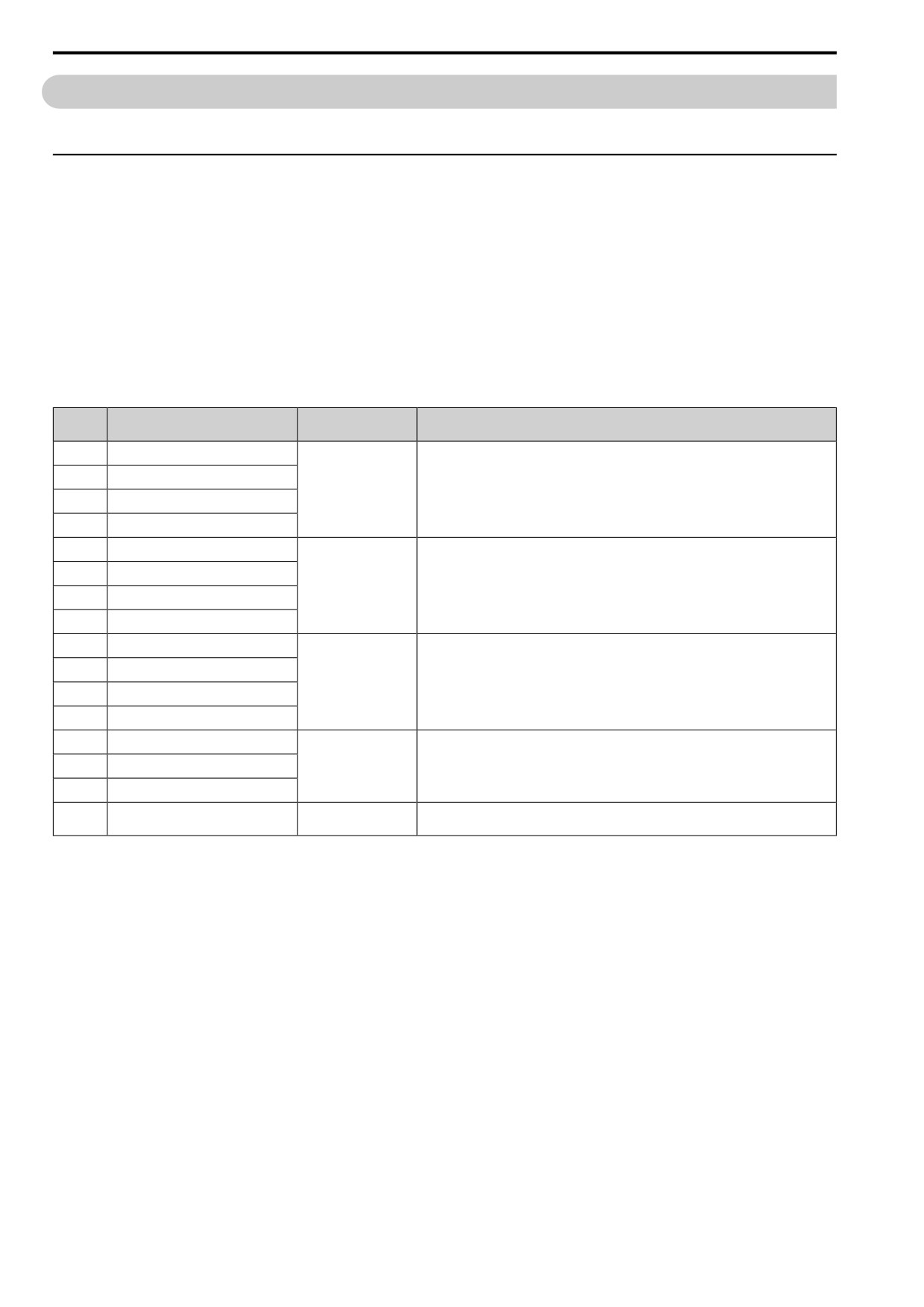
This product has been preconfigured with 15 voltage/frequency (V/f) patterns. Use E1-03 [V/f Pattern Selection]
to select the V/f pattern that is appropriate for the application.
Additionally, one custom V/f pattern is available. Set E1-03 = F [Custom] and then manually set parameters E1-
04 to E1-10.
Table 12.28 Predefined V/f Patterns
Setting
Specification
Characteristic
Application
Value
0
CT_50-50Hzmax
Constant torque
For general purpose applications. This pattern is used when the load torque is constant without
any rotation speed such as that used for linear conveyor systems.
1
CT_60-60Hzmax
2
CT_50-60Hzmax
3
CT_60-72Hzmax
4
VT_50-35HzmidV
Derated Torque
This pattern is used for torque loads proportional to 2 or 3 times the rotation speed, such as is
Characteristics
the case with fans and pumps.
5
VT_50-50HzmidV
6
VT_60-35HzmidV
7
VT_60-50HzmidV
8
HT_50Hz_125 V
High starting torque
This pattern is used when strong torque is required during startup.
9
HTrq50Hz-165 V
A
HTrq60Hz-125V
B
HT_60Hz-165V
C
HF_60-90Hzmax
Constant output
This pattern is used to rotate motors at greater than 60 Hz. Output voltage is constant when
operating at greater than 60 Hz.
D
HF_60-120Hzmax
E
HF_60-180Hzmax
Custom
Constant torque
Enables a custom V/f pattern by changing E1-04 to E1-13 [V/f Pattern for Motor 1]. The
F
default settings for E1-04 to E1-13 are the same as Setting Value 1 [CT_60-60Hzmax].
524
12.5 E: MOTOR
Note:
Be aware of the following points when manually setting V/f patterns.
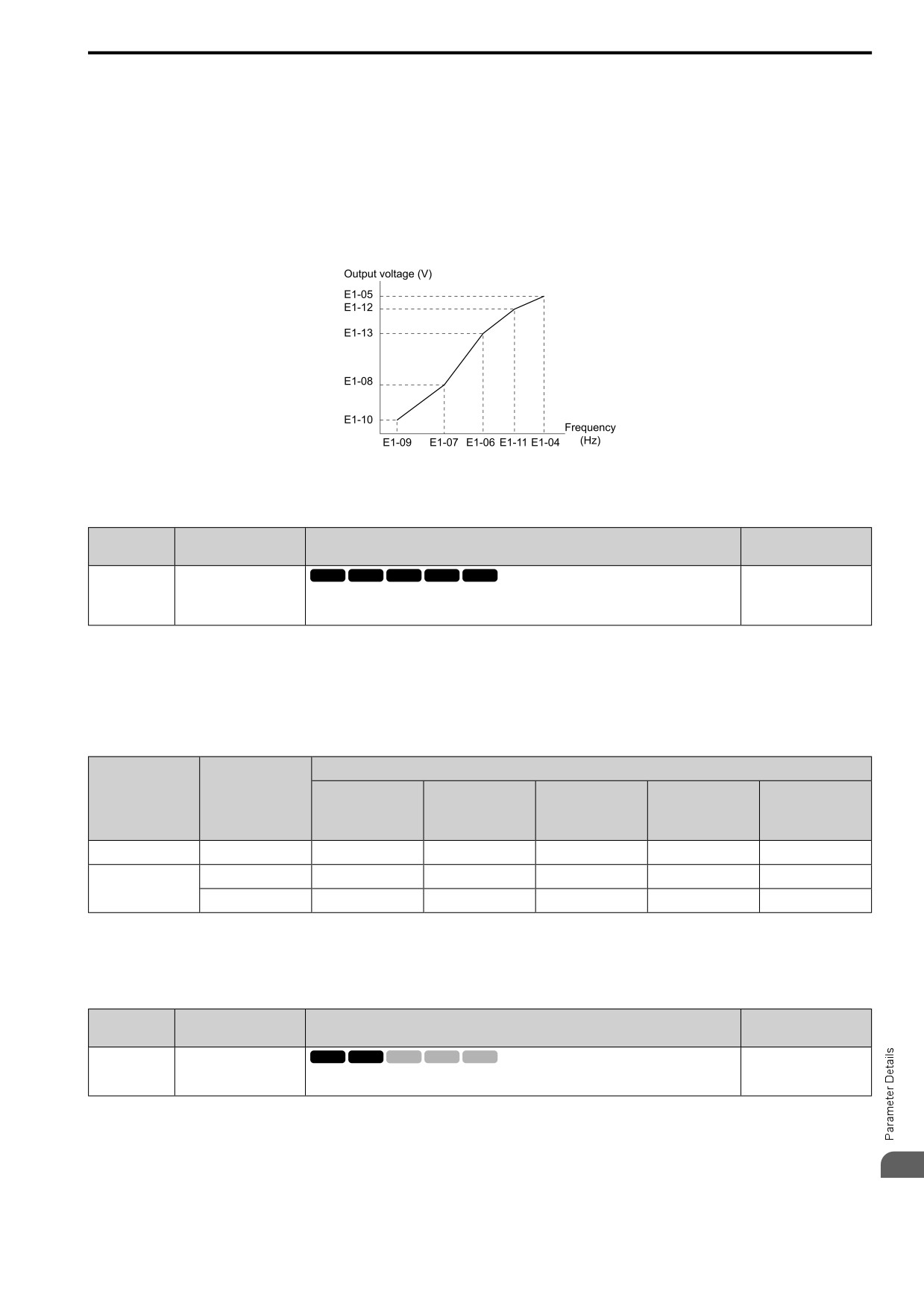
• To set linear V/f characteristics at frequencies lower than E1-06 [Base Frequency], set E1-07 = E1-09 [Mid A Frequency = Min Output
Frequency]. In this application, the drive ignores E1-08 [Mid A Voltage].
• Set the five frequencies as specified by these rules: Incorrect settings will cause oPE10 [V/f Data Setting Error].
E1-09 ≤ E1-07 < E1-06 ≤ E1-11 ≤ E1-04 [Min Output Frequency ≤ Mid A Frequency < Base Frequency ≤ Mid B Frequency ≤ Max
Output Frequency]
• Setting E1-11 = 0 [Mid B Frequency = 0 Hz] disables E1-12 [Min Output Voltage]. Ensure that the four frequencies are set according
to the following rules;
E1-09 ≤ E1-07 < E1-06 ≤ E1-04
• When you use A1-03 [Init Parameters] to initialize the drive, it will not reset E1-03.
Figure 12.60 V/f Pattern
■ E1-01: Input AC Supply Voltage
No.
Default
Name
Description
(Hex.)
(Range)
E1-01
Input AC Supply Voltage
V/f
OLV OLV/PM AOLV/PM
EZOLV
200 V Class: 230 V, 400 V:
400 V
(0300)
Sets the drive input voltage.
(200 V Class: 155 to 255 V,
400 V Class: 310 to 510 V)
NOTICE: Set parameter E1-01 to align with the drive input voltage (not motor voltage). If this parameter is incorrect, the
protective functions of the drive will not operate correctly and it can cause damage to the drive.
Values Related to the Drive Input Voltage
The value set in E1-01 is the base value that the drive uses for the motor protective functions in Table 12.29. With
a 400 V class drive, the detection level changes for some motor protective functions.
Table 12.29 Values Related to the Drive Input Voltage
Approximate Values
BTR Operation
Voltage
E1-01 Setting
L2-05
L2-11
L3-17
Level
ov Detection Level
[E1-01: UV
[KEB DC Volt
[DCBus Regul.
(rr Detection Level)
*1
Detection Lvl (Uv1)]
Setpoint]
Level]
200 V class
All settings
410 V
394 V
190 V
260 V
375 V
Setting value ≥ 400 V
820 V
788 V
380 V
500 V
750 V
400 V class
Setting value < 400 V
820 V
788 V
350 V
460 V
750 V
*1
This is the protection function enabled in drives with built-in braking transistors. These values show the level that will trigger the
built-in braking transistor. Refer to ““Braking Unit, Braking Resistor Unit Instruction Manual (TOBPC72060001)”” for more
information.
■ E1-03: V/f Pattern Selection
No.
Default
Name
Description
(Hex.)
(Range)
V/f
OLV OLV/PM AOLV/PM EZOLV
E1-03
V/f Pattern Selection
F
(0302)
Sets the V/f pattern for the drive and motor. You can use one of the preset patterns or you can
(Determined by A1-02)
make a custom pattern.
Note:
• When A1-02 = 2 [Control Method = OLVector], settings 0 to E are not available.
• Set the correct V/f pattern for the application and operation area. An incorrect V/f pattern can decrease motor torque and increase
current from overexcitation.
12
• Parameter A1-03 [Init Parameters] will not reset the value of E1-03.
0 : CT_50-50Hzmax
525
12.5 E: MOTOR
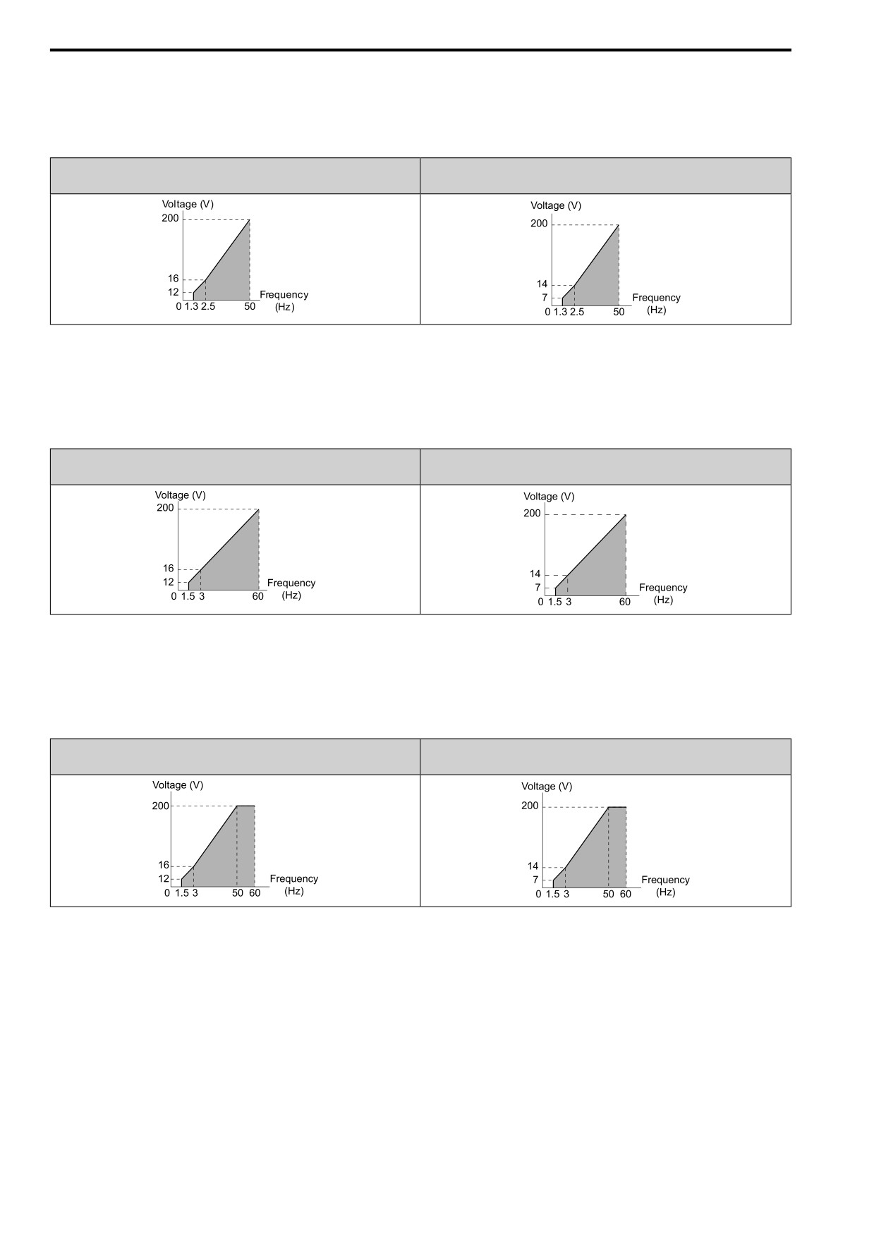
Use this constant torque pattern for general applications. This pattern is used when the load torque is constant
without any rotation speed such as that used for linear conveyor systems.
Note:
The voltage values in the figures are for 200 V class drives. Multiply the values by 2 for 400 V class drives.
HD : 2001 - 2021, B001 - B018, 4001 - 4012
HD : 2030 - 2082, 4018 - 4060
ND : 2001 - 2018, B001 - B012, 4001 - 4009
ND : 2021 - 2082, 4012 - 4060
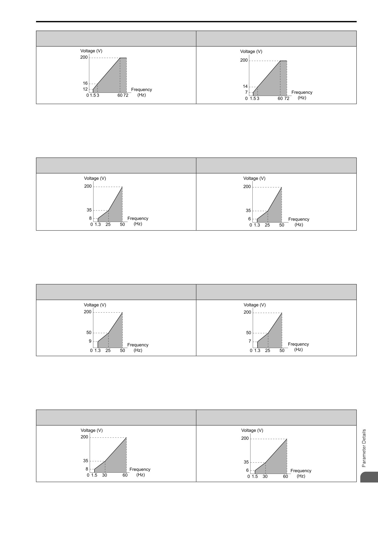
1 : CT_60-60Hzmax
Use this constant torque pattern for general applications. This pattern is used when the load torque is constant
without any rotation speed such as that used for linear conveyor systems.
Note:
The voltage values in the figures are for 200 V class drives. Multiply the values by 2 for 400 V class drives.
HD : 2001 - 2021, B001 - B018, 4001 - 4012
HD : 2030 - 2082, 4018 - 4060
ND : 2001 - 2018, B001 - B012, 4001 - 4009
ND : 2021 - 2082, 4012 - 4060
2 : CT_50-60Hzmax
Use this constant torque pattern for general applications. This pattern is used when the load torque is constant
without any rotation speed such as that used for linear conveyor systems.
Note:
The voltage values in the figures are for 200 V class drives. Multiply the values by 2 for 400 V class drives.
HD : 2001 - 2021, B001 - B018, 4001 - 4012
HD : 2030 - 2082, 4018 - 4060
ND : 2001 - 2018, B001 - B012, 4001 - 4009
ND : 2021 - 2082, 4012 - 4060
3 : CT_60-72Hzmax
Use this constant torque pattern for general applications. This pattern is used when the load torque is constant
without any rotation speed such as that used for linear conveyor systems.
Note:
The voltage values in the figures are for 200 V class drives. Multiply the values by 2 for 400 V class drives.
526
12.5 E: MOTOR
HD : 2001 - 2021, B001 - B018, 4001 - 4012
HD : 2030 - 2082, 4018 - 4060
ND : 2001 - 2018, B001 - B012, 4001 - 4009
ND : 2021 - 2082, 4012 - 4060
4 : VT_50-35HzmidV
Use this derated torque pattern for torque loads proportional to three times the rotation speed. For example, fans
and pumps.
Note:
The voltage values in the figures are for 200 V class drives. Multiply the values by 2 for 400 V class drives.
HD : 2001 - 2021, B001 - B018, 4001 - 4012
HD : 2030 - 2082, 4018 - 4060
ND : 2001 - 2018, B001 - B012, 4001 - 4009
ND : 2021 - 2082, 4012 - 4060
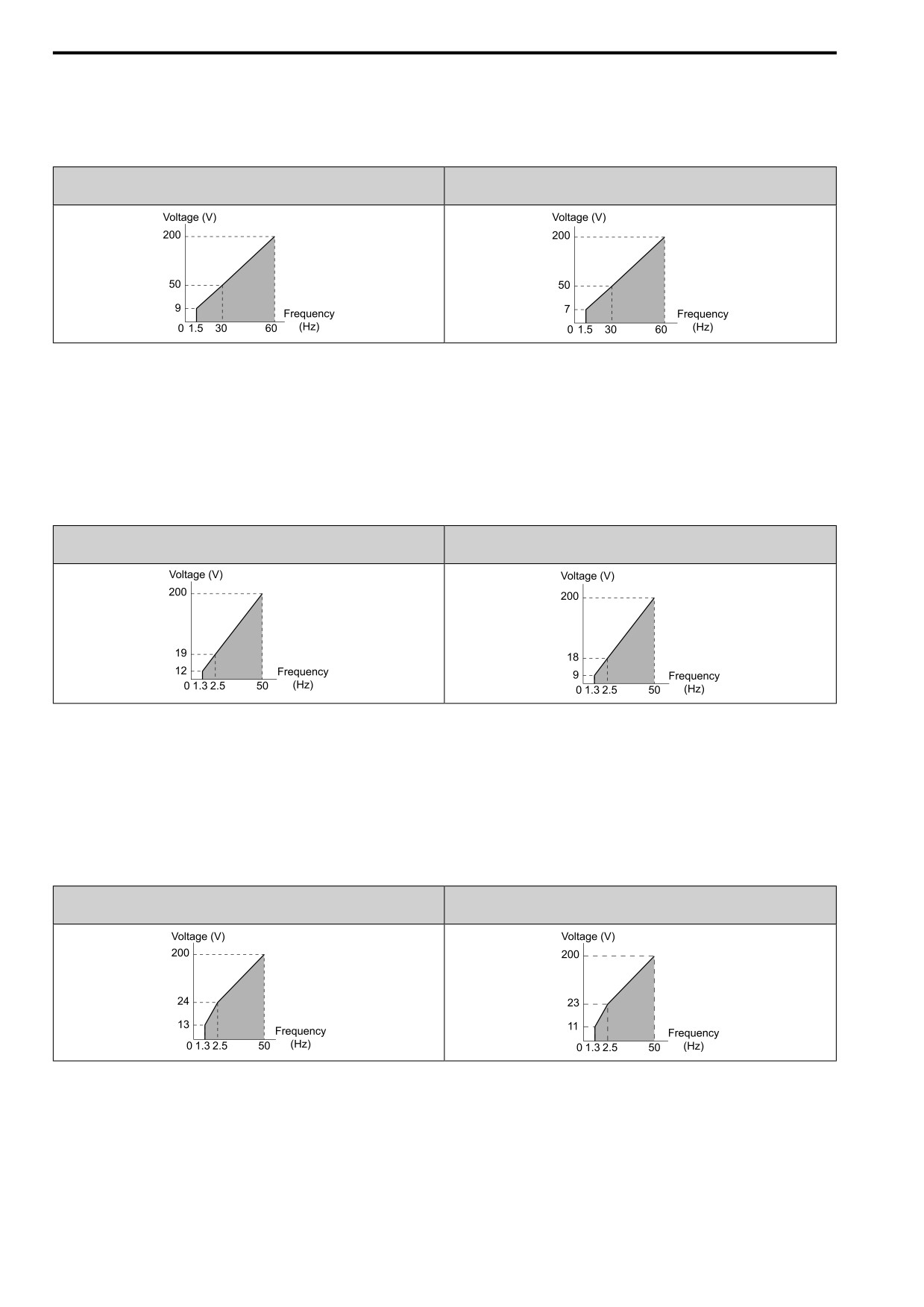
5 : VT_50-50HzmidV
Use this derated torque pattern for torque loads proportional to two times the rotation speed. For example, fans
and pumps.
Note:
The voltage values in the figures are for 200 V class drives. Multiply the values by 2 for 400 V class drives.
HD : 2001 - 2021, B001 - B018, 4001 - 4012
HD : 2030 - 2082, 4018 - 4060
ND : 2001 - 2018, B001 - B012, 4001 - 4009
ND : 2021 - 2082, 4012 - 4060
6 : VT_60-35HzmidV
Use this derated torque pattern for torque loads proportional to three times the rotation speed. For example, fans
and pumps.
Note:
The voltage values in the figures are for 200 V class drives. Multiply the values by 2 for 400 V class drives.
HD : 2001 - 2021, B001 - B018, 4001 - 4012
HD : 2030 - 2082, 4018 - 4060
ND : 2001 - 2018, B001 - B012, 4001 - 4009
ND : 2021 - 2082, 4012 - 4060
12
7 : VT_60-50HzmidV
527
12.5 E: MOTOR
Use this derated torque pattern for torque loads proportional to two times the rotation speed. For example, fans
and pumps.
Note:
The voltage values in the figures are for 200 V class drives. Multiply the values by 2 for 400 V class drives.
HD : 2001 - 2021, B001 - B018, 4001 - 4012
HD : 2030 - 2082, 4018 - 4060
ND : 2001 - 2018, B001 - B012, 4001 - 4009
ND : 2021 - 2082, 4012 - 4060
8 : HT_50Hz_125 V
Use this pattern when moderate torque is necessary during start up.
Select this pattern only in these conditions:
• The wiring distance between the drive and motor is 150 m (492.1 ft) minimum
• There is an AC reactor connected to the drive output.
Note:
The voltage values in the figures are for 200 V class drives. Multiply the values by 2 for 400 V class drives.
HD : 2001 - 2021, B001 - B018, 4001 - 4012
HD : 2030 - 2082, 4018 - 4060
ND : 2001 - 2018, B001 - B012, 4001 - 4009
ND : 2021 - 2082, 4012 - 4060
9 : HTrq50Hz-165 V
Use this pattern when high torque is necessary during start up.
Select this pattern only in these conditions:
• The wiring distance between the drive and motor is 150 m (492.1 ft) minimum
• There is an AC reactor connected to the drive output.
Note:
The voltage values in the figures are for 200 V class drives. Multiply the values by 2 for 400 V class drives.
HD : 2004 - 2021, 4002 - 4012
HD : 2030 - 2211, 4018 - 4103
ND : 2004 - 2018, 4002 - 4009
ND : 2021 - 2169, 4012 - 4089
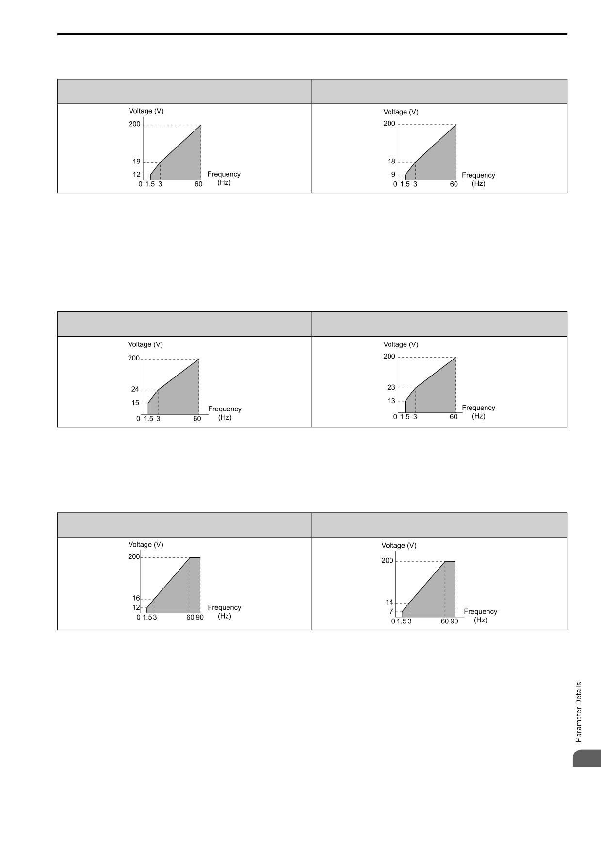
A : HTrq60Hz-125V
Use this pattern when moderate torque is necessary during start up.
Select this pattern only in these conditions:
• The wiring distance between the drive and motor is 150 m (492.1 ft) minimum
• There is an AC reactor connected to the drive output.
528
12.5 E: MOTOR
Note:
The voltage values in the figures are for 200 V class drives. Multiply the values by 2 for 400 V class drives.
HD : 2001 - 2021, B001 - B018, 4001 - 4012
HD : 2030 - 2082, 4018 - 4060
ND : 2001 - 2018, B001 - B012, 4001 - 4009
ND : 2021 - 2082, 4012 - 4060
B : HT_60Hz-165V
Use this pattern when high torque is necessary during start up.
Select this pattern only in these conditions:
• The wiring distance between the drive and motor is 150 m (492.1 ft) minimum
• There is an AC reactor connected to the drive output.
Note:
The voltage values in the figures are for 200 V class drives. Multiply the values by 2 for 400 V class drives.
HD : 2001 - 2021, B001 - B018, 4001 - 4012
HD : 2030 - 2082, 4018 - 4060
ND : 2001 - 2018, B001 - B012, 4001 - 4009
ND : 2021 - 2082, 4012 - 4060
C : HF_60-90Hzmax
Use this constant output pattern to rotate motors at more than 60 Hz. Output voltage is constant when you operate
at more than 60 Hz.
Note:
The voltage values in the figures are for 200 V class drives. Multiply the values by 2 for 400 V class drives.
HD : 2001 - 2021, B001 - B018, 4001 - 4012
HD : 2030 - 2082, 4018 - 4060
ND : 2001 - 2018, B001 - B012, 4001 - 4009
ND : 2021 - 2082, 4012 - 4060
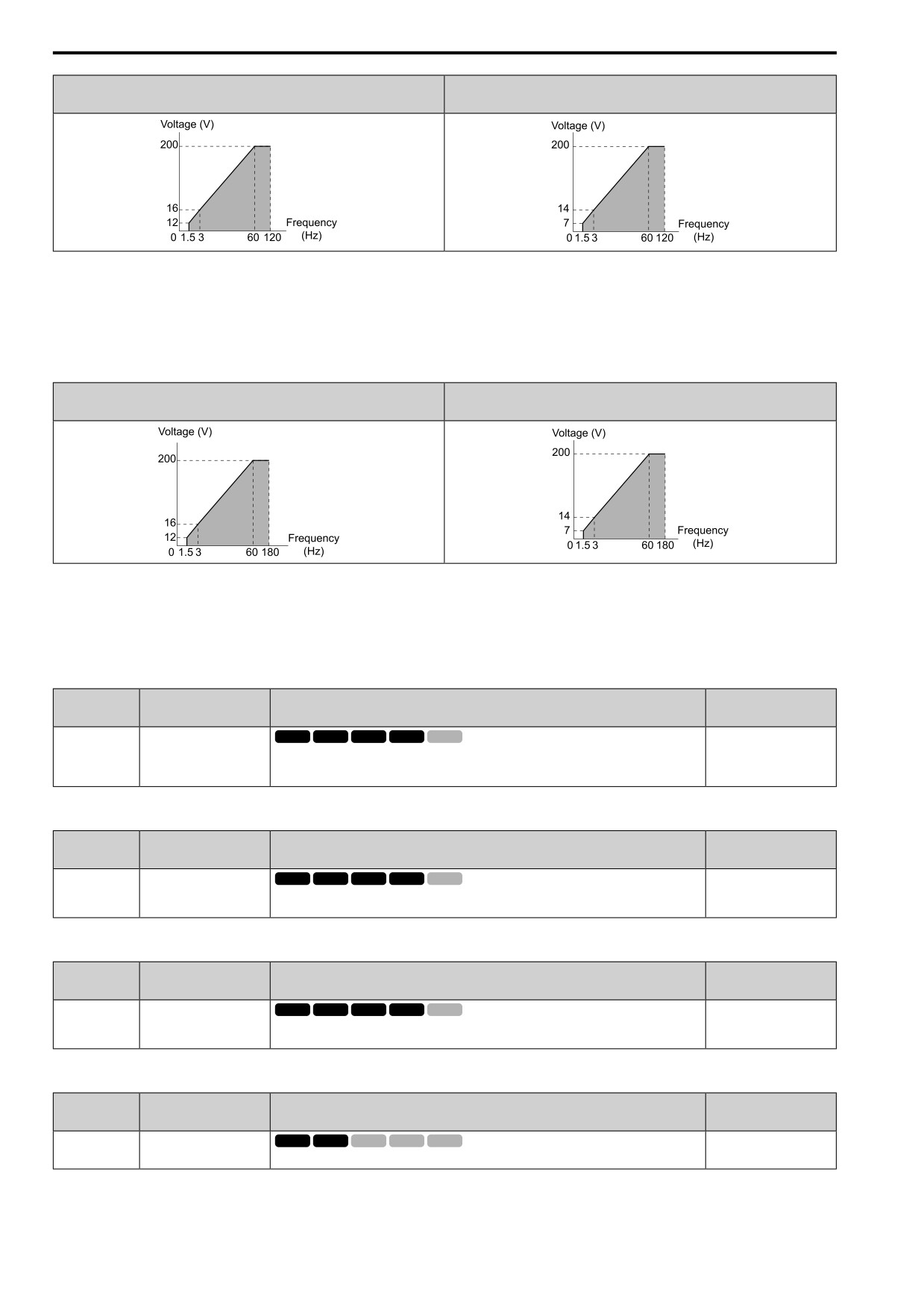
D : HF_60-120Hzmax
Use this constant output pattern to rotate motors at more than 60 Hz. Output voltage is constant when you operate
at more than 60 Hz.
Note:
The voltage values in the figures are for 200 V class drives. Multiply the values by 2 for 400 V class drives.
12
529
12.5 E: MOTOR
HD : 2001 - 2021, B001 - B018, 4001 - 4012
HD : 2030 - 2082, 4018 - 4060
ND : 2001 - 2018, B001 - B012, 4001 - 4009
ND : 2021 - 2082, 4012 - 4060
E : HF_60-180Hzmax
Use this constant output pattern to rotate motors at more than 60 Hz. Output voltage is constant when you operate
at more than 60 Hz.
Note:
The voltage values in the figures are for 200 V class drives. Multiply the values by 2 for 400 V class drives.
HD : 2001 - 2021, B001 - B018, 4001 - 4012
HD : 2030 - 2082, 4018 - 4060
ND : 2001 - 2018, B001 - B012, 4001 - 4009
ND : 2021 - 2082, 4012 - 4060
F : Custom
Set E1-04 to E1-13 [V/f Pattern for Motor 1] to set the values for this custom pattern.
The default settings are the same as Setting Value 0 [CT_50-50Hzmax].
■ E1-04: Max Output Frequency
No.
Default
Name
Description
(Hex.)
(Range)
E1-04
Max Output Frequency
V/f
OLV OLV/PM AOLV/PM EZOLV
Determined by A1-02 and
E5-01
(0303)
Sets the maximum output frequency for the V/f pattern.
(Determined by A1-02 and
E5-01)
■ E1-05: Max Output Voltage
No.
Default
Name
Description
(Hex.)
(Range)
E1-05
Max Output Voltage
V/f
OLV OLV/PM AOLV/PM EZOLV
200.0
(0304)
Sets the maximum output voltage for the V/f pattern.
(200 V Class: 0.0 - 255.0 V,
400 V Class: 0.0 - 510.0 V)
■ E1-06: Base Frequency
No.
Default
Name
Description
(Hex.)
(Range)
E1-06
Base Frequency
V/f
OLV OLV/PM AOLV/PM EZOLV
Determined by A1-02 and
E5-01
(0305)
Sets the base frequency for the V/f pattern.
(0.0 - E1-04)
■ E1-07: Mid A Frequency
No.
Default
Name
Description
(Hex.)
(Range)
E1-07
Mid A Frequency
V/f
OLV OLV/PM AOLV/PM EZOLV
Determined by A1-02
(0306)
Sets a middle output frequency for the V/f pattern.
(0.0 - E1-04)
530
12.5 E: MOTOR
■ E1-08: Mid A Voltage
No.
Default
Name
Description
(Hex.)
(Range)
E1-08
Mid A Voltage
V/f
OLV OLV/PM AOLV/PM EZOLV
Determined by A1-02,C6-
01 and o2-04
(0307)
Sets a middle output voltage for the V/f pattern.
(200 V Class: 0.0 - 255.0 V,
400 V Class: 0.0 - 510.0 V)
Note:
Default setting is determined by A1-02 [Control Method], C6-01 [ND/HD Duty Selection], and o2-04 [Drive KVA Selection].
■ E1-09: Min Output Frequency
No.
Default
Name
Description
(Hex.)
(Range)
E1-09
Min Output Frequency
V/f
OLV OLV/PM AOLV/PM EZOLV
Determined by A1-02 and
E5-01
(0308)
Sets the minimum output frequency for the V/f pattern.
(Determined by A1-02, E1-
04, and E5-01)
■ E1-10: Min Output Voltage
No.
Default
Name
Description
(Hex.)
(Range)
V/f
OLV OLV/PM AOLV/PM EZOLV
E1-10
Min Output Voltage
Determined by A1-02
(0309)
Sets the minimum output voltage for the V/f pattern.
(200 V Class: 0.0 to 255.0
V, 400 V Class: 0.0 to 510.0
V)
■ E1-11: Mid B Frequency
No.
Default
Name
Description
(Hex.)
(Range)
E1-11
Mid B Frequency
V/f
OLV OLV/PM AOLV/PM EZOLV
0.0 Hz
(030A)
Sets a middle output frequency for the V/f pattern.
(0.0 - E1-04)
Expert
Note:
Set this parameter to 0.0 to disable the function.
■ E1-12: Min Output Voltage
No.
Default
Name
Description
(Hex.)
(Range)
E1-12
Min Output Voltage
V/f
OLV OLV/PM AOLV/PM EZOLV
0.0 V
(030B)
Sets a middle point voltage for the V/f pattern.
(200 V Class: 0.0 to 255.0
V, 400 V Class: 0.0 to 510.0
Expert
V)
Note:
Set this parameter to 0.0 to disable the function.
■ E1-13: Base Voltage
No.
Default
Name
Description
(Hex.)
(Range)
E1-13
Base Voltage
V/f
OLV OLV/PM AOLV/PM EZOLV
0.0 V
(030C)
Sets the base voltage for the V/f pattern.
(200 V Class: 0.0 - 255.0
V,400 V Class: 0.0 - 510.0
Expert
V)
Note:
• After Auto-Tuning, the value of E1-13 = E1-05 [Max Output Voltage].
• When E1-13 = 0.0, use the value of E1-05 to control the voltage.
◆ E2: MOTOR 1 PARAMETERS
E2 parameters are used to set induction motor data. To switch drive operation from one motor to another motor,
12
configure the first motor (motor 1).
531
12.5 E: MOTOR
If Auto-Tuning cannot be performed, set the E2 parameters manually. Performing Auto-Tuning automatically sets
the E2 parameters to the optimal values.
Note:
If A1-02 [Control Method] is set to the following control modes, the keypad does not display E2-xx.
•5 [PM OLVector]
•6 [PM AOLVector]
•8 [EZ Vector]
■ E2-01: Mot Rated Current (FLA)
No.
Default
Name
Description
(Hex.)
(Range)
V/f
OLV OLV/PM AOLV/PM EZOLV
E2-01
Mot Rated Current (FLA)
Determined by o2-04, C6-
01
(030E)
Sets the motor rated current in amps.
(10% to 200% of the drive
rated current)
Note:
• If E2-01 < E2-03 [Mot No-Load Current], the drive will detect oPE02 [Parameter Range Setting Error].
• When the drive model changes, the display units for this parameter also change.
-0.01 A: 2001 to 2042, B001 to B018, 4001 to 4023
-0.1 A: 2056 to 2082, 4031 to 4060
The value set for E2-01 becomes the reference value for motor protection and the torque limit. Enter the motor
rated current written on the motor nameplate. Auto-Tuning the drive will automatically set E2-01 to the value
input for T1-04 [Motor Rated Current].
■ E2-02: Mot Rated Slip
No.
Default
Name
Description
(Hex.)
(Range)
E2-02
Mot Rated Slip
V/f
OLV OLV/PM AOLV/PM EZOLV
Determined by o2-04, C6-
01
(030F)
Sets motor rated slip.
(0.000 - 20.000 Hz)
This parameter value becomes the base slip compensation value. The drive automatically sets this parameter
during Auto-Tuning. When you cannot do Auto-Tuning, calculate the motor rated slip with the information on the
motor nameplate and this formula:
E2-02 = f - (n × p) / 120
• f: Motor rated frequency (Hz)
• n: Rated motor speed (min-1 (r/min))
• p: Number of motor poles
■ E2-03: Mot No-Load Current
No.
Default
Name
Description
(Hex.)
(Range)
V/f
OLV OLV/PM AOLV/PM EZOLV
E2-03
Mot No-Load Current
Determined by o2-04, C6-
01
(0310)
Sets the no-load current for the motor in amps when operating at the rated frequency and the no-
load voltage.
(0 to E2-01)
Note:
When the drive model changes, the display units for this parameter also change.
• 0.01 A: 2001 to 2042, B001 to B018, 4001 to 4023
• 0.1 A: 2056 to 2082, 4031 to 4060
The drive automatically sets this parameter during Auto-Tuning. When you cannot do Auto-Tuning, you can also
use the motor no-load current on the motor test report to enter this value manually. Get the test report from the
motor manufacturer.
Note:
The default setting of the no-load current is for a 4-pole motor recommended by the manufacturer.
532
12.5 E: MOTOR
■ E2-04: Motor Pole Count
No.
Default
Name
Description
(Hex.)
(Range)
E2-04
Motor Pole Count
V/f
OLV OLV/PM AOLV/PM EZOLV
4
(0311)
Sets the number of motor poles.
(2 - 120)
Note:
• When A1-02 = 0 [Control Method = V/f Control], the maximum value is 120.
• When A1-02 = 2 [OLVector], the maximum value is 48.
Auto-Tuning automatically sets this parameter to the value of [Number of Motor Poles].
■ E2-05: Motor L-L Resistance
No.
Default
Name
Description
(Hex.)
(Range)
E2-05
Motor L-L Resistance
V/f
OLV OLV/PM AOLV/PM EZOLV
Determined by o2-04, C6-
01
(0312)
Sets the line-to-line resistance for the motor stator windings.
(0.000 - 65.000 Ω)
Note:
This value is the motor line-to-line resistance. Do not set this parameter with the single-phase resistance.
Auto-Tuning automatically sets this parameter. If you cannot do Auto-Tuning, use the test report from the motor
manufacturer to configure the settings. You can calculate the motor line-to-line resistance with one of these
formulas:
• E-type insulation: [the resistance value (Ω) shown on the test report at 75 °C] × 0.92
• B-type insulation: [the resistance value (Ω) shown on the test report at 75 °C] × 0.92
• F-type insulation: [the resistance value (Ω) shown on the test report at 115 °C] × 0.87
■ E2-06: Motor Leak Inductance
No.
Default
Name
Description
(Hex.)
(Range)
V/f
OLV OLV/PM AOLV/PM EZOLV
E2-06
Motor Leak Inductance
Determined by o2-04, C6-
01
(0313)
Sets the voltage drop from motor leakage inductance when the motor is operating at the rated
frequency and rated current. This value is a percentage of Motor Rated Voltage.
(0.0
- 60.0%)
The drive automatically sets this parameter during Auto-Tuning.
Note:
The motor nameplate does not usually show the quantity of voltage drop. If you do not know the value of the motor leakage inductance,
contact the motor manufacturer to receive a copy of the motor test report.
■ E2-07: Mot Sat Coeff 1
No.
Default
Name
Description
(Hex.)
(Range)
E2-07
Mot Sat Coeff 1
V/f
OLV OLV/PM AOLV/PM EZOLV
0.50
(0314)
Sets the motor iron-core saturation coefficient at 50% of the magnetic flux.
(0.00
- 0.50)
The drive uses this coefficient when it operates with constant output. The drive uses this coefficient when it
operates the motor in the constant output range.
■ E2-08: Mot Sat Coeff 2
No.
Default
Name
Description
(Hex.)
(Range)
E2-08
Mot Sat Coeff 2
V/f
OLV OLV/PM AOLV/PM EZOLV
0.75
(0315)
Sets the motor iron-core saturation coefficient at 75% of the magnetic flux.
(E2-07 - 0.75)
The drive uses this coefficient when it operates with constant output. The drive uses this coefficient when it
operates the motor in the constant output range.
12
533
12.5 E: MOTOR
■ E2-09: Motor Mech Loss
No.
Default
Name
Description
(Hex.)
(Range)
E2-09
Motor Mech Loss
V/f
OLV OLV/PM AOLV/PM EZOLV
0.0%
(0316)
Sets the mechanical loss of the motor. It is set as a percentage of E2-11 [Motor Rated Power
(0.0
- 10.0%)
(kW)]. Usually it is not necessary to change this setting.
Expert
Adjust this parameter in these conditions. The drive adds the configured mechanical loss to the torque reference
value as a torque compensation value:
• There is a large quantity of torque loss from motor bearing friction.
• There is a large quantity of torque loss in fans and pumps.
■ E2-10: Motor Iron Loss
No.
Default
Name
Description
(Hex.)
(Range)
V/f
OLV OLV/PM AOLV/PM EZOLV
E2-10
Motor Iron Loss
Determined by o2-04, C6-
(0317)
Sets the motor iron loss.
01
(0 - 65535 W)
■ E2-11: Motor Rated Power (kW)
No.
Default
Name
Description
(Hex.)
(Range)
E2-11
Motor Rated Power (kW)
V/f
OLV OLV/PM AOLV/PM EZOLV
Determined by o2-04, C6-
01
(0318)
Sets the motor rated output in the units from o1-58 [Mot Capacity Unit].
(0.00 - 650.00 kW)
The drive automatically sets this parameter to the value input for “Motor Rated Power” during Auto-Tuning.
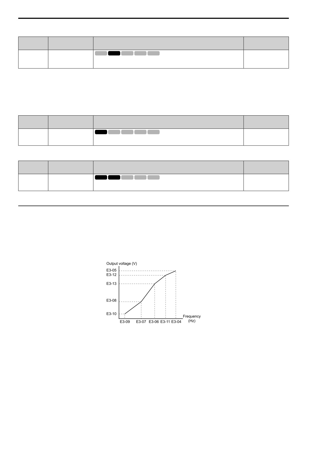
◆ E3: V/F PARAMETER MOTOR 2
E3 parameters set the control mode and V/f pattern used for motor 2.
Note:
V/f preset patterns equivalent to those set with E1-03 [V/f Pattern Selection] are not available for E3 parameters. Use E3-04 [M2 Max
Out Frequency] to E3-10 [M2 Min Out Voltage] to manually set the V/f pattern.
■ Notes on Manually Setting V/f Patterns
Figure 12.61 Motor 2 V/f Pattern Diagram
• To configure a linear V/f pattern at frequencies lower than E3-06 [M2 Base Frequency], set E3-07 = E3-09 [M2
Mid A Frequency = M2 Min Out Frequency]. In this application, the drive ignores E1-08 [M2 Mid A Voltage].
• Set the five frequencies as specified by these rules:
E3-09 ≤ E3-07 < E3-06 ≤ E3-11 ≤ E3-04 [M2 Min Out Frequency ≤ M2 Mid A Frequency < M2 Base
Frequency ≤ M2 Mid B Frequency ≤ M2 Max Out Frequency]
Incorrect settings will trigger oPE10 [V/f Data Setting Error].
• If E3-11 = 0.0 Hz, the drive will ignore the V/f pattern settings.
• When you use A1-03 [Init Parameters] to initialize the drive, the drive will reset the manually set values for E3-
04 to E3-13 [M2 Base Voltage] to default values.
534
12.5 E: MOTOR
■ E3-01: M2 Control Method Selection
No.
Default
Name
Description
(Hex.)
(Range)
E3-01
M2 Control Method
V/f
OLV OLV/PM AOLV/PM EZOLV
0
Selection
(0319)
Sets the control method for motor 2.
(0, 2)
Note:
• When you change this setting, the drive will set all parameters that are dependent on E3-01 to their default settings.
• Parameter L1-01 [Motor Cool Type for OL1 Calc] sets the protection operation of oL1 [Motor Overload] the same as Motor 1.
• When you use parameter A1-03 [Init Parameters] to initialize the drive, this parameter is not reset.
0 : V/f Control
2 : OLVector
■ E3-04: M2 Max Out Frequency
No.
Default
Name
Description
(Hex.)
(Range)
E3-04
M2 Max Out Frequency
V/f
OLV OLV/PM AOLV/PM EZOLV
Determined by E3-01
(031A)
Set the maximum output frequency for the motor 2 V/f pattern.
(40.0 - 590.0 Hz)
■ E3-05: M2 Max Out Voltage
No.
Default
Name
Description
(Hex.)
(Range)
V/f
OLV OLV/PM AOLV/PM EZOLV
E3-05
M2 Max Out Voltage
Determined by E3-01
(031B)
Sets the maximum output voltage for the motor 2 V/f pattern.
(200 V Class: 0.0 - 255.0 V,
400 V Class: 0.0 - 510.0 V)
■ E3-06: M2 Base Frequency
No.
Default
Name
Description
(Hex.)
(Range)
E3-06
M2 Base Frequency
V/f
OLV OLV/PM AOLV/PM EZOLV
Determined by E3-01
(031C)
Sets the base frequency for the motor 2 V/f pattern.
(0.0 - E3-04)
■ E3-07: M2 Mid A Frequency
No.
Default
Name
Description
(Hex.)
(Range)
E3-07
M2 Mid A Frequency
V/f
OLV OLV/PM AOLV/PM EZOLV
Determined by E3-01
(031D)
Sets a middle output frequency for the motor 2 V/f pattern.
(0.0 - E3-04)
■ E3-08: M2 Mid A Voltage
No.
Default
Name
Description
(Hex.)
(Range)
E3-08
M2 Mid A Voltage
V/f
OLV OLV/PM AOLV/PM EZOLV
Determined by E3-01
(031E)
Sets a middle output voltage for the motor 2 V/f pattern.
(200 V Class: 0.0 - 255.0 V,
400 V Class: 0.0 - 510.0 V)
■ E3-09: M2 Min Out Frequency
No.
Default
Name
Description
(Hex.)
(Range)
E3-09
M2 Min Out Frequency
V/f
OLV OLV/PM AOLV/PM EZOLV
Determined by E3-01
(031F)
Sets the minimum output frequency for the motor 2 V/f pattern.
(0.0 - E3-04)
■ E3-10: M2 Min Out Voltage
No.
Default
Name
Description
(Hex.)
(Range)
V/f
OLV OLV/PM AOLV/PM EZOLV
E3-10
M2 Min Out Voltage
Determined by E3-01
(0320)
Sets the minimum output voltage for the motor 2 V/f pattern.
(200 V Class: 0.0 - 255.0 V,
12
400 V Class: 0.0 - 510.0 V)
535
12.5 E: MOTOR
■ E3-11: M2 Mid B Frequency
No.
Default
Name
Description
(Hex.)
(Range)
E3-11
M2 Mid B Frequency
V/f
OLV OLV/PM AOLV/PM EZOLV
0.0 Hz
(0345)
Sets a middle output frequency for the motor 2 V/f pattern. Set this parameter to adjust the V/f
(0.0 - E3-04)
pattern for the constant output range. Usually it is not necessary to change this parameter.
Expert
Note:
• Set this parameter to 0.0 to disable the function.
• When you initialize the drive, this parameter is reset to the default value.
■ E3-12: M2 Min Out Voltage
No.
Default
Name
Description
(Hex.)
(Range)
E3-12
M2 Min Out Voltage
V/f
OLV OLV/PM AOLV/PM EZOLV
0.0 V
(0346)
Sets a middle output voltage for the motor 2 V/f pattern. Set this parameter to adjust the V/f
(200 V Class: 0.0 to 255.0
pattern for the constant output range. Usually it is not necessary to change this parameter.
V, 400 V Class: 0.0 to 510.0
Expert
V)
Note:
• Set this parameter to 0.0 to disable the function.
• When you initialize the drive, this parameter is reset to the default value.
• The setting value changes automatically when you do Auto-Tuning (rotational and stationary 1 or 2).
■ E3-13: M2 Base Voltage
No.
Default
Name
Description
(Hex.)
(Range)
E3-13
M2 Base Voltage
V/f
OLV OLV/PM AOLV/PM EZOLV
0.0 V
(0347)
Sets the base voltage for the motor 2 V/f pattern. Set this parameter to adjust the V/f pattern for
(200 V Class: 0.0 to 255.0
the constant output range. Usually it is not necessary to change this parameter.
V, 400 V Class: 0.0 to 510.0
Expert
V)
Note:
• When you initialize the drive, this parameter is reset to the default value.
• The setting value changes automatically when you do Auto-Tuning (rotational and stationary 1 or 2).
◆ E4: MOTOR 2 PARAMETERS
E4 parameters set induction motor data. To switch drive operation from one motor to a different motor, configure
motor 2.
Auto-Tuning automatically sets the E4 parameters to the best values for the application. If you cannot do Auto-
Tuning, set the E4 parameters manually.
Note:
E3-xx and E4-xx are available when H1-xx = 61 [MFDI Function Select = Motor 2 Select].
■ E4-01: M2 Rated Current (FLA)
No.
Default
Name
Description
(Hex.)
(Range)
E4-01
M2 Rated Current (FLA)
V/f
OLV OLV/PM AOLV/PM EZOLV
Determined by o2-04, C6-
01
(0321)
Sets the motor rated current for motor 2 in amps.
(10% to 200% of the drive
rated current)
Note:
• If E4-01 ≤ E4-03 [M2 No-Load Current], the drive will detect oPE02 [Parameter Range Setting Error].
• When the drive model changes, the display units for this parameter also change.
-0.01 A: 2001 to 2042, B001 to B018, 4001 to 4023
-0.1 A: 2056 to 2082, 4031 to 4060
The value set for E4-01 becomes the reference value for motor protection, the torque limit, and torque control.
Enter the motor rated current written on the motor nameplate. Auto-Tuning automatically sets the value of E4-01
to the value input for [Motor Rated Current].
536
12.5 E: MOTOR
■ E4-02: M2 Rated Slip
No.
Default
Name
Description
(Hex.)
(Range)
E4-02
M2 Rated Slip
V/f
OLV OLV/PM AOLV/PM EZOLV
Determined by o2-04, C6-
01
(0322)
Sets the motor rated slip for motor 2.
(0.000 - 20.000 Hz)
The value set in E4-02 becomes the base slip compensation value. The drive sets this parameter during Rotational
Auto-Tuning and Stationary Auto-Tuning. If you cannot do Auto-Tuning, use the information written on the
motor nameplate and this formula to calculate the motor rated slip:
E4-02 = f - (n × p) / 120
• f: Motor rated frequency (Hz)
• n: Rated motor speed (min-1 (r/min))
• p: Number of motor poles
■ E4-03: M2 No-Load Current
No.
Default
Name
Description
(Hex.)
(Range)
E4-03
M2 No-Load Current
V/f
OLV OLV/PM AOLV/PM EZOLV
Determined by o2-04, C6-
01
(0323)
Sets the no-load current for motor 2 in amps when operating at the rated frequency and the no-
load voltage.
(0 to E4-01)
Note:
When the drive model changes, the display units for this parameter also change.
• 0.01 A: 2001 to 2042, B001 to B018, 4001 to 4023
• 0.1 A: 2056 to 2082, 4031 to 4060
You can also manually enter the motor no-load current shown on the motor test report to E4-03. Contact the motor
manufacturer for the motor test report.
Note:
The default setting of the no-load current is for a 4-pole motor recommended by the manufacturer.
■ E4-04: M2 Pole Count
No.
Default
Name
Description
(Hex.)
(Range)
E4-04
M2 Pole Count
V/f
OLV OLV/PM AOLV/PM EZOLV
4
(0324)
Sets the number of poles for motor 2.
(2 - 120)
Auto-Tuning automatically sets E4-04 to the value input for [Number of Motor Poles].
■ E4-05: M2 L-L Resistance
No.
Default
Name
Description
(Hex.)
(Range)
E4-05
M2 L-L Resistance
V/f
OLV OLV/PM AOLV/PM EZOLV
Determined by o2-04, C6-
01
(0325)
Sets the line-to-line resistance for the motor 2 stator windings.
(0.000 - 65.000 Ω)
Note:
This value is the line-to-line resistance for motor 2. Do not use the single-phase resistance to set this parameter.
The drive automatically calculates this value when Auto-Tuning completes successfully. If you cannot do Auto-
Tuning, get the test report from the motor manufacturer. To calculate the motor line-to-line resistance, use the
information shown on the motor nameplate with one of these formulas:
• E-type insulation: the resistance value (Ω) shown on the test report at 75 °C × 0.92
• B-type insulation: the resistance value (Ω) shown on the test report at 75 °C × 0.92
• F-type insulation: the resistance value (Ω) shown on the test report at 115 °C × 0.87
12
537
12.5 E: MOTOR
■ E4-06: M2 Leak Inductance
No.
Default
Name
Description
(Hex.)
(Range)
E4-06
M2 Leak Inductance
V/f
OLV OLV/PM AOLV/PM EZOLV
Determined by o2-04, C6-
01
(0326)
Sets the voltage drop from motor 2 leakage inductance as a percentage of Motor Rated Voltage
when motor 2 operates at the rated frequency and rated current.
(0.0
- 60.0%)
The drive sets this parameter during Rotational Auto-Tuning and Stationary Auto-Tuning.
Note:
You cannot usually find the quantity of voltage drop on the motor nameplate. If you do not know the value of the motor 2 leakage
inductance, get the test report from the motor manufacturer.
■ E4-07: M2 Satur Coeff 1
No.
Default
Name
Description
(Hex.)
(Range)
E4-07
M2 Satur Coeff 1
V/f
OLV OLV/PM AOLV/PM EZOLV
0.50
(0343)
Sets the motor 2 iron-core saturation coefficient at 50% of the magnetic flux.
(0.00
- 0.50)
The drive sets this parameter during Rotational Auto-Tuning. The drive uses this value when it operates the motor
in the constant output range.
■ E4-08: M2 Satur Coeff 2
No.
Default
Name
Description
(Hex.)
(Range)
E4-08
M2 Satur Coeff 2
V/f
OLV OLV/PM AOLV/PM EZOLV
0.75
(0344)
Sets the motor 2 iron-core saturation coefficient at 75% of the magnetic flux.
(E4-07 - 0.75)
The drive sets this parameter during Rotational Auto-Tuning. The drive uses this value when it operates the motor
in the constant output range.
■ E4-09: M2 Mech Loss
No.
Default
Name
Description
(Hex.)
(Range)
E4-09
M2 Mech Loss
V/f
OLV OLV/PM AOLV/PM EZOLV
0.0%
(033F)
Sets the mechanical loss of motor 2. It is set as a percentage of E4-11 [M2 Rated Power (kW)].
(0.0
- 10.0%)
Usually it is not necessary to change this setting.
Expert
Adjust this parameter in these conditions. The drive adds the configured mechanical loss to the torque reference
value as a torque compensation value:
• There is a large quantity of torque loss from motor bearing friction.
• There is a large quantity of torque loss in fans and pumps.
■ E4-10: M2 Iron Loss
No.
Default
Name
Description
(Hex.)
(Range)
E4-10
M2 Iron Loss
V/f
OLV OLV/PM AOLV/PM EZOLV
Determined by o2-04, C6-
01
(0340)
Sets the motor iron loss for motor 2.
(0 - 65535 W)
■ E4-11: M2 Rated Power (kW)
No.
Default
Name
Description
(Hex.)
(Range)
E4-11
M2 Rated Power (kW)
V/f
OLV OLV/PM AOLV/PM EZOLV
Determined by o2-04, C6-
01
(0327)
Sets the motor rated power in the units from o1-58 [Mot Capacity Unit].
(0.00 - 650.00 kW)
Auto-Tuning automatically sets this parameter to the value input for [Motor Rated Power].
◆ E5: PM MOTOR SETTINGS
E5 parameters are used to set PM motor data.
538
12.5 E: MOTOR
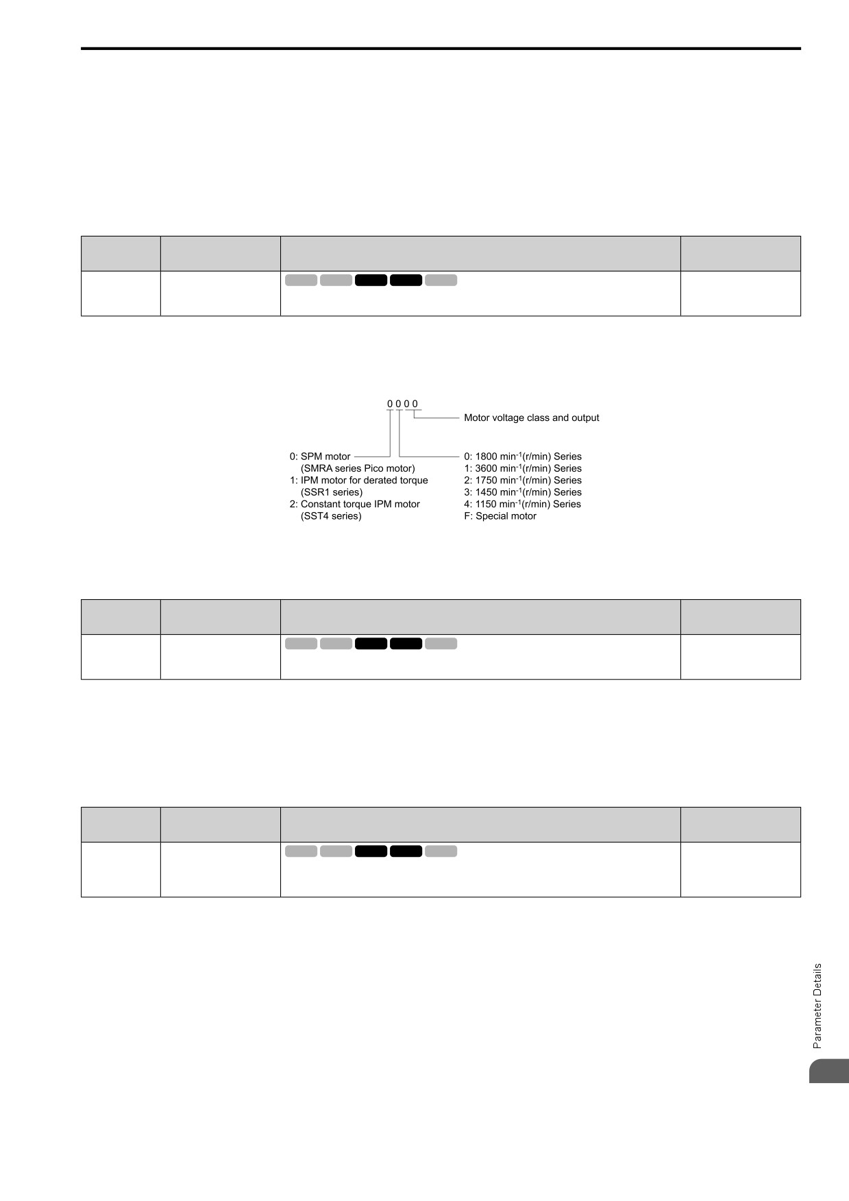
Set E5-01 to the motor code when using PM motors recommended by the manufacturer. E5 and other related
motor parameters will be automatically set to the optimal values.
Perform Auto-Tuning for all other PM motors. If information from motor nameplates or test reports is available,
the E5 parameters can be manually entered.
Note:
• The keypad shows E5-xx only when A1-02 = 5, 6 [Control Method = PM OLVector, PM AOLVector].
• E5-xx parameters are not reset when the drive is initialized using parameter A1-03 [Init Parameters].
■ E5-01: PM Mot Code Selection
No.
Default
Name
Description
(Hex.)
(Range)
E5-01
PM Mot Code Selection
V/f
OLV OLV/PM AOLV/PM EZOLV
FFFF
(0329)
Sets the motor code for Yaskawa PM motors. The drive uses the motor code to automatically set
(0000 - FFFF)
some parameters to their correct settings.
Note:
• If the drive hunts or shows an alarm after you enter a motor code, use the keypad to enter the value shown on the nameplate to E5-xx.
• When you use a PM motor other than a Yaskawa SMRA, SSR1, or SST4 series, set E5-01 = FFFF.
Figure 12.62 gives information about the motor code setting digits.
Figure 12.62 PM Motor Code
■ E5-02: PM Mot Rated Power (kW)
No.
Default
Name
Description
(Hex.)
(Range)
V/f
OLV OLV/PM AOLV/PM EZOLV
E5-02
PM Mot Rated Power (kW)
Determined by o2-04, C6-
01
(032A)
Sets the PM motor rated output in the units from o1-58 [Mot Capacity Unit].
(0.10 - 30.00 kW)
These Auto-Tuning methods will automatically set this parameter:
• PM Motor Parameter Settings
• PM Stationary Auto-Tuning
• PM Rotational Auto-Tuning
■ E5-03: PM Mot Rated Current (FLA)
No.
Default
Name
Description
(Hex.)
(Range)
E5-03
PM Mot Rated Current
V/f
OLV OLV/PM AOLV/PM EZOLV
Determined by o2-04, C6-
(FLA)
01
(032B)
Sets the PM motor rated current (FLA).
(10% to 200% of the drive
rated current)
Note:
When the drive model changes, the display units for this parameter also change.
• 0.01 A: 2001 to 2042, B001 to B018, 4001 to 4023
• 0.1 A: 2056 to 2082, 4031 to 4060
The drive automatically sets E5-03 to the value input for T2-06 [PMMot Rated Current] after you do these types
of Auto-Tuning:
• PM Motor Parameter Settings
• PM Stationary Auto-Tuning
• PM StaTun for Stator Resistance
12
• PM Rotational Auto-Tuning
539
12.5 E: MOTOR
■ E5-04: PM Mot Pole Count
No.
Default
Name
Description
(Hex.)
(Range)
E5-04
PM Mot Pole Count
V/f
OLV OLV/PM AOLV/PM EZOLV
4
(032C)
Sets the number of PM motor poles.
(2 - 120)
Note:
When A1-02 = 5, 6 or 8 [PM OLVector, PM AOLVector or EZ Vector], the maximum value is 48.
These types of Auto-Tuning will automatically set this parameter to the value of [Number of Motor Poles]:
• PM Motor Parameter Settings
• PM Stationary Auto-Tuning
• PM Rotational Auto-Tuning
■ E5-05: PM Mot Resistance (Ohms/Phase)
No.
Default
Name
Description
(Hex.)
(Range)
E5-05
PM Mot Resistance (Ohms/
V/f
OLV OLV/PM AOLV/PM EZOLV
0.100 Ω
Phase)
(032D)
Sets the resistance per phase of a PM motor. Set 50% of the line-to-line resistance.
(0.000 - 65.000 Ω)
PM motor Auto-Tuning automatically sets this parameter to the value of [PM Motor Stator Resistance].
Note:
Do not change the setting calculated by Auto-Tuning unless it is necessary.
■ E5-06: PM d-Axis Inductance (mH/Phase)
No.
Default
Name
Description
(Hex.)
(Range)
V/f
OLV OLV/PM AOLV/PM EZOLV
E5-06
PM d-Axis Inductance
1.00 mH
(032E)
(mH/Phase)
Sets the PM motor d-axis inductance.
(0.00 - 300.00 mH)
PM motor Auto-Tuning automatically sets this parameter to the value of [PM Motor d-Axis Inductance].
Note:
Do not change the setting calculated by Auto-Tuning unless it is necessary.
■ E5-07: PM q-Axis Inductance (mH/Phase)
No.
Default
Name
Description
(Hex.)
(Range)
E5-07
PM q-Axis Inductance
V/f
OLV OLV/PM AOLV/PM EZOLV
1.00 mH
(mH/Phase)
(032F)
Sets the PM motor q-axis inductance.
(0.00 - 600.00 mH)
PM motor Auto-Tuning automatically sets this parameter to the value of [PM Motor q-Axis Inductance].
Note:
Do not change the setting calculated by Auto-Tuning unless it is necessary.
■ E5-09: PM BackEMF Vpeak (mV/(rad/ s))
No.
Default
Name
Description
(Hex.)
(Range)
E5-09
PM BackEMF Vpeak (mV/
V/f
OLV OLV/PM AOLV/PM EZOLV
0.0 mV/(rad/sec)
(rad/ s))
(0331)
Sets the peak value of PM motor induced voltage.
(0.0 - 2000.0 mV/(rad/s))
Set this parameter when you use an IPM motor (SSR1-Series).
PM motor Auto-Tuning automatically sets this parameter to the value of [Back-EMF Voltage Constant (Ke)].
When E5-01 = FFFF, only set E5-09 or E5-24 [PM BackEMF L-L Vrms (mV/rpm)] as the induced voltage
constant.
Note:
When you set this parameter, also set E5-24 = 0.0. The drive will detect oPE08 [Parameter Selection Error] in these conditions:
• E5-09 = 0.0 and E5-24 = 0.0
• E5-09 ≠ 0.0 and E5-24 ≠ 0.0
540
12.5 E: MOTOR
■ E5-24: PM BackEMF L-L Vrms (mV/rpm)
No.
Default
Name
Description
(Hex.)
(Range)
E5-24
PM BackEMF L-L Vrms
V/f
OLV OLV/PM AOLV/PM EZOLV
200 V class: 100.0 mV/min-
1
(mV/rpm)
(0353)
Sets the RMS value for PM motor line voltage.
400 V class: 200.0 mV/min-
1
(0.0 - 6500.0 mV/min-1)
Set this parameter when you use an SPM motor (SMRD-series, SMRA-Series Pico motor).
PM motor Auto-Tuning automatically sets this parameter to the value of [Back-EMF Voltage Constant (Ke)].
When E5-01 = FFFF, only set E5-09 [PM BackEMF Vpeak (mV/(rad/ s))] or E5-24 as the induced voltage
constant.
Note:
When you set this parameter, also set E5-09 = 0.0. The drive will detect oPE08 [Parameter Selection Error] in these conditions:
• E5-09 = 0.0 and E5-24 = 0.0
• E5-09 ≠ 0.0 and E5-24 ≠ 0.0
■ E5-25: Polar Est Timeout
No.
Default
Name
Description
(Hex.)
(Range)
E5-25
Polar Est Timeout
V/f
OLV OLV/PM AOLV/PM EZOLV
0
(035E)
Sets the function that switches polarity for initial polarity estimation. Usually it is not necessary to
(0, 1)
change this setting.
Expert
When “Sd = 1” is shown on the motor nameplate or test report for Yaskawa motors, set this parameter to 1.
0 : Disabled
1 : Enabled
◆ E9: SIMPLE VECTOR SETTINGS
E9 parameters are used to configure induction motors, PM motors, and SynRM motors. Configure these
parameters only for derating torque applications in which a high level of responsiveness and accurate speed
control are not required.
E9 parameters are automatically configured with values input by the Auto-Tuning process for motor parameter
settings. E9 parameters can be manually configured when the EZ Tuning process cannot be performed.
■ E9-01: Motor Type Selection
No.
Default
Name
Description
(Hex.)
(Range)
E9-01
Motor Type Selection
V/f
OLV OLV/PM AOLV/PM EZOLV
0
(11E4)
Sets the type of motor.
(0 to 2)
EZ Tuning automatically sets this parameter to the value of [Motor Type Selection].
0 : IM
1 : PM
2 : SynRM
■ E9-02: Maximum Speed
No.
Default
Name
Description
(Hex.)
(Range)
E9-02
Maximum Speed
V/f
OLV OLV/PM AOLV/PM EZOLV
Determined by E9-01
(11E5)
Sets the maximum speed of the motor.
(40.0 - 120.0 Hz)
Note:
The unit of measure changes when the setting of o1-04 [V/f Pattern Unit for Display].
EZ Tuning automatically sets this parameter to the value of [Motor Max Revolutions].
12
541
12.5 E: MOTOR
■ E9-03: Rated Speed
No.
Default
Name
Description
(Hex.)
(Range)
E9-03
Rated Speed
V/f
OLV OLV/PM AOLV/PM EZOLV
Determined by E9-01
(11E6)
Sets the rated rotation speed of the motor.
(100 - 7200 min-1)
EZ Tuning automatically sets this parameter to the value of [Rated Speed].
Note:
Set E9-01 = 0 [Motor Type Selection = IM] before you set this parameter.
■ E9-04: Base Frequency
No.
Default
Name
Description
(Hex.)
(Range)
E9-04
Base Frequency
V/f
OLV OLV/PM AOLV/PM EZOLV
Determined by E9-01
(11E7)
Sets the rated frequency of the motor.
(40.0 - 120.0 Hz)
Note:
The unit of measure changes when the setting of o1-04 [V/f Pattern Unit for Display].
EZ Tuning automatically sets this parameter to the value of [Base Frequency].
■ E9-05: Base Voltage
No.
Default
Name
Description
(Hex.)
(Range)
V/f
OLV OLV/PM AOLV/PM EZOLV
E9-05
Base Voltage
200 V Class: 200.0 V, 400
(11E8)
Sets the rated voltage of the motor.
V: 400.0 V
(200 V Class: 0.0 - 255.0
V,400 V Class: 0.0 - 510.0
V)
EZ Tuning automatically sets this parameter to the value of [Base Voltage].
■ E9-06: Motor Rated Current
No.
Default
Name
Description
(Hex.)
(Range)
E9-06
Motor Rated Current
V/f
OLV OLV/PM AOLV/PM EZOLV
Determined by E9-01 and
o2-04
(11E9)
Sets the motor rated current in amps.
(10% to 200% of the drive
rated current)
Note:
When the drive model changes, the display units for this parameter also change.
• 0.01 A: 2001 to 2042, B001 to B018, 4001 to 4023
• 0.1 A: 2056 to 2082, 4031 to 4060
The setting value of E9-06 is the reference value for motor protection. Enter the motor rated current written on the
motor nameplate. Auto-Tuning the drive will automatically set E9-06 to the value input for T4-07 [Motor Rated
Current].
■ E9-07: Motor Rated Power (kW)
No.
Default
Name
Description
(Hex.)
(Range)
E9-07
Motor Rated Power (kW)
V/f
OLV OLV/PM AOLV/PM EZOLV
Determined by E9-02 and
o2-04
(11EA)
Sets the motor rated output in the units from o1-58 [Mot Capacity Unit].
(0.00 - 650.00 kW)
Auto-Tuning automatically sets this parameter to the value of [Motor Rated Power (kW)].
■ E9-08: Motor Pole Count
No.
Default
Name
Description
(Hex.)
(Range)
E9-08
Motor Pole Count
V/f
OLV OLV/PM AOLV/PM EZOLV
4
(11EB)
Sets the number of motor poles.
(2 to 120)
Auto-Tuning automatically sets this parameter to the value of [Number of Motor Poles].
542
12.5 E: MOTOR
■ E9-09: Motor Rated Slip
No.
Default
Name
Description
(Hex.)
(Range)
E9-09
Motor Rated Slip
V/f
OLV OLV/PM AOLV/PM EZOLV
0.000 Hz
(11EC)
Sets the motor rated slip.
(0.000 - 20.000 Hz)
The setting value of this parameter is the slip compensation reference value.
The drive uses the setting values of E9-03, E9-04, and E9-08 to calculate this parameter. When Motor Rated Slip
= 0, Auto-Tuning automatically sets this parameter to the value of [Motor Rated Slip].
Note:
Set E9-01 = 0 [Motor Type Selection = IM] before you set this parameter.
■ E9-10: Motor L-L Resistance
No.
Default
Name
Description
(Hex.)
(Range)
E9-10
Motor L-L Resistance
V/f
OLV OLV/PM AOLV/PM EZOLV
Determined by o2-04
(11ED)
Sets the line-to-line resistance for the motor stator windings.
(0.000 - 65.000 Ω)
Note:
This value is the motor line-to-line resistance. Do not set this parameter with the single-phase resistance.
Stationary Auto-Tuning automatically sets this parameter. If you cannot do Stationary Auto-Tuning, use the test
report from the motor manufacturer. You can calculate the motor line-to-line resistance with one of these
formulas:
• E-type insulation: the resistance value (Ω) shown on the test report at 75 °C × 0.92
• B-type insulation: the resistance value (Ω) shown on the test report at 75 °C × 0.92
• F-type insulation: the resistance value (Ω) shown on the test report at 115 °C × 0.87
12
543
12.6 F: OPTIONS
12.6
F: OPTIONS
F parameters are used to set option cards, which function as interfaces for encoders, analog I/O, digital I/O, and
fieldbus communication.
◆ F1: ENCODER
F1 parameters set the fault detection function in Speed Feedback (V/F Control). When A1-02 = 0 [Control
Method = V/f Control], set H6-01 = 3 [PI Pulse Train Function = PG Feedback] to enable this function. For
speed feedback, connect the single-channel pulse signal from the PG encoder to pulse train input terminal PI. Use
the Slip Compensation signal to improve the accuracy of Speed Control. This function is available for Motor 1.
WARNING! Sudden Movement Hazard. Do test runs and examine the drive to make sure that the command references are
correct. If you set the command reference incorrectly, it can cause damage to the drive or serious injury or death.
WARNING! Sudden Movement Hazard. Make sure that the host controller circuitry has correct safety design that will let you
keep control of the motor if the drive loses speed feedback. If you do not have control of the motor, it can cause serious injury or
death.
■ F1-02: PGOpen Detection Select
No.
Default
Name
Description
(Hex.)
(Range)
F1-02
PGOpen Detection Select
V/f
OLV OLV/PM AOLV/PM EZOLV
1
(0381)
Sets the method to stop the motor or let the motor continue operating when the drive detects PGo
(0 - 4)
[Encoder (PG) Feedback Loss].
If the drive does not detect ouput pulses from the encoder for the time set in F1-14 [Enc PGOpen Time for
Detection], it will trigger PGo.
Note:
• When A1-02 = 0 [Control Method = V/f Control], set H6-01 = 3 [PI Pulse Train Function = PG Feedback] to enable this parameter.
• Motor speed and load conditions can cause ov [Overvoltage] and oC [Overcurrent] faults.
0 : Ramp->Stop
The drive ramps the motor to stop in the deceleration time. The output terminal set for Fault [H2-01 to H2-03 =
E] activates.
1 : Coast->Stop
The output turns off and the motor coasts to stop. The output terminal set for Fault [H2-01 to H2-03 = E]
activates.
2 : Fast Stop (C1-09)
The drive stops the motor in the deceleration time set in C1-09 [Fast Stop Time]. The output terminal set for Fault
[H2-01 to H2-03 = E] activates.
3 : Alarm Only
The keypad shows PGo and the drive continues operation. Only use this setting in special conditions to prevent
damage to the motor and machinery. The output terminal set to Alarm [H2-01 to H2-03 = 4] activates.
4 : No Alarm Display
The drive continues operation and does not show PGo on the keypad. Only use this setting in special conditions to
prevent damage to the motor and machinery.
■ F1-03: Overspeed Detection Selection
No.
Default
Name
Description
(Hex.)
(Range)
F1-03
Overspeed Detection
V/f
OLV OLV/PM AOLV/PM EZOLV
1
Selection
(0382)
Sets the method to stop the motor or let the motor continue to operate when the drive detects oS
(0 - 3)
[Overspeed].
When the motor speed is more than the value set in F1-08 [Overspeed Level] for longer than the time set in F1-09
[Overspeed Delay Time] it will trigger oS.
0 : Ramp->Stop
The drive ramps the motor to stop in the deceleration time. The output terminal set for Fault [H2-01 to H2-03 =
3] activates.
1 : Coast->Stop
544
12.6 F: OPTIONS
The output turns off and the motor coasts to stop. The output terminal set for Fault [H2-01 to H2-03 = 3]
activates.
2 : Fast Stop (C1-09)
The drive stops the motor in the deceleration time set in C1-09 [Fast Stop Time]. The output terminal set for Fault
[H2-01 to H2-03 = 3] activates.
3 : Alarm Only
The keypad shows oS and the drive continues operation. Only use this setting in special conditions to prevent
damage to the motor and machinery. The output terminal set to Alarm [H2-01 to H2-03 = 4] activates.
Note:
• When A1-02 = 0 [Control Method = V/f Control], set H6-01 = 3 [PI Pulse Train Function = PG Feedback] to enable this parameter.
• When A1-02 = 6 [Control Method = PM AOLVector], the drive will automatically set F1-03 = 1 [Coast->Stop]. You cannot change
this value.
■ F1-04: Speed Dev Detection Select
No.
Default
Name
Description
(Hex.)
(Range)
F1-04
Speed Dev Detection Select
V/f
OLV OLV/PM AOLV/PM EZOLV
3
(0383)
Sets the method to stop the motor or let the motor continue to operate when the drive detects dEv
(0 - 3)
[Speed Deviation].
When the difference between the frequency reference and the motor speed is more than the value set in F1-10
[Speed Dev Level] for longer than the time set in F1-11 [Speed Dev Delay Time], it will trigger dEv.
Note:
When A1-02 = 0 [Control Method = V/f Control], set H6-01 = 3 [PI Pulse Train Function = PG Feedback] to enable this parameter.
0 : Ramp->Stop
The drive ramps the motor to stop in the deceleration time. The output terminal set for Fault [H2-01 to H2-03 =
3] activates.
1 : Coast->Stop
The output turns off and the motor coasts to stop. The output terminal set for Fault [H2-01 to H2-03 = 3]
activates.
2 : Fast Stop (C1-09)
The drive stops the motor in the deceleration time set in C1-09 [Fast Stop Time]. The output terminal set for Fault
[H2-01 to H2-03 = 3] activates.
3 : Alarm Only
The keypad shows dEv and the drive continues operation. Only use this setting in special conditions to prevent
damage to the motor and machinery. The output terminal set to Alarm [H2-01 to H2-03 = 4] activates.
■ F1-08: Overspeed Level
No.
Default
Name
Description
(Hex.)
(Range)
F1-08
Overspeed Level
V/f
OLV OLV/PM AOLV/PM EZOLV
115%
(0387)
Sets the detection level of oS [Overspeed] as a percentage when the maximum output frequency
(0 - 120%)
is 100%.
When the motor speed is more than the value set in F1-08 for longer than the time set in F1-09 [Overspeed Delay
Time], the drive will detect oS.
Note:
When A1-02 = 0 [Control Method = V/f Control], set H6-01 = 3 [PI Pulse Train Function = PG Feedback] to enable this parameter.
■ F1-09: Overspeed Delay Time
No.
Default
Name
Description
(Hex.)
(Range)
F1-09
Overspeed Delay Time
V/f
OLV OLV/PM AOLV/PM EZOLV
Determined by A1-02
(0388)
Sets the length of time that the speed feedback must be more than the F1-08 level to cause oS
(0.0 - 2.0 s)
[Overspeed].
When the motor speed is more than the value set in F1-08 [Overspeed Level] for longer than the time set in F1-
12
09, the drive will detect oS.
545
12.6 F: OPTIONS
Note:
When A1-02 = 0 [Control Method = V/f Control], set H6-01 = 3 [PI Pulse Train Function = PG Feedback] to enable this parameter.
■ F1-10: Speed Dev Level
No.
Default
Name
Description
(Hex.)
(Range)
F1-10
Speed Dev Level
V/f
OLV OLV/PM AOLV/PM EZOLV
10%
(0389)
Sets the detection level of dEv [Speed Deviation] as a percentage when the maximum output
(0 - 50%)
frequency is 100%.
When the speed deviation between the frequency reference and the actual motor speed is more than the value set
in F1-10 for longer than the time set in F1-11 [Speed Dev Delay Time], the drive will detect dEv.
Note:
When A1-02 = 0 [Control Method = V/f Control], set H6-01 = 3 [PI Pulse Train Function = PG Feedback] to enable this parameter.
■ F1-11: Speed Dev Delay Time
No.
Default
Name
Description
(Hex.)
(Range)
F1-11
Speed Dev Delay Time
V/f
OLV OLV/PM AOLV/PM EZOLV
0.5 s
(038A)
Sets the length of time that the difference between the frequency reference and speed feedback
(0.0 - 10.0 s)
must be more than the level in F1-10 to cause dEv [Speed Deviation].
When the speed deviation between the frequency reference and the actual motor speed is more than the value set
in F1-10 [Speed Dev Level] for longer than the time set in F1-11, the drive will detect dEv.
Note:
When A1-02 = 0 [Control Method = V/f Control], set H6-01 = 3 [PI Pulse Train Function = PG Feedback] to enable this parameter.
■ F1-14: Enc PGOpen Time for Detection
No.
Default
Name
Description
(Hex.)
(Range)
F1-14
Enc PGOpen Time for
V/f
OLV OLV/PM AOLV/PM EZOLV
2.0 s
Detection
(038D)
Sets the length of time that the drive must not receive a pulse signal to cause PGo [Encoder (PG)
(0.0 - 10.0 s)
Feedback Loss].
If the drive does not detect ouput pulses from the encoder for the time set in F1-14, it will trigger PGo.
Note:
• When A1-02 = 0 [Control Method = V/f Control], set H6-01 = 3 [PI Pulse Train Function = PG Feedback] to enable this parameter.
• Motor speed and load conditions can cause ov [Overvoltage] and oC [Overcurrent] faults.
◆ F6: COMMUNICATIONS, F7: ETHERNET
F6 and F7 parameters are used to set the basic communication settings and method of fault detection for the
communication option card. The communication option card parameters include common option card parameters
and communication protocol-specific parameters.
The following table lists the parameters that need to be set for each communication option card.
Refer to the technical manual for each communication option card for more information on installing, wiring, and
configuring the details needed before starting communication.
WARNING! Sudden Movement Hazard. Do test runs and examine the drive to make sure that the command references are
correct. If you set the command reference incorrectly, it can cause damage to the drive or serious injury or death.
Table 12.30 Correspondence Between Communication Protocols and Parameters (SI-C3, SI-T3, SI-ET3, SI-P3, SI-S3,
and SI-ES3)
CC-Link
MECHATROLINK-II
MECHATROLINK-III
PROFIBUS-DP
CANopen
EtherCAT
Parameter
SI-C3
SI-T3
SI-ET3
SI-P3
SI-S3
SI-ES3
F6-01 to F6-03
x
x
x
x
x
x
F6-04
x
-
-
-
-
-
F6-06 to F6-08
x
x
x
x
x
x
F6-10, F6-11
x
-
-
-
-
-
F6-14
x
x
x
x
x
x
F6-16
x
x
x
x
x
x
546
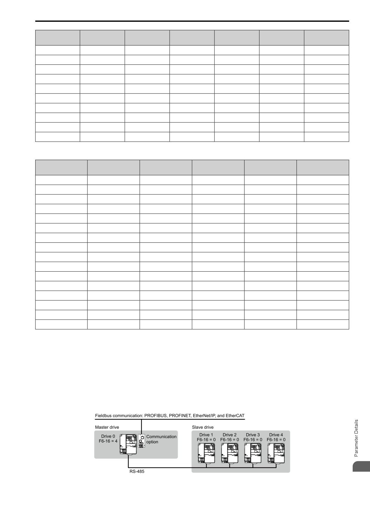
12.6 F: OPTIONS
CC-Link
MECHATROLINK-II
MECHATROLINK-III
PROFIBUS-DP
CANopen
EtherCAT
Parameter
SI-C3
SI-T3
SI-ET3
SI-P3
SI-S3
SI-ES3
F6-20, F6-21
-
x
x
-
-
-
F6-22
-
x
-
-
-
-
F6-23 to F6-26
-
x
x
-
-
-
F6-30 to F6-32
-
-
-
x
-
-
F6-35, F6-36
-
-
-
-
x
-
F6-50 to F6-71
-
-
-
-
-
-
F7-01 to F7-15
-
-
-
-
-
-
F7-16
-
-
-
-
-
-
F7-17 to F7-42
-
-
-
-
-
-
F7-60 to F7-79
-
-
-
x
-
-
Table 12.31 Relation Between Communication Protocols and Parameters (SI-B3, SI-N3, SI-W3, SI-EM3, SI-EP3, and SI-
EN3)
DeviceNet
LonWorks
Modbus TCP/IP
PROFINET
EtherNet/IP
Parameter
SI-N3
SI-W3
SI-EM3
SI-EP3
SI-EN3
F6-01 to F6-03
x
x
x
x
x
F6-04
-
-
-
-
-
F6-06 to F6-08
x
x
x
x
x
F6-10, F6-11
-
-
-
-
-
F6-14
x
x
x
x
x
F6-16
x
x
x
x
x
F6-20, F6-21
-
-
-
-
-
F6-22
-
-
-
-
-
F6-23 to F6-26
-
-
-
-
-
F6-30 to F6-32
-
-
-
-
-
F6-35, F6-36
-
-
-
-
-
F6-50 to F6-71
x
-
-
-
-
F7-01 to F7-15
-
-
x
x
x
F7-16
-
-
x
-
-
F7-17 to F7-42
-
-
-
x
x
F7-60 to F7-79
-
-
-
-
-
■ Gateway Mode
Note:
When you use Gateway Mode, do not install the communication option in slave drives. If you install a communication option in a slave
drive, the drive commands and responses will not synchronize.
In gateway mode, you can use one communication option to communicate with more than one drive.
You can use one communication option to connect a maximum of five drives to the field bus communications.
Refer to Figure 12.63 for more information.
When you install a communication option on the master drive, you can use the RS-485 communication card to
transmit data to slave drives that do not have a communication option.
12
Figure 12.63 Connection Examples in Gateway Mode
547
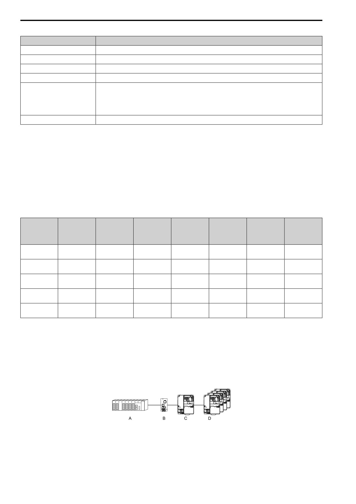
12.6 F: OPTIONS
Table 12.32 Specification
Item
Specification
Applicable options
All options that support the Modbus access function (for example, PROFIBUS-DP, PROFINET, EtherNet/IP, EtherCAT)
Compatible Products
Drives that can set F6-16 [Gateway Mode] *1
Number of connected drives
Maximum: 5 units
Communication specifications
Modbus (RTUmode) communications
Commands/responses
The controller can send this data to each drive (Drive 0 to Drive 4):
• Control commands: Run commands and frequency references
• Control responses: Output frequency and drive status (during run, faults)
• Read and write parameters
• Read monitors
Synchronous control
Not supported
*1
Gateway Mode is not available with Yaskawa 1000-series drives or previous series drives.
Note:
• The communication speed in gateway mode is slower than the speed in fieldbus communications. Make sure that the speed is
acceptable for your system.
• Response speed with the communication option is slower than with point-to-point communications.
• Set H5-03 [Mbus Parity] to the same value on the master drive and slave drives.
WARNING! Injury to Personnel. Separately prepare safety protection equipment and systems, for example fast stop switches. If
the motor does not stop correctly from the disconnection of communications cable or electrical interference, it can cause serious
injury.
Configuring Gateway Mode
The following table shows sample settings to connect 4 slave drives:
Table 12.33 Sample Settings for Using Gateway Mode
H5-02
H5-01
H5-06
H5-09
b1-02
F6-16
[Mbus BaudRate]
b1-01
[Mbus Address]
[Mbus Tx Wait
[Mbus CE Detect
[Run Comm. Sel
[Gateway Mode]
H5-03
[Freq. Ref. Sel. 1]
*1
Time]
Time]
1]
[Mbus Parity]
Drive 0
5 ms (factory
1 - 4 *2
1F (Default)
*5
≥ 2.0 s *7
3 [Option PCB]
3 [Option PCB]
(Master Drive)
default) *6
Drive 1
5 ms (factory
0
01 *3 *4
*5
≥ 0.9 s *7
2 [Modbus] *8
2 [Modbus] *8
(Slave drive)
default) *6
Drive 2
5 ms (factory
0
02 *3 *4
*5
≥ 0.9 s *7
2 [Modbus] *8
2 [Modbus] *8
(Slave drive)
default) *6
Drive 3
5 ms (factory
0
03 *3 *4
*5
≥ 0.9 s *7
2 [Modbus] *8
2 [Modbus] *8
(Slave drive)
default) *6
Drive 4
5 ms (factory
0
04 *3 *4
*5
≥ 0.9 s *7
2 [Modbus] *8
2 [Modbus] *8
(Slave drive)
default) *6
*1
Restart the drive to apply the new settings.
*2
Specify the number of slave drives you will connect.
*3
Setting 0 will not let the drive respond to Modbus communications.
*4
Set a slave address that is different from other slave devices.
*5
Enter the same value that you use for the master drive.
*6
To correctly detect the response timeout, do not change the value of H5-06 from the default value.
*7
Set H5-09 ≥ 0.9. When H5-09 < 0.9, the drive will detect CE [Modbus Communication Error] before it detects a response timeout.
*8
On each slave drive, set b1-01 [Freq. Ref. Sel. 1] and b1-02 [Run Comm. Sel 1] to 2 [Modbus].
An Overview of Gateway Mode
When in gateway mode, the drive will operate as shown in Table 12.34.
A - Controller
C - Master Drive (Drive 0)
B - Communication Option
D - Slave Drives (Drives 1 to 4)
548
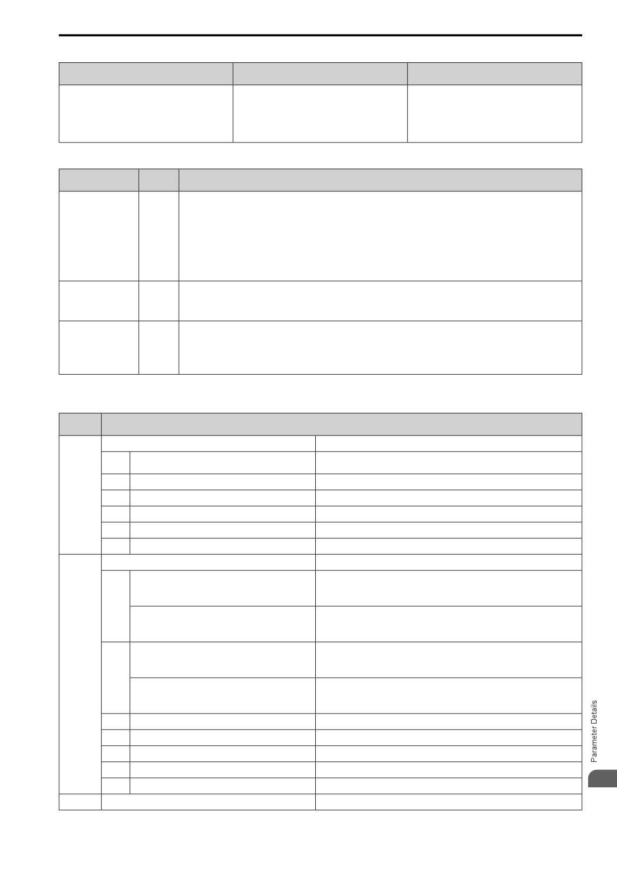
12.6 F: OPTIONS
Table 12.34 Operation in Gateway Mode
Master Drive (Drive 0) to Slave Drives (Drives 1 to
Controller to Communication Option
Communication Option to Master Drive (Drive 0)
4)
• The controller and card communicate in the format of
Field bus communication data is written to and read from
• Uses Modbus communications.
each field bus communications protocol.
the special registers of Drive 0.
• Drive 0 sends data from its special registers to Drives
• Drive 0 sends commands and monitors through normal
1 to 4.
field bus communications.
• The special registers of Drive 0 use read and write to
send commands to and monitor Drives 1 to 4.
Operations at the Time of Communication Error
Error
Communication Error
Operation
Codes
• Master drive
Detects bUS [Option Communication Error] and operates as specified by F6-01 [Comm.Error Selection].
• Slave drive
Detects CE [Modbus Communication Error] and operates as specified by H5-04 [Mbus Error Stop].
From controller to
Note:
bUS
communication option
• After error detection, each drive can continue the operation specified by the last received command if the F6-01 and H5-04 settings
agree. Because the controller cannot stop the operation, you must supply a stopping method, for example an emergency stop
switch.
• If you set H5-05 = 0 [Mbus Fault Detection Selection = Disabled], the drive will not detect CE. The H5-04 setting does not have
an effect.
• Master drive
From communication
Detects oFAxx and coasts to stop.
option to master drive
oFAxx
• Slave drive
Detects hLCE [High Level Communication Errors] and coasts to stop.
The master drive stops communicating with the slave drive in these conditions: Reset the fault to restart communication.
The slave drive detects CE after H5-09 [Mbus CE Detect Time] is expired. Then it operates in as specified with H5-04 [Mbus Error
From master drive to
Stop].
CE
slave drive
• A message error occurred in the send data from the slave drive 10 consecutive times.
• Response from the slave drive timed out 10 consecutive times.
Gateway Special Register Specification
Table
12.35
Command Data
Register
Description
No. (Hex.)
Command source update
This flag enables command updates.
To input the Run command and frequency reference at the same time, write all
bit 0
Drive 1 Update Command Enabled
commands, then change the bit value from 0 to 1.
bit 1
Drive 2 Update Command Enabled
15C5
bit 2
Drive 3 Update Command Enabled
bit 3
Drive 4 Update Command Enabled
bit 4
Update Register Access Command Enabled
bit 5 - F
Reserved
Run Command (Drive 1)
H5-12 = 0: FWD/Stop
0 = Stop
1 = Forward run
bit 0
H5-12 = 1: Run/Stop
0 = Stop
1 = Run
H5-12 = 0: REV/Stop
0 = Stop
1 = Reverse run
15C6
bit 1
H5-12 = 1: FWD/REV
0 = Forward run
1 = Reverse run
bit 2
External fault
bit 3
Fault Reset
bit 4
ComRef
bit 5
ComCtrl
12
bit 6 - F
Reserved
15C7
Frequency Reference (Drive 1)
The unit of measure changes when o1-03 changes.
549