Q2V Driving Quality. Technical Manual (Item code: Q2V-Axxxx-xxx, 2020) - page 12
12.1 A: INITIALIZATION
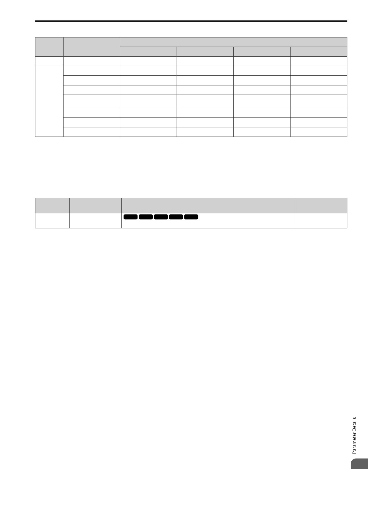
Table 12.1 Access Level and Available Keypad Screens
A1-01 [Access Level] Setting
Mode
Keypad Screen
0
1
2
3
Drive Mode
Monitors
Yes
Yes
Yes
Yes
Parameters
Yes
Yes
Yes
Yes
Manual Setup
No
Yes
Yes
Yes
Parameter Backup/Restore
No
No
Yes
Yes
Programming
Modified Parameters/Fault
No
No
Yes
Yes
Mode
Log
Auto-Tuning
No
No
Yes
Yes
Initial Setup Screen
No
No
Yes
Yes
Diagnostic Tools
No
No
Yes
Yes
Note:
• When you use A1-04 and A1-05 [Password Setting] to set a password, you cannot change the values set in A1-01 to A1-03, A1-07,or
A2-01 to A2-32.
• When H1-xx = 7C [MFDI Function Select = Prg Lock], you must activate the terminal to change parameter settings.
• When you use Modbus communications, you must send the Enter command from the controller to the drive and complete the serial
communication write process before you can use the keypad to change parameter settings.
■ A1-02: Control Method
No.
Default
Name
Description
(Hex.)
(Range)
A1-02
Control Method
V/f
OLV OLV/PM AOLV/PM EZOLV
0
(0102)
Sets the control method for the drive application and the motor.
(0, 2, 5, 6, 8)
Note:
When you change the A1-02 setting, the parameter values specified by A1-02 are changed to their default values.
Sets the control method for the drive application and the motor.
0 : V/f Control
Use this control method in these applications and conditions:
• For general variable-speed control applications in which a high level of responsiveness or high-precision speed
control is not necessary.
• To connect more than one motor to one drive
• When there is not sufficient data to set the motor parameters
• When it is not possible to do Auto-Tuning. The speed control range is 1:40.
2 : OLVector
Use this control method for general variable-speed control applications in which high-precision speed control is
necessary. In this control method, a feedback signal from the motor is not necessary to have high torque response
and high torque when operating at low speeds. The speed control range is 1:120.
5 : PM OLVector
The drive controls an IPM motor or SPM motor in this control method. Use this control method for general
variable-speed control applications in which a high level of responsiveness or high-precision speed control are not
necessary. The speed control range is 1:20.
6 : PM AOLVector
The drive can control an IPM motor in this control method. Use this control method for general variable-speed
control applications in which high-precision speed control and torque limit are necessary. The speed control range
is 1:20. The speed control range is 1:100 when n8-57 = 1 [High-Freq Injection = Enabled].
8 : EZ Vector
The drive controls induction motors and PM motors in this control method. This control method uses an easier
procedure to operate motors with more efficiency. Use this control method for derating torque applications. For
example, fans and pumps.
12
433
12.1 A: INITIALIZATION
■ A1-03: Init Parameters
No.
Default
Name
Description
(Hex.)
(Range)
A1-03
Init Parameters
V/f
OLV OLV/PM AOLV/PM EZOLV
0
(0103)
Sets parameters to default values.
(0 - 3330)
Note:
• After you initialize the drive, the drive automatically sets A1-03 = 0.
• User Parameters can save the parameter values for your application and use these values as default values for drive initialization.
• To use the 2 motor switchover function, first turn OFF the terminal to which H1-xx = 61 [MFDI Function Select = A1-03: Motor 2
Select] is set, then change the A1-03 setting. An incorrect procedure will trigger oPE08 [Parameter Selection Error].
0 : No Initialization
1110 : User / Solution Initialization
Sets parameters to the values set by the user as user settings. Set o2-03 = 1 [UserPar Set Default Values = Set
defaults] to save the user settings.
You can save the parameter settings that were adjusted for the test run as user-set default values to the drive.
When you make changes to the parameter values after you save the settings as User Parameter Settings, the drive
will set the parameters to the User Parameter Setting value when you initialize with A1-03 = 1110.
Follow this procedure to save User Parameter setting values, and to do a User Initialization.
1. Set parameters correctly for the application.
2. Set o2-03 = 1 [UserPar Set Default Values = Set defaults].
This saves parameter settings for a User Initialization.
The drive will then automatically set o2-03 = 0.
3. Set A1-03 = 1110 to reset to the saved parameter settings.
When you initialize the drive, the drive sets the parameter values to the User Parameter setting values.
2220 : 2-Wire Initialization
Sets MFDI terminal DI1 to Forward Run and terminal DI2 to Reverse Run, and resets all parameters to default
settings.
3330 : 3-Wire Initialization
Sets MFDI terminal DI1 to Run, terminal DI2 to Stop, and terminal DI5 to FWD/REV, and resets all parameters to
default settings.
The drive will not initialize the parameters in Table 12.2 when A1-03 = 2220, 3330.
Table 12.2 Parameters that are not Initialized Using a 2-Wire Sequence or a 3-Wire Sequence
No.
Name
No.
Name
A1-00
Language Selection
E5-09
PM BackEMF Vpeak (mV/(rad/ s))
A1-02
Control Method
E5-24
PM BackEMF L-L Vrms (mV/rpm)
A1-07
Q2pack Enable
E5-25
Polar Est Timeout
E1-03
V/f Pattern Selection
F6-08
Comm Par RST@Initialize
E5-01
PM Mot Code Selection
F6-xx/F7-xx
Communication Option Parameters
Set F6-08 = 1 [Comm Par RST@Initialize = Factory
E5-02
PM Mot Rated Power (kW)
Default - Reset] to initialize communication option
parameters.
E5-03
PM Mot Rated Current (FLA)
L8-35
Installation Selection
E5-04
PM Mot Pole Count
o2-04
Drive KVA Selection
E5-05
PM Mot Resistance (Ohms/Phase)
q1-xx - q8-xx
q1-01 to q8-40: Q2pack Parameters
E5-06
PM d-Axis Inductance (mH/Phase)
r1-xx
r1: Q2PACK JOINTS
E5-07
PM q-Axis Inductance (mH/Phase)
Note:
• When A1-03 = 2220, 3330, the drive automatically set A1-05 [Password Setting] = 0000. Make sure that you set the password again
for applications where a password is necessary.
434
12.1 A: INITIALIZATION
■ A1-04: Password Input
No.
Default
Name
Description
(Hex.)
(Range)
A1-04
Password Input
V/f
OLV OLV/PM AOLV/PM EZOLV
0000
(0104)
Entry point for the password set in A1-05 [Password Setting]. The user can view the settings of
(0000 - 9999)
parameters that are locked without entering the password. Enter the correct password in this
parameter to change parameter settings.
If the password entered in A1-04 does not agree with the password setting in A1-05, you cannot change these
parameters:
• A1-01 [Access Level]
• A1-02 [Control Method]
• A1-03 [Init Parameters]
• A1-07 [Q2pack Enable]
• A2-01 to A2-32 [MAN1 Param1 to MAN3 Param12]
To lock parameter settings after making changes without changing the password, enter the incorrect password in
A1-04 and push
Enter the Password to Unlock Parameters
Use this procedure to unlock parameter settings.
Set the password in A1-05 [Password Setting], and show the Parameter Setting Mode screen on the keypad.
This procedure verifies the password, and makes sure that the parameter settings are unlocked.
1. Push
or
to select “A: Initialization Parameters”, then push
2. Push
or
to select [A1-04], then push
You can now change parameter settings.
3. Push
or
to move the digit and enter the password.
4. Push
to confirm the password.
The drive unlocks the parameters and automatically shows the Parameters Screen.
5. Push
or
to show [A1-02], then push
The keypad shows the setting value for [A1-02].
6. Push
or
to make sure that you can change the setting value.
Push
(Back) until the keypad shows the Parameter Setup Mode screen.
■ A1-05: Password Setting
No.
Default
Name
Description
(Hex.)
(Range)
A1-05
Password Setting
V/f
OLV OLV/PM AOLV/PM EZOLV
0000
(0105)
Set the password to lock parameters and prevent changes to parameter settings. Enter the correct
(0000 - 9999)
password in A1-04 [Password Input] to unlock parameters and accept changes.
This parameter can lock these parameter settings:
• A1-01 [Access Level]
• A1-02 [Control Method]
• A1-03 [Init Parameters]
• A1-07 [Q2pack Enable]
• A2-01 to A2-32 [MAN1 Param1 to MAN3 Param12]
12
435
12.1 A: INITIALIZATION
Note:
• Usually, the keypad will not show A1-05. To show and set A1-05, show A1-04 [Password Input] and then:
-If LCD keypad is used: Push
and
at the same time.
–If LED keypad is used: Push
and
at the same time.
• After you set A1-05, the keypad will not show it again until you enter the correct password in A1-04. Make sure that you remember the
A1-05 setting value. If you do not know the A1-05 setting value, contact the manufacturer or your nearest sales representative.
• When A1-03 = 2220, 3330 [2-Wire Initialization, 3-Wire Initialization], the drive is initialized to A1-05 = 0000. Be sure to set the
password again when a password is necessary for the application.
• Change the setting value in A1-05 to change the password. The new setting value becomes the new password.
• When you use the password to unlock and change a parameter, enter a value other than the password in A1-04 to lock the parameter
again with the same password.
• If A1-04 ≠ A1-05, Modbus Communication cannot read or write A1-05.
■ A1-07: Q2pack Enable
No.
Default
Name
Description
(Hex.)
(Range)
A1-07
Q2pack Enable
V/f
OLV OLV/PM AOLV/PM EZOLV
0
(0128)
Sets the drive to operate with Q2pack.
(0 - 2)
Q2pack is a simple visual programming tool that lets you connect function blocks to customize the drive and add
PLC functions.
Note:
• Q2pack will overwrite drive settings when it uses MFDI/MFDO and MFAI/MFAO. When you use Q2pack to make changes to the
drive, the changes will stay after you disable Q2pack.
• For more information about Q2pack, contact your nearest sales representative.
0 : Disable Q2pack
1 : Enable Q2pack
2 : With DI
Set H1-xx = 9F [MFDI Function Select = Q2pack Disable]. Deactivate the digital input to enable programs made
with Q2pack and activate the terminal to disable the programs.
■ A1-11: Firmware Update Lock
No.
Default
Name
Description
(Hex.)
(Range)
A1-11
Firmware Update Lock
V/f
OLV OLV/PM AOLV/PM EZOLV
0
(111D)
Protects the drive firmware. When you enable the protection, you cannot update the drive
(0, 1)
firmware.
Expert
0 : Disabled
Lock is disabled.
1 : Enabled
Lock is enabled.
■ A1-12: Bluetooth ID
No.
Default
Name
Description
(Hex.)
(Range)
A1-12
Bluetooth ID
V/f
OLV OLV/PM AOLV/PM EZOLV
-
(1564)
Sets the password necessary to use Bluetooth to control the drive with a smartphone or tablet.
(0000 - 9999)
◆ A2: MANUAL SELECTION
You can register frequently used parameters and recently changed parameters here to access them quickly. Use
Setup Mode to show the saved parameters.
436
12.1 A: INITIALIZATION
■ A2-01 to A2-32: MAN1 Param1 to MAN3 Param12
No.
Default
Name
Description
(Hex.)
(Range)
A2-01 to A2-32
MAN1 Param1 to MAN3
V/f
OLV OLV/PM AOLV/PM EZOLV
Parameters in General-
Param12
Purpose Setup Mode
(0106 - 0125)
You can select a maximum of 32 parameters for the drive and save the values to parameters A2-01
to A2-32. Use Setup Mode to show the saved parameters. You can immediately access these saved
(Determined by A1-07)
parameters.
Note:
• You must set A1-01 = 1 [Access Level = Manual Setup] to access parameters A2-01 to A2-32.
• When A1-07 = 1 or 2 [Q2pack Enable = Enable Q2pack or With DI], the drive saves qx-xx [q1-01 to q8-40: Q2pack Parameters] to
A2-01 to A2-32.
The drive saves these parameters to A2-01 to A2-32.
• The drive saves a maximum of 32 parameters.
Note:
Set A1-01 = 2 [Standard Parameters] or A1-01 = 3 [Expert Parameters] to save the necessary parameters.
• The drive automatically saves changed parameters to A2-17 to A2-32.
Note:
Set A2-33 = 1 [Manual Autoset Parameters = Auto Save].
■ A2-33: Manual Autoset Parameters
No.
Default
Name
Description
(Hex.)
(Range)
A2-33
Manual Autoset Parameters
V/f
OLV OLV/PM AOLV/PM EZOLV
0
(0126)
Sets the automatic save feature for changes to parameters A2-17 to A2-32 [MAN2 Param7 to
(0, 1)
MAN3 Param12].
0 : Manual Entry
Set User Parameters manually.
1 : Auto Save
The drive automatically registers changed parameter A2-17 to A2-32. The drive automatically saves the most
recently changed parameter to A2-17, and saves a maximum of 16 parameters. After the drive registers 16
parameters, when you save a new parameter, the drive will remove a parameter from the User Parameter list to
make space for the new parameter. The drive removes parameters with First In, First Out.
Use Setup Mode to show the saved parameters.
Note:
In General-Purpose Setup Mode, the drive saves parameters starting with A2-27 because the drive saves parameters A2-26 and lower by
default.
◆ Notes for Elevator Applications
When using the drive for elevator applications, read the safety descriptions and precautions, and safely and
correctly use the device.
■ Conditions to Open and Close the Brake
Set L4-07 = 1 [SpAgree Det.Selection = No Detect@BB] to open and close the holding brake.
When L4-07 = 2 [Always Detect], the output frequency increases when you input the Run command although the
external baseblock command is input. Because of this, speed detection operates and will open the brake signal.
• Set Related Parameters
This table shows examples of parameter settings to use the terminal DO2-O2C as the holding brake open and
close signal.
Table 12.3 Holding Brake Open and Close Signal Setting Example
Applicable Control Methods
Brake Open and Close Signal
Brake Open and Close Level Adjust
(A1-02 Settings)
V/f Control
OLVector
Signal Name
Parameter Settings
Signal Name
Parameter Settings
(0)
(2)
L4-07 = 0
SpAgree Det.Level
L4-01 = 1.0 Hz to 3.0 Hz *1
12
Frequency (FOUT) Detection 2
x
x
H2-03 = 5
SpAgree Det.Width
L4-02 = 0.0 Hz to 0.5 Hz
437
12.1 A: INITIALIZATION
*1
When A1-02 = 2 [OLVector], it is the usual setting range. When A1-02 = 0 [V/f Control], set L4-01 to the rated slip frequency of the
motor + approximately 0.5 Hz. If you set the value too low, motor torque will not be sufficient and it will cause motor rollback. Set
the parameter to agree with these conditions at the same time. If you set the value too high, it will cause overshoot at start.
• L4-01 > E1-09 [Min Output Frequency]
• L4-01 > L4-02 [Powloss Ramp Time@recovery]
*2
Use L4-02 to adjust the detection width of Frequency Detection 2. If rollback occurs when the motor stops, change the frequency to
approximately 0.1 Hz.
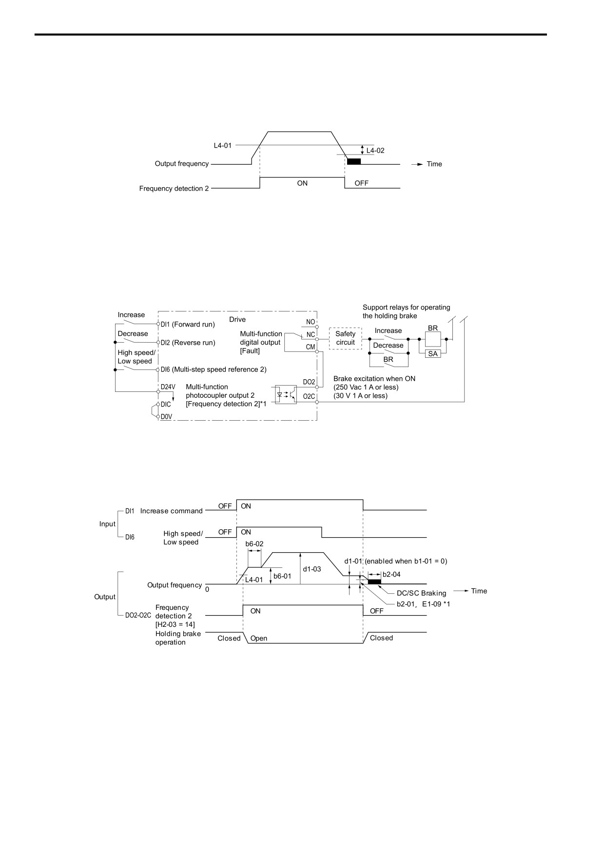
Figure 12.1 Frequency Detection 2
■ Sequence Circuit Configuration
Use these conditions to set the circuit for the open/close sequence of the holding brake:
• Set the sequence-side operation conditions to activate terminal DO2-O2C and open the holding brake.
• Set the sequence to close the holding brake in an emergency if the drive detects a fault.
• Set the sequence to open the holding brake when you enter an increase or decrease command.
Figure 12.2 Sequence Circuit Configuration Diagram
*1
L4-07 = 1 [SpAgree Det.Selection = No Detect@BB]
■ Time Chart
This figure shows the open and close sequence of the holding brake.
Figure 12.3 Holding Brake Open and Close Sequence Time Chart (V/f, OLV)
*1
Start braking from the higher set frequency between b2-01 [ZSpd/DCI Threshold] or E1-09 [Min Output Frequency].
438

12.1 A: INITIALIZATION
■ Notes on when Using Other Functions
Functions
Notes
Stall Prevention during Deceleration
When you connect a braking resistor to discharge the regenerative power to the drive, set L3-04 = 0 [StallP@Decel Enable =
Disabled].
Note:
If L3-04 = 1 [Enabled], it is possible that the drive will not stop in the set deceleration time. Do not change the default settings
of these related parameters:
• L3-01 = 2 [StallP Mode@Accel = General Purpose]
• L3-05 = 1 [StallP@RUN Enable = Enabled]
Auto-Tuning for Induction Motors
• When A1-02 = 2 [Control Method = OLVector], Auto-Tune the motor before you operate the drive.
• Disconnect the drive from the motor to do Rotational Auto-Tuning.
• Auto-Tuning runs automatically for approximately 1 minute. Do not do Auto-Tuning with the motor engaged in the elevator
system.
Note:
• If you cannot disconnect the motor from the machine, do Stationary Auto-Tuning. During this time, the drive automatically
measures the necessary motor data. If the motor test report or the motor nameplate is not available, use Stationary Auto-Tuning.
Do Stationary Auto-Tuning for Line-to-Line Resistance for better torque characteristics at low speeds in the V/f Control mode.
• When you do Stationary Auto-Tuning, the drive energizes the motor and the motor stays stopped.
• To Auto-Tune a specialized motor, for example a wound motor, prepare a motor test report before Auto-Tuning and make sure
that the motor parameter E2-xx is not too different than the value in the test report.
Auto-Tuning for PM Motors
You must set the motor data in the drive to run a PM motor.
• When you use a Yaskawa PM motor
Input the motor code in E5-01. E5 and other related motor parameters will be automatically set to the optimal values.
• When you use a non-Yaskawa PM motor
Do Auto-Tuning.
- When the motor nameplate or motor test report is available, enter the PM motor parameters directly with PM Motor Parameter
Settings.
- If the motor nameplate or motor test report is not available, and the motor cannot rotate, do PM Stationary Auto-Tuning.
- If the motor nameplate or motor test report is not available, and the motor can rotate, do PM Rotational Auto-Tuning.
Braking Resistor Overheat Protection
When you use a braking resistor that is not the optional Yaskawa braking resistor unit (LKEB-series), this function uses the thermal
overload relay to detect braking resistor overheat. Load a sequence program that turns OFF the drive input power supply when the
braking resistor overheats.
Note:
Refer to 42 when you load the sequence circuit.
Continuous Operation
Do not use the momentary power loss continuous operation function and the Auto Restart function. If you use these functions, there
is a risk that the motor will coast to a stop if the brake is open when there is a momentary power loss and the drive is operating or if
there is a fault.
Set the these parameters:
• L2-01 = 0 [RideThru@PwrLoss = Disabled]
• L5-01 = 0 [Auto-Reset Attempts = 0]
Torque Limit
The motor rated torque sets the value for L7-01 to L7-04 [FW Torque Limit to RV Reg. TrqLimit]. If there will not be sufficient
torque during start up, replace the drive with a larger capacity drive and set the torque limit between 200% and 300%. The L7-01 to
L7-04 default setting is 200%.
Input/Output Phase Loss Protection,
To stop a fall because of phase loss, set these parameters:
Overtorque Detection
• L8-05 = 1 [In PhaseLoss Selection = Enabled]
• L8-07 = 1 [Out PhaseLoss Selection = 1PH Loss Det]
• L6-01, L6-04 = 1 to 8 [Torque Detection Selection 1/2 = oL @ Speed Agree - Alarm only to UL @ RUN - Fault]
• L6-02, L6-05 [Trq Det1 Level, Trq Det2 Level]
• L6-03, L6-06 [Trq Det1 Time, Trq Det2 Time]
Note:
Use precautions, for example fall detection, on the machine side.
External Baseblock Command
• If you enter the external baseblock signal set in H1-01 to H1-07 = 1A or 1B [DI1 Function Selection to DI7 Function Selection =
Baseblock Command] during run, the motor immediately coasts to stop. When you enter a baseblock command while the motor is
operating, make sure that it is necessary.
• When you use an external baseblock command for the fast stop and operation start up interlocks, load the sequence to lock the
holding brake when you enter the external baseblock command.
• If you enter the external baseblock command and then immediately remove it, the drive will not output the voltage in the time set
in L2-03 [Min Baseblck Time]. Do not use an external baseblock command for applications that have frequent Run/Stop
commands.
Acceleration and Deceleration Times
If you set the acceleration and deceleration times for the drive side too short and you do not add the mechanical operation delay time
of the holding brake, the holding brake could operate late, or there could be overcurrent at start up, the brake could grind, or the
motor could roll back when it stops. In these conditions, use Dwell Reference at Start/Time and DC Injection Braking at Stop to
adjust the holding brake timing.
Electromagnetic Contactor on the Drive
Usually you must not install the electromagnetic contactor between the drive and motor. When you must install an electromagnetic
Output Side
contactor to use one drive to switchover more than one motor, follow these precautions:
• Load a sequence that opens and closes the electromagnetic contactor when these two conditions are satisfied at the same time,
unless there is an emergency:
- The holding brake is fully closed
- The drive terminals set for H2-xx = 1A or 1B [MFDO Function Select = During Baseblock] are activated
• If you open and close the electromagnetic contactor during motor control or during DC Injection Braking (or zero speed control),
the surge voltage and the motor direct input current can cause the drive to detect faults.
12
• When you use an electromagnetic contactor between the drive and motor, set L8-07 = 1 or 2 [Out PhaseLoss Selection = 1PH
Loss Det, or 2/3PH Loss Det].
439
12.1 A: INITIALIZATION
■ Adjustments Relating to Control
When there is oscillation, rollback, or other control problems, adjust the parameters as specified by the control
method.
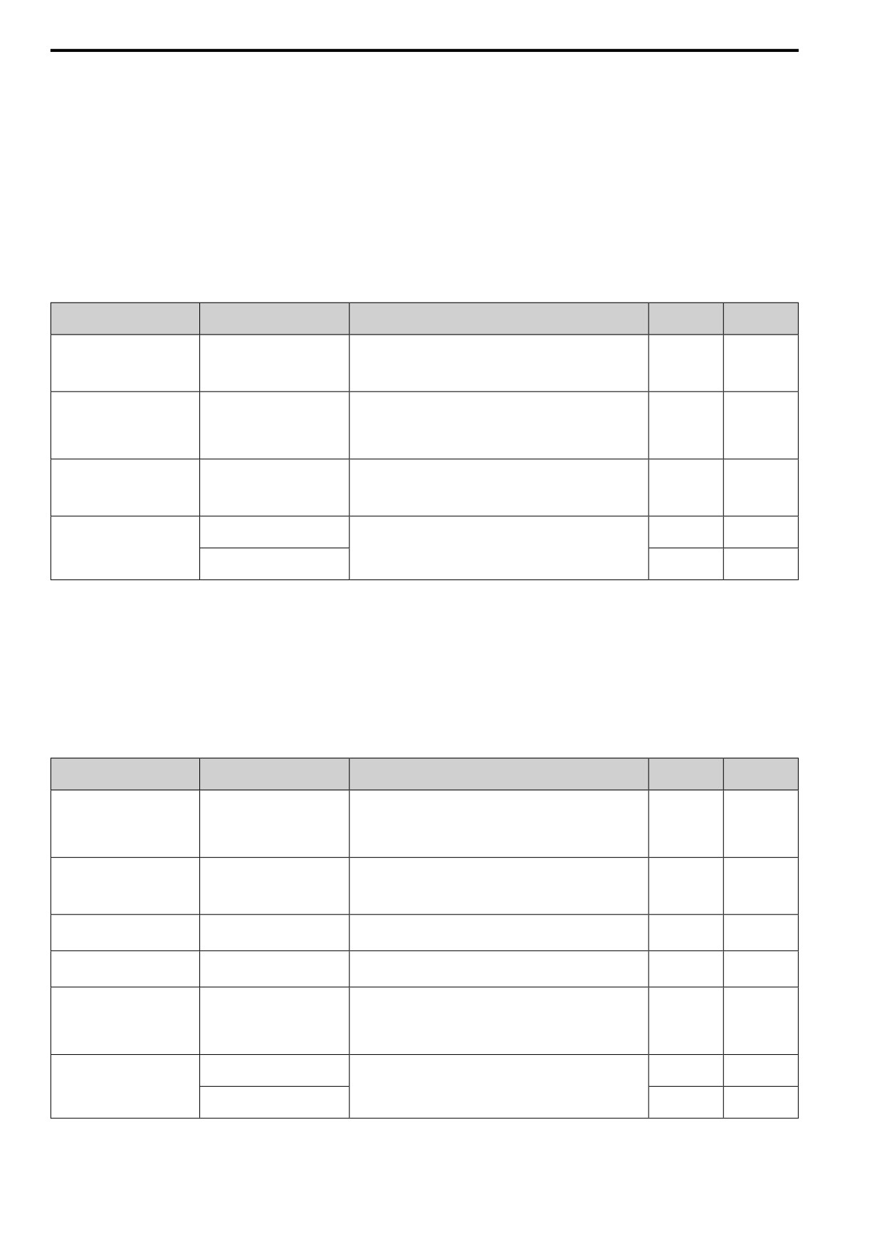
V/f Control on page 440 shows only the frequently adjusted parameters.
Note:
Torque and speed response for high-resistance and high-slip motors are slow. Adjust the torque and speed response to increase them.
Low impedance (low-slip) motors will hunt and oscillate. Adjust the torque and speed response to increase them.
■ V/f Control
When you use V/f Control, do not use C3-01 [Slip Comp Gain].
Table 12.4 Adjustment of Drive Control (V/f Control)
Adjustment Description
Parameter Number
Possible Solutions
Default
Recommen
ded Setting
• If the torque is not sufficient with heavy loads, decrease the
Prevent hunting and oscillation at
setting.
middle-range speeds (10 Hz to 40
n1-02 [HuntPrev Gain Setting]
1.00
0.50
- 2.00
Hz)
• If there is hunting or oscillation with light loads, increase the
setting. Set n1-01 = 1 [HuntPrev Selection = Enabled].
• Increasing motor excitation
sound
• If there is a loud motor excitation sound, increase the setting value.
C6-02 [Carrier Frequency
• Hunting and oscillation
• If there is hunting or oscillation at low speeds or middle-range
*1
1-F
Selection]
suppression at low speeds and
speeds, decrease the setting value.
middle-range speeds
• Increase torque at low speeds
• If the torque is not sufficient at low speeds, increase the setting
(10 Hz or lower)
value.
C4-01 [Trq Comp Gain]
1.00
0.50
- 1.50
• Prevent hunting and
• If there is hunting or oscillation with light loads, decrease the
oscillation
setting value.
13.0 V to 16.0
E1-08 [Mid A Voltage]
15.0 V *2 *3
• If the torque is not sufficient at low speeds, increase the setting
V *3
• Increase torque at low speeds
value.
• Prevent shock during start up
E1-10 [Min Output Voltage]
• If there is a large shock during start up, decrease the setting value.
9.0 V *2 *3
7.0 V to 10.0 V
*3
*1
The default setting changes when the settings for C6-01 [ND/HD Duty Selection] and o2-04 [Drive KVA Selection] change.
*2
The default setting changes when the settings for A1-02 [Control Method] and E1-03 [V/f Pattern Selection] change.
*3
This is the setting for 200 V class drives. Multiply the voltage by 2 for 400 V class drives.
■ Open Loop Vector Control Method
Do not adjust parameter C4-01 [Trq Comp Gain]. Keep this parameter at its default setting.
If you cannot get speed accuracy during regeneration, set C3-04 = 1 [Slip Comp@Regen = Enable>6 Hz]. If you
cannot get speed accuracy at high speeds, set C3-05 = 1 [Vout Limit Selection = Enabled].
Table 12.5 Adjustment of Drive Control (Open Loop Vector Control Method)
Adjustment description
Parameter Number
Possible Solutions
Default
Recommen
ded Setting
• Torque, increase speed
response
• If torque and speed response are slow, decrease the setting value.
• Prevent hunting and
n2-01 [AFR Gain]
1.00
0.50
- 2.00
• If there is hunting or oscillation, increase the setting value.
oscillation at middle-range
speeds (10 Hz to 40 Hz)
• Torque, increase speed
response
• If torque and speed response are slow, decrease the setting value.
20 ms to 100
C4-02 [Trq Comp Delay Time] *1
20 ms
• Prevent hunting and
• If there is hunting or oscillation, increase the setting value.
ms
oscillation
• Increase speed response
• When speed response is slow, decrease the setting value.
100 ms to 500
C3-02 [Slip Comp Delay Time]
200 ms
• Increase speed stability
• If speed is not stable, increase the setting value.
ms
• If speed is too slow, increase the setting value.
• Improve speed accuracy
C3-01 [Slip Comp Gain]
1.0
0.5
- 1.5
• If speed is too fast, decrease the setting value.
• Increasing motor excitation
sound
• If there is a loud motor excitation sound, increase the setting value.
C6-02 [Carrier Frequency
• Prevent hunting and
• If there is hunting or oscillation at low speeds, decrease the setting
*2
1-F
Selection]
oscillation at low-range speeds
value.
(10 Hz to or lower)
12.0 V to 13.0
• Increase torque and speed
E1-08 [Mid A Voltage]
• If the torque and speed response are slow, increase the setting
11.0 V *3
V *3
response at low speeds
value.
• Prevent shock during start up
• If there is a large shock during start up, decrease the setting value.
2.0 V to 3.0 V
E1-10 [Min Output Voltage]
2.0 V *3
*3
*1
If the value for C4-02 [Trq Comp Delay Time] is high, the current can increase during start up. Adjust and check the current during
start up.
440
12.1 A: INITIALIZATION
*2
The default setting changes when the settings for C6-01 [ND/HD Duty Selection] and o2-04 [Drive KVA Selection] change.
*3
This is the setting for 200 V class drives. Multiply the voltage by 2 for 400 V class drives.
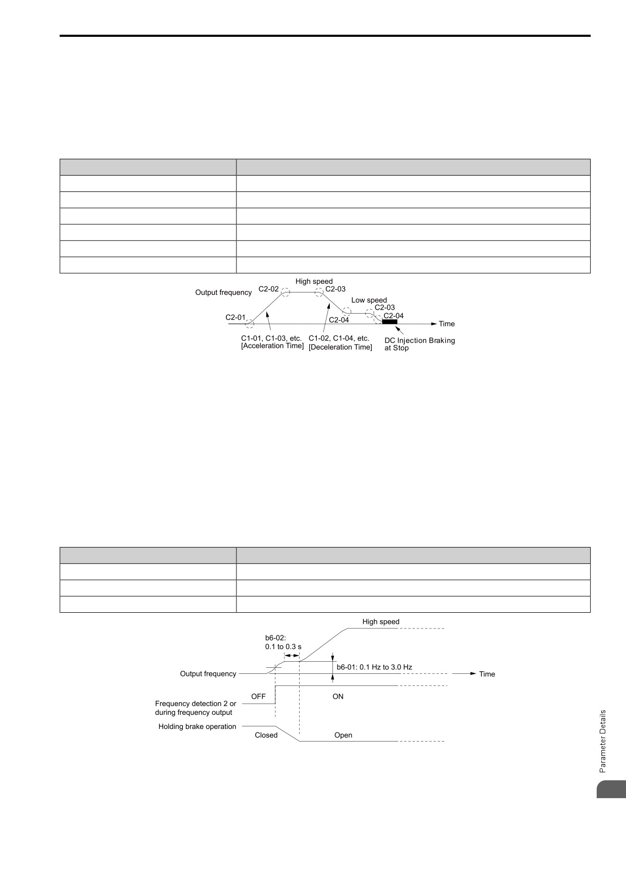
■ Elevator Start/Stop and Accel/Decel Time Shock Reduction
Shock when you start and stop the elevator and when you accelerate and decelerate is an issue for passenger
elevator applications. If shock has an effect on the quality of the ride, adjust these parameters:
■ S-Curve Characteristics, Accel & Decel Time
Adjustment Parameter
Name
C1-01, C1-03, C1-05, C1-07
Accel Time 1 to Accel Time 4
C1-02, C1-04, C1-06, C1-08
Decel Time 1 to Decel Time 4
C2-01
Jerk@Start of Accel
C2-02
Jerk@End of Accel
C2-03
Jerk@Start of Decel
C2-04
Jerk@End of Decel
Figure 12.4 S-curve Characteristics, Accel & Decel Time
Note:
• When decreased operation times are necessary for the application, for example with cranes and hoists, do not use S-curve characteristic
times.
• The default setting for C2-04 [Jerk@End of Decel] will be 0.00 seconds. The default setting for other S-curve characteristics will be
0.20 seconds. Set the acceleration/deceleration times and S-curve characteristic time correctly for acceleration/deceleration start up and
end. The recommended setting of the S-curve characteristics time is 0.2 to 1.0 seconds.
• When you use the C1-11 [Ac/Dec Switch Frequency], you can switch the acceleration/deceleration rate automatically during
acceleration/deceleration. The default setting is disabled.
When the Output Frequency ≥ C1-11, operate at the acceleration and deceleration times set in C1-01 and C1-02
When the Output Frequency < C1-11, operate at the acceleration and deceleration times set in C1-07 and C1-08
• During low speed operation, if the Output Frequency < E1-09 [Min Output Frequency] in the S-Curve Time @ Start of Decel, the
drive will cancel the S-curve characteristics and do DC Inject Braking at Stop.
■ Dwell Function at Start
Adjustment Parameter
Name
b6-01
Dwell Ref.@Start
b6-02
Dwell Time@Start
H2-xx = 14
FreqDetect 2
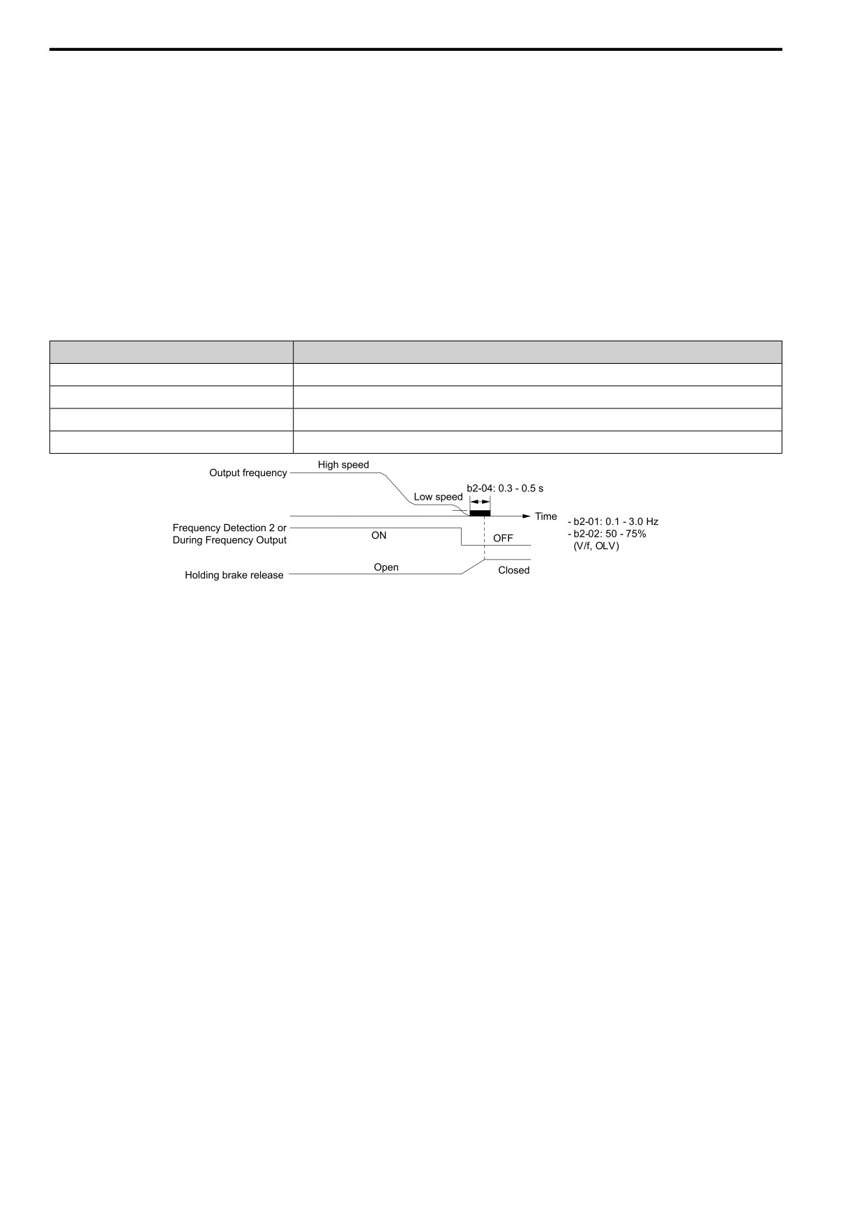
Figure 12.5 Dwell Function at Start
12
441
12.1 A: INITIALIZATION
Note:
• If the mechanical operation of the holding brake is slow, use the Dwell Function at Start to prevent brake grinding (friction). Accelerate
after the brake is fully open.
• When you use V/f Control or Open Loop Vector Control, set b6-01 [Dwell Ref.@Start] > Frequency Detection 2 (brake open
frequency).
• If the motor torque is not sufficient during start up, use the DC Inject Braking function to secure the motor current (torque) before you
start the motor.
-b2-02 [DCI Braking Current] recommended setting: 50% to 75% (V/f Control, Open Loop Vector Control)
-b2-03 [DCInj Time@Start] recommended setting: 0.2 s to 0.5 s
■ DC Injection Braking at Stop Function
Note:
If you disconnect a drive from a motor when it is controlling the motor or during DC Injection Braking (Zero speed level), a voltage
surge can trigger a drive fault. When you use an electromagnetic contactor between the drive and motor, set L8-07 = 1 or 2 [Out
PhaseLoss Selection = 1PH Loss Det, or 2/3PH Loss Det]. If it necessary to disconnect the motor and drive when you stop the elevator,
fully close the holding brake and disconnect the drive while the Baseblock signal is ON. This does not apply for emergency conditions.
Adjustment Parameter
Name
b2-01
ZSpd/DCI Threshold
b2-02
DCI Braking Current
b2-04
DCInj Time@Stop
H2-xx = 5
FreqDetect 2
Figure 12.6 DC Injection Braking at Stop Function
Note:
• If the mechanical operation of the holding brake is slow, use DC Injection Braking until the brake is fully closed to prevent rollback.
• If you cannot hold the load with DC Injection Braking when it is stopped in V/f Control and Open Loop Vector Control modes, use
Dwell Function at Stop.
-b6-03 [Dwell Ref@Stop]: Minimum output frequency to 3.0 Hz
When Frequency Detection 2 is OFF, it is less than L4-01 [SpAgree Det.Level] - L4-02 [SpAgree Det.Width].
-b6-04 [Dwell Time@Stop] recommended setting: 0.3 s to 0.5 s
-b2-04 [DCInj Time@Stop] recommended setting: 0.0 s
■ Analog Input FilterTime Constant
When b1-01 = 1 [Freq. Ref. Sel. 1 = Analog Input], it adds noise to the analog frequency reference during run.
• Minimize the effects of noise.
• Change H3-13 [An.In FilterTime Constant] to a range of 0.01 s to 0.10 s.
■ Startup Current Check
When you do a test run, set L8-41 =1 [HCA alarm Selection = Enabled] and use U4-13 [Peak Hold Current] and
a clamp ammeter with the machine under load and not under load to check the motor current during start up.
If the motor torque is not sufficient during start up or if the timing between the motor and the holding brake is
unsatisfactory and causes the motor to lock, a large quantity of current will flow. In these conditions, adjust the
parameters again and decrease the load to decrease the current to less than 150%. If the current flow is more than
150% of the drive rated current, the heat stress on the IGBTs will decrease the service life of drive parts.
To decrease the effects of heat stress, decrease the carrier frequency of the drive to 2.0 kHz to 2.5 kHz for
applications where low audible noise is not necessary.
■ Overvoltage Suppression Function
If the overvoltage suppression function is used in elevator type applications, there is a risk of rollback and falls.
Set L3-11 = 0 [Overvolt Supression Select = Disabled].
442
12.1 A: INITIALIZATION
The overvoltage suppression function is designed to prevent an overvoltage trip in a situation in which a braking
resistor is not used with a regenerative load. If the overvoltage suppression function is enabled, the regeneration
torque reference within the drive is automatically controlled during regeneration.
Note:
When using the drive for applications such as high speed elevators with a speed of 2 ms or more and direct drive elevators, or when you
need drives designed for cranes, contact the manufacturer or your sales representative.
12
443
12.2 b: APPLICATION
12.2
b: APPLICATION
b parameters set these functions:
• Frequency reference source/Run command source
• Stopping method settings
• DC Injection Braking
• Speed Search
• Timer Function
• PID control
• Dwell function
• Energy-Saving Control
◆ b1: OPERATION MODE SELECT
b1 parameters set the operation mode for the drive.
■ b1-01: Freq. Ref. Sel. 1
No.
Default
Name
Description
(Hex.)
(Setting Range)
V/f
OLV OLV/PM AOLV/PM EZOLV
b1-01
Freq. Ref. Sel. 1
1
(0180)
Sets the input method for the frequency reference.
(0 - 4)
Note:
• Push
on the keypad to set the input mode to LOCAL and use the keypad to enter the frequency reference.
• If the frequency reference is 0 Hz or less than the value set in E1-09 [Min Output Frequency] and the drive receives the Run command,
the RUN LED on the keypad will flash. Examine the setting for the frequency reference input and enter a value ≥ E1-09.
0 : Keypad
Use the keypad to enter the frequency reference.
Use
and
on the keypad to change the frequency reference.
1 : Analog Input
Use MFAI terminals AI1 and AI2 to input an analog frequency reference with a voltage or current input signal.
• Voltage Input
Refer to Table 12.6 to use a voltage signal input to one of the MFAI terminals.
Table 12.6 Frequency Reference Voltage Input
Parameter Settings
Terminal Signal
Terminal
Note
Level
Signal Level
Function Selection
Gain
Bias
Selection
AI1
0 - 10 V (Lower Limit
H3-01 = 0
H3-02 = 4
H3-03
H3-04
at 0)
[Freq Ref/BIAS]
-
0 - 10 V (Bipolar
H3-01 = 1
Reference)
AI2
0 - 10 V (Lower Limit
H3-01 = 0
H3-10 = 4
H3-11
H3-12
Set DIP switch S1 to “V” for
at 0)
voltage input.
[Freq Ref/BIAS]
0 - 10 V (Bipolar
H3-01 = 1
Reference)
444
12.2 b: APPLICATION
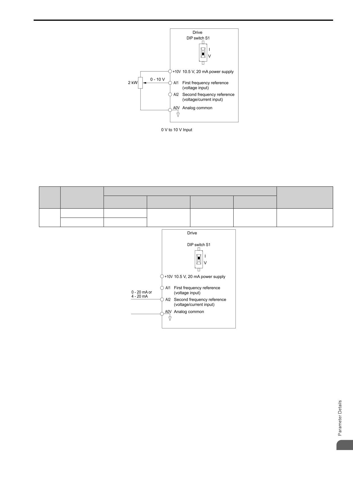
Figure 12.7 Example of Setting the Frequency Reference with a Voltage Signal to Terminal AI1
Note:
You can also use this diagram to wire terminal AI2.
• Current Input
Refer to Table 12.7 to use a current signal input to one of the MFAI terminals.
Table 12.7 Frequency Reference Current Input
Parameter Settings
Terminal
Signal Level
Note
Signal Level
Function Selection
Gain
Bias
Selection
A2
4 - 20 mA
H3-09 = 2
H3-10 = 4
H3-11
H3-12
Set DIP switch S1 to “I” for
current input.
[Freq Ref/BIAS]
0 - 20 mA
H3-09 = 3
Figure 12.8 Example of Setting the Frequency Reference with a Current Signal to Terminal AI2
Changing between Master and Auxiliary Frequency References
Use the multi-step speed reference function to change the frequency reference input between terminals AI1 and
AI2.
2 : Modbus
Use Modbus communications to enter the frequency reference.
3 : Option PCB
Use a communications option connected to the drive to enter the Run command.
Refer to the instruction manual included with the option to install and set the option.
Note:
If b1-01 = 3 but you did not connect an option, oPE05 [Run Cmd/Freq Ref Source Sel Err] will flash on the keypad.
4 : Pulse Train Input
Use a pulse train signal from the pulse train input terminal PI to enter the frequency reference.
12
Do this procedure to make sure that the pulse train signal is operating correctly.
1. Set b1-01 = 4, H6-01 = 0 [PI Pulse Train Function = Freq Ref].
445
12.2 b: APPLICATION
2. Set H6-02 [PI Frequency Scale] to the number of pulses that determine 100% of the frequency reference.
3. Enter a pulse train signal on the terminal PI and make sure that the keypad shows a correct frequency
reference.
■ b1-02: Run Comm. Sel 1
No.
Default
Name
Description
(Hex.)
(Range)
b1-02
Run Comm. Sel 1
V/f
OLV OLV/PM AOLV/PM EZOLV
1
(0181)
Sets the input method for the Run command.
(0 - 3)
0 : Keypad
Use the keypad to enter the Run command.
You can use the JOG operation or the FWD/REV commands from the keypad.
Note:
The
on the keypad is on while keypad is the Run command source.
1 : Analog Input
Use the control circuit terminals to enter the Run command. Select the input method for the Run command with
an H1-xx parameter.
Set H1-xx = 1 to 5 [Forward Run to 3-Wire Seq.]. The default setting is 2-wire sequence 1.
•
2-wire Sequence 1
This sequence has two input types: FWD/Stop and REV/Stop. Set A1-03 = 2220 [Init Parameters = 2-Wire
Initialization] to initialize the drive and set terminals DI1 and DI2 for a 2-wire sequence.
•
2-wire Sequence 2
This sequence has two input types: Run/Stop and FWD/REV.
•
3-Wire Sequence (3-Wire Seq.)
This sequence has three input types: Run, Stop, and FWD/REV. Set A1-03 = 3330 [Init Parameters = 3-Wire
Initialization] to initialize the drive and set terminals DI1, DI2, and DI5 for a 3-wire sequence.
2 : Modbus
Use Modbus communications to enter the Run command.
3 : Option PCB
Use a communications option card or input option card connected to the drive to enter the Run command.
Refer to the instruction manual included with the option card to install and set the option card.
Note:
If b1-02 = 3 but no connected option card, then oPE05 [Run Cmd/Freq Ref Source Sel Err] will flash on the keypad.
■ b1-03: Stopping Method Selection
No.
Default
Name
Description
(Hex.)
(Range)
b1-03
Stopping Method Selection
V/f
OLV OLV/PM AOLV/PM EZOLV
0
(0182)
Sets the method to stop the motor after removing a Run command or entering a Stop command.
(0 - 3, 9)
Note:
When A1-02 = 5, 6, 8 [Control Method = PM OLVector, PM AOLVector, EZ Vector], the setting range is 0, 1, 3.
Select the applicable stopping method for the application from these four options:
0 : Ramp->Stop
When you enter the Stop command or turn OFF the Run command, the drive ramps the motor to stop.
The drive ramps the motor to stop as specified by the deceleration time. The default setting for the deceleration
time is C1-02 [Decel Time 1]. The actual deceleration time changes as the load conditions change (for example,
mechanical loss and inertia).
If the output frequency is less than or equal to the value set in b2-01 [ZSpd/DCI Threshold] during deceleration,
the drive will do DC Injection Braking, Zero Speed Control, or Short Circuit Braking, as specified by the control
method.
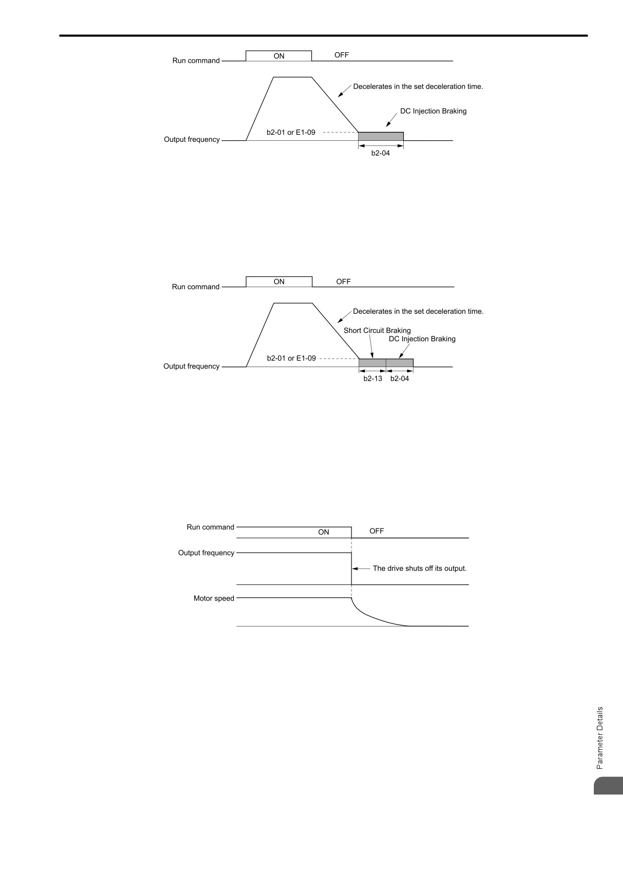
• Ramp to Stop with V/f Control and OLV Control Methods
Parameter b2-01 sets the frequency to start DC Injection Braking at stop. If the output frequency is less than or
equal to the value set in b2-01 during deceleration, then the drive will perform DC Injection Braking for the
time set in b2-04 [DCInj Time@Stop].
446
12.2 b: APPLICATION
Figure 12.9 Ramp to Stop with V/f and OLV Control Methods
Note:
When b2-01 ≤ E1-09 [Min Output Frequency], the drive will start DC Injection Braking from the frequency set in E1-09.
• Ramp to Stop with OLV/PM, AOLV/PM, and EZOLV Control Methods
Parameter b2-01 sets the frequency to start Short Circuit Braking. When the output frequency is less than or
equal to the value set in b2-01 during deceleration, then the drive will do Short Circuit Braking for the time set
in b2-13 [SCB Time@Stop]. When b2-04 ≠ 0, the drive will do DC Injection Braking for the time set in b2-04
when Short Circuit Braking is complete.
Figure 12.10 Ramp to Stop with OLV/PM, AOLV/PM, and EZOLV Control Methods
Note:
When b2-01 ≤ E1-09, the drive will start Short Circuit Braking from the frequency set in E1-09.
If b2-01 = 0 Hz and E1-09 = 0 Hz, the drive will not do Short Circuit Braking.
1 : Coast->Stop
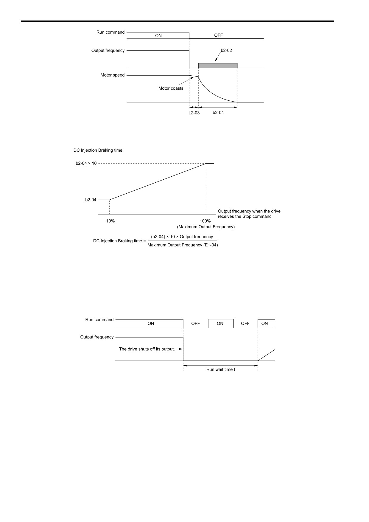
When you enter the Stop command or turn OFF the Run command, the drive turns OFF the output and coasts the
motor to stop.
Load conditions will have an effect on the deceleration rate as the motor coasts to stop (for example, mechanical
loss and inertia).
Figure 12.11 Coast to Stop
Note:
When you enter the Stop command or turn OFF the Run command, the drive ignores the Run command for the time set in L2-03 [Min
Baseblck Time]. Do not enter the Run command until the motor comes to a complete stop. Use DC Injection or Speed Search to restart
the motor before it stops.
2 : DC Inj->Stop
When you enter the Stop command or turn OFF the Run command, the drive turns OFF the output for the time set
in L2-03. The drive waits for the minimum baseblock time and then injects the amount of DC current into the
motor set in b2-02 [DCI Braking Current] to stop the motor with DC current.
DC Injection Braking stops the motor more quickly than coast to stop.
Note:
12
If A1-02 = 5, 6, DC Injection Braking to Stop is not available.
447
12.2 b: APPLICATION
Figure 12.12 DC Injection Braking to Stop
The value set in b2-04 and the output frequency when the drive receives the Stop command determine the DC
Injection Braking time. The drive calculates the DC Injection Braking time as in Figure 12.13.
Figure 12.13 DC Injection Braking Time and Output Frequency
Note:
Set L2-03 to a high value that will not trigger oC [Overcurrent] when the drive uses DC Injection Braking to stop the motor.
3 : Timed Coast->Stop
Enter the Stop command or turn OFF the Run command and turn OFF drive output and coast the motor to stop.
The drive ignores the Run command until the “Run wait time t” is expired.
To start the drive again, wait until the the “Run wait time t” is expired then enter the Run command.
Figure 12.14 Coast to Stop with Timer
The active deceleration time and the output frequency when drive receives the Stop command determine the
length of “Run wait time t”.
448
12.2 b: APPLICATION
Figure 12.15 Run Wait Time and Output Frequency
9 : Distance Stop
Enter the Stop command or turn OFF the Run command for the drive to always decelerate for the same distance.
The drive uses the active deceleration time and the value set in E1-04 [Max Output Frequency] to calculate
stopping distance S1. The drive holds its current speed when stopping from a frequency less than the maximum
speed. When the distance covered is equal to S1 minus S2, the drive ramps to stop in the current deceleration
time. Adjust the stopping precision with d4-12 [Stop Position Gain].
Figure 12.16 Deceleration When Set for Stop in Position
Note:
Note these points when setting Stop in Position.
• The drive uses the deceleration time that was active when the drive received the Stop command or when the Run command was turned
OFF to calculate the stop time. If you change the deceleration time during deceleration, the positioning will not be accurate.
• Set b6-03 = 0.0 [Dwell Ref@Stop = 0.0], b6-04 = 0.0 [Dwell Time@Stop = 0.0 s].
• The KEB Ride-Thru function is not available. Set H1-xx ≠ 40, 41, 42, 43 [MFDI Function Selection = KEB Thru1 NC, KEB Thru1
NO, KEB Thru2 NC, KEB Thru2 NO].
• Set L3-04 = 0 [StallP@Decel Enable = Disabled]. A dynamic braking option can be necessary for regenerative loads.
• Set L3-11 = 0 [Overvolt Supression Select = Disabled].
• The High Slip Braking function is not available. Set H1-xx ≠ 32 [MFDI Function Selection ≠ HiSlipBraking].
• Set C2-03, C2-04 = 0.00 [Jerk@Start of Decel, Jerk@End of Decel = 0.00 s].
■ b1-04: Reverse Operation Selection
No.
Default
Name
Description
(Hex.)
(Range)
b1-04
Reverse Operation
V/f
OLV OLV/PM AOLV/PM EZOLV
0
Selection
(0183)
Sets the reverse operation function. Disable reverse operation in fan or pump applications where
(0, 1)
reverse rotation is dangerous.
When reverse operation is prohibited, the drive will not accept a Reverse operation command.
0 : Enabled
The drive will accept a Reverse operation command.
1 : Disabled
The drive will not accept a Reverse operation command.
12
449
12.2 b: APPLICATION
■ b1-06: Double Scan DI Inputs Select
No.
Default
Name
Description
(Hex.)
(Range)
b1-06
Double Scan DI Inputs
V/f
OLV OLV/PM AOLV/PM EZOLV
2
Select
(0185)
Sets the number of times that the drive reads the sequence input command to prevent malfunction
(1, 2)
because of noise.
1 : Single Scan
The drive reads the terminal status one time. The drive immediately reads all changes to the terminal status.
This setting lets the drive quickly respond to changes in the sequence, but noise can cause malfunction.
2 : Double Scan
The drive reads the terminal status two times. The drive reads all changes to the terminal status two times to make
sure that the reading is the same.
The drive responds slower than when it reads the sequence one time, but this setting prevents malfunction because
of noise.
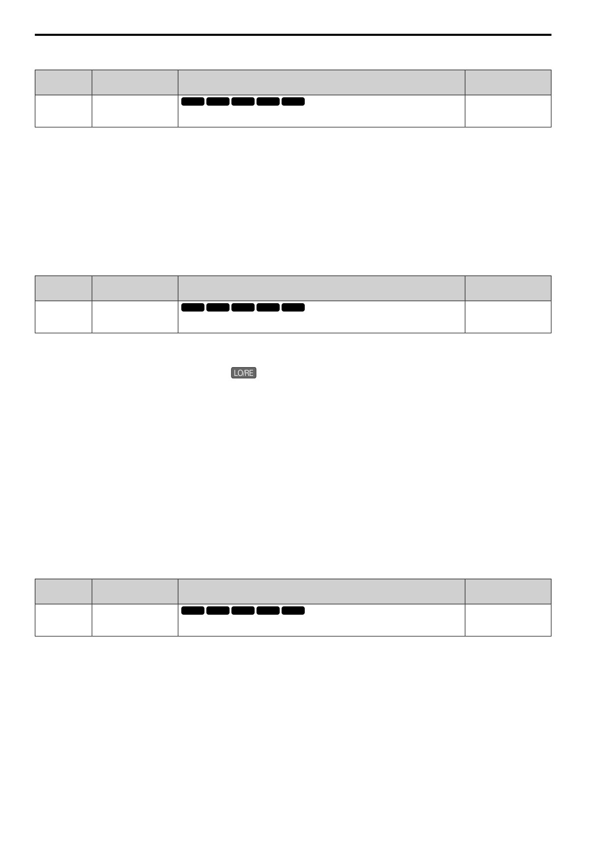
■ b1-07: LO/RE Run Selection
No.
Default
Name
Description
(Hex.)
(Range)
b1-07
LO/RE Run Selection
V/f
OLV OLV/PM AOLV/PM EZOLV
1
(0186)
Sets drive response to an existing Run command when the drive receives a second Run command
(1, 2)
from a different location.
This parameter interlocks the drive to help prevent accidents that can occur if the motor starts to rotate because the
Run command source changed.
To switch the RUN command source, push
on the keypad or set H1-xx = 11, 9 [MFDI Function Select =
LOC/REM Sel., Ext Ref 1/2] and activate/deactivate the terminal.
1 : Cycle RUN
If a Run command is enabled when you switch between Run command sources, the drive will not operate the
motor.
When the drive is operating the motor, turn OFF the Run command to stop the motor. Enter the Run command
again to start operation.
2 : Accept RUN
If a Run command is enabled when you switch between Run command sources, the drive will start to operate the
motor or continue to operate the motor.
WARNING! Sudden Movement Hazard. When you use a 3-Wire sequence, set A1-03 = 3330 [Init Parameters = 3-Wire
Initialization] and make sure that b1-17 = 1 [RUN@PowerUp Selection = Disregard RUN] (default). If you do not correctly set
the drive parameters for 3-Wire operation before you energize the drive, the motor can suddenly rotate in reverse when you
energize the drive.
■ b1-08: RUN@PRG Mode Selection
No.
Default
Name
Description
(Hex.)
(Range)
b1-08
RUN@PRG Mode
V/f
OLV OLV/PM AOLV/PM EZOLV
1
Selection
(0187)
Sets the conditions for the drive to accept a Run command entered from an external source when
(1 - 3)
using the keypad to set parameters.
As a safety precaution, when the drive is in Programming Mode, it will not respond to a Run command.
This parameter helps prevent accidents that can occur if the motor starts to rotate because the drive received a Run
command from an external source while the user is programming the drive. You can also set the drive to not show
the Programming Mode when a Run command is active.
1 : NoRUN@Program
The drive rejects the Run command while in Programming Mode.
2 : RUN@Program
The drive accepts a Run command entered from an external source while in Programming Mode.
3 : Program@Stop only
The drive does not let the user enter Programming Mode when the drive is operating. The drive does not show the
Programming Mode when a Run command is active.
450
12.2 b: APPLICATION
■ b1-14: Phase Order Selection
No.
Default
Name
Description
(Hex.)
(Range)
b1-14
Phase Order Selection
V/f
OLV OLV/PM AOLV/PM EZOLV
0
(01C3)
Sets the phase order for output terminals U/T1, V/T2, and W/T3. This parameter can align the
(0, 1)
Forward Run command from the drive and the forward direction of the motor without changing
wiring.
0 : Standard
1 : Phase Order Switch
■ b1-15: Freq. Ref. Sel. 2
No.
Default
Name
Description
(Hex.)
(Range)
b1-15
Freq. Ref. Sel. 2
V/f
OLV OLV/PM AOLV/PM EZOLV
0
(01C4)
Sets the input method for frequency reference 2.
(0 - 4)
This parameter is enabled when H1-xx = 9 [MFDI Function Select = Ext Ref 1/2] is activated.
Note:
• Push
on the keypad to set the input mode to LOCAL and use the keypad to enter the frequency reference.
• If the frequency reference is 0 Hz or less than or equal to the value set in E1-09 [Min Output Frequency] and the drive receives the Run
command, the RUN LED on the keypad will flash. Examine the setting for the frequency reference input and enter a value more than
or equal to E1-09.
0 : Keypad
Use the keypad to enter the frequency reference.
Use
and
on the keypad to change the frequency reference.
1 : Analog Input
Use MFAI terminals AI1 and AI2 to input an analog frequency reference with a voltage or current input signal.
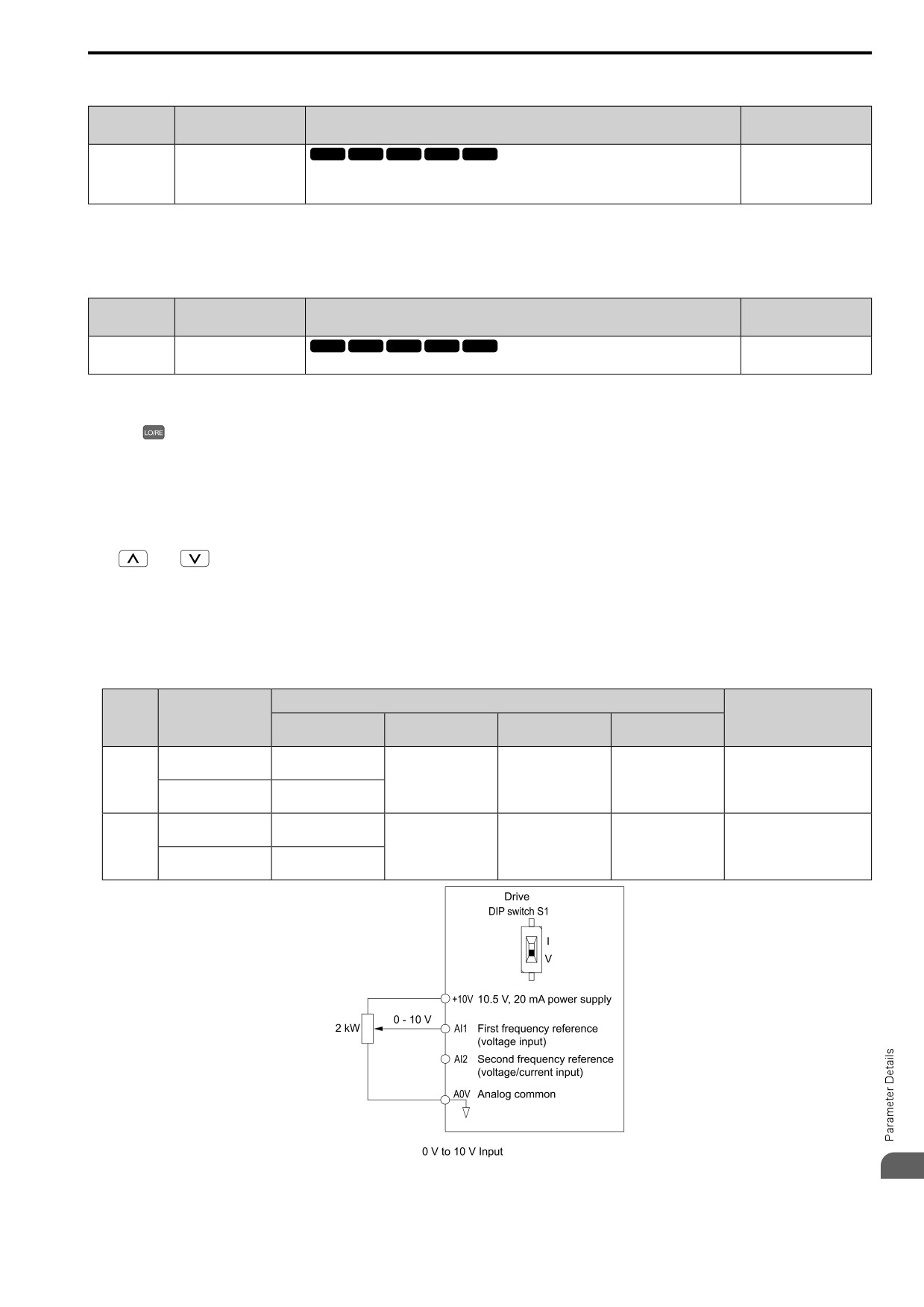
• Voltage Input
Refer to Table 12.8 to use a voltage signal input to one of the MFAI terminals.
Table 12.8 Frequency Reference Voltage Input
Parameter Settings
Terminal Signal
Terminal
Note
Level
Signal Level
Function Selection
Gain
Bias
Selection
AI1
0 - 10 V (Lower Limit
H3-01 = 0
H3-02 = 4
H3-03
H3-04
at 0)
[Freq Ref/BIAS]
-
0 - 10 V (Without
H3-01 = 1
Lower Limit)
AI2
0 - 10 V (Lower Limit
H3-01 = 0
H3-10 = 4
H3-11
H3-12
Set DIP switch S1 to “V” for
at 0)
voltage input.
[Freq Ref/BIAS]
0 - 10 V (Without
H3-01 = 1
Lower Limit)
12
Figure 12.17 Example of Setting the Frequency Reference with a Voltage Signal to Terminal AI1
451
12.2 b: APPLICATION
Note:
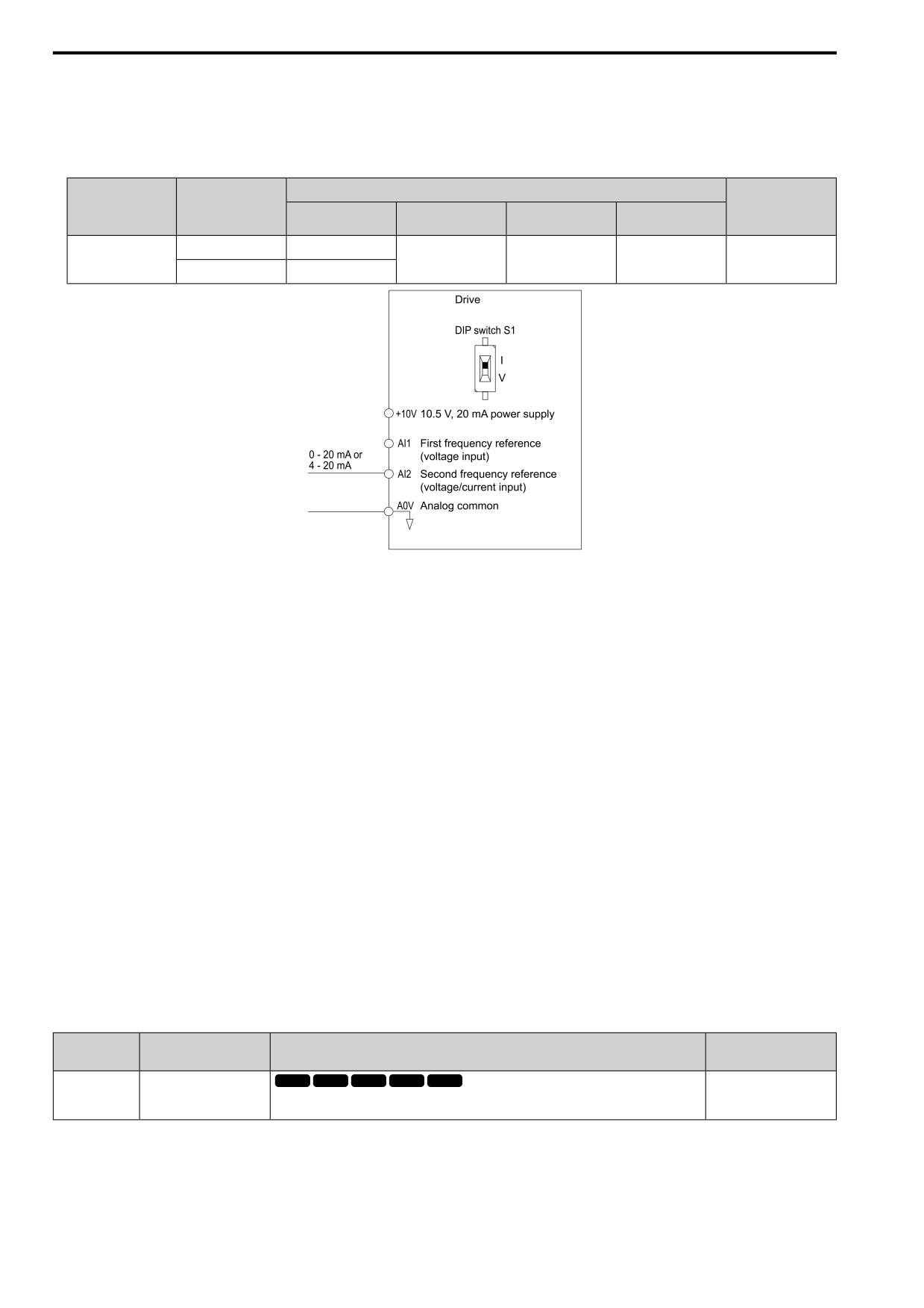
You can also use this diagram to wire terminal AI2.
• Current Input
Refer to Table 12.9 to use a current signal input to one of the MFAI terminals.
Table 12.9 Frequency Reference Current Input
Parameter Settings
Terminal
Signal Level
Note
Signal Level
Function Selection
Gain
Bias
Selection
AI2
4 - 20 mA
H3-09 = 2
H3-10 = 4
H3-11
H3-12
Set DIP switch S1 to
“I” for current input.
[Freq Ref/BIAS]
0 - 20 mA
H3-09 = 3
Figure 12.18 Example of Setting the Frequency Reference with a Current Signal to Terminal AI2
Changing between Master and Auxiliary Frequency References
Use the multi-step speed reference function to change the frequency reference input between terminals AI1 and
AI2.
2 : Modbus
Use Modbus communications to enter the frequency reference.
3 : Option PCB
Use a communications option card connected to the drive to enter the Run command.
Refer to the instruction manual included with the option card to install and set the option card.
Note:
If you set b1-15 = 3 but you do not connect an option card, oPE03 [Multi-Function Input Setting Err] will flash on the keypad.
4 : Pulse Train Input
Use a pulse train signal from the pulse train input terminal PI to enter the frequency reference.
Do this procedure to make sure that the pulse train signal is operating correctly.
1. Set b1-15 = 4, H6-01 = 0 [PI Pulse Train Function = Freq Ref].
2. Set H6-02 [PI Frequency Scale] to the number of pulses that determine 100% of the frequency reference.
3. The terminal set in H1-xx = 9 [MFDI Function Select = Ext Ref 1/2] is activated.
4. Enter a pulse train signal on the terminal PI and make sure that the keypad shows a correct frequency
reference.
■ b1-16: Run Comm. Sel 2
No.
Default
Name
Description
(Hex.)
(Range)
b1-16
Run Comm. Sel 2
V/f
OLV OLV/PM AOLV/PM EZOLV
0
(01C5)
Sets the input method for Run Command 2 when the user switches the control circuit terminals
(0 - 3)
ON/OFF to change the Run command source.
Activate H1-xx = 2 [MFDI Function Select = External Reference 1/2 Selection] to enable this parameter.
0 : Keypad
Use the keypad to enter the Run command.
You can use the JOG operation or the FWD/REV commands from the keypad.
452
12.2 b: APPLICATION
Note:
The
is on while the keypad is the Run command source.
1 : Analog Input
Use the control circuit terminals to enter the Run command. Select the input method for the Run command with
an H1-xx parameter.
Set H1-xx = 1 to 5 [Forward Run to FWD/REV Cmd, 3-Wire Seq.]. The default setting is 2-wire sequence 1.
•
2-wire Sequence 1
This sequence has two input types: FWD/Stop and REV/Stop. Set A1-03 = 2220 [Init Parameters = 2-Wire
Initialization] to initialize the drive and set terminals DI1 and DI2 for a 2-wire sequence.
•
2-wire Sequence 2
This sequence has two input types: Run/Stop and FWD/REV.
•
3-Wire Sequence
This sequence has three input types: Run, Stop, and FWD/REV. Set A1-03 = 3330 [Init Parameters = 3-Wire
Initialization] to initialize the drive and set terminals DI1, DI2, and DI5 for a 3-wire sequence.
2 : Modbus
Use Modbus communications to enter the Run command.
3 : Option PCB
Use a communications option card or input option card connected to the drive to enter the Run command.
Refer to the instruction manual included with the option card to install and set the option card.
Note:
If b1-16 = 3 but no option card is connected, then oPE03 [Multi-Function Input Setting Err] will flash on the keypad.
■ b1-17: RUN@PowerUp Selection
No.
Default
Name
Description
(Hex.)
(Range)
V/f
OLV OLV/PM AOLV/PM EZOLV
b1-17
RUN@PowerUp Selection
1
(01C6)
Sets drive response when energizing a drive that has an external Run command. Set this
(1, 2)
parameter in applications where energizing or de-energizing the drive enables the Run command.
1 : Disregard RUN
The drive does not start to operate the application when the power is switched ON, even when there is an existing
Run command.
Enter the Run command again to operate the application.
Note:
When you energize the drive,
on the keypad will flash quickly if the Run command is already enabled from an external source.
2 : Accept RUN
When there is an existing Run command, the drive starts to operate the application when the power is switched
ON.
WARNING! Sudden Movement Hazard. When you use a 3-Wire sequence, set A1-03 = 3330 [Init Parameters = 3-Wire
Initialization] and make sure that b1-17 = 1 [RUN@PowerUp Selection = Disregard RUN] (default). If you do not correctly set
the drive parameters for 3-Wire operation before you energize the drive, the motor can suddenly rotate in reverse when you
energize the drive.
■ b1-35: DI Deadband Time
No.
Default
Name
Description
(Hex.)
(Range)
b1-35
DI Deadband Time
V/f
OLV OLV/PM AOLV/PM EZOLV
0.0 ms
(1117)
Sets the deadband time for MFDIs.
(0.0 to 100.0 ms)
Expert
When the on/off time for MFDIs is longer than the time set in b1-35, the drive activates the MFDI. Set this
parameter to prevent malfunctions caused by relay chattering for applications in which relays send input to MFDI
terminals.
12
453
12.2 b: APPLICATION
◆ b2: DC INJ / SHORT CKT BRAKE
b2 parameters set the DC Injection Braking and Short Circuit Braking functions.
• DC Injection Braking: A braking method that injects DC current into the motor windings. This function should
not be used too frequently, because it generates a fair amount of heat in the motor.
• Short Circuit Braking: A braking method for PM motors.
■ b2-01: ZSpd/DCI Threshold
No.
Default
Name
Description
(Hex.)
(Range)
b2-01
ZSpd/DCI Threshold
V/f
OLV OLV/PM AOLV/PM EZOLV
Determined by A1-02
(0189)
Sets the frequency to start DC Injection Braking or Short Circuit Braking.
(0.0 - 10.0 Hz)
Note:
This parameter is available when b1-03 = 0 [Stopping Method Selection = Ramp->Stop].
When the control method selected in A1-02 [Control Method] changes, the b2-01 function changes.
Parameter Settings
Functions of b2-01
A1-02 = 0, 2 [V/f Control or OLVector]
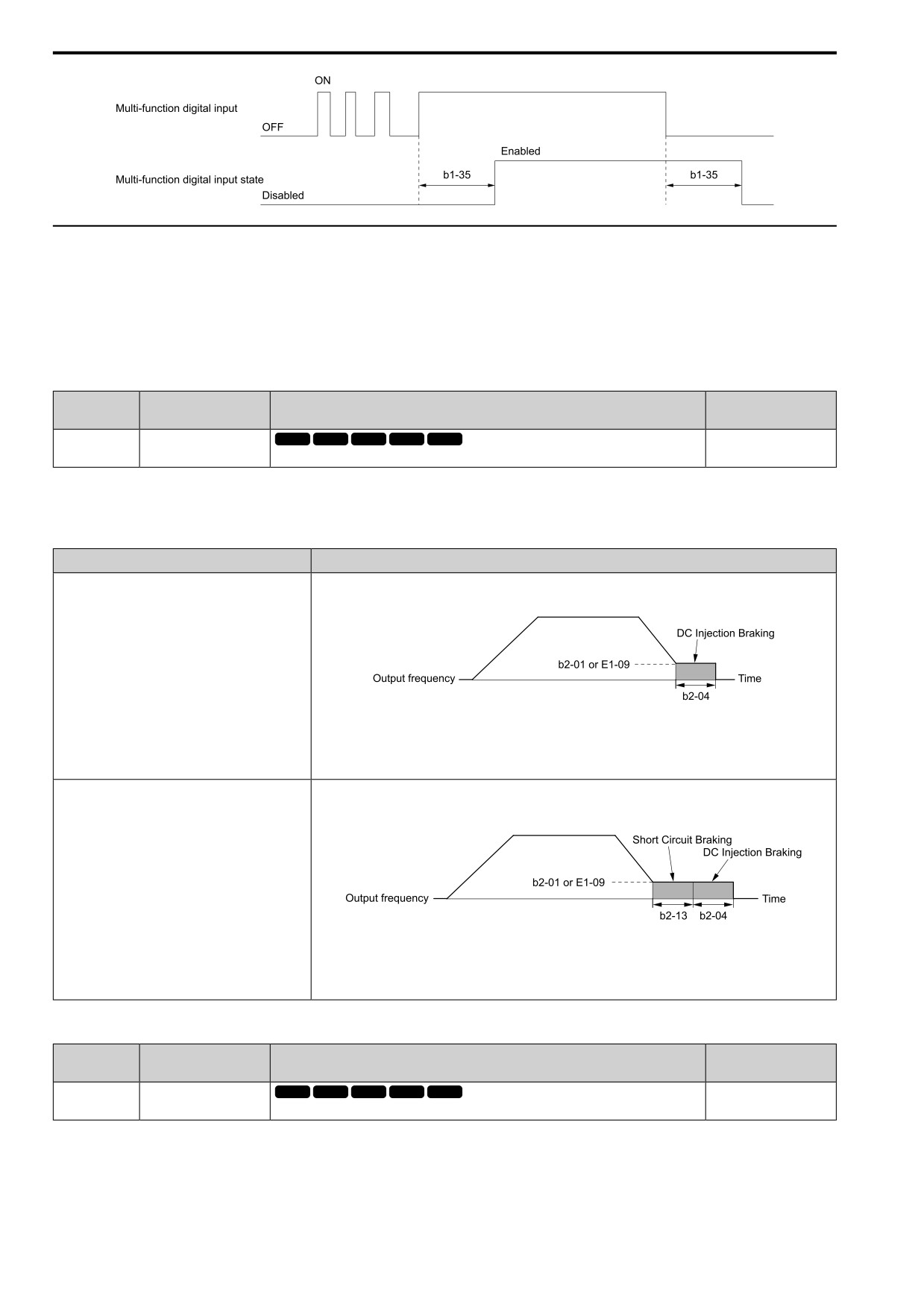
Parameter b2-01 sets the frequency to start DC Injection Braking at stop. When the output frequency is less than or
equal to the value set in b2-01, the drive will inject the quantity of DC current set in b2-02 [DCI Braking Current] into
the motor for the time set in b2-04 [DC Inject Braking Time at Stop].
Figure 12.19 DC Injection Braking at Stop
Note:
When b2-01 ≤ E1-09 [Min Output Frequency], the drive will start DC Injection Braking from the frequency set in
E1-09.
A1-02 = 5, 6, or 8 [PM OLVector, PM AOLVector, or EZ
Parameter b2-01 sets the frequency to start for Short Circuit Braking at stop. When the output frequency is less than or
Vector]
equal to the value set in b2-01, the drive will do Short Circuit Braking for the time set in b2-13 [SCB Time@Stop].
When b2-04 > 0.00 s, the drive will complete Short Circuit Braking, then do DC Injection Braking for the time set in
b2-04.
Figure 12.20 Short Circuit Braking at Stop
Note:
When b2-01 ≤ E1-09, the drive will start Short Circuit Braking from the frequency set in E1-09. If b2-01 and E1-
09 = 0 Hz, the drive will not do Short Circuit Braking.
■ b2-02: DCI Braking Current
No.
Default
Name
Description
(Hex.)
(Range)
V/f
OLV OLV/PM AOLV/PM EZOLV
b2-02
DCI Braking Current
50%
(018A)
Sets the DC Injection Braking current as a percentage of the drive rated current.
(0 - 75%)
When the DC Injection Braking current is more than 50%, the drive decreases the carrier frequency to 1 kHz. The
motor rated current determines how much DC Injection Braking current that the drive can use.
454
12.2 b: APPLICATION
The DC Injection Braking current level has an effect on the strength of the magnetic field that locks the motor
shaft. As the current level increases, the motor windings will supply more heat. Do not set this parameter higher
than the level that is necessary to hold the motor shaft.
■ b2-03: DCInj Time@Start
No.
Default
Name
Description
(Hex.)
(Range)
b2-03
DCInj Time@Start
V/f
OLV OLV/PM AOLV/PM EZOLV
0.00 s
(018B)
Sets the DC Injection Braking Time at stop.
(0.00 - 10.00 s)
This function stops then restarts a coasting motor and increases motor flux to make high starting torque (a process
called initial excitation). Set this parameter to 0.00 to disable the function.
Note:
To restart a coasting motor, use DC Injection Braking to stop and then restart the motor, or enable Speed Search. Enable DC Injection
Braking or Speed Search to prevent ov [Overvoltage] or oC [Overcurrent] faults.
■ b2-04: DCInj Time@Stop
No.
Default
Name
Description
(Hex.)
(Range)
V/f
OLV OLV/PM AOLV/PM EZOLV
b2-04
DCInj Time@Stop
Determined by A1-02
(018C)
Sets the DC Injection Braking Time at stop.
(0.00 - 10.00 s)
This function fully stops a motor with a large inertia during deceleration and will not let the inertia continue to
rotate the motor.
Set this parameter to 0.00 to disable the function.
When a longer time is required to stop the motor, increase the value.
■ b2-08: MagFlux Comp Value
No.
Default
Name
Description
(Hex.)
(Range)
b2-08
MagFlux Comp Value
V/f
OLV OLV/PM AOLV/PM EZOLV
0%
(0190)
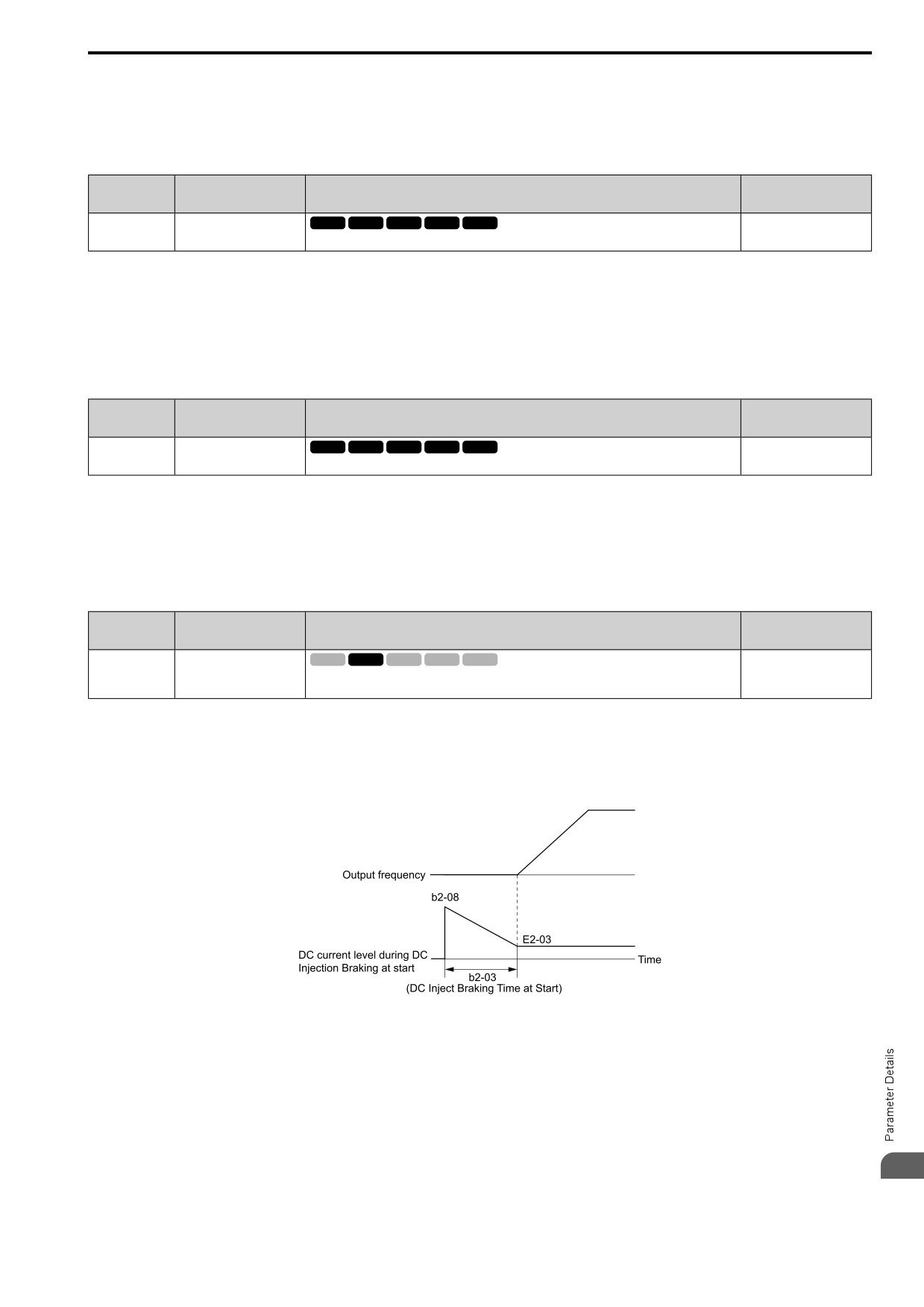
Sets how much current the drive injects when DC Injection Braking at Start starts (Initial
(0 - 1000%)
Excitation) as a percentage of E2-03 [Mot No-Load Current].
This parameter is effective when you start a high-capacity motor (a motor with a large secondary circuit time
constant). This function can quickly increase motor flux to make high starting torque (a process called initial
excitation).
The current level for DC Injection Braking at start changes linearly from the setting of b2-08 to the setting of b2-
03 as shown in Figure 12.21.
Figure 12.21 DC Current Level during DC Injection Braking at Start
Note:
• If b2-08 < 100%, flux will develop very slowly.
• When b2-08 = 0%, the DC current level will be the DC Injection current set in b2-02 [DCI Braking Current].
• If b2-08 is set too high, DC Injection Braking at start can cause a large noise. Adjust b2-08 to decrease the volume to the permitted
level.
12
455
12.2 b: APPLICATION
■ b2-12: SCB Time@Start
No.
Default
Name
Description
(Hex.)
(Range)
b2-12
SCB Time@Start
V/f
OLV OLV/PM AOLV/PM EZOLV
0.00 s
(01BA)
Sets the Short Circuit Braking time at start.
(0.00 - 25.50 s)
This function stops and restarts a coasting PM motor. The drive short circuits all the three motor phases to make
braking torque in the motor.
Set this parameter to 0.00 to disable the function.
Note:
• Short circuit Braking will let external forces rotate the PM motor. Use DC Injection Braking to prevent motor rotation from external
forces.
• Motor speed and load conditions can make it necessary to install a dynamic braking option on the drive.
■ b2-13: SCB Time@Stop
No.
Default
Name
Description
(Hex.)
(Range)
b2-13
SCB Time@Stop
V/f
OLV OLV/PM AOLV/PM EZOLV
A1-02 = 8: 0.00 s
(01BB)
Sets the Short Circuit Braking time at stop.
Other than A1-02 = 8: 0.50
s
(0.00 - 25.50 s)
This function fully stops a PM motor with a large inertia during deceleration and will not let the inertia continue to
rotate the motor.
Short Circuit Braking operates for the time set in b2-13 when output frequency is less than the value set in b2-01
[ZSpd/DCI Threshold] or E1-09 [Min Output Frequency].
Set this parameter to 0.00 to disable the function.
Note:
Motor speed and load conditions can make it necessary to install a dynamic braking option on the drive.
■ b2-18: SCB Current
No.
Default
Name
Description
(Hex.)
(Range)
b2-18
SCB Current
V/f
OLV OLV/PM AOLV/PM EZOLV
100.0%
(0177)
Sets the Short Circuit Braking Current as a percentage of the motor rated current.
(0.0
- 200.0%)
The Short Circuit Braking current cannot be higher than the drive rated current, although a higher current level
can be set using b2-18. The maximum rated current is 120% when the drive is set for Normal Duty (C6-01 = 1
[ND Rating]). The maximum rated current is 150% when the drive is set for Heavy Duty (C6-01 = 0 [HD
Rating]).
◆ b3: SPEED SEARCH
The Speed Search function detects the actual speed of a coasting motor, then restarts the motor before the motor
stops.
Use Speed Search in these conditions:
• To continue operation after momentary power loss
• To switch from commercial power supply to drive power
• To restart a coasting fan
For example, the drive output turns off and the motor coasts when there is a momentary loss of power. After you
return power, the drive does Speed Search on the coasting motor, and restarts the motor from the detected speed.
When you use a PM motor, enable b3-01 [SpSrch@Start Selection].
There are two types of Speed Search for induction motors: Current Detection and Speed Estimation. Use
parameter b3-24 [SpSrch Method Selection] to select the type of Speed Search.
Parameter settings are different for different types of Speed Search. Refer to Table 12.10 for more information.
456
12.2 b: APPLICATION
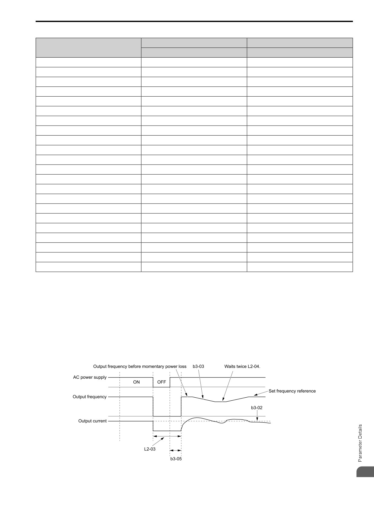
Table
12.10
Speed Search and Related Parameters
Speed Estimation
Current Detection 2
Parameter
b3-24 = 1
b3-24 = 2
b3-01 [SpSrch@Start Selection]
x
x
b3-03 [SpSrch Deceleration Time]
-
x
b3-05 [SpSrch Delay Time]
x
x
b3-06 [Speed Curr Lev1 for Estimation]
x
-
b3-07 [Speed Curr Lev2 for Estimation]
x
-
b3-08 [Speed ACR PGain for Estimation]
x
-
b3-09 [Speed ACR ITime for Estimation]
x
-
b3-10 [Speed Det Gain for Estimation]
x
-
b3-14 [Speed Bi-Directional Search]
x
x
b3-17 [Speed Retry Current Level]
x
x
b3-18 [Speed Retry Delay]
x
x
b3-19 [Speed Retry Times]
x
x
b3-24 [SpSrch Method Selection]
x (1)
x (2)
b3-25 [SpSrch Wait Time]
x
x
b3-26 [Dir. Determ. Level]
x
-
b3-29 [SpSrch BackEMF Threshold]
-
-
b3-31 [SpSrch I Ref Level]
-
x
b3-32 [SpSrch I End Level]
-
x
b3-33 [SpSrch@Uv Selection]
x
x
b3-54 [Search Time]
-
-
b3-55 [Speed Curr Rise Time]
-
-
b3-56 [InverseRotationSearch WaitTime]
-
x
Note:
• To use Speed Estimation Speed Search with V/f Control, do Rotational Auto-Tuning before you set the Speed Search function. If the
wire length between the drive and motor changed since the last time you did Auto-Tuning, do Stationary Auto-Tuning for Line-to-Line
Resistance process again.
• If A1-02 = 5, 6 [PM OLVector, PM AOLVector] and the wiring distance between the motor and drive is long or if the motor is coasting
at more than or equal to 120 Hz, do not use Speed Search to restart the motor. Use Short Circuit Braking.
■ Current Detection 2
Use this Speed Search function with induction motors. Set b3-24 = 2 [SpSrch Method Selection = Current Det2].
Current Detection Speed Search injects current into the motor to detect the speed of an induction motor. Speed
Search increases the output voltage for the time set in L2-04 [Powloss Ramp Time@recovery], starting from the
maximum output frequency or the frequency reference.
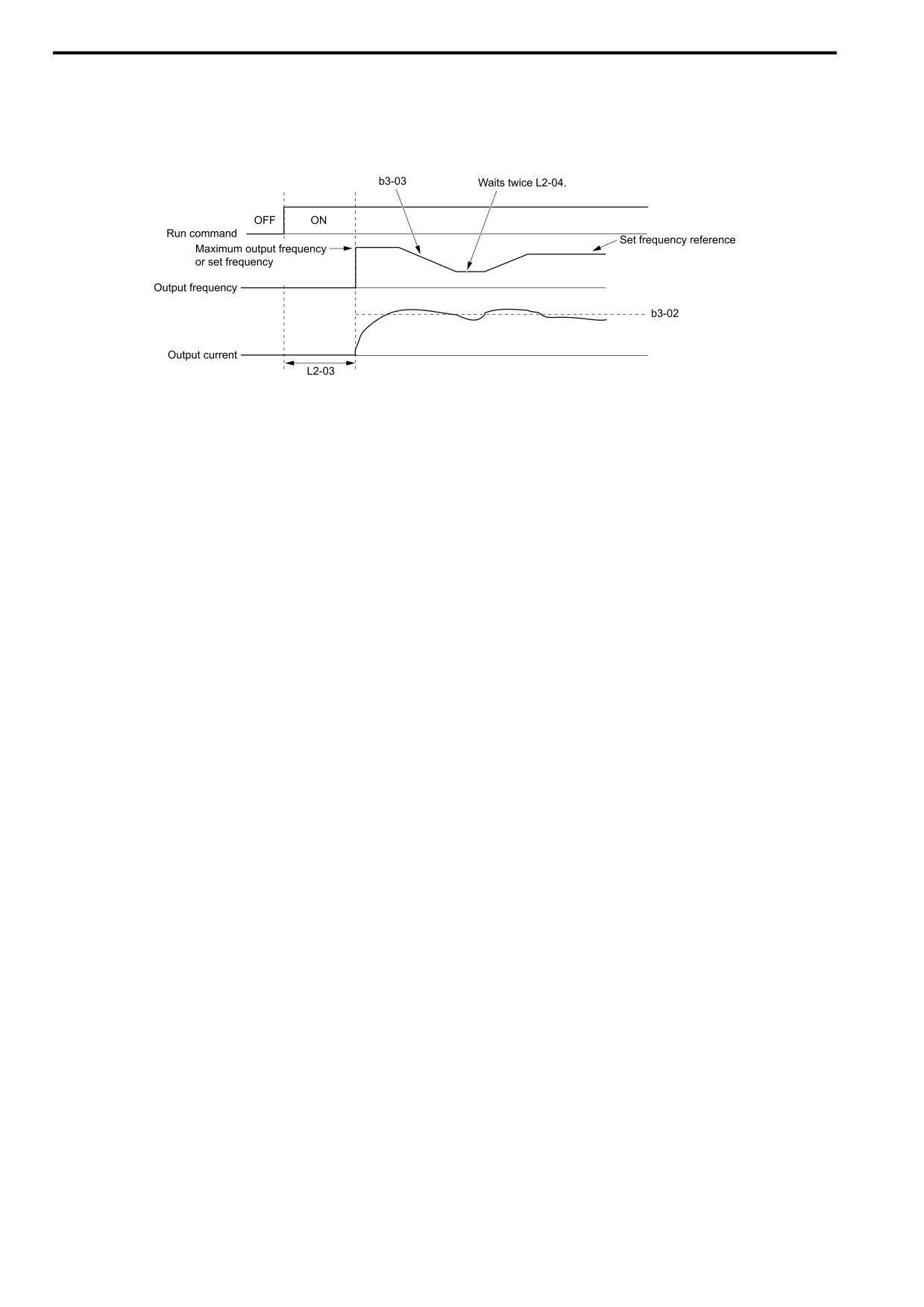
Figure 12.22 Current Detection 2 after Momentary Power Loss
12
457
12.2 b: APPLICATION
Note:
Once power is restored, the drive will not execute Speed Search until the time set in b3-05 [SpSrch Delay Time] has passed. Thus, the
drive will not always start Speed Search although the time set in L2-03 [Min Baseblck Time] is expired.
If you enter the Run command at the same time as Speed Search, the drive will not do Speed Search until the time
set in L2-03 is expired. When the value set in L2-03 < b3-05, the drive will use the wait time set in b3-05.
Figure 12.23 Speed Search Selection at Start (Current Detection Type)
WARNING! Sudden Movement Hazard. Do not do Current Detection Speed Search with light loads or a stopped motor. If you
do Auto-Tuning in these conditions, the motor can suddenly accelerate and cause serious injury or death.
Note:
• You cannot use Current Detection Speed Search with PM motors.
• If the motor is rotating in reverse, you cannot do Speed Search.
• If the drive detects oL1 [Motor Overload] during Current Detection Speed Search, decrease the value set in b3-03.
• If the drive detects oC [Overcurrent] or ov [Overvoltage] during Current Detection Speed Search after the drive recovers from a
momentary power loss, increase the value set in L2-03.
■ Speed Estimation
Use this Speed Search function with induction motors. Set b3-24 = 1 [SpSrch Method Selection = Speed
Estimation]. This function uses less current and has a shorter search time than other functions. This function lets
you do Speed Search when the motor is rotating in reverse. When you return power after a power loss, the motor
will not suddenly accelerate.
Note:
You cannot do Speed Estimation Speed Search in these conditions:
• When You Operate More than One Motor with One Drive
• When you use a high-speed motor (120 Hz or higher)
• When you use a 1.5 kW or smaller motor.
• When the motor output is more than 1 frame size smaller than the drive capacity
• When there is a long wiring distance between the drive and motor
For these conditions, use Current Detection Speed Search.
Speed Estimation Speed Search uses these two steps to estimate the motor speed:
1.
Residual Voltage Search
When there is a short baseblock time, the drive searches for residual voltage. The drive uses the residual
voltage in the motor to estimate the motor speed and direction of rotation. The drive outputs the estimated
motor speed as frequency, then uses the deceleration rate set in L2-04 to increase the voltage. When the output
voltage aligns with the V/f pattern, the drive accelerates or decelerates the motor to the frequency reference. If
the drive cannot estimate the motor speed because of low residual voltage, it will automatically do Current
Injection.
458
12.2 b: APPLICATION
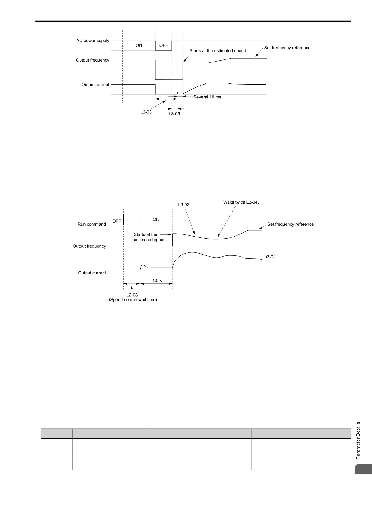
Figure 12.24 Speed Search after Baseblock
Note:
After you return power, the drive waits for the time set in b3-05. If power loss is longer than the time set in L2-03, the drive will start
Speed Search when the time set in b3-05 is expired after the power recovery.
2.
Current Injection
If there is not sufficient residual voltage in the motor, the drive does Current Injection. The drive injects the
quantity of DC current set in b3-06 [Speed Curr Lev1 for Estimation] into the motor windings to estimate the
motor speed and direction of rotation. The drive outputs the estimated motor speed as frequency, then uses the
deceleration rate set in L2-04 to increase the voltage. When the output voltage aligns with the V/f pattern, the
drive accelerates or decelerates the motor to the frequency reference.
Figure 12.25 Speed Search Selection at Start
Note:
Set the lower limit of the delay time to b3-05 for when Speed Search starts.
■ Speed Search and Operation Conditions
These conditions apply to Speed Search operation. When A1-02 = 0, 2 [Control Method = V/f Control,
OLVector], set b3-24 [SpSrch Method Selection] before you do Speed Search.
• Do Speed Search with each Run Command
The drive ignores a Speed Search command from the external terminals.
• Use an MFDI to do an External Speed Search Command
To use an MFDI to do Speed Search, input the Run command at the same time that terminal DIx set for Speed
Search activates, or after Speed Search activates.
Set Speed Search to H1-xx to do the function externally. You cannot set external Speed Search 1 and 2 at the
same time.
Table 12.11 Execute Speed Search via the Digital Input Terminals
H1-xx Setting
Name
Current Detection 2
Speed Estimation
67
SpdSrch Fmax
ON: Speed Search starts from E1-04 [Max Output
Frequency].
External Speed Search commands 1 and 2 work the
same.
68
SpdSrch Fref
ON: Speed Search starts from the frequency reference
The drive estimates the motor speed, then starts Speed
immediately before you input the Speed Search
Search from the estimated speed.
command.
12
• Do Speed Search with Each Auto Restart
459
12.2 b: APPLICATION
Set L5-01 [Auto-Reset Attempts] = 1 or more. After there is an Auto Restart fault, the drive automatically does
Speed Search.
• Do Speed Search after Momentary Power Loss
Set L2-01 =1 [RideThru@PwrLoss = Enabled], and set L2-50 = 0, 1 [RidThruMode@PwrLoss = Timer
Controlled, While CPU Active].
• Do Speed Search after You Clear the External Baseblock Command
After you clear the external baseblock command, enable the Run command, and when the output frequency is
higher than the minimum frequency, the drive does Speed Search.
■ b3-01: SpSrch@Start Selection
No.
Default
Name
Description
(Hex.)
(Range)
b3-01
SpSrch@Start Selection
V/f
OLV OLV/PM AOLV/PM EZOLV
Determined by A1-02
(0191)
Sets the Speed Search at Start function where the drive will perform Speed Search with each Run
(0, 1)
command.
0 : Disabled
Enter a Run command to start to operate the drive at the minimum output frequency.
When the Run command is enabled and the Speed Search from Fmax or Fref [H1-xx = 67, 68] is input from a
multi-function input terminal, the drive will do Speed Search and start to operate the motor.
1 : Enabled
Enter the Run command to do Speed Search. The drive completes Speed Search then starts to operate the motor.
■ b3-02: SpSrch Deactivation Current
No.
Default
Name
Description
(Hex.)
(Range)
b3-02
SpSrch Deactivation
V/f
OLV OLV/PM AOLV/PM EZOLV
Determined by A1-02
Current
(0192)
Sets the current level that stops Speed Search as a percentage of the drive rated output current.
(0 - 200%)
Usually it is not necessary to change this setting.
If the drive cannot restart the motor, decrease this setting.
■ b3-03: SpSrch Deceleration Time
No.
Default
Name
Description
(Hex.)
(Range)
b3-03
SpSrch Deceleration Time
V/f
OLV OLV/PM AOLV/PM EZOLV
2.0 s
(0193)
Sets the deceleration time during Speed Search operation. Set the length of time to decelerate
(0.1 - 10.0 s)
from the maximum output frequency to the minimum output frequency.
This is the output frequency deceleration time used by Current Detection Speed Search and by the Current
Injection Method of Speed Estimation Speed Search.
Note:
• When A1-02 = 8 [Control Method = EZ Vector], this parameter takes effect only in Expert Mode.
• If the drive detects oL1 [Motor Overload] during Current Detection Speed Search, decrease the value set in b3-03.
■ b3-04: SpSrch V/F Gain
No.
Default
Name
Description
(Hex.)
(Range)
V/f
OLV OLV/PM AOLV/PM EZOLV
b3-04
SpSrch V/F Gain
Determined by o2-04
(0194)
Sets the ratio used to reduce the V/f during searches to reduce the output current during speed
(10 - 100)
searches.
Use the this formula to calculate the output voltage during Speed Search:
Output voltage during Speed Search = Configured V/f × b3-04
When the current detection search operates correctly, this configuration is not necessary.
■ b3-05: SpSrch Delay Time
No.
Default
Name
Description
(Hex.)
(Range)
b3-05
SpSrch Delay Time
V/f
OLV OLV/PM AOLV/PM EZOLV
0.2 s
(0195)
Sets the Speed Search delay time to activate a magnetic contactor installed between the drive and
(0.0 - 100.0 s)
motor.
460
12.2 b: APPLICATION
When you use a magnetic contactor between the drive and motor, you must close the contactor before the drive
will do Speed Search. This parameter sets a delay time to activate the magnetic contactor.
■ b3-06: Speed Curr Lev1 for Estimation
No.
Default
Name
Description
(Hex.)
(Range)
b3-06
Speed Curr Lev1 for
V/f
OLV OLV/PM AOLV/PM EZOLV
Determined by o2-04
Estimation
(0196)
Sets the level of current that flows to the motor during Speed Estimation Speed Search as a
(0.0
- 2.0)
coefficient of the motor rated current. Usually it is not necessary to change this setting.
Expert
When the speed estimation value is the minimum output frequency, increase this setting. You can do this when the
motor coasts at a high speed while the drive estimates the speed during Speed Estimation Speed Search. The limit
of the output current during speed search is automatically the drive rated current.
Note:
When the drive cannot accurately estimate the speed after you adjust this parameter, use Current Detection Speed Search.
■ b3-07: Speed Curr Lev2 for Estimation
No.
Default
Name
Description
(Hex.)
(Range)
V/f
OLV OLV/PM AOLV/PM EZOLV
b3-07
Speed Curr Lev2 for
1.0
Estimation
(0197)
Sets the level of current that flows to the motor during Speed Estimation Speed Search as a
(0.0
- 3.0)
coefficient of E2-03 [Mot No-Load Current] or E4-03 [M2 No-Load Current]. Usually it is not
Expert
necessary to change this setting.
During Speed Estimation Speed Searches, when the speed estimation value aligns with the minimum output
frequency, increase the setting value in 0.1-unit increments. The limit of the output current during speed search is
automatically the drive rated current.
■ b3-08: Speed ACR PGain for Estimation
No.
Default
Name
Description
(Hex.)
(Range)
b3-08
Speed ACR PGain for
V/f
OLV OLV/PM AOLV/PM EZOLV
Determined by A1-02 and
Estimation
o2-04
(0198)
Sets the proportional gain for the automatic current regulator during Speed Estimation Speed
Search. Also adjusts speed search responsiveness. Usually it is not necessary to change this
(0.00
- 6.00)
Expert
setting.
■ b3-09: Speed ACR ITime for Estimation
No.
Default
Name
Description
(Hex.)
(Range)
V/f
OLV OLV/PM AOLV/PM EZOLV
b3-09
Speed ACR ITime for
Determined by A1-02
Estimation
(0199)
Sets the integral time for the automatic current regulator during Speed Estimation Speed Search.
(0.0 - 1000.0 ms)
Also adjusts speed search responsiveness. Usually it is not necessary to change this setting.
Expert
■ b3-10: Speed Det Gain for Estimation
No.
Default
Name
Description
(Hex.)
(Range)
b3-10
Speed Det Gain for
V/f
OLV OLV/PM AOLV/PM EZOLV
1.05
Estimation
(019A)
Sets the gain to correct estimated frequencies from Speed Estimation Speed Search.
(1.00
- 1.20)
Expert
If the drive detects ov [DC Bus Overvoltage] when you restart the motor, increase the setting value.
■ b3-14: Speed Bi-Directional Search
No.
Default
Name
Description
(Hex.)
(Range)
V/f
OLV OLV/PM AOLV/PM EZOLV
b3-14
Speed Bi-Directional
Determined by A1-02 and
Search
b3-24
(019E)
Sets the direction of Speed Search to the direction of the frequency reference or in the motor
rotation direction as detected by the drive.
(0, 1)
12
461
12.2 b: APPLICATION
Note:
• When E9-01 = 0 [Motor Type Selection = Induction (IM)] and A1-02 = 0, 2, or 8 [Control Method Selection = V/f, OLV, or EZOLV],
the default settings change when the setting of b3-24 [Speed Search Method Selection] changes.
-b3-24 = 1 [Speed Estimation]: Refer to Parameters that Change from the Default Settings with A1-02 [Control Method] on page 403.
-b3-24 = 2 [Current Detection 2]: 0
• When E9-01 = 1 or 2 [Permanent Magnet (PM), Synchronous Reluctance (SynRM)] and A1-02 = 0 or 8 [V/f, EZOLV], refer to
Parameters that Change from the Default Settings with A1-02 [Control Method] on page 403.
When you set A1-02, b3-24, and E9-01, set b3-14.
0 : Disabled
The drive uses the frequency reference to detect the direction of motor rotation.
1 : Enabled
The drive detects the direction of motor rotation during Speed Search.
■ b3-17: Speed Retry Current Level
No.
Default
Name
Description
(Hex.)
(Range)
V/f
OLV OLV/PM AOLV/PM EZOLV
b3-17
Speed Retry Current Level
150%
(01F0)
Sets the current level for the search retry function in Speed Estimation Speed Search as a
(0 - 200%)
percentage where drive rated current is a setting value of 100%.
Expert
When a large quantity of current flows during Speed Estimation Speed Search, the drive temporarily stops
operation to prevent overvoltage and overcurrent. When the current is at the level set in b3-17, the drive tries
speed search again.
■ b3-18: Speed Retry Delay
No.
Default
Name
Description
(Hex.)
(Range)
b3-18
Speed Retry Delay
V/f
OLV OLV/PM AOLV/PM EZOLV
0.10 s
(01F1)
Sets the length of time that the drive will wait to retry Speed Estimation Speed Search when too
(0.00 - 1.00 s)
much current flow stopped the Speed Search.
Expert
When the current is more than the level set in b3-17 [Speed Retry Current Level] during the time set in b3-18, the
drive tries speed search again.
■ b3-19: Speed Retry Times
No.
Default
Name
Description
(Hex.)
(Range)
b3-19
Speed Retry Times
V/f
OLV OLV/PM AOLV/PM EZOLV
3 times
(01F2)
Sets the number of times to restart Speed Search if Speed Search does not complete.
(0 - 10 times)
If the drive does the number of Speed Search restarts set in this parameter, it will trigger an SEr [Speed Search
Retries Exceeded] error.
■ b3-24: SpSrch Method Selection
No.
Default
Name
Description
(Hex.)
(Range)
b3-24
SpSrch Method Selection
V/f
OLV OLV/PM AOLV/PM EZOLV
2
(01C0)
Sets the Speed Search method when you start the motor or when you restore power after a
(1, 2)
momentary power loss.
Note:
• When A1-02 = 8 [Control Method = EZ Vector], the default setting changes when the setting for E9-01 [Motor Type Selection]
changes.
- E9-01 = 0 [IM]: 2
- E9-01 = 1, 2 [PM, SynRM]: 1
• When you set b3-24, it will trigger the drive to initialize b3-14 [Speed Bi-Directional Search]. After you set b3-24, set b3-14.
Set b3-01 = 1 [SpSrch@Start Selection = Enabled] to do Speed Search at start. Set L2-01 = 1
[RideThru@PwrLoss = Enabled]] to do Speed Search after you restore power after a momentary power loss.
1 : Speed Estimation
The drive uses the residual voltage from a short baseblock time to estimate the motor speed.
462
12.2 b: APPLICATION
If there is not sufficient residual voltage, then the drive will inject DC current into the motor to estimate the motor
speed.
2 : Current Det2
The drive will inject DC current into the motor to estimate motor speed.
■ b3-25: SpSrch Wait Time
No.
Default
Name
Description
(Hex.)
(Range)
b3-25
SpSrch Wait Time
V/f
OLV OLV/PM AOLV/PM EZOLV
0.5 s
(01C8)
Sets the length of time the drive will wait to start the Speed Search Retry function.
(0.0 - 30.0 s)
Expert
If the drive detects these faults during speed search, increase the setting value:
• oC [Overcurrent]
• ov [Overvoltage]
• SEr [Speed Search Retries Exceeded]
■ b3-26: Dir. Determ. Level
No.
Default
Name
Description
(Hex.)
(Range)
b3-26
Dir. Determ. Level
V/f
OLV OLV/PM AOLV/PM EZOLV
1000
(01C7)
Sets the level to find the motor rotation direction. Increase the value if the drive cannot find the
(40 to 60000)
direction.
Expert
■ b3-29: SpSrch BackEMF Threshold
No.
Default
Name
Description
(Hex.)
(Range)
b3-29
SpSrch BackEMF
V/f
OLV OLV/PM AOLV/PM EZOLV
10%
Threshold
(077C)
Sets the induced voltage for motors that use Speed Search. The drive will start Speed Search
(0 - 10%)
when the motor induced voltage level is the same as the setting value. Usually it is not necessary
Expert
to change this setting.
To make adjustments, gradually decrease the setting value. If you decrease the setting value too much, speed
search will not operate correctly.
■ b3-31: SpSrch I Ref Level
No.
Default
Name
Description
(Hex.)
(Range)
b3-31
SpSrch I Ref Level
V/f
OLV OLV/PM AOLV/PM EZOLV
1.50
(0BC0)
Sets the current level that decreases the output current during Current Detection Speed Search.
(1.50
- 3.50)
Expert
Set this parameter as a ratio of E2-03 [Mot No-Load Current]. The setting is a ratio with respect to 30% of the
motor rated current when E2-03 ≤ E2-01 [Mot Rated Current (FLA)] × 0.3.
Note:
The setting is a ratio with respect to E9-06 [Motor Rated Current] × 0.5 when A1-02 = 8 [Control Method = EZ Vector].
■ b3-32: SpSrch I End Level
No.
Default
Name
Description
(Hex.)
(Range)
b3-32
SpSrch I End Level
V/f
OLV OLV/PM AOLV/PM EZOLV
1.20
(0BC1)
Sets the current level that completes Speed Search.
(0.00
- 1.49)
Expert
The Current Detection Speed Search gradually decreases the output frequency to search for the motor speed when
the output current is equal to or less than Speed Search Current Complete Level.
Set this parameter as a ratio of E2-03 [Mot No-Load Current]. The setting is a ratio with respect to 30% of the
motor rated current when E2-03 ≤ E2-01 [Mot Rated Current (FLA)] × 0.3.
12
Note:
The setting is a ratio with respect to E9-06 [Motor Rated Current] × 0.5 when A1-02 = 8 [Control Method = EZ Vector].
463
12.2 b: APPLICATION
■ b3-33: SpSrch@Uv Selection
No.
Default
Name
Description
(Hex.)
(Range)
b3-33
SpSrch@Uv Selection
V/f
OLV OLV/PM AOLV/PM EZOLV
1
(0B3F)
Sets the function that starts Speed Search at start-up if the drive detects a Uv [Undervoltage]
(0, 1)
when it receives a Run command.
Expert
Set these three parameters as shown to enable b3-33:
• L2-01 = 1, 2 [RideThru@PwrLoss = Enabled]
• L2-50 = 0, 1 [RidThruMode@PwrLoss = Timer Controlled, While CPU Active]
• b3-01 = 1 [SpSrch@Start Selection = Enabled]
• b1-03 = 1 [Stopping Method Selection = Coast->Stop]
0 : Disabled
1 : Enabled
■ b3-54: Search Time
No.
Default
Name
Description
(Hex.)
(Range)
V/f
OLV OLV/PM AOLV/PM EZOLV
b3-54
Search Time
400 ms
(3123)
Sets the length of time that the drive will run Speed Search.
(10 - 2000 ms)
If you set this parameter too low, Speed Search will not operate correctly.
If the drive detects oC [Overcurrent] immediately after Speed Search Starts:
• Increase the value of L2-03 [Min Baseblck Time] and decrease the motor speed you use to start Speed Search.
• Increases the setting value of b3-08 [Speed ACR PGain for Estimation].
• Increase the value of b3-54.
If the drive detects oC or ov [DC Bus Overvoltage] during Speed Search, increase the value of b3-08.
■ b3-55: Speed Curr Rise Time
No.
Default
Name
Description
(Hex.)
(Range)
b3-55
Speed Curr Rise Time
V/f
OLV OLV/PM AOLV/PM EZOLV
10 ms
(3124)
Sets the length of time that the drive will increase the current from zero current to the setting
(10 - 2000 ms)
value of b3-06 [Speed Curr Lev1 for Estimation].
Expert
Gradually increase the setting value when a large quantity of current flows after speed search starts. If you set this
value too high, speed search will not operate correctly.
■ b3-56: InverseRotationSearch WaitTime
No.
Default
Name
Description
(Hex.)
(Range)
b3-56
InverseRotationSearch
V/f
OLV OLV/PM AOLV/PM EZOLV
Determined by o2-04
WaitTime
(3126)
Sets the wait time until the drive starts inverse rotation search after it completes forward search
(0.1 - 5.0 s)
when you do inverse rotation search during Current Detection Speed Search.
■ b3-61: Magn Pole Find Gain
No.
Default
Name
Description
(Hex.)
(Range)
b3-61
Magn Pole Find Gain
V/f
OLV OLV/PM AOLV/PM EZOLV
5.0
(1B96)
Sets the responsiveness for initial motor magnetic pole calculation when A1-02 = 6 [Control
(-20.0 - +20.0)
Method = PM AOLVector]. Set b3-61 > 0.0 for an ordinary IPM motor.
Expert
Used when n8-35 = 2 [InitRotorPos Selection = HiFreq Injection]. Sets the responsiveness for initial motor
magnetic pole calculation. Set this parameter to a positive value for an ordinary monitor. When you use High
Frequency injection Tuning, it will automatically set this parameter.
◆ b4: TIMER
The drive uses timers to delay activating and deactivating MFDO terminals.
464
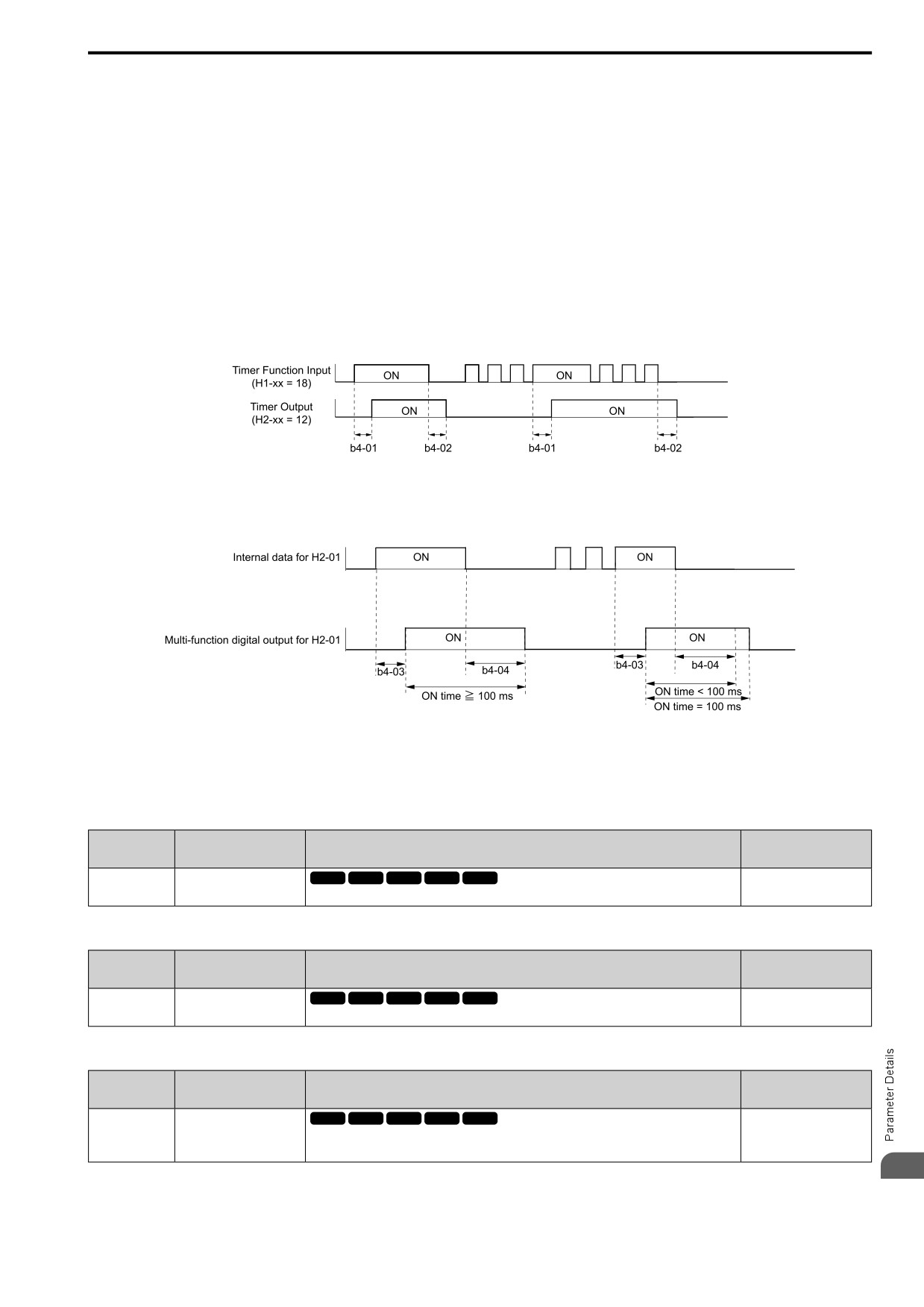
12.2 b: APPLICATION
Timers prevent sensors and switches from making chattering noise.
There are two types of timers:
• Timers that set a delay for timer inputs and timer outputs.
These timers delay activating and deactivating of the MFDIs and MFDOs.
To enable this function, set H1-xx = 60 [MFDI Function Select = Timer Fn Input], and set H2-01 to H2-03 =
39 [MFDO Function Select = Timer Output].
• Timers that set a delay to activate and deactivate MFDO terminals.
These timers delay activating and deactivating MFDO terminals.
To enable this function, set delay times in parameters b4-03 to b4-08.
■ Timer Function Operation
• Timers that Set a Delay for Timer Inputs and Timer Outputs
Triggers timer output if the timer input is active for longer than the time set in b4-01 [Timer Function ON-Delay
Time]. Triggers timer output late for the time set in b4-02 [Timer Function OFF-Delay Time]. Figure 12.26
shows an example of how the timer function works.
Figure 12.26 Example of Timer Function Operation
• Setting On/Off-delay Time for MFDO
Figure 12.27 uses H2-01 terminals to show an example of how the timer function works. Use b4-03 [Terminal
M1-M2 ON-Delay Time] and b4-04 [Terminal M1-M2 OFF-Delay Time] to set this function.
Figure 12.27 Example of How the Timer Function Works with H2-01 Terminals
Note:
When the terminal is triggered, it continues for a minimum of 100 ms. The on/off-delay time of MFDO terminal does not have an effect.
■ b4-01: Timer ON Time Delay
No.
Default
Name
Description
(Hex.)
(Range)
b4-01
Timer ON Time Delay
V/f
OLV OLV/PM AOLV/PM EZOLV
0.0 s
(01A3)
Sets the ON-delay time for the timer input.
(0.0 - 3000.0 s)
■ b4-02: Timer OFF Time Delay
No.
Default
Name
Description
(Hex.)
(Range)
b4-02
Timer OFF Time Delay
V/f
OLV OLV/PM AOLV/PM EZOLV
0.0 s
(01A4)
Sets the OFF-delay time for the timer input.
(0.0 - 3000.0 s)
■ b4-03: NO,NC,CM ON-Time Delay
No.
Default
Name
Description
(Hex.)
(Range)
b4-03
NO,NC,CM ON-Time
V/f
OLV OLV/PM AOLV/PM EZOLV
0 ms
Delay
(0B30)
Sets the delay time until the contact is turned ON after the function set with H2-01 turns ON.
(0 - 65000 ms)
Expert
12
465
12.2 b: APPLICATION
■ b4-04: NO,NC,CM OFF-Time Delay
No.
Default
Name
Description
(Hex.)
(Range)
b4-04
NO,NC,CM OFF-Time
V/f
OLV OLV/PM AOLV/PM EZOLV
0 ms
Delay
(0B31)
Sets the delay time to deactivate the contact after the function set in H2-01 deactivates.
(0
- 65000 ms)
Expert
■ b4-05: DO1 ON-Time Delay
No.
Default
Name
Description
(Hex.)
(Range)
b4-05
DO1 ON-Time Delay
V/f
OLV OLV/PM AOLV/PM EZOLV
0 ms
(0B32)
Sets the delay time to activate the contact after the function set in H2-02 activates.
(0
- 65000 ms)
Expert
■ b4-06: DO1 OFF-Time Delay
No.
Default
Name
Description
(Hex.)
(Range)
b4-06
DO1 OFF-Time Delay
V/f
OLV OLV/PM AOLV/PM EZOLV
0 ms
(0B33)
Sets the delay time to deactivate the contact after the function set in H2-02 deactivates.
(0
- 65000 ms)
Expert
■ b4-07: DO2 ON-Time Delay
No.
Default
Name
Description
(Hex.)
(Range)
b4-07
DO2 ON-Time Delay
V/f
OLV OLV/PM AOLV/PM EZOLV
0 ms
(0B34)
Sets the delay time until the contact is turned ON after the function set with H2-03 turns ON.
(0
- 65000 ms)
Expert
■ b4-08: DO2 OFF-Time Delay
No.
Default
Name
Description
(Hex.)
(Range)
V/f
OLV OLV/PM AOLV/PM EZOLV
b4-08
DO2 OFF-Time Delay
0 ms
(0B35)
Sets the delay time to deactivate the contact after the function set in H2-03 deactivates.
(0
- 65000 ms)
Expert
◆ b5: PID CONTROL
The drive has a PID control function. You can control drive output to adjust the proportional gain, integral time,
and derivative time that has an effect on the bias between the target value and the feedback value to match the
target value to the detected value. Use this function to adjust the drive output to accurately match the flow,
pressure, and temperature in the application match the target value.
Use a combination of these controls to increase the performance:
• P control
P control has a proportional effect on the deviation. It outputs the product (the controlled output) proportional to
the deviation. You cannot use only the offset from P control to get to zero deviation.
• I control
I control is the integral of the deviation. It uses an integral value of the deviation to output the product (the
controlled output). I control helps align the feedback value and the target value. If you use only a proportional
effect (P control), it will cause and offset. Use a proportional effect with integral control, and the offset will
disappear over time.
• D control
D control is the derivative of the deviation. D control has an effect on drive output when there are sudden, large
changes in the deviation or feedback value. It quickly returns drive output to the value before the sudden
change. It multiplies a time constant by a derivative value of the deviation (slope of the deviation), and adds that
result to PID input to calculate the deviation of the signal, then it corrects the deviation.
Note:
D control has causes less stable operation because the noise changes the deviation signal. Use D control only when necessary.
466
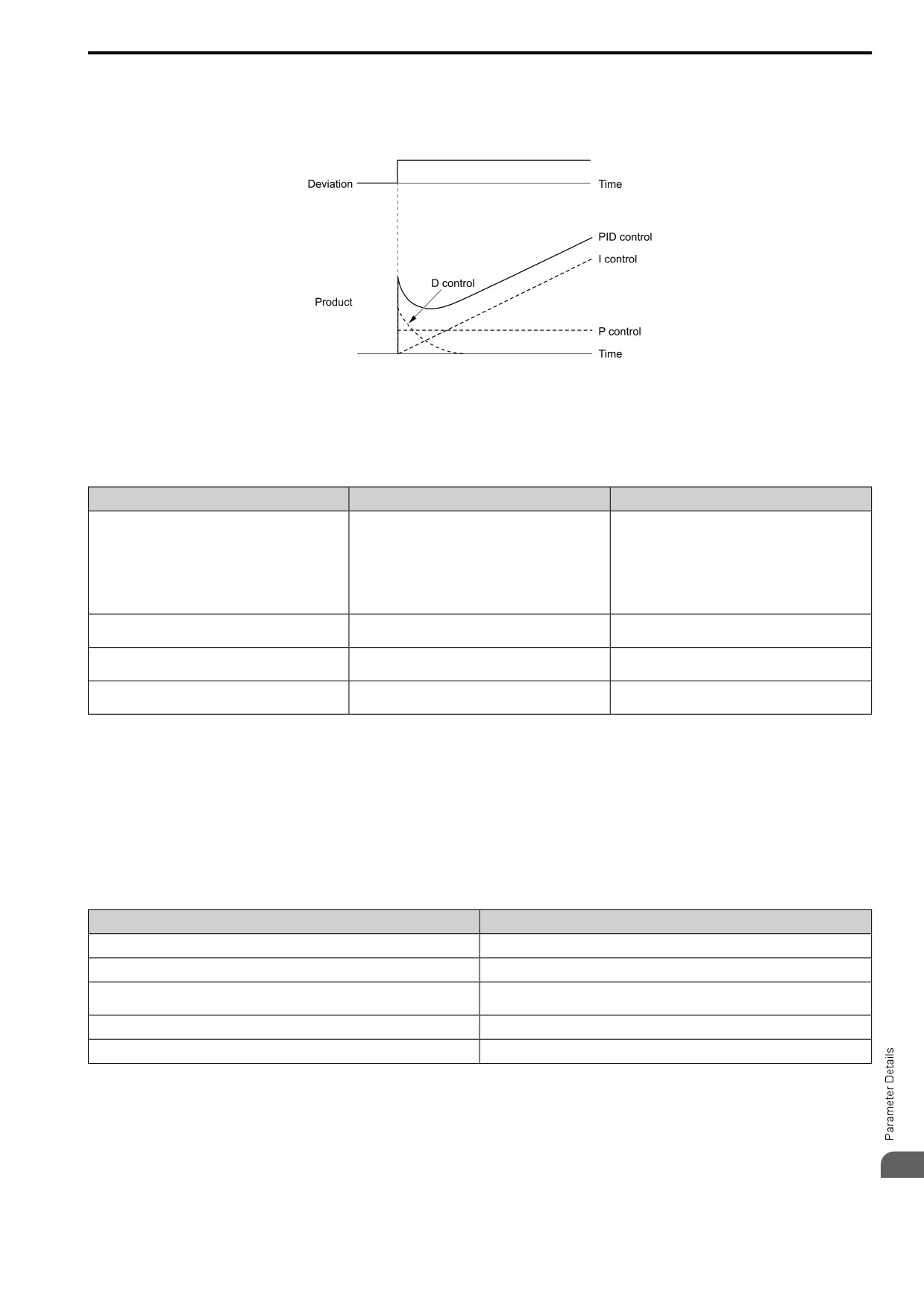
12.2 b: APPLICATION
■ PID Control Operation
This figure shows PID control operation. The modified output (output frequency) changes when the drive uses
PID control to keep the deviation (the difference between the target value and the feedback value) constant.
Figure 12.28 PID Control Operation
■ PID Control Applications
This table shows applications for PID control.
Table 12.12 PID Control Applications
Application
Control Content
Sensors Used
Speed Control
• The drive uses a feedback signal for the machine
Tacho generator
speed, and adjusts that speed to align with the target
value.
• The drive uses speed data from other machinery as the
target value to do synchronous control. The drive then
adds that target value to the feedback from the
machine it is operating to align its speed with the other
machinery.
Pressure control
The drive uses feedback from the actual pressure to hold
Pressure sensor
constant pressure.
Flow control
The drive uses feedback from the actual flow to hold
Flow rate sensor
constant flow.
Temperature control
The drive uses feedback from the actual temperature to
Thermocoupler, thermistor
control a fan and hold constant temperature.
■ Input Methods for the PID Setpoint
Use b5-01 = 1 [PID Enable = Enabled] and b5-70 to b5-72 to select how the PID setpoint is input to the drive.
When b5-70 = 0 [PID MainRefMode = PID only] or b5-70 = 1 [Fref + PID] and b5-72 = 0 [PID D-FF Mode =
D=Fdback], either the frequency reference set in b1-01 [Freq. Ref. Sel. 1] or b1-15 [Freq. Ref. Sel. 2] will be the
PID setpoint, or the one of the inputs in Table 12.13 will be the PID setpoint.
When b5-70 = 1 [Fref + PID] or b5-70 = 1 [Fref + PID] and b5-72 = 1 [D=Fdback], one of the inputs in Table
12.13 will be the PID setpoint.
Table 12.13 Input Methods for the PID Setpoint
Input Methods for the PID Setpoint
Setting Value
MFAI terminal AI1
Set H3-02 = 10 [AI1 Function Selection = PID SetPoint].
MFAI terminal AI2
Set H3-10 [AI2 Function Selection] = 10.
Modbus register 0006H
Sets Modbus register 000FH (Control Selection Setting) bit 1 to 1 (PID setpoint input).
Enters the PID setpoint to Modbus register 0006H (PID Target, 0.01% units, signed).
Pulse train input terminal DI
Set H6-01 = 2 [PI Pulse Train Function = PID SP Value].
b5-19 [PID Setpoint Value]
Set b5-18 = 1 [b5-19 PID SP Selection = Enabled]. Enters the PID setpoint to b5-19.
Note:
If you set two inputs for the PID setpoint, it will trigger operation error oPE07 [Analog Input Selection Error].
■ Entering the PID Feedback Value
You can use two methods to input the PID feedback value to the drive. One method uses a single feedback signal
12
for usual PID control. The other method uses two signals. The difference between those signals sets the deviation.
• Use a single feedback signal.
467
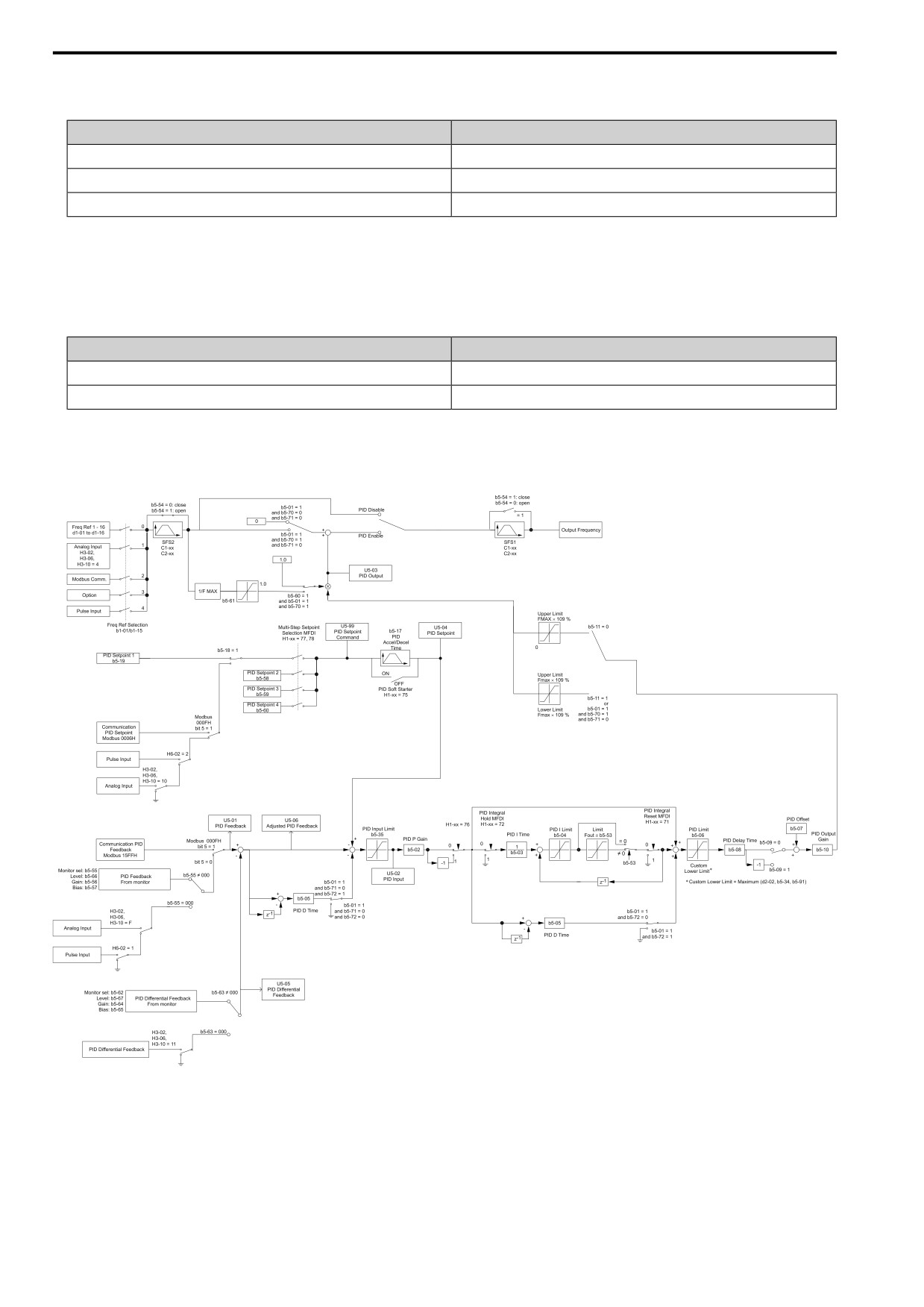
12.2 b: APPLICATION
Use Table 12.14 to select how the feedback signal is input to the drive for PID control.
Table 12.14 PID Feedback Input Method
PID Feedback Input Method
Setting Value
MFAI terminal AI1
Set H3-02 = F [PID Fbk].
MFAI terminal AI2
Set H3-10 = F.
Pulse train input terminal DI
Set H6-01 = 1 [PIDFbk Value].
• Use two signals, and use the difference between those signals as the feedback signal.
The drive uses two feedback signals, and the difference between those signals becomes the deviation.
Use Table 12.15 to select how the second feedback value is input to the drive. The drive calculates the deviation
of the second feedback value. Set H3-02 or H3-10 = 11 [AI1 Function Selection or AI2 Function Selection =
Diff PIDFbk] to enable the second feedback signal used to calculated the deviation.
Table 12.15 PID Differential Feedback Input Method
PID Differential Feedback Input Method
Setting Value
MFAI terminal AI1
Set H3-02 = 11 [Diff PIDFbk].
MFAI terminal AI2
Set H3-10 = 11.
Note:
If you set H3-02 and H3-10 = 11, it will trigger oPE07 [Analog Input Selection Error].
■ PID Control Block Diagram
Figure 12.29 PID Control Block Diagram
■ PID Feedback Loss Detection
The PID feedback loss detection function detects broken sensors and defective wiring between the drive and
sensors.
468
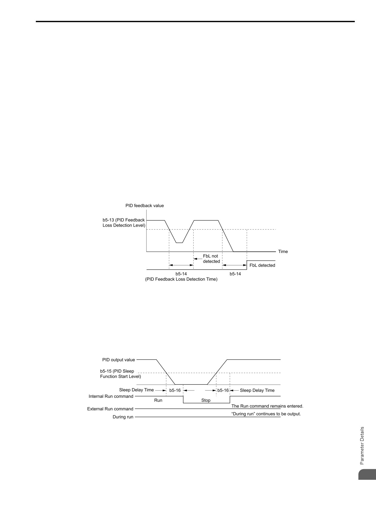
12.2 b: APPLICATION
Use the PID feedback loss detection function when you use PID control. If the feedback signal is too low, the
motor can suddenly accelerate to the maximum output frequency. This function prevents such risks to the load.
The drive uses two methods to detect feedback loss:
• PID Feedback Loss [FbL]
Set these parameters for the PID feedback loss detection function.
The drive detects feedback loss when the feedback value is less than the value in b5-13 for longer than the time
in b5-14.
- b5-12 [Fdback Loss Select Mode]
- b5-13 [Fdback Loss Lvl]
- b5-14 [Fdback Loss Time]
• Excessive PID Feedback [FbH]
Set these parameters to set how the drive detects a feedback level that is too high.
The drive detects too much PID feedback when the feedback value is more than the value in b5-36 for longer
than the time in b5-37.
- b5-12 [Fdback Loss Select Mode]
- b5-36 [PID HiHi Limit Level]
- b5-37 [PID HiHi Time]
This figure shows the operation principle when the feedback value is too low, and the drive detects feedback loss.
The operation is the same when the drive detects too much feedback.
Figure 12.30 Time Chart for PID Feedback Loss Detection Time
■ PID Sleep
PID sleep stops drive operation when the PID output or the frequency reference is less than b5-15 [Sleep Start
Level]. This function shuts off drive output after the motor decelerates to the set frequency.
The drive will automatically restart the motor when the PID output or the frequency reference is more than the b5-
15 value for the time set in b5-16 [Sleep Delay Time].
This figure shows the PID Sleep function.
Figure 12.31 PID Sleep Time Chart
Note:
• The PID Sleep function is enabled when PID control is disabled.
• When the PID Sleep function is triggered, the drive will stop the motor as specified by b1-03 [Stopping Method Selection].
■ Fine-Tuning PID
12
Fine-tune the following parameter settings to have PID control eliminate problems with overshoot and oscillation.
• b5-02 [Proportional Gain (P)]
469
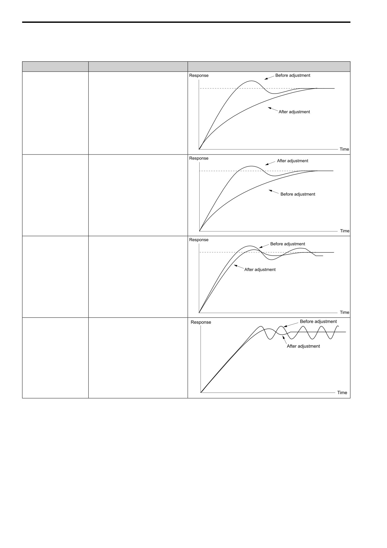
12.2 b: APPLICATION
• b5-03 [Integral Time (I)]
• b5-05 [Derivative Time (D)]
• b5-08 [PID Primary Delay Time Constant]
Purpose
Procedure
Results
Prevent overshoot.
• Set b5-05 [Derivative Time (D)] to a smaller
value.
• Set b5-03 [Integral Time (I)] to a larger value.
Quickly stabilize control.
• Set b5-05 [Derivative Time (D)] to a larger
value.
• Set b5-03 [Integral Time (I)] to a smaller value.
Prevent long-cycle oscillations.
Set b5-03 [Integral Time (I)] to a larger value.
Prevent short-cycle oscillations.
• Set b5-05 [Derivative Time (D)] to a smaller
value.
• If you set b5-05 = 0.00 [Derivative Time (D) =
disabling D control] and it does not stop
oscillation, then set b5-02 [Proportional Gain
(P)] to a smaller value or set b5-08 [PID
Primary Delay Time Constant] to a larger value.
■ EZ Sleep/Wake-up Functionality
Set b5-89 = 1 [Sleep Method Selection = EZ Sleep/Wake-up] to enable the EZ Sleep/Wake-up function.
Note:
• When b5-89 = 0 [Sleep Method Selection = Standard], the EZ Sleep function and related parameters are disabled. Parameter b5-91
[EZsleep Min Spd] is not included in this rule.
• Set b5-89 = 1 to disable b5-15 [Sleep Start Level].
470
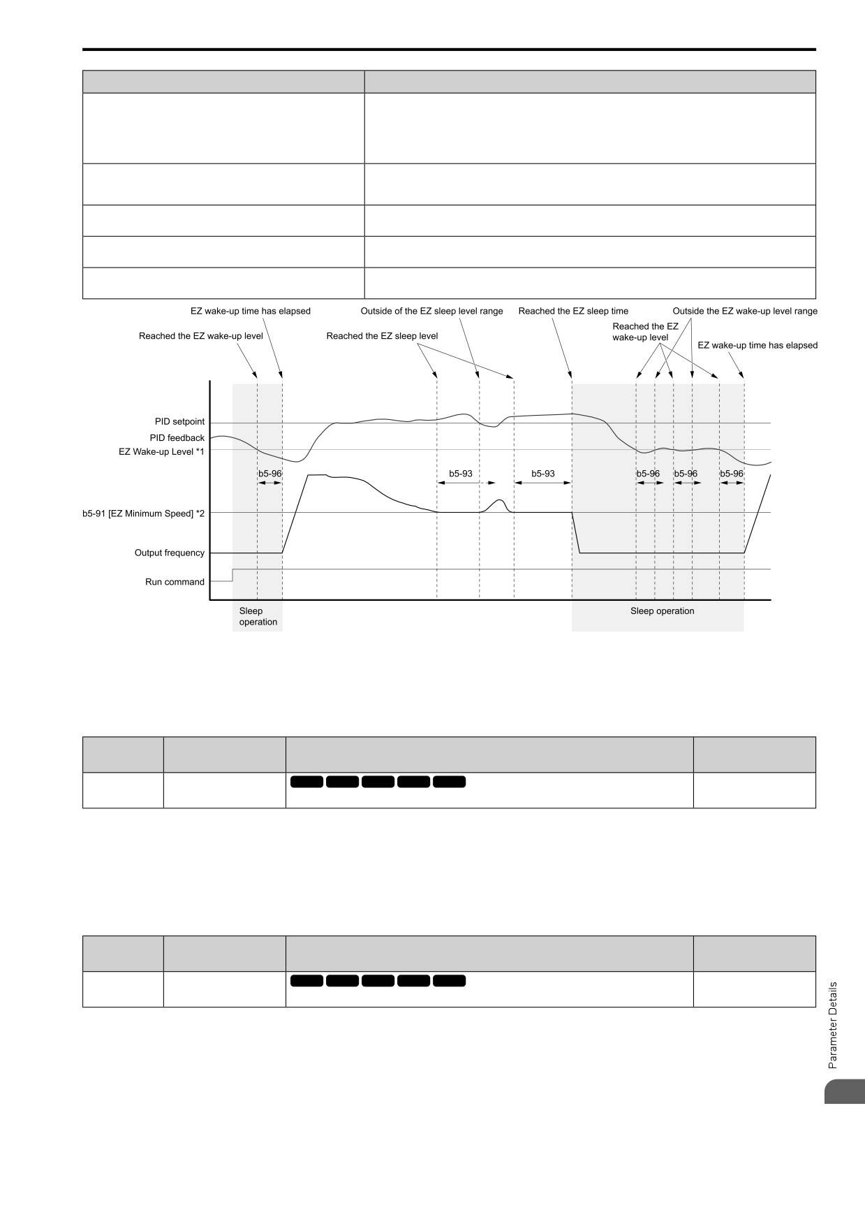
12.2 b: APPLICATION
Configuration Parameter
Description
b5-90 [EZsleep Unit]
Sets the unit of measure for b5-92 [EZsleep Level]. When b5-90 = 1 [0.1Hz units], the setting range of b5-
91 [EZsleep Min Spd] is 0.0 to 590.0 Hz. When b5-90 = 0 [rpm], the setting range is 0 to 35400 min-1 (r/
min).
Note:
When you change b5-90, the value of b5-92 is not automatically updated.
b5-91 [EZsleep Min Spd]
This parameter sets the lower limit for PID output. The drive uses the largest value of b5-91, b5-34 [PID Out
Low Limit Level], and d2-02 [FRef Lower Limit] to internally set the lower limit of PID output. The b5-89
setting does not have an effect.
b5-92 [EZsleep Level]
When the output frequency or motor speed is less than the value of b5-92 for longer than the value of b5-93
[EZsleep Time], the drive does to sleep.
b5-95 = 1 [EZsleep Wake Mode = Absolute]
When the PID feedback is less than the value of b5-94 [EZsleep Wake Level] for longer than the time set in
b5-96 [EZsleep Wake Time], the drive restarts operation from sleep.
b5-95 = 0 [EZsleep Wake Mode = Setpoint Delta]
When the PID feedback is less than the value set as the PID setpoint value minus b5-94 for the time set in
b5-96, the drive restarts operation from sleep.
Figure 12.32 EZ Sleep/Wake-up Operation: PID Output is Normal and b5-92 = 0.0 Hz
*1
The values of b5-94 and b5-95 set operation.
*2
In the example, b5-92 is at the default setting of 0.0 Hz. b5-91 is the EZ sleep level.
■ b5-01: PID Enable
No.
Default
Name
Description
(Hex.)
(Range)
b5-01
PID Enable
V/f
OLV OLV/PM AOLV/PM EZOLV
0
(01A5)
Enables PID control.
(0, 1)
0 : Disabled
1 : Enabled
The drive does D control on the difference between the feedback value and the PID setpoint output through U5-02
[PID Input].
■ b5-70: PID MainRefMode
No.
Default
Name
Description
(Hex.)
(Range)
b5-70
PID MainRefMode
V/f
OLV OLV/PM AOLV/PM EZOLV
0
(01E5)
Sets the PID main reference mode.
(0, 1)
0 : PID only
The drive does D control on the difference between the feedback value and the PID setpoint output through U5-02
[PID Input].
1 : Fref + PID
12
The drive adds the frequency reference to the PID output. The drive does D control on the feedback output
through U5-06 [PID AdjustFeedback].
471