Q2V Driving Quality. Technical Manual (Item code: Q2V-Axxxx-xxx, 2020) - page 10
11.9 H: TERMINALS
■ H2-xx: MFDO Function Select
Setting Value
Function
Description
Ref.
0
Through Mode
V/f
OLV OLV/PM AOLV/PM EZOLV
596
Use this setting for unused terminals or to use terminals in through mode. Also use this setting as the PLC contact
output via Modbus or the communication option. This signal does not function if signals from the PLC are not
configured.
1
Drive Ready
V/f
OLV OLV/PM AOLV/PM EZOLV
596
The terminal activates when the drive is ready and running.
2
Drive Enable
V/f
OLV OLV/PM AOLV/PM EZOLV
596
This terminal activates when the H1-xx = 1A [Drive Enable] terminal activates.
3
Fault
V/f
OLV OLV/PM AOLV/PM EZOLV
596
The terminal activates when the drive detects a fault.
Note:
The terminal will not activate for CPF00 and CPF01 [Control Circuit Error] faults.
4
Alarm
V/f
OLV OLV/PM AOLV/PM EZOLV
596
The terminal turns on when the drive detects a minor fault.
5
@Run
V/f
OLV OLV/PM AOLV/PM EZOLV
596
The terminal activates when the Run command is input and when the drive is outputting voltage.
ON : Drive is running
OFF : Drive is stopping
6
@Reverse
V/f
OLV OLV/PM AOLV/PM EZOLV
597
The terminal activates when the motor operates in the reverse direction.
ON : The motor is operating in the reverse direction.
OFF : The motor is operating in the forward direction or the motor stopped.
7
Zero Speed
V/f
OLV OLV/PM AOLV/PM EZOLV
597
The terminal activates when the output frequency is less than the value of E1-09 [Min Output Frequency] or b2-01
[ZSpd/DCI Threshold].
Note:
Parameter A1-02 [Control Method] selects which parameter is the reference.
A1-02 Setting
Control Method Selection
Parameter Used as the Reference
0
V/f Control
E1-09
2
OLVector
b2-01
5
PM OLVector
E1-09
6
PM AOLVector
E1-09
8
EZ Vector
E1-09
ON : Output frequency < value of E1-09 or b2-01.
OFF : Output frequency ≥ value of E1-09 or b2-01.
B
@FreqOutput
V/f
OLV OLV/PM AOLV/PM EZOLV
597
The terminal activates when the drive outputs frequency.
ON : The drive outputs frequency.
OFF : The drive does not output frequency.
V/f
OLV OLV/PM AOLV/PM EZOLV
D
LO/RE Status
598
The terminal activates when the Run command source or frequency reference source is LOCAL.
ON : LOCAL
OFF : REMOTE
E
EDM Safety
V/f
OLV OLV/PM AOLV/PM EZOLV
598
The terminal activates (safety stop state) when the safety circuit and safety diagnosis circuit are operating correctly
and when terminals H1-HC and H2-HC are OFF (Open).
ON : Safety stop state
OFF : Safety circuit fault or RUN/READY
F
SpeedAgree1
V/f
OLV OLV/PM AOLV/PM EZOLV
598
The terminal activates when the output frequency is in the range of the frequency reference ± L4-02 [SpAgree Det.
Width].
ON : The output frequency is in the range of “frequency reference ± L4-02”.
OFF : The output frequency does not align with the frequency reference although the drive is running.
10
USpeedAgree1
V/f
OLV OLV/PM AOLV/PM EZOLV
599
The terminal activates when the output frequency is in the range of L4-01 [SpAgree Det.Level] ± L4-02 [SpAgree
Det.Width] and in the range of the frequency reference ± L4-02.
Note:
11
The detection function operates in the two motor rotation directions. The drive uses the L4-01 value as the
forward/reverse detection level.
ON : The output frequency is within the range as defined by the result of “L4-01 ± L4-02” and the range of
frequency reference ± L4-02.
OFF : The output frequency is not in the range of “L4-01 ± L4-02” nor the range of frequency reference ± L4-02.
355
11.9 H: TERMINALS
Setting Value
Function
Description
Ref.
11
SpeedAgree2
V/f
OLV OLV/PM AOLV/PM EZOLV
599
The terminal activates when the output frequency is in the range of the frequency reference ± L4-04 [SpAgree Det.
Width(+/-)].
Note:
The detection function operates in the two motor rotation directions.
ON : The output frequency is in the range of “frequency reference ± L4-04”.
OFF : The output frequency is not in the range of “frequency reference ± L4-04”.
V/f
OLV OLV/PM AOLV/PM EZOLV
12
USpeedAgree2
600
The terminal activates when the output frequency is in the range of L4-03 [SpAgree Det.Level(+/-)] ± L4-04
[SpAgree Det.Width(+/-)] and in the range of the frequency reference ± L4-04.
Note:
The detection level set with L4-03 is a signed value. The drive will only detect in one direction.
ON : The output frequency is in the range of “L4-03 ± L4-04” and the range of frequency reference ± L4-04.
OFF : The output frequency is not in the range of “L4-03 ± L4-04” nor the range of frequency reference ± L4-04.
13
FreqDetect 1
V/f
OLV OLV/PM AOLV/PM EZOLV
600
The terminal deactivates when the output frequency is higher than the value of L4-01 [SpAgree Det.Level] + L4-02
[SpAgree Det.Width]. After the terminal turns off, the terminal continues to remain off until the output frequency
reaches the level set with L4-01.
Note:
The detection function operates in the two motor rotation directions. The drive uses the L4-01 value as the
forward/reverse detection level.
ON : The output frequency is less than the value of L4-01 or does not exceed the value of L4-01 + L4-02.
OFF : The output frequency is higher than the value of L4-01 + L4-02.
14
FreqDetect 2
V/f
OLV OLV/PM AOLV/PM EZOLV
601
The terminal activates when the output frequency is higher than the value of L4-01 [SpAgree Det.Level]. After the
terminal activates, the terminal stays activated until the output frequency is at the value of L4-01 - L4-02.
Note:
The detection function operates in the two motor rotation directions. The drive uses the L4-01 value as the
forward/reverse detection level.
ON : The output frequency is higher than the value of L4-01.
OFF : The output frequency is less than the value of “L4-01 - L4-02,” or it does not exceed the value of L4-01.
15
FreqDetect 3
V/f
OLV OLV/PM AOLV/PM EZOLV
601
The terminal deactivates when the output frequency is higher than the value of “L4-03 [SpAgree Det.Level(+/-)] +
L4-04 [SpAgree Det.Width(+/-)]”. After the terminal deactivates, the terminal stays deactivated until the output
frequency is at the value of L4-03.
Note:
The detection level set with L4-03 is a signed value. The drive will only detect in one direction.
ON : The output frequency is less than the value of L4-03 or does not exceed the value of L4-03 + L4-04.
OFF : The output frequency is higher than the value of L4-03 + L4-04.
16
FreqDetect 3
V/f
OLV OLV/PM AOLV/PM EZOLV
602
The terminal activates when the output frequency is higher than the value of L4-03 [SpAgree Det.Level(+/-)]. After
the terminal activates, the terminal stays activated until the output frequency is at the value of L4-03 - L4-04.
Note:
The detection level set with L4-03 is a signed value. The drive will only detect in one direction.
ON : The output frequency is higher than the value of L4-03.
OFF : The output frequency is less than the value of “L4-03 - L4-04,” or it does not exceed the value of L4-03.
17
@Fast Stop
V/f
OLV OLV/PM AOLV/PM EZOLV
602
The terminal activates when the fast stop is in operation.
18
@KEBridethru
V/f
OLV OLV/PM AOLV/PM EZOLV
602
The activates during KEB Ride-Thru.
19
@ShortCBraking
V/f
OLV OLV/PM AOLV/PM EZOLV
602
The terminal activates during Short Circuit Braking.
Note:
When A1-02 = 8 [Control Method = EZ Vector], this function is available when you use a PM motor.
1A
@BaseblockNO
V/f
OLV OLV/PM AOLV/PM EZOLV
603
The terminal turns on during baseblock. When the drive is in baseblock, the drive output transistor stops switching
and does not make DC bus voltage.
ON : During baseblock
OFF : The drive is not in baseblock.
V/f
OLV OLV/PM AOLV/PM EZOLV
1B
@BaseblockNC
603
The terminal deactivates during baseblock. When the drive is in baseblock, the drive output transistor stops
switching and does not make DC bus voltage.
ON : The drive is not in baseblock.
OFF : During baseblock
1C
FreqRefSource
V/f
OLV OLV/PM AOLV/PM EZOLV
603
Shows the selected frequency reference source.
ON : The keypad is the frequency reference source.
OFF : Parameter b1-01 or b1-15 [Freq. Ref. Sel. 1 or Freq. Ref. Sel. 2] is the frequency reference source.
356
11.9 H: TERMINALS
Setting Value
Function
Description
Ref.
1D
RunCmdSource
V/f
OLV OLV/PM AOLV/PM EZOLV
603
Shows the selected Run command source.
ON : The keypad is the Run command source.
OFF : Parameter b1-02 or b1-16 [Run Comm. Sel 1 or Run Comm. Sel 2] is the Run command source.
1E
Motor2 Select
V/f
OLV OLV/PM AOLV/PM EZOLV
603
The terminal activates when motor 2 is selected.
ON : Motor 2 Selection
OFF : Motor 1 Selection
1F
Restart Enable
V/f
OLV OLV/PM AOLV/PM EZOLV
603
The terminal activates when the Auto Restart function is trying to restart after a fault.
20
FltReset Active
V/f
OLV OLV/PM AOLV/PM EZOLV
604
The terminal turns on when the drive receives the Reset command from the control circuit terminal, serial
communications, or the communication option.
21
PolePos Detection
V/f
OLV OLV/PM AOLV/PM EZOLV
604
The terminal activates when drive receives a Run command and the drive detects the motor magnetic pole position
of the PM motor.
22
Ext 24V Supply
V/f
OLV OLV/PM AOLV/PM EZOLV
604
The terminal activates when there is an external 24V power supply between terminals E24V-A0V.
ON : An external 24V power supply supplies power.
OFF : An external 24V power supply does not supply power.
2F
@SpeedSearch
V/f
OLV OLV/PM AOLV/PM EZOLV
604
The terminal activates when the drive is doing speed search.
30
During Torque Limit
V/f
OLV OLV/PM AOLV/PM EZOLV
604
The terminal activates when the torque reference is the torque limit set with L7 parameters or H3-02 or H3-10
[MFAI Function Select].
32
TrqDetect1NO
V/f
OLV OLV/PM AOLV/PM EZOLV
604
The terminal activates when the drive detects overtorque or undertorque.
ON : The output current/torque is more than the torque value set with L6-02 [Trq Det1 Level], or the level is less
than the torque value set with L6-02 for longer than the time set with L6-03 [Trq Det1 Time].
33
TrqDetect1NC
V/f
OLV OLV/PM AOLV/PM EZOLV
604
The terminal deactivates when the drive detects overtorque or undertorque.
OFF : The output current/torque is more than the torque value set with L6-02 [Trq Det1 Level], or the level is less
than the torque value set with L6-02 for longer than the time set with L6-03 [Trq Det1 Time].
V/f
OLV OLV/PM AOLV/PM EZOLV
37
TrqDetect2NO
605
The terminal activates when the drive detects overtorque or undertorque.
ON : The output current/torque is more than the torque value set with L6-05 [Trq Det2 Level], or the level is less
than the torque value set with L6-05 for longer than the time set with L6-06 [Trq Det2 Time].
38
TrqDetect2NC
V/f
OLV OLV/PM AOLV/PM EZOLV
605
The terminal deactivates when the drive detects overtorque or undertorque.
OFF : The output current/torque is more than the torque value set with L6-05 [Torque Detection Level 2], or the
level is less than the torque value set with L6-05 [Torque Detection Level 2] for longer than the time set with L6-06
[Torque Detection Time 2].
V/f
OLV OLV/PM AOLV/PM EZOLV
39
Timer Output
605
Use this setting when the drive uses the timer function as an output terminal.
3C
Comparator 1
V/f
OLV OLV/PM AOLV/PM EZOLV
605
The terminal activates if the monitor value set with H2-20 [Compare1 Mon.Selection] is in range of the values of
H2-21 [Compare1 Low Limit] and H2-22 [Compare1 Up Limit] for the time set in H2-24 [Compare1 On-Delay
Time].
3D
Comparator 2
V/f
OLV OLV/PM AOLV/PM EZOLV
606
The terminal activates if the monitor value set with H2-26 [Compare2 Mon.Selection] is not in the range of the
values of H2-27 [Compare2 Low Limit] and H2-28 [Compare2 Up Limit] for the time set in H2-30 [Compare2
On-Delay Time].
3E
PID Fbk Low
V/f
OLV OLV/PM AOLV/PM EZOLV
606
The terminal activates when the drive detects FbL [PID Feedback Loss].
3F
PID Fbk High
V/f
OLV OLV/PM AOLV/PM EZOLV
606
The terminal activates when the drive detects FbH [Excessive PID Feedback].
4A
DC Bus Undervolt
V/f
OLV OLV/PM AOLV/PM EZOLV
607
The terminal activates when the DC bus voltage or control circuit power supply is less than the voltage set with
L2-05 [UV Detection Lvl (Uv1)]. The terminal also turns on when there is a fault with the DC bus voltage.
ON : The DC bus voltage is less than the setting value of L2-05.
OFF : The DC bus voltage is more than the setting value of L2-05.
4B
FreqRef Loss
V/f
OLV OLV/PM AOLV/PM EZOLV
607
11
The terminal activates when the drive detects a loss of frequency reference.
4C
BrkRes Fault
V/f
OLV OLV/PM AOLV/PM EZOLV
607
The terminal activates when the mounting-type braking resistor is overheating or when there is a braking transistor
fault.
357
11.9 H: TERMINALS
Setting Value
Function
Description
Ref.
4D
Motor OL1
V/f
OLV OLV/PM AOLV/PM EZOLV
607
The terminal activates when the electronic thermal protection value of the motor overload protective function is a
minimum of 90% of the detection level.
V/f
OLV OLV/PM AOLV/PM EZOLV
4E
Drive PreOH
607
The terminal activates when the drive heatsink temperature is at the level set with L8-02 [Overheat Alm Level].
4F
PreOHTimeLim
V/f
OLV OLV/PM AOLV/PM EZOLV
607
The terminal activates when L8-03 = 4 [Overheat Pre-Alarm Selection = Run@L8-19 Rate] and oH [Heatsink
Overheat] does not clear after the drive decreases the frequency for 10 cycles.
60
BrkTransFault
V/f
OLV OLV/PM AOLV/PM EZOLV
607
The terminal activates when the internal braking transistor overheats and the drive detects an rr [Dynamic Braking
Transistor Fault] fault.
61
BrkTransOH
V/f
OLV OLV/PM AOLV/PM EZOLV
608
The terminal activates when the braking resistor overheats and the drive detects an rH [Braking Resistor Overheat]
fault.
63
Maintenance
V/f
OLV OLV/PM AOLV/PM EZOLV
608
The terminal activates when drive components are at their estimated maintenance period.
Tells the user about the maintenance period for these items:
• IGBT
• Cooling fan
• Capacitor
• Soft charge bypass relay
65
WattH Pulse
V/f
OLV OLV/PM AOLV/PM EZOLV
608
Outputs the pulse that shows the watt hours.
66
MechWeakDetect
V/f
OLV OLV/PM AOLV/PM EZOLV
608
The terminal activates when the drive detects mechanical weakening.
67
ModbusReg 1
V/f
OLV OLV/PM AOLV/PM EZOLV
608
The terminal activates when the bit specified by H2-08 [Mbus Reg1 Bit Select] for the Modbus register address set
with H2-07 [Mbus Reg1 Address Select] activates.
69
ModbusReg 2
V/f
OLV OLV/PM AOLV/PM EZOLV
608
The terminal activates when the bit specified by H2-10 [Mbus Reg2 Bit Select] for the Modbus register address set
with H2-09 [Mbus Reg2 Address Select] activates.
V/f
OLV OLV/PM AOLV/PM EZOLV
6A
DataLog Error
608
The terminal activates when the drive detects LoG [Com Error / Abnormal SD card].
90 - 92
Q2pack DO1 to 3
V/f
OLV OLV/PM AOLV/PM EZOLV
609
Sets the Q2pack digital output. Refer to the Q2pack online manual for more information.
V/f
OLV OLV/PM AOLV/PM EZOLV
100 - 192
Inverse output of 0 to 92
609
Causes inverse output of the function for the selected MFDO. Uses the last two digits of 1xx to select which
function to inversely output.
◆ H3: ANALOG INPUTS
No.
Default
Name
Description
Ref.
(Hex.)
(Range)
H3-01
AI1 Signal Level Select
V/f
OLV OLV/PM AOLV/PM EZOLV
0
611
(0410)
Sets the input signal level for MFAI terminal AI1.
(0, 1)
0 : 0 to 10V (Lower Limit at 0)
1 : 0 to +10 V (Without Lower Limit)
H3-02
AI1 Function Selection
V/f
OLV OLV/PM AOLV/PM EZOLV
0
611
(0434)
Sets the function for MFAI terminal AI1.
(0 - 32)
AI1 Gain Setting
V/f
OLV OLV/PM AOLV/PM EZOLV
H3-03
100.0%
611
(0411)
Sets the gain of the analog signal input to MFAI terminal AI1.
(-999.9 - +999.9%)
RUN
H3-04
AI1 Bias Setting
V/f
OLV OLV/PM AOLV/PM EZOLV
0.0%
611
(0412)
Sets the bias of the analog signal input to MFAI terminal AI1.
(-999.9 - +999.9%)
RUN
H3-09
AI2 Signal Level Select
V/f
OLV OLV/PM AOLV/PM EZOLV
2
612
(0417)
Sets the input signal level for MFAI terminal AI2.
(0 - 3)
0 : 0 to 10V (Lower Limit at 0)
1 : 0 to +10V (Without Lower Limit)
2 : 4 to 20 mA
3 : 0 to 20 mA
H3-10
AI2 Function Selection
V/f
OLV OLV/PM AOLV/PM EZOLV
0
612
(0418)
Sets the function for MFAI terminal AI2.
(0 - 32)
358
11.9 H: TERMINALS
No.
Default
Name
Description
Ref.
(Hex.)
(Range)
H3-11
AI2 Gain Setting
V/f
OLV OLV/PM AOLV/PM EZOLV
100.0%
612
(0419)
Sets the gain of the analog signal input to MFAI terminal AI2.
(-999.9 - +999.9%)
RUN
V/f
OLV OLV/PM AOLV/PM EZOLV
H3-12
AI2 Bias Setting
0.0%
612
(041A)
Sets the bias of the analog signal input to MFAI terminal AI2.
(-999.9 - +999.9%)
RUN
H3-13
An.In FilterTime
V/f
OLV OLV/PM AOLV/PM EZOLV
0.03 s
612
Constant
(041B)
Sets the time constant for primary delay filters on MFAI terminals.
(0.00 - 2.00 s)
V/f
OLV OLV/PM AOLV/PM EZOLV
H3-14
An.In Term.Enable Sel
3
613
(041C)
Sets the enabled terminal or terminals when H1-xx = 12 [MFDI Function Select = AI
(1, 2, 3)
Input Sel] is ON.
1 : AI1 only
2 : AI2 only
3 : AI1 and AI2
H3-16
AI1 Offset
V/f
OLV OLV/PM AOLV/PM EZOLV
0
613
(02F0)
Sets the offset level for analog signals input to terminal AI1. Usually it is not necessary
(-500 - +500)
to change this setting.
H3-17
AI2 Offset
V/f
OLV OLV/PM AOLV/PM EZOLV
0
613
(02F1)
Sets the offset level for analog signals input to terminal AI2. Usually it is not necessary
(-500 - +500)
to change this setting.
H3-40
15C1h Input Function
V/f
OLV OLV/PM AOLV/PM EZOLV
0
613
(0B5C)
Sets the Modbus AI1 function.
(0, 3, 6 - 2F)
H3-41
15C2h Input Function
V/f
OLV OLV/PM AOLV/PM EZOLV
0
613
(0B5F)
Sets the Modbus AI2 function.
(0, 3, 6 - 2F)
H3-42
15C3h Input Function
V/f
OLV OLV/PM AOLV/PM EZOLV
0
614
(0B62)
Sets the Modbus AI3 function.
(0, 3, 6 - 2F)
H3-43
Mbus In FilterTime
V/f
OLV OLV/PM AOLV/PM EZOLV
0.00 s
614
Const
(117F)
Sets the time constant to apply a primary delay filter to the Modbus analog input
(0.00 - 2.00 s)
terminal.
■ H3-xx: MFAI Function Select
Setting Value
Function
Description
Ref.
0
Through Mode
V/f
OLV OLV/PM AOLV/PM EZOLV
614
Use this setting for unused terminals or to use terminals in through mode.
1
AuxFreqRef1
V/f
OLV OLV/PM AOLV/PM EZOLV
614
Sets Reference 2 through multi-step speed reference to enable the command reference (Auxiliary Frequency
Reference 1) from the analog input terminal set here. This value is a percentage where the Maximum Output
Frequency setting is a setting value of 100%.
Note:
Parameter A1-02 [Control Method] selects which parameter is the maximum output frequency.
• A1-02 ≠ 8 [EZ Vector]: E1-04 [Max Output Frequency]
• A1-02 = 8: E9-02 [Maximum Speed]
2
AuxFreqRef2
V/f
OLV OLV/PM AOLV/PM EZOLV
614
Sets Reference 3 through multi-step speed reference to enable the command reference (Auxiliary Frequency
Reference 2) from the analog input terminal set here. This value is a percentage where the Maximum Output
Frequency setting is a setting value of 100%.
Note:
Parameter A1-02 [Control Method] selects which parameter is the maximum output frequency.
• A1-02 ≠ 8 [EZ Vector]: E1-04 [Max Output Frequency]
• A1-02 = 8: E9-02 [Maximum Speed]
3
FrqBIAS Frq
V/f
OLV OLV/PM AOLV/PM EZOLV
614
Enters the bias value added to the frequency reference as a percentage of the maximum output frequency.
Note:
Parameter A1-02 [Control Method] selects which parameter is the maximum output frequency.
• A1-02 ≠ 8 [EZ Vector]: E1-04 [Max Output Frequency]
• A1-02 = 8: E9-02 [Maximum Speed]
V/f
OLV OLV/PM AOLV/PM EZOLV
4
Freq Ref/BIAS
614
The input value from the MFAI terminal set with this function becomes the master frequency reference.
5
Freq Gain
V/f
OLV OLV/PM AOLV/PM EZOLV
615
The drive multiplies the analog frequency reference with the input value from the MFAI set with this function.
11
V/f
OLV OLV/PM AOLV/PM EZOLV
6
Output Voltage Bias
615
Set this parameter to input a bias signal to amplify the output voltage.
7
TorqCompensation
V/f
OLV OLV/PM AOLV/PM EZOLV
615
Enters the torque compensation value if the motor rated torque is 100%.
359
11.9 H: TERMINALS
Setting Value
Function
Description
Ref.
8
TorqRef/Lim
V/f
OLV OLV/PM AOLV/PM EZOLV
615
Enters the torque reference if the motor rated torque is 100%. This setting is the torque limit for speed control.
V/f
OLV OLV/PM AOLV/PM EZOLV
9
FW Trq Lim
615
Enters the forward torque limit if the motor rated torque is 100%.
B
Rev Trq Lim
V/f
OLV OLV/PM AOLV/PM EZOLV
617
Enters the load torque limit if the motor rated torque is 100%.
C
RegenTrqLim
V/f
OLV OLV/PM AOLV/PM EZOLV
617
Enters the regenerative torque limit if the motor rated torque is 100%.
D
GenerTrqLim
V/f
OLV OLV/PM AOLV/PM EZOLV
617
Enters the torque limit that is the same for all quadrants for forward, reverse, and regenerative operation if the
motor rated torque is 100%.
E
OvUntrq Level
V/f
OLV OLV/PM AOLV/PM EZOLV
617
Enters a signal to adjust the overtorque/undertorque detection level.
Note:
Use this function with L6-01 [Torque Detection Selection 1]. This parameter functions as an alternative to L6-
02 [Torque Detection Level 1].
F
PID Fbk
V/f
OLV OLV/PM AOLV/PM EZOLV
617
Enter the PID feedback value as a percentage of the maximum output frequency.
Note:
Parameter A1-02 [Control Method] selects which parameter is the maximum output frequency.
• A1-02 ≠ 8 [EZ Vector]: E1-04 [Max Output Frequency]
• A1-02 = 8: E9-02 [Maximum Speed]
10
PID SetPoint
V/f
OLV OLV/PM AOLV/PM EZOLV
617
Enters the PID setpoint as a percentage of the maximum output frequency.
Note:
Parameter A1-02 [Control Method] selects which parameter is the maximum output frequency.
• A1-02 ≠ 8 [EZ Vector]: E1-04 [Max Output Frequency]
• A1-02 = 8: E9-02 [Maximum Speed]
11
Diff PIDFbk
V/f
OLV OLV/PM AOLV/PM EZOLV
617
Enters the PID differential feedback value if the full scale analog signal (10 V or 20 mA) is 100%.
12
AcDcTimeGain
V/f
OLV OLV/PM AOLV/PM EZOLV
618
Enters a signal to adjust the gain used for C1-01 to C1-08 [Acceleration/Deceleration Times 1 to 4] and C1-09
[Fast Stop Time] when the full scale analog signal (10 V or 20 mA) is 100%.
V/f
OLV OLV/PM AOLV/PM EZOLV
13
DCInjBrakCurr
618
Enters a signal to adjust the current level used for DC Injection Braking when the drive rated output current is
100%.
14
StallPLev@Rn
V/f
OLV OLV/PM AOLV/PM EZOLV
618
Enters a signal to adjust the stall prevention level during run if the drive rated current is 100%.
V/f
OLV OLV/PM AOLV/PM EZOLV
15
OutFLowLimSel
619
Enters a signal to adjust the output frequency lower limit level as a percentage of the maximum output frequency.
Note:
Parameter A1-02 [Control Method] selects which parameter is the maximum output frequency.
• A1-02 ≠ 8 [EZ Vector]: E1-04 [Max Output Frequency]
• A1-02 = 8: E9-02 [Maximum Speed]
16
Mot PTC Input
V/f
OLV OLV/PM AOLV/PM EZOLV
619
Uses the motor Positive Temperature Coefficient (PTC) thermistor to prevent heat damage to the motor as a
percentage of the current value when the 10 V analog signal is input.
30
Q2pack AI1
V/f
OLV OLV/PM AOLV/PM EZOLV
619
Use with Q2pack. Refer to the Q2pack online manual for more information.
31
Q2pack AI2
V/f
OLV OLV/PM AOLV/PM EZOLV
619
Use with Q2pack. Refer to the Q2pack online manual for more information.
◆ H4: ANALOG OUTPUTS
No.
Default
Name
Description
Ref.
(Hex.)
(Range)
H4-01
AO An.Out Select
V/f
OLV OLV/PM AOLV/PM EZOLV
102
620
(041D)
Sets the monitoring number to be output from the MFAO terminal AO.
(000 - 999)
Set the x-xx part of the Ux-xx [Monitor]. For example, set H4-01 = 102 to monitor U1-
02 [Output Frequency].
V/f
OLV OLV/PM AOLV/PM EZOLV
H4-02
AO An.Out Gain
100.0%
620
(041E)
Sets the gain of the monitor signal that is sent from MFAO terminal AO.
(-999.9 - +999.9%)
RUN
Sets the analog signal output level from the terminal AO at 10 V or 20 mA as 100%
when an output for monitoring items is 100%.
360
11.9 H: TERMINALS
No.
Default
Name
Description
Ref.
(Hex.)
(Range)
H4-03
AO An.Out Bias
V/f
OLV OLV/PM AOLV/PM EZOLV
0.0%
621
(041F)
Sets the bias of the monitor signal that is sent from MFAO terminal AO.
(-999.9 - +999.9%)
RUN
When an output for monitoring items is 0%, this parameter sets the analog signal output
level from the AO terminal at 10 V or 20 mA as 0%.
H4-07
AO Signal Level Select
V/f
OLV OLV/PM AOLV/PM EZOLV
1
621
(0423)
Sets the MFAO terminal AO output signal level.
(1, 3)
Note:
Make sure that you set jumper S5 on the control circuit terminal board when you
change these parameters.
1 : 0 to 10 Vdc
3 : 4 to 20 mA
H4-20
An.Pwr Mon 100%
V/f
OLV OLV/PM AOLV/PM EZOLV
0.00 kW
621
Level
(0B53)
Sets the level at 10 V when U1-08 [Output Power] is set for analog output.
(0.00 - 650.00 kW)
◆ H5: MODBUS PORTS
No.
Default
Name
Description
Ref.
(Hex.)
(Range)
H5-01
Mbus Address
V/f
OLV OLV/PM AOLV/PM EZOLV
1FH
621
(0425)
Sets the communication slave address for drives.
(0 - FFH)
Note:
• Restart the drive after changing the parameter setting.
• Setting 0 will not let the drive respond to Modbus communications.
V/f
OLV OLV/PM AOLV/PM EZOLV
H5-02
Mbus BaudRate
4
622
(0426)
Sets the communications speed for Modbus communications.
(1 - 9)
Note:
Restart the drive after changing the parameter setting.
1 : 1200 bps
2 : 2400 bps
3 : 4800 bps
4 : 9600 bps
5 : 19.2 kbps
6 : 38.4 kbps
7 : 57.6 kbps
8 : 76.8 kbps
9 : 115.2 kbps
H5-03
Mbus Parity
V/f
OLV OLV/PM AOLV/PM EZOLV
1
622
(0427)
Sets the communications parity used for Modbus communications.
(1 - 3)
Note:
Restart the drive after changing the parameter setting.
1 : Even parity
2 : Odd parity
3 : No parity
H5-04
Mbus Error Stop
V/f
OLV OLV/PM AOLV/PM EZOLV
3
622
(0428)
Sets the motor Stopping Method when the drive detects CE [Modbus Communication
(0 - 3)
Err] issues.
0 : Ramp->Stop
1 : Coast->Stop
2 : Fast Stop (C1-09)
3 : Alarm Only
H5-05
Mbus Fault Detection
V/f
OLV OLV/PM AOLV/PM EZOLV
1
622
Selection
(0429)
Sets the function that detects CE [Modbus Communication Error] issues during
(0, 1)
Modbus communications.
0 : Disabled
1 : Enabled
H5-06
Mbus Tx Wait Time
V/f
OLV OLV/PM AOLV/PM EZOLV
5 ms
623
(042A)
Sets the time to wait to send a response message after the drive receives a command
(0 - 65 ms)
message from the master.
Note:
Restart the drive after changing the parameter setting.
H5-09
Mbus CE Detect Time
V/f
OLV OLV/PM AOLV/PM EZOLV
2.0 s
623
(0435)
Sets the detection time for CE [Modbus Communication Error] issues when
(0.0 - 25.0 s)
communication stops.
11
H5-10
Mbus 0025H Unit Sel
V/f
OLV OLV/PM AOLV/PM EZOLV
0
623
(0436)
Sets the unit of measure used for the Modbus communications monitor register 0025H
(0, 1)
(output voltage reference monitor).
0 : 0.1 V units
1 : 1 Vunits
361
11.9 H: TERMINALS
No.
Default
Name
Description
Ref.
(Hex.)
(Range)
H5-11
Mbus ENTER Command
V/f
OLV OLV/PM AOLV/PM EZOLV
0
623
Mode
(043C)
Sets the function to make the Enter command necessary to change parameters through
(0, 1)
Modbus communications.
RUN
0 : Enter Required
1 : No Enter Required
H5-12
Mbus Run Command
V/f
OLV OLV/PM AOLV/PM EZOLV
0
624
Method Sel
(043D)
Sets the input method for the Run command when b1-02 = 2 [Run Comm. Sel 1 =
(0, 1)
Modbus] or b1-16 = 2 [Run Comm. Sel 2 = Modbus].
0 : F/ST R/ST
1 : RUN/ST F/R
H5-17
ENTER@CPU Busy
V/f
OLV OLV/PM AOLV/PM EZOLV
0
624
Response
(11A1)
Sets operation when the EEPROM write command is sent without EEPROM write
(0, 1)
available. Usually it is not necessary to change this setting.
Expert
1 : Ignore (No Write)
2 : Write RAM Only
H5-18
Mbus Speed Filter over
V/f
OLV OLV/PM AOLV/PM EZOLV
0 ms
624
Comms
(11A2)
Sets the filter time constant used when monitoring motor speed during Modbus
(0 - 100 ms)
communications or with a communication option.
H5-20
Mbus Par Reload Mode
V/f
OLV OLV/PM AOLV/PM EZOLV
1
624
(0B57)
Sets the function to immediately enable updated Modbus communications parameters.
(1, 2)
1 : Reload@Power Cycle
2 : Reload Now
H5-22
Mbus SpdSrch
V/f
OLV OLV/PM AOLV/PM EZOLV
0
625
Command
(11CF)
Enables the Modbus communication register Speed Search function (bit0 of 15DFH).
(0, 1)
0 : Disabled
1 : Enabled
H5-25
Mbus 5A Reg1 Selection
V/f
OLV OLV/PM AOLV/PM EZOLV
0044H (U1-05)
625
(1589)
Returns the contents of the specified Modbus communications register when responding
(0000H - FFFFH)
to the master device.
RUN
H5-26
Mbus 5A Reg2 Selection
V/f
OLV OLV/PM AOLV/PM EZOLV
0045H (U1-06)
625
(158A)
Returns the contents of the specified Modbus communications register when responding
(0000H - FFFFH)
to the master device.
RUN
H5-27
Mbus 5A Reg3 Selection
V/f
OLV OLV/PM AOLV/PM EZOLV
0042H (U1-03)
625
(158B)
Returns the contents of the specified Modbus communications register when responding
(0000H - FFFFH)
to the master device.
RUN
H5-28
Mbus 5A Reg4 Selection
V/f
OLV OLV/PM AOLV/PM EZOLV
0049H (U1-10)
625
(158C)
Returns the contents of the specified Modbus communications register when responding
(0000H - FFFFH)
to the master device.
RUN
◆ H6: PULSE INPUT OUTPUT
No.
Default
Name
Description
Ref.
(Hex.)
(Range)
H6-01
PI Pulse Train Function
V/f
OLV OLV/PM AOLV/PM EZOLV
0
626
(042C)
Sets the function for pulse train input terminal PI.
(0 - 3)
0 : Freq Ref
1 : PIDFbk Value
2 : PID SP Value
3 : PG Feedback
H6-02
PI Frequency Scale
V/f
OLV OLV/PM AOLV/PM EZOLV
1440 Hz
627
(042D)
Sets the frequency of the pulse train input signal used when the item selected with H6-
(100 - 32000 Hz)
01 [PI Pulse Train Function] is input at 100%.
RUN
H6-03
PI Function Gain
V/f
OLV OLV/PM AOLV/PM EZOLV
100.0%
627
(042E)
Sets the gain used when the function in H6-01 [PI Pulse Train Function] is input to
(0.0
- 1000.0%)
terminal PI.
RUN
H6-04
PI Function Bias
V/f
OLV OLV/PM AOLV/PM EZOLV
0.0%
627
(042F)
Sets the bias used when the function in H6-01 [PI Pulse Train Function] is input to
(-100.0 - 100.0%)
terminal PI. Sets a value at the time when the pulse train is 0 Hz.
RUN
H6-05
PI Filter Time
V/f
OLV OLV/PM AOLV/PM EZOLV
0.10 s
627
(0430)
Sets the time constant for the pulse train input primary delay filters.
(0.00 - 2.00 s)
RUN
362
11.9 H: TERMINALS
No.
Default
Name
Description
Ref.
(Hex.)
(Range)
H6-06
PO Mon.Selection
V/f
OLV OLV/PM AOLV/PM EZOLV
102
627
(0431)
Sets a function for pulse train monitor output terminal PO. Sets the “x-xx” part of the
(000, 031, 101, 102, 105,
Ux-xx monitor.
116, 501, 502, 801 - 809,
RUN
821 - 825, 831 - 839, 851
- 855)
H6-07
PO Freq.Scaling
V/f
OLV OLV/PM AOLV/PM EZOLV
1440 Hz
628
(0432)
Sets the frequency of the pulse train output signal used when the monitor set with H6-
(0 - 32000 Hz)
06 [PO Mon.Selection] is 100%.
RUN
H6-08
PI Minimum Frequency
V/f
OLV OLV/PM AOLV/PM EZOLV
0.5 Hz
628
(043F)
Sets the minimum frequency of the pulse train signal that terminal PI can detect.
(0.1 - 1000.0 Hz)
H6-09
PO Volt.PhaseSync
V/f
OLV OLV/PM AOLV/PM EZOLV
0
628
Selection
(156E)
Set whether to output the pulse synchronized with drive output voltage phase from the
(0, 1)
pulse train monitor output terminal PO. This parameter is only enabled when H6-06 =
102 [PO Mon.Selection = Output Frequency] and H6-07 = 0 [PO Freq.Scaling = 0
Hz].
0 : Disabled
1 : Enabled
◆ H7: VIRTUAL INPUT OUTPUT
No.
Default
Name
Description
Ref.
(Hex.)
(Range)
V/f
OLV OLV/PM AOLV/PM EZOLV
H7-00
Virtual MFIO Selection
0
629
(116F)
Sets the function to enable and disable the virtual I/O function. Set this parameter to 1
(0, 1)
to operate the virtual I/O function.
Expert
0 : Disabled
1 : Enabled
H7-01
Virtual In1 Select
V/f
OLV OLV/PM AOLV/PM EZOLV
0
629
Function
(1185)
Sets the function that enters the virtual input set in H7-10
[Virtual Out1 Select
(0 - 4, 6 - 19F)
Function].
Expert
V/f
OLV OLV/PM AOLV/PM EZOLV
H7-02
Virtual In2 Select
0
629
Function
(1186)
Sets the function that enters the virtual input set in H7-12
[Virtual Out2 Select
(0 - 4, 6 - 19F)
Function].
Expert
H7-03
Virtual In3 Select
V/f
OLV OLV/PM AOLV/PM EZOLV
0
629
Function
(1187)
Sets the function that enters the virtual input set in H7-14
[Virtual Out3 Select
(0 - 4, 6 - 19F)
Function].
Expert
V/f
OLV OLV/PM AOLV/PM EZOLV
H7-04
Virtual In4 Select
0
630
Function
(1188)
Sets the function that enters the virtual input set in H7-16
[Virtual Out4 Select
(0 - 4, 6 - 19F)
Function].
Expert
H7-10
Virtual Out1 Select
V/f
OLV OLV/PM AOLV/PM EZOLV
0
630
Function
(11A4)
Sets the function for virtual digital output 1.
(0 - 1A7)
Expert
V/f
OLV OLV/PM AOLV/PM EZOLV
H7-11
Virtual Out1 Delay Time
0.1 s
630
(11A5)
Sets the minimum ON time for virtual digital output 1.
(0.0 - 25.0 s)
Expert
H7-12
Virtual Out2 Select
V/f
OLV OLV/PM AOLV/PM EZOLV
0
630
Function
(11A6)
Sets the function for virtual digital output 2.
(0 - 1A7)
Expert
V/f
OLV OLV/PM AOLV/PM EZOLV
H7-13
Virtual Out2 Delay Time
0.1 s
630
(11A7)
Sets the minimum ON time for virtual digital output 2.
(0.0 - 25.0 s)
Expert
H7-14
Virtual Out3 Select
V/f
OLV OLV/PM AOLV/PM EZOLV
0
630
Function
(11A8)
Sets the function for virtual digital output 3.
(0 - 1A7)
Expert
H7-15
Virtual Out3 Delay Time
V/f
OLV OLV/PM AOLV/PM EZOLV
0.1 s
630
(11A9)
Sets the minimum ON time for virtual digital output 3.
(0.0 - 25.0 s)
Expert
H7-16
Virtual Out4 Select
V/f
OLV OLV/PM AOLV/PM EZOLV
0
630
Function
(11AA)
Sets the function for virtual digital output 4.
(0 - 1A7)
Expert
11
H7-17
Virtual Out4 Delay Time
V/f
OLV OLV/PM AOLV/PM EZOLV
0.1 s
631
(11AB)
Sets the minimum ON time for virtual digital output 4.
(0.0 - 25.0 s)
Expert
363
11.9 H: TERMINALS
No.
Default
Name
Description
Ref.
(Hex.)
(Range)
H7-30
Virtual AIn Select
V/f
OLV OLV/PM AOLV/PM EZOLV
0
631
Function
(1177)
Sets the virtual analog input function.
(0 - 32)
Expert
V/f
OLV OLV/PM AOLV/PM EZOLV
H7-31
Virtual AIn Gain
100.0%
631
(1178)
Sets the virtual analog input gain.
(-999.9 - 999.9%)
RUN
Expert
H7-32
Virtual AIn Bias
V/f
OLV OLV/PM AOLV/PM EZOLV
0.0%
631
(1179)
Sets the virtual analog input bias.
(-999.9 - 999.9%)
RUN
Expert
H7-40
Virtual AOut Enable
V/f
OLV OLV/PM AOLV/PM EZOLV
1
631
(1163)
Sets the signal level of the virtual analog output.
(1 - 3)
1 : 0 to 100% (Absolute Value)
2 : -100 to 100%
3 : 0 to 100% (Lower Limit at 0)
H7-41
Virtual AOut Select
V/f
OLV OLV/PM AOLV/PM EZOLV
102
631
Function
(1164)
Sets the monitor to be output from the virtual analog output.
(0 - 999)
Set the x-xx part of the Ux-xx [Monitor]. For example, set H7-41 = 102 to monitor U1-
02 [Output Frequencyy].
H7-42
Virtual AOut Filter Time
V/f
OLV OLV/PM AOLV/PM EZOLV
0.00 s
631
(1165)
Sets the time constant for a primary filter of the virtual analog output.
(0.00 - 2.00 s)
364
11.10 L: PROTECTION
11.10
L: PROTECTION
◆ L1: MOTOR PROTECTION
No.
Default
Name
Description
Ref.
(Hex.)
(Range)
L1-01
Motor Cool Type for
V/f
OLV OLV/PM AOLV/PM EZOLV
Determined by A1-02
632
OL1 Calc
(0480)
Sets the motor overload protection with electronic thermal protectors.
(0 - 6)
0 : Disabled
1 : VTorque
2 : CT 10:1 Speed Range
3 : CT 100:1 SpeedRange
4 : PM VTorque
5 : PM CTorque
6 : VT (50Hz)
Note:
When only one motor is connected to a drive, set L1-01 ≠ 0 [Disabled]. External
thermal relays are not necessary in these conditions.
L1-02
OL1 Protect Time
V/f
OLV OLV/PM AOLV/PM EZOLV
1.0 min
635
(0481)
Sets the operation time for the electronic thermal protector of the drive to prevent
(0.1 - 5.0 min)
damage to the motor. Usually it is not necessary to change this setting.
L1-03
Motor oH AL Reaction
V/f
OLV OLV/PM AOLV/PM EZOLV
3
636
Select
(0482)
Sets drive operation when the PTC input signal entered into the drive is at the oH3
(0 - 3)
[Motor Overheat Alarm] detection level.
0 : Ramp->Stop
1 : Coast->Stop
2 : Fast Stop (C1-09)
3 : Alarm Only
L1-04
Motor oH FLT Reaction
V/f
OLV OLV/PM AOLV/PM EZOLV
1
636
Select
(0483)
Sets the drive operation when the PTC input signal to the drive is at the oH4 [Motor
(0 - 2)
Overheat Fault (PTC Input)] detection level.
0 : Ramp->Stop
1 : Coast->Stop
2 : Fast Stop (C1-09)
L1-05
Motor Therm.Filter Time
V/f
OLV OLV/PM AOLV/PM EZOLV
0.20 s
636
(0484)
Sets the primary delay time constant for the PTC input signal entered to the drive. This
(0.00 - 10.00 s)
parameter prevents accidental motor overheat faults.
L1-08
oL1 Current Level
V/f
OLV OLV/PM AOLV/PM EZOLV
0.0 A
637
(1103)
Sets the reference current for the motor 1 thermal overload detection. When the current
(0.0 A or 10% to 150%
level > 0.0 A, you cannot set this value < 10% of drive rated current.
of the drive rated
current)
L1-09
M2 oL1 Curr.Level
V/f
OLV OLV/PM AOLV/PM EZOLV
0.0 A
637
(1104)
Sets the reference current for the motor 2 thermal overload detection. When the current
(0.0 A or 10 to150% of
level > 0.0 A, you cannot set this value < 10% of drive rated current.
the drive rated current)
L1-13
Motor oL1 Memory
V/f
OLV OLV/PM AOLV/PM EZOLV
1
637
Selection
(046D)
Sets the function that keeps the current electronic thermal protector value when the
(0, 1)
drive stops receiving power.
0 : Disabled
1 : Enabled
L1-22
LeakCurrFil Tim1
V/f
OLV OLV/PM AOLV/PM EZOLV
Determined by C6-02
637
(0768)
Sets the leakage current detection reduction filter time constant during constant speed
(0.0 - 60.0 s)
run.
RUN
Note:
You can set this parameter when C6-02 = B [Carrier Frequency Selection =
Leakage Current Rejection PWM].
L1-23
LeakCurrFil Tim2
V/f
OLV OLV/PM AOLV/PM EZOLV
Determined by C6-02
637
(0769)
Sets the leakage current detection reduction filter time constant during acceleration/
(0.0 - 60.0 s)
deceleration.
RUN
Note:
• You can set this parameter when C6-02 = B [Carrier Frequency Selection =
Leakage Current Rejection PWM].
• When the setting value increases, the current monitor also starts up slowly.
Examine the relevant sequence for problems.
11
365
11.10 L: PROTECTION
◆ L2: POWER LOSS RIDE THROUGH
No.
Default
Name
Description
Ref.
(Hex.)
(Range)
L2-01
RideThru@PwrLoss
V/f
OLV OLV/PM AOLV/PM EZOLV
0
643
(0485)
Sets the drive operation after a momentary power loss.
(0, 1)
0 : Disabled
1 : Enabled
L2-50
RidThruMode@PwrLoss
V/f
OLV OLV/PM AOLV/PM EZOLV
0
647
(0453)
Sets the drive operation after a momentary power loss..
(0 - 4)
Expert
0 : Timer Controlled
1 : While CPU Active
2 : KEB Mode
3 : KEB Stop Mode
4 : KEB Decel to Stop
V/f
OLV OLV/PM AOLV/PM EZOLV
L2-02
RideThrough
Determined by o2-04,
643
Time@Power Loss
C6-01
(0486)
Sets the maximum time that the drive will wait until trying to restart after power loss.
(0.0 - 25.5 s)
L2-03
Min Baseblck Time
V/f
OLV OLV/PM AOLV/PM EZOLV
Determined by o2-04,
643
C6-01
(0487)
Sets the minimum time to continue the drive output block (baseblock) after a baseblock.
(0.1 - 5.0 s)
V/f
OLV OLV/PM AOLV/PM EZOLV
L2-04
Powloss Ramp
Determined by o2-04,
644
Time@recovery
C6-01
(0488)
Sets the time for the drive output voltage to go back to correct voltage after completing
speed searches.
(0.0 - 5.0 s)
L2-05
UV Detection Lvl (Uv1)
V/f
OLV OLV/PM AOLV/PM EZOLV
Determined by o2-04
644
and E1-01
(0489)
Sets the voltage at which a Uv1 [DC Bus Undervoltage] fault is triggered or at which
the KEB function is activated. Usually it is not necessary to change this setting.
(200 V Class: 150 - 210
V, 400 V Class: 300 -
NOTICE: Damage to Equipment. When you set this parameter
420 V)
to a value lower than the default, you must install an AC
reactor on the input side of the power supply. If you do not
install an AC reactor, it will cause damage to the drive circuitry.
V/f
OLV OLV/PM AOLV/PM EZOLV
L2-06
KEB Decel Time
0.0 s
644
(048A)
Sets the deceleration time during KEB operation used to decrease the maximum output
(0.0 - 6000.0 s)
frequency to 0.
Expert
Note:
When L2-29 = 2, 3, or 4 [KEB Method = Single KEB2 Ride-Thru, System KEB1
Ride-Thru, or System KEB2 Ride-Thru] and you do KEB Auto-Tuning, the drive
will automatically set this value.
L2-07
KEB Accel Time
V/f
OLV OLV/PM AOLV/PM EZOLV
0.0 s
645
(048B)
Sets the acceleration time to return the frequency to the frequency reference before a
(0.0 - 6000.0 s)
power loss after canceling KEB operation.
Expert
L2-08
Frq.Gain@KEB Start
V/f
OLV OLV/PM AOLV/PM EZOLV
100%
645
(048C)
Sets the quantity of output frequency reduction used when KEB operation starts as a
(0 - 300%)
percentage of the motor rated slip before starting KEB operation.
Expert
L2-09
KEB Min.Frq Level
V/f
OLV OLV/PM AOLV/PM EZOLV
20%
645
(048D)
Sets the quantity of output frequency reduction used as a percentage of E2-02 [Mot
(0 - 100%)
Rated Slip] when KEB operation starts.
Expert
L2-10
Minimum KEB Time
V/f
OLV OLV/PM AOLV/PM EZOLV
50 ms
645
(048E)
Sets the minimum length of time to operate the KEB after the drive detects a
(0 - 25500 ms)
momentary power loss.
Expert
L2-11
KEB DC Volt Setpoint
V/f
OLV OLV/PM AOLV/PM EZOLV
Determined by E1-01
646
(0461)
Sets the target value that controls the DC bus voltage to a constant level in Single Drive
(Determined by E1-01)
KEB Ride-Thru 2. Sets the DC bus voltage level that completes the KEB operation for
Expert
all other KEB methods.
L2-29
KEB Method
V/f
OLV OLV/PM AOLV/PM EZOLV
1
646
(0475)
Sets the KEB function operation mode.
(1 - 4)
Expert
1 : Single KEB1 Ride-Thru
2 : Single KEB2 Ride-Thru
3 : System KEB1 Ride-Thru
4 : System KEB2 Ride-Thru
366
11.10 L: PROTECTION
No.
Default
Name
Description
Ref.
(Hex.)
(Range)
L2-30
KEB ZeroSpeed
V/f
OLV OLV/PM AOLV/PM EZOLV
1
646
Operation
(045E)
Sets the operation when the output frequency decreases below the zero level (DC
(1, 2)
braking injection starting frequency) during KEB deceleration when L2-01 = 1
Expert
[RideThru@PwrLoss = Enabled] and L2-50 = 2 to 4 [RidThruMode@PwrLoss = KEB
ModeKEB Stop Mode, or KEB Decel to Stop].
1 : Baseblock
2 : DC/SC Braking
L2-31
KEB StartV Offset Level
V/f
OLV OLV/PM AOLV/PM EZOLV
Determined by A1-02
647
(045D)
Sets the KEB start voltage offset.
(200 V Class: 0 - 100 V,
400 V Class: 0 - 200 V)
Expert
◆ L3: STALL PREVENTION
No.
Default
Name
Description
Ref.
(Hex.)
(Range)
V/f
OLV OLV/PM AOLV/PM EZOLV
L3-01
StallP Mode@Accel
2
648
(048F)
Sets the method of the Stall Prevention During Acceleration.
(1 - 4)
1 : Disabled
2 : General Purpose
3 : Intelligent Accel
4 : ILim Mode
L3-02
StallP Level@Accel
V/f
OLV OLV/PM AOLV/PM EZOLV
Determined by C6-01
650
and L8-38
(0490)
Sets the output current level at which the Stall Prevention function operates during
acceleration where the drive rated output current is 100%.
(0 - 150%)
Note:
The upper limit to the setting range changes when the setting for C6-01 [ND/HD
Duty Selection] changes.
• 150% when C6-01 = 0 [HD Rating]
• 120% when C6-01 = 1 [ND Rating]
V/f
OLV OLV/PM AOLV/PM EZOLV
L3-03
StallP Limit@Accel
50%
650
(0491)
Sets the lower limit for the stall prevention level used in the constant output range as a
(0 - 100%)
percentage of the drive rated output current.
L3-04
StallP@Decel Enable
V/f
OLV OLV/PM AOLV/PM EZOLV
1
650
(0492)
Enables Stall Prevention during deceleration.
(0, 1)
0 : Disabled
1 : Enabled
L3-50
StallP@Decel Mode
V/f
OLV OLV/PM AOLV/PM EZOLV
0
655
(0458)
Sets the method that the drive will use to prevent overvoltage faults when decelerating.
(Determined by A1-02)
Note:
1.
To connect a dynamic braking option (braking resistor or braking resistor unit)
to the drive, set this parameter to 0 or 3. Parameter values 1, 2, 4, and 5 will
enable Stall Prevention function during deceleration, and the dynamic braking
option will not function.
2.
The setting range changes when the A1-02 [Control Method] value changes:
• When A1-02 = 5 [PM OLVector], setting range is 0 to 2
• When A1-02 = 6, or 8 [PM AOLVector, or EZ Vector], setting range is 0, 1.
0 : General Purpose
1 : Automatic Decel Reduction
2 : Gen Purpose w/ DB Resistor
3 : HiFlux Overexcitation
4 : HiFlux2 Overexcitation
L3-05
StallP@RUN Enable
V/f
OLV OLV/PM AOLV/PM EZOLV
Determined by A1-02
651
(0493)
Enables Stall Prevention during Run.
(0 - Determined by A1-
02)
Note:
• An output frequency less than 6 Hz disables Stall Prevention during Run. The
setting values of L3-05 and L3-06 [StallP Level@Run] do not have an effect.
• The setting range changes when the A1-02 [Control Method] value changes:
-A1-02 = 0, 5 [V/f Control, PM OLVector] : 0 to 2
-A1-02 = 8 [EZ Vector] : 0, 3
0 : Disabled
1 : Enabled
L3-51
StallP@RUNDecTime
V/f
OLV OLV/PM AOLV/PM EZOLV
0
656
(0459)
Sets the function to enable and disable Stall Prevention During Run.
(Determined by A1-02)
Note:
An output frequency less than 6 Hz will disable Stall Prevention during Run
regardless of L3-05 and L3-06 [StallP Level@Run] settings.
11
0 : Dec Time 1 (C1-02)
1 : Dec Time 2 (C1-04)
367
11.10 L: PROTECTION
No.
Default
Name
Description
Ref.
(Hex.)
(Range)
L3-06
StallP Level@Run
V/f
OLV OLV/PM AOLV/PM EZOLV
Determined by C6-01
651
and L8-38
(0494)
Sets the output current level at which the Stall Prevention function is enabled during run
when the drive rated output current is 100%.
(5 - 150%)
Note:
This parameter is applicable when L3-05 = 1 [StallP@RUN Enable = Enabled] and
L3-51 = 0, 1 [StallP@RUNDecTime = Dec Time 1 (C1-02), Dec Time 2 (C1-04)].
L3-11
Overvolt Supression
V/f
OLV OLV/PM AOLV/PM EZOLV
0
651
Select
(04C7)
Sets the overvoltage suppression function.
(0, 1)
0 : Disabled
1 : Enabled
L3-17
DCBus Regul.Level
V/f
OLV OLV/PM AOLV/PM EZOLV
200 V Class: 375 V, 400
652
V: 750 V
(0462)
Sets the target value for the DC bus voltage when the overvoltage suppression function
and the Decel Stall Prevention function (Intelligent Stall Prevention) are active.
(200 V Class: 150 to 400
V, 400 V Class: 300 to
800 V)
L3-20
DCBus VoltAdj Gain
V/f
OLV OLV/PM AOLV/PM EZOLV
Determined by A1-02
652
(0465)
Sets the proportional gain used to control the DC bus voltage.
(0.00
- 5.00)
Expert
L3-21
OVSup Acc/Dec Gain
V/f
OLV OLV/PM AOLV/PM EZOLV
Determined by A1-02
652
(0466)
Sets the proportional gain to calculate acceleration and deceleration rates.
(0.10
- 10.00)
Expert
L3-22
StallP@Acc
V/f
OLV OLV/PM AOLV/PM EZOLV
0.0 s
653
Deceleration Time
(04F9)
Sets the momentary deceleration time that the drive will use when it tries to accelerate a
(0.0 - 6000.0 s)
PM motor and detected motor stalls. This function is applicable when L3-01 = 2 [StallP
Mode@Accel = General Purpose].
L3-23
CHP Stall P Selection
V/f
OLV OLV/PM AOLV/PM EZOLV
1
653
(04FD)
Sets the function to automatically decrease the Stall Prevention Level during Run for
(1, 2)
constant output ranges.
1 : Level@L3-06
2 : Automatic Reduction
L3-24
Acc@Rated Torque
V/f
OLV OLV/PM AOLV/PM EZOLV
Determined by o2-04,
653
C6-01, E2-11, and E5-01
(046E)
Sets the motor acceleration time to reach the maximum frequency at the motor rated
torque for stopped single-drive motors.
(0.001 - 10.000 s)
Expert
L3-25
Load Inertia Ratio
V/f
OLV OLV/PM AOLV/PM EZOLV
1.0
653
(046F)
Sets the ratio between motor inertia and machine inertia.
(0.1
- 1000.0)
Expert
L3-26
DC Bus Capacitors
V/f
OLV OLV/PM AOLV/PM EZOLV
0 μF
654
Extension
(0455)
Sets the capacity for external main circuit capacitors. Usually it is not necessary to
(0 to 65000 μF)
change this setting. Sets this parameter when you use the KEB Ride-Thru function.
Expert
L3-27
StallP Detect Time
V/f
OLV OLV/PM AOLV/PM EZOLV
60 ms
654
(0456)
Sets a delay time between reaching the Stall Prevention level and starting the Stall
(0 - 5000 ms)
Prevention function.
L3-34
Torque Lim.Delay Time
V/f
OLV OLV/PM AOLV/PM EZOLV
Determined by A1-02
654
(016F)
Sets the filter time constant that returns the torque limit to its initial value when KEB
(0.000 - 1.000 s)
operation operates in Single Drive KEB Ride-Thru mode.
Expert
L3-35
SpAgree Width@StallP
V/f
OLV OLV/PM AOLV/PM EZOLV
0.00 Hz
654
(0747)
Sets the width for speed agreement when L3-04 = 1 [StallP@Decel Enable = Enabled]
(0.00 - 1.00 Hz)
and L3-50 = 1 [StallP@Decel Mode = Automatic Decel Reduction]. Usually it is not
Expert
necessary to change this setting.
L3-36
VibSup Gain@Accel
V/f
OLV OLV/PM AOLV/PM EZOLV
Determined by A1-02
654
(11D0)
Sets the gain to suppress current and motor speed hunting during operation when L3-01
(0.0
- 100.0)
= 4 [StallP Mode@Accel = ILim Mode]. Usually it is not necessary to change this
setting.
L3-37
CurLim ITime@Accel
V/f
OLV OLV/PM AOLV/PM EZOLV
5 ms
654
(11D1)
Suppresses current hunting during acceleration. Usually it is not necessary to change
(0 - 100 ms)
this setting.
Expert
L3-38
CurLim PGain@Accel
V/f
OLV OLV/PM AOLV/PM EZOLV
10.0
655
(11D2)
Suppresses current hunting and overshooting that occurs when the drive stalls during
(0.0
- 100.0)
acceleration. Usually it is not necessary to change this setting.
Expert
L3-39
CurLim Filt@Accel
V/f
OLV OLV/PM AOLV/PM EZOLV
100.0 ms
655
(11D3)
Sets the time constant to adjust the acceleration rate when L3-01 = 4 [StallP
(1.0 - 1000.0 ms)
Mode@Accel = ILim Mode]. Usually it is not necessary to change this setting.
L3-40
CurLim SCurve@Acc/
V/f
OLV OLV/PM AOLV/PM EZOLV
0
655
Dec
(11D4)
Sets the function to enable and disable the best S-curve characteristic used for current-
(0, 1)
limited acceleration.
0 : Disabled
1 : Enabled
368
11.10 L: PROTECTION
◆ L4: SPEED DETECTION
No.
Default
Name
Description
Ref.
(Hex.)
(Range)
L4-01
SpAgree Det.Level
V/f
OLV OLV/PM AOLV/PM EZOLV
Determined by A1-02
657
(0499)
Sets the level to detect speed agree or motor speed.
(Determined by A1-02)
Sets the level to detect speed agree or motor speed when H2-01 to H2-03 = F, 10, 13,
14 [NO,NC,CM FuncSelection to DO2-O2C Func Selection = SpeedAgree1,
USpeedAgree1, FreqDetect 1, FreqDetect 2].
L4-02
SpAgree Det.Width
V/f
OLV OLV/PM AOLV/PM EZOLV
Determined by A1-02
657
(049A)
Sets the width to detect speed agree or motor speed.
(Determined by A1-02)
Sets the width to detect speed agree or motor speed when H2-01 to H2-03 = F, 10, 13,
14 [NO,NC,CM FuncSelection to DO2-O2C Func Selection = SpeedAgree1,
USpeedAgree1, FreqDetect 1, FreqDetect 2].
V/f
OLV OLV/PM AOLV/PM EZOLV
L4-03
SpAgree Det.Level(+/-)
Determined by A1-02
657
(049B)
Sets the level to detect speed agree or motor speed.
(Determined by A1-02)
Sets the level to detect speed agree or motor speed when H2-01 to H2-03 = 11, 12, 15,
16 [NO,NC,CM FuncSelection to DO2-O2C Func Selection = SpeedAgree2,
USpeedAgree2, FreqDetect 3, FreqDetect 4].
L4-04
SpAgree Det.Width(+/-)
V/f
OLV OLV/PM AOLV/PM EZOLV
Determined by A1-02
657
(049C)
Sets the width to detect speed agree or motor speed.
(Determined by A1-02)
Sets the width to detect speed agree or motor speed when H2-01 to H2-03 = 11, 12, 15,
16 [NO,NC,CM FuncSelection to DO2-O2C Func Selection = SpeedAgree2,
USpeedAgree2, FreqDetect 3, FreqDetect 4].
V/f
OLV OLV/PM AOLV/PM EZOLV
L4-05
FrefLoss Det.Selection
1
657
(049D)
Sets the operation when the drive detects a loss of frequency reference.
(1, 2)
1 : Stop
2 : Run@L4-06PrevRef
L4-06
Freq.Ref@RefLoss
V/f
OLV OLV/PM AOLV/PM EZOLV
80.0%
658
(04C2)
Sets the frequency reference as a percentage to continue drive operation after it detects a
(0.0
- 100.0%)
frequency reference loss. The value is a percentage of the frequency reference before
the drive detected the loss.
L4-07
SpAgree Det.Selection
V/f
OLV OLV/PM AOLV/PM EZOLV
1
658
(0470)
Sets the condition that activates speed detection.
(1, 2)
1 : No Detect@BB
2 : Always Detect
L4-08
Sp Agree Source
V/f
OLV OLV/PM AOLV/PM EZOLV
1
658
Selection
(047F)
Sets the drive to use the soft starter output frequency or the motor speed (estimation
(0, 1)
value) for speed detection.
0 : SFS O/P (Reference)
1 : MotSpd (ActSpeed)
◆ L5: FAULT RESTART
No.
Default
Name
Description
Ref.
(Hex.)
(Range)
L5-01
Auto-Reset Attempts
V/f
OLV OLV/PM AOLV/PM EZOLV
0
659
(049E)
Sets the number of times that the drive will try to restart.
(0 - 10 times)
V/f
OLV OLV/PM AOLV/PM EZOLV
L5-02
Fault@Reset Select
1
660
(049F)
Sets the function that sends signals to the MFDO terminal set for Fault [H2-xx = 3]
(1, 2)
while the drive is automatically restarting.
1 : Disable Fault Output
2 : Enable Fault Output
L5-04
Interval Reset Time
V/f
OLV OLV/PM AOLV/PM EZOLV
10.0 s
660
(046C)
Sets the time interval between each Auto Restart attempt. This function is enabled when
(0.5 - 600.0 s)
L5-05 = 2 [Reset Method = Use L5-04 Time].
L5-05
Reset Method
V/f
OLV OLV/PM AOLV/PM EZOLV
1
660
(0467)
Sets the count method for the Auto Restart operation.
(1, 2)
1 : Continuous
2 : Use L5-04 Time
11
369
11.10 L: PROTECTION
No.
Default
Name
Description
Ref.
(Hex.)
(Range)
L5-07
OL1-4 Auto-Reset Select
V/f
OLV OLV/PM AOLV/PM EZOLV
1111
660
(0B2A)
Use these 4 digits to set the Auto Restart function for oL1 to oL4. From left to right, the
(0000 - 1111)
digits set oL1, oL2, oL3, and oL4, in order.
0000 : Disabled
0001 : Enabled (—/—/—/oL4)
0010 : Enabled (—/—/oL3/—)
0011 : Enabled (—/—/oL3/oL4)
0100 : Enabled (—/oL2/—/—)
0101 : Enabled (—/oL2/—/oL4)
0110 : Enabled (—/oL2/oL3/—)
0111 : Enabled (—/oL2/oL3/oL4)
1000 : Enabled (oL1/—/—/—)
1001 : Enabled (oL1/—/—/oL4)
1010 : Enabled (oL1/—/oL3/—)
1011 : Enabled (oL1/—/oL3/oL4)
1100 : Enabled (oL1/oL2/—/—)
1101 : Enabled (oL1/oL2/—/oL4)
1110 : Enabled (oL1/oL2/oL3/—)
1111 : Enabled (oL1/oL2/oL3/oL4)
L5-08
U/OV,OH,GF A-Reset
V/f
OLV OLV/PM AOLV/PM EZOLV
1111
661
Select
(0B2B)
Use these 4 digits to set the Auto Restart function for Uv1, ov, oH1, and GF. From left
(0000 - 1111)
to right, the digits set Uv1, ov, oH1, and GF, in order.
0000 : Disabled
0001 : Enabled (—/-/—/GF)
0010 : Enabled (—/-/oH1/-)
0011 : Enabled (—/-/oH1/GF)
0100 : Enabled (—/ov/—/-)
0101 : Enabled (—/ov/—/GF)
0110 : Enabled (—/ov/oH1/-)
0111 : Enabled (—/ov/oH1/GF)
1000 : Enabled (Uv1/-/—/-)
1001 : Enabled (Uv1/-/—/GF)
1010 : Enabled (Uv1/-/oH1/-)
1011 : Enabled (Uv1/-/oH1/GF)
1100 : Enabled (Uv1/ov/—/-)
1101 : Enabled (Uv1/ov/—/GF)
1110 : Enabled (Uv1/ov/oH1/-)
1111 : Enabled (Uv1/ov/oH1/GF)
◆ L6: TORQUE DETECTION
No.
Default
Name
Description
Ref.
(Hex.)
(Range)
V/f
OLV OLV/PM AOLV/PM EZOLV
L6-01
Trq Det1 Select
0
663
(04A1)
Enables overtorque and undertorque detection and the operation of drives (operation
(0, 1)
status) after detection.
0 : Disabled
1 : Enabled
L6-50
Trq Det1 Type
V/f
OLV OLV/PM AOLV/PM EZOLV
0
665
(04CC)
Sets the speed range that detects overtorque and undertorque.
(0, 1)
0 : At Overload
1 : At Underload
V/f
OLV OLV/PM AOLV/PM EZOLV
L6-51
Trq Det1 Action
0
665
(04CD)
Sets operation of drives (operation status) after detection.
(0, 1)
0 : Alarm
1 : Fault
L6-52
Trq Det1 Condition
V/f
OLV OLV/PM AOLV/PM EZOLV
0
665
(04CE)
Sets operation of drives (operation status) after detection.
(0, 1)
0 : At Speed Agree
1 : During Run
L6-02
Trq Det1 Level
V/f
OLV OLV/PM AOLV/PM EZOLV
150%
664
(04A2)
Sets the detection level for Overtorque/Undertorque Detection 1. In V/f control, drive
(0 - 300%)
rated output current = 100% value. In vector control, motor rated torque = 100% value.
L6-03
Trq Det1 Time
V/f
OLV OLV/PM AOLV/PM EZOLV
0.1 s
664
(04A3)
Sets the detection time for Overtorque/Undertorque Detection 1.
(0.0 - 10.0 s)
370
11.10 L: PROTECTION
No.
Default
Name
Description
Ref.
(Hex.)
(Range)
L6-04
Trq Det2 Select
V/f
OLV OLV/PM AOLV/PM EZOLV
0
664
(04A4)
Enables overtorque and undertorque detection and the operation of drives (operation
(0, 1)
status) after detection.
0 : Disabled
1 : Enabled
V/f
OLV OLV/PM AOLV/PM EZOLV
L6-53
Trq Det2 Type
0
666
(04CF)
Sets the speed range that detects overtorque and undertorque.
(0, 1)
0 : At Overload
1 : At Underload
L6-54
Trq Det2 Action
V/f
OLV OLV/PM AOLV/PM EZOLV
0
666
(04D0)
Sets operation of drives (operation status) after detection.
(0, 1)
0 : Alarm
1 : Fault
L6-55
Trq Det2 Condition
V/f
OLV OLV/PM AOLV/PM EZOLV
0
666
(04D1)
Sets operation of drives (operation status) after detection.
(0, 1)
0 : At Speed Agree
1 : During Run
L6-05
Trq Det2 Level
V/f
OLV OLV/PM AOLV/PM EZOLV
150%
664
(04A5)
Sets the detection level for Overtorque/Undertorque Detection 2. In V/f control, drive
(0 - 300%)
rated output current = 100% value. In vector control, motor rated torque = 100% value.
L6-06
Trq Det2 Time
V/f
OLV OLV/PM AOLV/PM EZOLV
0.1 s
664
(04A6)
Sets the detection time for Overtorque/Undertorque Detection 2.
(0.0 - 10.0 s)
L6-07
Trq Detect Filter Time
V/f
OLV OLV/PM AOLV/PM EZOLV
0 ms
664
(04E5)
Sets the time constant for a primary filter to the torque reference or to the output current
(0 - 1000 ms)
used to detect overtorque/undertorque.
L6-08
MechF Enable
V/f
OLV OLV/PM AOLV/PM EZOLV
0
664
(0468)
Enables mechanical deterioration detection and how the drive operates (operation
(0, 1)
status) after detection.
0 : Disabled
1 : Enabled
L6-56
MechF Action
V/f
OLV OLV/PM AOLV/PM EZOLV
0
666
(04D2)
Sets the speed where the drive detects mechanical deterioration and how the drive
(0, 1)
operates (operation status) after detection. Only available when L6-08 = 1 [MechF
Enable = Enabled].
0 : Alarm
1 : Fault
L6-57
MechF AbsSpeed
V/f
OLV OLV/PM AOLV/PM EZOLV
0
666
(04D3)
Sets the speed where the drive detects mechanical deterioration and how the drive
(0, 1)
operates (operation status) after detection. Only available when L6-08 = 1 [MechF
Enable = Enabled].
0 : Spd Absolute
1 : Spd Signed
L6-58
MechF Method
V/f
OLV OLV/PM AOLV/PM EZOLV
0
666
(04D4)
Sets the speed where the drive detects mechanical deterioration and how the drive
(0, 1)
operates (operation status) after detection. Only available when L6-08 = 1 [MechF
Enable = Enabled]. Use parameter L6-57 [MechF AbsSpeed] to either use absolute
speed or signed speed value.
0 : Spd>L6-09
1 : Spd<L6-09
L6-09
MechFatigue Speed
V/f
OLV OLV/PM AOLV/PM EZOLV
110.0%
665
Detect Level
(0469)
Sets the speed level where the drive will operate the mechanical deterioration detection
(-110.0 - 110.0%)
function, as a percentage of the Maximum Output Frequency.
Note:
Parameter A1-02 [Control Method] selects which parameter is the maximum output
frequency.
• A1-02 ≠ 8 [EZ Vector]: E1-04 [Max Output Frequency]
• A1-02 = 8: E9-02 [Maximum Speed]
L6-10
MechFatigue Delay
V/f
OLV OLV/PM AOLV/PM EZOLV
0.1 s
665
(046A)
Time
Sets the time for mechanical deterioration detection.
(0.0 - 10.0 s)
L6-11
MechFatigue Hold Off
V/f
OLV OLV/PM AOLV/PM EZOLV
0h
665
Time
(046B)
Sets the time that the drive will start mechanical deterioration detection triggered by the
(0 - 65535 h)
cumulative operation time of the drive.
11
371
11.10 L: PROTECTION
◆ L7: TORQUE LIMIT
No.
Default
Name
Description
Ref.
(Hex.)
(Range)
L7-01
FW Torque Limit
V/f
OLV OLV/PM AOLV/PM EZOLV
200%
667
(04A7)
Sets the torque limit value for forward motoring as a percentage, where motor rated
(0 - 300%)
torque is the 100% value.
RUN
L7-02
RV Torque Limit
V/f
OLV OLV/PM AOLV/PM EZOLV
200%
667
(04A8)
Sets the torque limit value for reversed motoring as a percentage, where motor rated
(0 - 300%)
torque is the 100% value.
RUN
L7-03
FW Reg. TrqLimit
V/f
OLV OLV/PM AOLV/PM EZOLV
200%
668
(04A9)
Sets the torque limit value for forward regenerative conditions as a percentage of the
(0 - 300%)
motor rated torque.
RUN
L7-04
RV Reg. TrqLimit
V/f
OLV OLV/PM AOLV/PM EZOLV
200%
668
(04AA)
Sets the torque limit value for reversed regenerative conditions as a percentage of the
(0 - 300%)
motor rated torque.
RUN
L7-06
TrqLimit Integral Time
V/f
OLV OLV/PM AOLV/PM EZOLV
200 ms
668
(04AC)
Sets the integral time constant for the torque limit function.
(5 - 10000 ms)
L7-07
TrqLimit@Acc/Decel
V/f
OLV OLV/PM AOLV/PM EZOLV
1
668
(04C9)
Sets the torque limit function during acceleration and deceleration.
(1, 2)
1 : P-ctrl@Ac/Dec
2 : I-ctrl@Ac/Dec
V/f
OLV OLV/PM AOLV/PM EZOLV
L7-16
TrqLimit@Start
1
669
(044D)
Assigns a time filter to allow the torque limit to build at start.
(0, 1)
0 : Disabled
1 : Enabled
◆ L8: DRIVE PROTECTION
No.
Default
Name
Description
Ref.
(Hex.)
(Range)
L8-01
3%ERF DBR Protection
V/f
OLV OLV/PM AOLV/PM EZOLV
0
669
(04AD)
Sets the function to enable braking resistor protection with a Yaskawa ERF series
(0, 1)
braking resistor (3% ED) installed on the heatsink.
0 : Disabled
1 : Enabled
L8-02
Overheat Alm Level
V/f
OLV OLV/PM AOLV/PM EZOLV
Determined by o2-04,
669
C6-01
(04AE)
Sets the oH detection level in temperature.
(50 - 150 °C)
L8-03
Overheat Pre-Alarm
V/f
OLV OLV/PM AOLV/PM EZOLV
3
669
Selection
(04AF)
Sets the operation of drives when an oH alarm is detected.
(0 - 4)
0 : Ramp->Stop
1 : Coast->Stop
2 : Fast Stop (C1-09)
3 : Alarm Only
4 : Run@L8-19 Rate
L8-05
In PhaseLoss Selection
V/f
OLV OLV/PM AOLV/PM EZOLV
1
670
(04B1)
Sets the function to enable and disable input phase loss detection.
(0, 1)
0 : Disabled
1 : Enabled
V/f
OLV OLV/PM AOLV/PM EZOLV
L8-07
Out PhaseLoss Selection
0
670
(04B3)
Sets the function to enable and disable output phase loss detection. The drive starts
(0 - 2)
output phase loss detection when the output current decreases to less than 5% of the
drive rated current.
Note:
The drive can incorrectly start output phase loss detection in these conditions:
• The motor rated current is very small compared to the drive rating.
• The drive is operating a PM motor with a small load.
0 : Disabled
1 : 1PH Loss Det
2 : 2/3PH Loss Det
L8-09
Ground Fault Selection
V/f
OLV OLV/PM AOLV/PM EZOLV
Determined by o2-04
671
(04B5)
Sets the function to enable and disable ground fault protection.
(0, 1)
0 : Disabled
1 : Enabled
372
11.10 L: PROTECTION
No.
Default
Name
Description
Ref.
(Hex.)
(Range)
L8-10
Fan Operate Selection
V/f
OLV OLV/PM AOLV/PM EZOLV
1
671
(04B6)
Sets operation of the heatsink cooling fan.
(1 - 3)
1 : Dur Run (OffDly)
2 : Always On
3 : Fan ON @Heating of Drive
L8-11
Fan Off-Delay Time
V/f
OLV OLV/PM AOLV/PM EZOLV
60 s
671
(04B7)
Sets the length of time that the drive will wait before it stops the cooling fan after it
(0 - 300 s)
cancels the Run command when L8-10 = 1 [Fan Operate Selection = Dur Run
(OffDly)].
L8-12
Ambient Temperature
V/f
OLV OLV/PM AOLV/PM EZOLV
40 °C
671
Setting
(04B8)
Sets the ambient temperature of the drive installation area.
(-10 °C - +60 °C)
Note:
The setting range changes when the L8-35 [Installation Selection] value changes:
• 0 [IP00/IP20/Open-Chassis]: -10 °C to +60 °C
• 1 [Side-by-Side Mounting]: -10 °C to +50 °C
• 2 [UL Type 1]: -10 °C to +50 °C
• 3 [Ext. Heatsink]: -10 °C to +50 °C
L8-15
oL2@LoSpeed Selection
V/f
OLV OLV/PM AOLV/PM EZOLV
1
672
(04BB)
Sets the function to decrease drive overload at low speeds to prevent damage to the
(0, 1)
main circuit transistor during low speed operation (at 6 Hz or slower) to prevent oL2
[Drive Overloaded].
Note:
Contact the manufacturer or your nearest sales representative before disabling this
function at low speeds. If you frequently operate drives with high output current in
low speed ranges, it can cause heat stress and decrease the life span of drive IGBTs.
0 : Disabled
1 : Enabled
L8-18
Soft CurrLim Selection
V/f
OLV OLV/PM AOLV/PM EZOLV
1
672
(04BE)
Set the software current limit selection function to prevent damage to the main circuit
(0, 1)
transistor caused by too much current.
0 : Disabled
1 : Enabled
L8-19
Frq Reduct@oHPre-
V/f
OLV OLV/PM AOLV/PM EZOLV
0.8
672
Alarm
(04BF)
Sets the ratio at which the drive derates the frequency reference during an oH alarm.
(0.1
- 0.9)
L8-27
OverCurr Det Gain
V/f
OLV OLV/PM AOLV/PM EZOLV
300.0%
672
(04DD)
Sets the PM motor overcurrent detection level as a percentage of the motor rated current
(0.0
- 1000.0%)
value.
Note:
Parameter A1-02 [Control Method] selects which parameter is the motor rated
current.
• A1-02 ≠ 8 [EZ Vector]: E5-03 [PM Mot Rated Current (FLA)]
• A1-02 = 8: E9-06 [Motor Rated Current]
L8-29
LF2 Unbalance Selection
V/f
OLV OLV/PM AOLV/PM EZOLV
1
673
(04DF)
Sets the function to detect LF2.
(0, 1)
0 : Disabled
1 : Enabled
L8-31
LF2 Detect Time
V/f
OLV OLV/PM AOLV/PM EZOLV
3
673
(04E1)
Sets the LF2 [Output Current Imbalance] detection time.
(1 - 100)
L8-35
Installation Selection
V/f
OLV OLV/PM AOLV/PM EZOLV
0
673
(04EC)
Sets the type of drive installation.
(0 - 3)
0 : IP00/IP20/Open-Chassis
1 : Side-by-Side Mounting
2 : ULType 1
3 : Ext. Heatsink
L8-40
Carrier Red Off-Delay
V/f
OLV OLV/PM AOLV/PM EZOLV
Determined by A1-02
673
Time
(04F1)
Sets the length of time until the automatically reduced carrier frequency returns to the
(0.00 - 2.00 s)
condition before the reduction.
L8-41
HCA alarm Selection
V/f
OLV OLV/PM AOLV/PM EZOLV
0
674
(04F2)
Sets the function to cause an HCA [Current Alarm] when the output current is more
(0, 1)
than 150% of the drive rated current.
0 : Disabled
1 : Enabled
V/f
OLV OLV/PM AOLV/PM EZOLV
L8-51
STPo Current Level
0.0%
674
(0471)
Sets the STPo [Motor Step-Out Detected] detection level as a percentage of the motor
(0.0
- 300.0%)
rated current.
11
Expert
Note:
Parameter A1-02 [Control Method] selects which parameter is the motor rated
current.
• A1-02 = 5 [PM OLVector]: E5-03 [PM Mot Rated Current (FLA)]
• A1-02 = 8 [EZ Vector]: E9-06 [Motor Rated Current]
373
11.10 L: PROTECTION
No.
Default
Name
Description
Ref.
(Hex.)
(Range)
L8-52
STPo Integral Level
V/f
OLV OLV/PM AOLV/PM EZOLV
1.0
674
(0472)
Sets the detection level for STPo [Motor Step-Out Detected] related to the ACR integral
(0.1
- 2.0)
value.
Expert
V/f
OLV OLV/PM AOLV/PM EZOLV
L8-53
STPo Integral Time
1.0 s
674
(0473)
Sets the length of time until the drive detects STPo after it is more than the value of L8-
(1.0 - 10.0 s)
51 [STPo Current Level].
Expert
L8-54
STPo Id Diff Detection
V/f
OLV OLV/PM AOLV/PM EZOLV
1
674
(0474)
Sets the Id deviation detection function for STPo [Motor Step-Out Detected].
(0, 1)
Expert
0 : Disable
1 : Enabled
L8-55
DB IGBT Protection
V/f
OLV OLV/PM AOLV/PM EZOLV
1
674
(045F)
Sets the protection function for the internal braking transistor.
(0, 1)
0 : Disable
1 : Enabled
L8-56
StallP@Acc Activation
V/f
OLV OLV/PM AOLV/PM EZOLV
5000 ms
675
Time
(047D)
Sets the length time that the acceleration stall prevention function can continue to
(100 - 5000 ms)
operate before the drive detects an STPo [Motor Step-Out Detected].
Expert
L8-57
StallP Retry Counts
V/f
OLV OLV/PM AOLV/PM EZOLV
10
675
(047E)
Sets the number of times the acceleration stall prevention function can operate until
(1 - 10 times)
speeds agree before the drive detects an STPo [Motor Step-Out Detected].
Expert
L8-90
STPo Detect Level
V/f
OLV OLV/PM AOLV/PM EZOLV
Determined by A1-02
675
(0175)
Sets the detection level that the control fault must be equal to or more than to cause an
(0 - 5000 times)
STPo [Motor Step-Out Detected].
Expert
L8-93
Lso Detect Time
V/f
OLV OLV/PM AOLV/PM EZOLV
1.0 s
675
(073C)
Sets the length of time the drive will wait to start baseblock after detecting LSo [Low
(0.0 - 10.0 s)
Speed Motor Step-Out].
Expert
L8-94
Lso Detect Level
V/f
OLV OLV/PM AOLV/PM EZOLV
3%
675
(073D)
Sets the detection level for LSo [Low Speed Motor Step-Out] as a percentage of E1-04
(0 - 10%)
[Max Output Frequency].
Expert
L8-95
Lso Amount
V/f
OLV OLV/PM AOLV/PM EZOLV
10
675
(077F)
Sets the average count of LSo [Low Speed Motor Step-Out] detections.
(1 - 50 times)
Expert
374
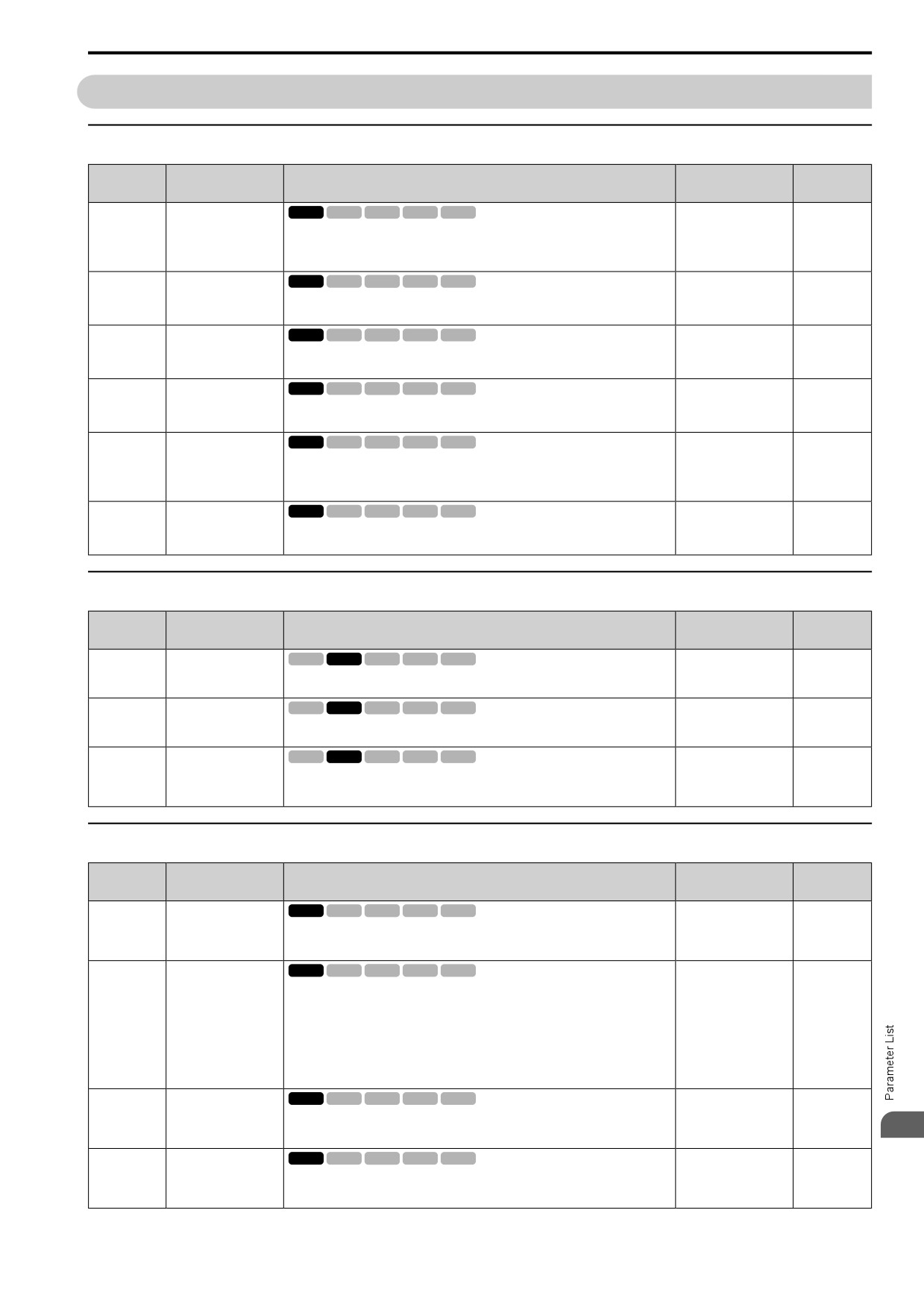
11.11 n: SPECIAL
11.11
n: SPECIAL
◆ n1: HUNTING PREVENTION
No.
Default
Name
Description
Ref.
(Hex.)
(Range)
HuntPrev Selection
V/f
OLV OLV/PM AOLV/PM EZOLV
n1-01
0
676
(0580)
Sets the function to prevent hunting.
(0, 1)
0 : Disabled
1 : Enabled
HuntPrev Gain Setting
V/f
OLV OLV/PM AOLV/PM EZOLV
n1-02
1.00
676
(0581)
Sets the performance of the hunting prevention function. Usually it is not necessary to
(0.00
- 2.50)
change this parameter.
Expert
HuntPrev Time Constant
V/f
OLV OLV/PM AOLV/PM EZOLV
n1-03
Determined by o2-04
676
(0582)
Sets the primary delay time constant of the hunting prevention function. Usually it is
(0 - 500 ms)
not necessary to change this parameter.
Expert
HuntPrev Gain Reverse
V/f
OLV OLV/PM AOLV/PM EZOLV
n1-05
0.00
676
Mode
(0530)
Sets the performance of the hunting prevention function. This parameter adjusts
(0.00
- 2.50)
Reverse run. Usually it is not necessary to change this parameter.
Expert
DCBus Stab.Control
V/f
OLV OLV/PM AOLV/PM EZOLV
n1-13
0
677
(1B59)
Sets the oscillation suppression function for the DC bus voltage.
(0, 1)
Expert
0 : Disabled
1 : Enabled
DCBus Stab Time
V/f
OLV OLV/PM AOLV/PM EZOLV
n1-14
100.0 ms
677
(1B5A)
Adjusts the responsiveness of the oscillation suppression function for the DC bus
(50.0 - 500.0 ms)
voltage. Set n1-13 = 1 [DCBus Stab.Control = Enabled] to enable this parameter.
Expert
◆ n2: AFR - AUTO FREQ REGULATION
No.
Default
Name
Description
Ref.
(Hex.)
(Range)
AFR Gain
V/f
OLV OLV/PM AOLV/PM EZOLV
n2-01
1.00
677
(0584)
Sets the gain of the AFR function as a magnification value. Usually it is not necessary
(0.00
- 10.00)
to change this setting.
AFR Time 1
V/f
OLV OLV/PM AOLV/PM EZOLV
n2-02
50 ms
677
(0585)
Sets the time constant that sets the rate of change for the AFR function. Usually it is not
(0 - 2000 ms)
necessary to change this setting.
AFR Time 2
V/f
OLV OLV/PM AOLV/PM EZOLV
n2-03
750 ms
678
(0586)
Sets the time constant that sets the speed difference of the AFR function. Use this
(0 - 2000 ms)
parameter for speed searches or regeneration. Usually it is not necessary to change this
setting.
◆ n3: HIGHSLIP/OVEREXCITATION BRAKE
No.
Default
Name
Description
Ref.
(Hex.)
(Range)
HSB Dec Freq Width
V/f
OLV OLV/PM AOLV/PM EZOLV
n3-01
5%
679
(0588)
Sets the amount by which the output frequency is to be lowered during high-slip
(1 - 20%)
braking, as a percentage of E1-04 [Max Output Frequency], which represents the 100%
Expert
value.
n3-02
HSB CurrLim Level
V/f
OLV OLV/PM AOLV/PM EZOLV
Determined by C6-01
680
(0589)
Sets the maximum current output during high-slip braking as a percentage, where E2-01
and L8-38
[Mot Rated Current (FLA)] is 100%. Also set the current suppression to prevent
(0 - 150%)
Expert
exceeding drive overload tolerance.
Note:
The upper limit to the setting range changes when the setting for C6-01 [ND/HD
Duty Selection] changes.
•
150% when C6-01 = 0 [HD Rating]
•
120% when C6-01 = 1 [ND Rating]
HSB DwellTime@Stop
V/f
OLV OLV/PM AOLV/PM EZOLV
n3-03
1.0 s
680
(058A)
Sets the dwell time, a length of time when high-slip braking is ending and during which
(0.0 - 10.0 s)
the motor speed decreases and runs at a stable speed. For a set length of time, the drive
11
Expert
will hold the actual output frequency at the minimum output frequency set in E1-09.
HSB Overload Time
V/f
OLV OLV/PM AOLV/PM EZOLV
n3-04
40 s
680
(058B)
Sets the time used to detect oL7 [High Slip Braking Overload], which occurs when the
(30 - 1200 s)
output frequency does not change during high-slip braking. Usually it is not necessary
Expert
to change this parameter.
375
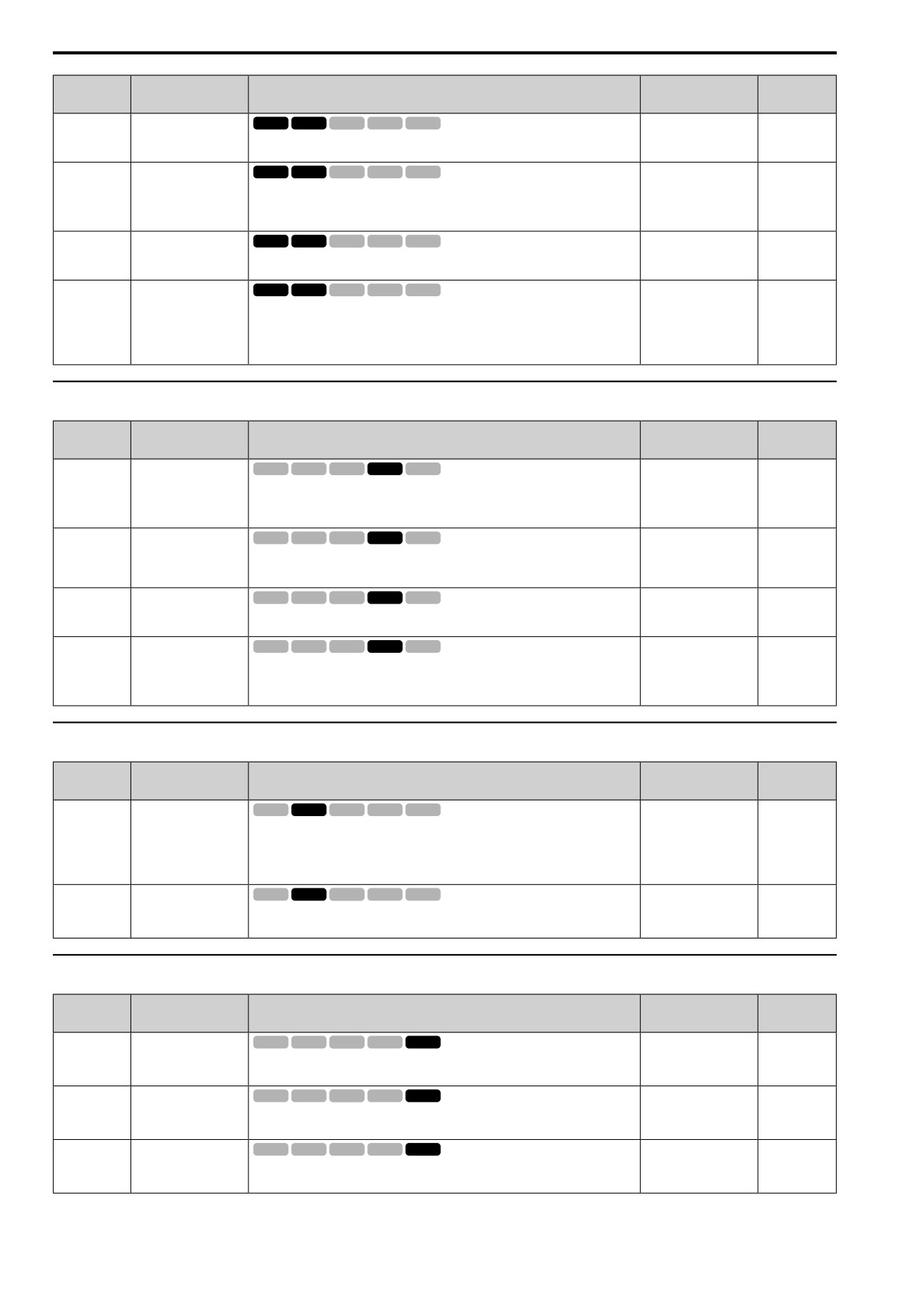
11.11 n: SPECIAL
No.
Default
Name
Description
Ref.
(Hex.)
(Range)
OverExcBr Gain
V/f
OLV OLV/PM AOLV/PM EZOLV
n3-13
1.10
680
(0531)
Sets the gain value that the drive multiplies by the V/f pattern output value during
(1.00
- 1.40)
overexcitation deceleration to calculate the overexcitation level.
OverExcBr Harmonics
V/f
OLV OLV/PM AOLV/PM EZOLV
n3-14
0
681
Selection
(0532)
Sets the function that injects harmonic signals during overexcitation deceleration.
(0, 1)
Expert
0 : Disabled
1 : Enabled
OverExcBr Current
V/f
OLV OLV/PM AOLV/PM EZOLV
n3-21
100%
681
Level
(0579)
Sets the upper limit of the current that is suppressed at the time of overexcitation
(0 - 150%)
deceleration as a percentage of the drive rated current.
OverExcBr Operation
V/f
OLV OLV/PM AOLV/PM EZOLV
n3-23
1
681
(057B)
Sets the direction of motor rotation where the drive will enable overexcitation.
(1 - 3)
1 : Enabled@Both directions
2 : Enabled@FW direction
3 : Enabled@REV direction
◆ n5: FEED FORWARD CONTROL
No.
Default
Name
Description
Ref.
(Hex.)
(Range)
n5: FF Control Selection
V/f
OLV OLV/PM AOLV/PM EZOLV
n5-01
0
682
(05B0)
Sets the feed forward function.
(0, 1)
0 : Disabled
1 : Enabled
Mot Inertia Acceleration
V/f
OLV OLV/PM AOLV/PM EZOLV
n5-02
Determined by C6-01,
682
Time
E5-01, and o2-04
(05B1)
Sets the length of time for the motor to accelerate from the stopped to the maximum
frequency with a single motor at the rated torque. Inertia Tuning automatically sets the
(0.001 - 10.000 s)
motor acceleration time.
FF Control Gain
V/f
OLV OLV/PM AOLV/PM EZOLV
n5-03
1.00
683
(05B2)
Sets the ratio between load inertia and motor inertia. Inertia Tuning automatically sets
(0.00
- 100.00)
the Feedforward Control Gain value.
Speed Response
V/f
OLV OLV/PM AOLV/PM EZOLV
n5-04
Determined by A1-02
683
Frequency
(05B3)
Sets the response frequency for the speed reference. Usually it is not necessary to
(0.00 - 500.00 Hz)
change this parameter.
RUN
Expert
◆ n6: ONLINE TUNING
No.
Default
Name
Description
Ref.
(Hex.)
(Range)
Online Tune Selection
V/f
OLV OLV/PM AOLV/PM EZOLV
n6-01
0
684
(0570)
Sets the type of motor data that Online Tuning uses for OLV control.
(0 - 2)
0 : Disabled
1 : Line-to-Line Resistance Tuning
2 : VoltageAdjustment
Online Tune Gain
V/f
OLV OLV/PM AOLV/PM EZOLV
n6-05
1.0
684
(05C7)
Sets the compensation gain when n6-01 = 2 [Online Tune Selection =
(0.1
- 50.0)
VoltageAdjustment]. Usually it is not necessary to change this parameter.
Expert
◆ n7: SIMPLE VECTOR TUNING
No.
Default
Name
Description
Ref.
(Hex.)
(Range)
LoFreq Damping Gain
V/f
OLV OLV/PM AOLV/PM EZOLV
n7-01
1.0
684
(3111)
Sets the oscillation suppression gain for the low speed range.
(0.1
- 10.0)
Expert
TrqCtrl Response Gain
V/f
OLV OLV/PM AOLV/PM EZOLV
n7-05
50
684
(3115)
Sets the response gain related to changes in the load.
(10 - 1000)
Expert
Speed Calc.Gain1
V/f
OLV OLV/PM AOLV/PM EZOLV
n7-07
15.0 Hz
685
(3117)
Sets the speed calculation gain during usual operation. Usually it is not necessary to
(1.0 - 50.0 Hz)
change this setting.
Expert
376
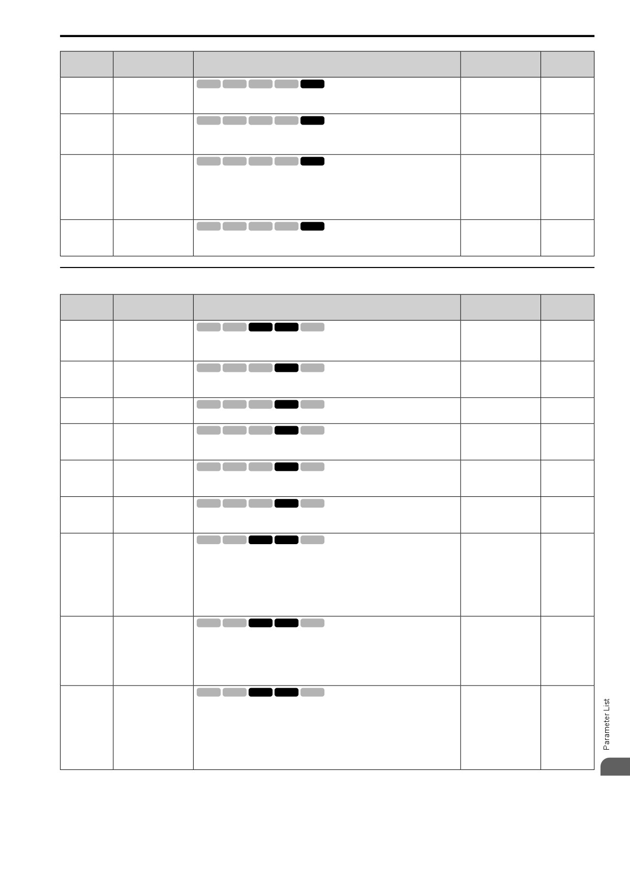
11.11
n: SPECIAL
No.
Default
Name
Description
Ref.
(Hex.)
(Range)
Speed Calc.Gain2
V/f
OLV OLV/PM AOLV/PM EZOLV
n7-08
25.0 Hz
685
(3118)
Sets the speed calculation gain during a speed search.
(1.0 - 50.0 Hz)
Expert
Pull-in SwitchSpeed
V/f
OLV OLV/PM AOLV/PM EZOLV
n7-10
10.0%
685
(311A)
Sets the speed range to operate with the pull-in current command. Drive rated frequency
(0.0
- 100.0%)
= 100% value. If there is a large quantity of oscillation when you operate in the low
Expert
speed range, increase the setting value.
Resist.Temp.
V/f
OLV OLV/PM AOLV/PM EZOLV
n7-17
2
685
Compensation
(3122)
Sets the function to adjust for changes in the motor resistance value caused by changes
(1 to 3)
in the temperature.
1 : Invalid
2 : Valid (1 Time)
3 : Valid (Every Time)
FluxErr CompGain
V/f
OLV OLV/PM AOLV/PM EZOLV
n7-19
5000%
685
(3128)
Sets the gain for magnetic flux compensation. Usually it is not necessary to change this
(0 - 50000%)
setting.
Expert
◆ n8: PM MOTOR CONTROL TUNING
No.
Default
Name
Description
Ref.
(Hex.)
(Range)
PolPos Detection
V/f
OLV OLV/PM AOLV/PM EZOLV
n8-01
50%
686
Current
(0540)
Sets, as a percentage, the Initial Rotor Position Estimated Current, taking the E5-03
(0 - 100%)
[PM Mot Rated Current (FLA)] as the 100% value. Usually it is not necessary to
Expert
change this setting.
Pole Align Current Level
V/f
OLV OLV/PM AOLV/PM EZOLV
n8-02
80%
686
(0541)
Sets the current at the time of polar attraction as a percentage where E5-03 [PM Mot
(0 - 150%)
Rated Current (FLA)] is 100%. Usually it is not necessary to change this setting.
Expert
Observ.Calc Gain2
V/f
OLV OLV/PM AOLV/PM EZOLV
n8-11
Determined by n8-72
686
(054A)
Sets the gain for speed estimation. Usually it is not necessary to change this setting.
(0.0
- 1000.0)
Polar Comp Gain3
V/f
OLV OLV/PM AOLV/PM EZOLV
n8-14
1.000
686
(054D)
Sets the gain for speed estimation. Usually it is not necessary to change this setting.
(0.000
- 10.000)
Expert
Polar Comp Gain4
V/f
OLV OLV/PM AOLV/PM EZOLV
n8-15
0.500
686
(054E)
Sets the gain for speed estimation. Usually it is not necessary to change this setting.
(0.000
- 10.000)
Expert
Mot Back-EMF (Ke)
V/f
OLV OLV/PM AOLV/PM EZOLV
n8-21
0.90
686
Gain
(0554)
Sets the gain for speed estimation. Usually it is not necessary to change this setting.
(0.80
- 1.00)
Expert
InitRotorPos Selection
V/f
OLV OLV/PM AOLV/PM EZOLV
n8-35
Determined by A1-02
687
(0562)
Sets how the drive detects the position of the rotor when the motor starts.
(1 - 3)
Note:
• When you use an SPM motor, set n8-35 = 1.
• When you set n8-35 = 2, do High Frequency Injection Auto-Tuning.
1 : Pull-In
2 : HiFreq Injection
3 : Pulse Injection
HFI Signal Frequency
V/f
OLV OLV/PM AOLV/PM EZOLV
n8-36
500 Hz
687
(0563)
Sets the injection frequency for high frequency injection.
(200 - 1000 Hz)
Note:
• Set n8-35 = 2 [InitRotorPos Selection = HiFreq Injection] or n8-57 = 1 [High-
Freq Injection = Enabled] to enable this parameter.
• The drive automatically calculates this value when High Frequency Injection
Auto-Tuning completes successfully.
HFI Voltage Amplitude
V/f
OLV OLV/PM AOLV/PM EZOLV
n8-37
20.0%
687
Level
(0564)
Sets the high frequency injection amplitude as a percentage where 200 V = 100% for
(0.0
- 50.0%)
200 V class drives and 400 V = 100% for a 400 V class drives. Usually it is not
Expert
necessary to change this setting.
Note:
• Set n8-35 = 2 [InitRotorPos Selection = HiFreq Injection] or n8-57 = 1 [High-
Freq Injection = Enabled] to enable this parameter.
• The drive automatically calculates this value when High Frequency Injection
Auto-Tuning completes successfully.
11
377
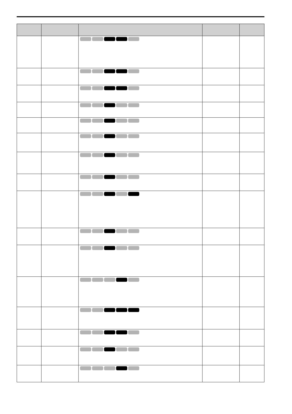
11.11 n: SPECIAL
No.
Default
Name
Description
Ref.
(Hex.)
(Range)
HFI LPF Cutoff Frq
V/f
OLV OLV/PM AOLV/PM EZOLV
n8-39
250 Hz
687
(0566)
Sets the low-pass filter shut-off frequency for high frequency injection.
(0 - 1000 Hz)
Note:
• Set n8-35 = 2 [InitRotorPos Selection = HiFreq Injection] or n8-57 = 1 [High-
Freq Injection = Enabled] to enable this parameter.
• The drive automatically calculates this value when High Frequency Injection
Auto-Tuning completes successfully.
n8-41
HFI PoleDet Pgain
V/f
OLV OLV/PM AOLV/PM EZOLV
2.5
687
(0568)
Sets the response gain for the high frequency injection speed estimation.
(-10.0 - +10.0)
Expert
HFI PoleDet iTime
V/f
OLV OLV/PM AOLV/PM EZOLV
n8-42
0.10 s
688
(0569)
Sets the integral time constant for the high frequency injection speed estimation.
(0.00 - 9.99 s)
Usually it is not necessary to change this setting.
Expert
SpdFbck Det.Gain
V/f
OLV OLV/PM AOLV/PM EZOLV
n8-45
0.80
688
(0538)
Sets the internal speed feedback detection reduction unit gain as a magnification value.
(0.00
- 10.00)
Usually it is not necessary to change this setting.
Pull-In Comp.Time
V/f
OLV OLV/PM AOLV/PM EZOLV
n8-47
5.0 s
688
Constant
(053A)
Sets the time constant the drive uses to align the pull-in current reference value with the
(0.0 - 100.0 s)
actual current value. Usually it is not necessary to change this setting.
Pull-In Current (for PM
V/f
OLV OLV/PM AOLV/PM EZOLV
n8-48
30%
688
Motors)
(053B)
On the basis that parameter E5-03 [PM Mot Rated Current (FLA)] is the 100% value,
(0 - 200%)
this parameter sets the d-axis current that flows to the motor during run at constant
RUN
speed as a percentage.
Heavy Load Id Current
V/f
OLV OLV/PM AOLV/PM EZOLV
n8-49
Determined by E5-01
689
(053C)
Sets the d-axis current to that the drive will supply to the motor to run it at a constant
(-200.0 - +200.0%)
speed with a heavy load. Considers E5-03 [PM Mot Rated Current (FLA)] to be 100%.
RUN
Usually it is not necessary to change this setting.
Expert
Medium Load Iq Level
V/f
OLV OLV/PM AOLV/PM EZOLV
n8-50
80%
689
(High)
(053D)
Sets the load current level at which heavy load control starts where E5-03 [PM Mot
(50 - 255)
Rated Current (FLA)] is 100%. Usually it is not necessary to change this setting.
Expert
Ac/Dec Pull-In Current
V/f
OLV OLV/PM AOLV/PM EZOLV
n8-51
Determined by A1-02
689
(053E)
Sets the pull-in current allowed to flow during acceleration/deceleration as a percentage
(0 - 200%)
of the motor rated current.
Note:
Parameter A1-02 [Control Method Selection] selects which parameter is the motor
rated current.
• A1-02 = 5 [PM OLVector]: E5-03 [PM Mot Rated Current (FLA)]
• A1-02 = 8 [EZ Vector]: E9-06 [Motor Rated Current]
Volt-Err Compensation
V/f
OLV OLV/PM AOLV/PM EZOLV
n8-54
1.00 s
689
Time
(056D)
Sets the time constant that the drive uses when adjusting for voltage errors.
(0.00 - 10.00 s)
Expert
Load Inertia
V/f
OLV OLV/PM AOLV/PM EZOLV
n8-55
1
689
(056E)
Sets the ratio between motor inertia and machine inertia.
(1 - 4)
1 : <1:10
2 : 1:10-1:30
3 : 1:30-1:50
4 : >1:50
High-Freq Injection
V/f
OLV OLV/PM AOLV/PM EZOLV
n8-57
0
690
(0574)
Sets the function that detects motor speed with high frequency injection.
(0, 1)
Note:
When you set n8-57 = 1, doHigh Frequency Injection Auto-Tuning.
0 : Disabled
1 : Enabled
Output Volt Limit Level
V/f
OLV OLV/PM AOLV/PM EZOLV
n8-62
200 V Class: 200.0 V,
690
400 V: 400.0 V
(057D)
Sets the output voltage limit to prevent saturation of the output voltage. Usually it is not
necessary to change this parameter.
(200 V Class: 0.0 to
Expert
230.0 V, 400 V Class:
0.0 to 460.0 V)
Output Voltage Limit P
V/f
OLV OLV/PM AOLV/PM EZOLV
n8-63
1.00
691
Gain
(057E)
Sets the proportional gain for output voltage control. Usually it is not necessary to
(0.00
- 100.00)
change this setting.
Expert
SpdFbk Gain@OV
V/f
OLV OLV/PM AOLV/PM EZOLV
n8-65
1.50
691
Suppression
(065C)
Sets the gain of internal speed feedback detection suppression while the overvoltage
(0.00
- 10.00)
suppression function is operating as a magnification value. Usually it is not necessary to
Expert
change this parameter.
Spd Obs. P Gain Control
V/f
OLV OLV/PM AOLV/PM EZOLV
n8-69
1.00
691
(065D)
Usually it is not necessary to change this setting. Sets the Proportional gain that the
(0.00
- 20.00)
drive uses for speed estimation.
Expert
378
11.11
n: SPECIAL
No.
Default
Name
Description
Ref.
(Hex.)
(Range)
Spd Obs. Method
V/f
OLV OLV/PM AOLV/PM EZOLV
n8-72
2
691
Selection
(0655)
Selects the speed estimation method. Usually it is not necessary to change this setting.
(1, 2)
Expert
1 : Method 1
2 : Method 2
Light Load Iq Level
V/f
OLV OLV/PM AOLV/PM EZOLV
n8-74
30%
691
(05C3)
Set n8-48 [Pull-In Current (for PM Motors)] to the percentage of load current (q-axis
(0 - 255%)
current) that you will apply, where E5-03 [PM Mot Rated Current (FLA)] = a setting
Expert
value of 100%.
Mid Load Iq Level
V/f
OLV OLV/PM AOLV/PM EZOLV
n8-75
50%
691
(Low)
(05C4)
Set n8-78 [Mid Load Id Current] to the percentage of load current (q-axis current) that
(0 - 255%)
you will apply, where E5-03 [PM Mot Rated Current (FLA)] = a setting value of 100%.
Expert
Hvy Load Iq Level
V/f
OLV OLV/PM AOLV/PM EZOLV
n8-77
90%
692
(05CE)
Set n8-49 [Heavy Load Id Current] to the percentage of load current (q-axis current)
(0 - 255%)
that you will apply, where E5-03 [PM Mot Rated Current (FLA)] = a setting value of
Expert
100%.
Mid Load Id Current
V/f
OLV OLV/PM AOLV/PM EZOLV
n8-78
0%
692
(05F4)
Sets the level of the pull-in current as a percentage, where E5-03 [PM Mot Rated
(0 - 255%)
Current (FLA)] = 100%.
RUN
Expert
Pull-In
V/f
OLV OLV/PM AOLV/PM EZOLV
n8-79
50%
692
Curr@Deceleration
(05FE)
Sets the pull-in current that can flow during deceleration as a percentage of the E5-03
(0 - 200%)
[PM Mot Rated Current (FLA)].
Note:
When n8-79 = 0, the drive will use the value set in n8-51 [Ac/Dec Pull-In Current].
Polarity Det Current
V/f
OLV OLV/PM AOLV/PM EZOLV
n8-84
100%
692
(02D3)
Sets the current that the drive uses to estimate the initial motor magnetic pole as a
(0 - 150%)
percentage where E5-03 [PM Mot Rated Current (FLA)] = 100%.
Expert
O/P VoltLim Method
V/f
OLV OLV/PM AOLV/PM EZOLV
n8-87
0
692
(02BC)
Sets the method of output voltage limit. If there is vibration in the constant output
(0, 1)
range, set Feedforward Method. Usually it is not necessary to change this setting.
0 : Feedback Method
1 : Feedforward Method
VoutLimSw Level
V/f
OLV OLV/PM AOLV/PM EZOLV
n8-88
400%
693
(02BD)
Sets the current level at which output voltage limit sequence selection occurs as a
(0 - 400%)
percentage where the motor rated current is 100%. Normally there is no need to change
this setting.
Note:
Parameter A1-02 [Control Method] selects which parameter is the motor rated
current.
• A1-02 = 5, 6 [PM OLVector, PM AOLVector]: E5-03 [PM Mot Rated Current
(FLA)]
• A1-02 = 8 [EZ Vector]: E9-06 [Motor Rated Current]
VoutLimSwHysteresis
V/f
OLV OLV/PM AOLV/PM EZOLV
n8-89
3%
693
(02BE)
Sets the hysteresis width of the current level at which output voltage limit sequence
(0 - 400%)
selection occurs as a percentage where the motor rated current is 100%. Normally there
is no need to change this setting.
Note:
Parameter A1-02 [Control Method] selects which parameter is the motor rated
current.
• A1-02 = 5, 6 [PM OLVector, PM AOLVector]: E5-03 [PM Mot Rated Current
(FLA)]
• A1-02 = 8 [EZ Vector]: E9-06 [Motor Rated Current]
VoutLimSwSpeed
V/f
OLV OLV/PM AOLV/PM EZOLV
n8-90
200%
693
(02BF)
Sets the speed level at which output voltage limit sequence selection occurs as a
(0 - 200%)
percentage where the maximum output frequency is 100%. Usually it is not necessary to
change this setting.
Note:
Parameter A1-02 [Control Method] selects which parameter is the maximum output
frequency.
• A1-02 = 5, 6 [PM OLVector, PM AOLVector]: E1-04 [Max Output Frequency]
• A1-02 = 8 [EZ Vector]: E9-02 [Maximum Speed]
VoutLim Id Limit
V/f
OLV OLV/PM AOLV/PM EZOLV
n8-91
-50%
693
(02F7)
Sets the limit value of feedback output voltage limit Id operation. Enabled when n8-87
(-200 - 0%)
= 0 [O/P VoltLim Method = Speed Feedback Form]. Usually it is not necessary to
change this setting.
11
379
11.11 n: SPECIAL
No.
Default
Name
Description
Ref.
(Hex.)
(Range)
FluxPos Est.Method
V/f
OLV OLV/PM AOLV/PM EZOLV
n8-94
2
693
(012D)
Sets the criteria that the drive uses to find changes in speed or load. Usually it is not
(1, 2)
necessary to change this setting.
Expert
1 : Softstarter
2 : Speed Feedback
FluxPos Est.Filter Time
V/f
OLV OLV/PM AOLV/PM EZOLV
n8-95
30 ms
693
(012E)
Sets the time constant of the filter used for the recognition criteria value for speed and
(0 - 100 ms)
load changes. Usually it is not necessary to change this setting.
Expert
◆ nA: PM MOTOR CONTROL TUNING
No.
Default
Name
Description
Ref.
(Hex.)
(Range)
V/f
OLV OLV/PM AOLV/PM EZOLV
nA-01
Obs Calc Gain 3
30.0
694
(3129)
Sets the gain for speed estimation. Usually it is not necessary to change this setting.
(0.0
- 1000.0)
Expert
380
11.12
o: KEYPAD
11.12
o: KEYPAD
◆ o1: KEYPAD DISPLAY
No.
Default
Name
Description
Ref.
(Hex.)
(Range)
User Monitor Selection
V/f
OLV OLV/PM AOLV/PM EZOLV
o1-01
106
696
(0500)
Sets the U: MONITORS for the Drive Mode. This parameter is only available when you
(104 - 855)
use an LED keypad.
RUN
Mon.Sel@Power-Up
V/f
OLV OLV/PM AOLV/PM EZOLV
o1-02
1
696
(0501)
Sets the monitor item that the keypad screen shows after energizing the drive. Refer to
(1 - 5)
“U: MONITORS” for information about the monitor items that the keypad screen can
RUN
show. This parameter is only available when you use an LED keypad.
1 : FreqReference (U1-01)
2 : Direction
3 : OutFrequency (U1-02)
4 : OutCurrent (U1-03)
5 : User Monitor (o1-01)
FrqDisplay Unit
V/f
OLV OLV/PM AOLV/PM EZOLV
o1-03
Determined by A1-02
696
Selection
(0502)
Sets the display units for the frequency reference and output frequency.
(0 - 3)
0 : 0.01 Hz
1 : 0.01% (100%=E1-04)
2 : rpm
3 : User-selected units
V/f Pattern Unit for
V/f
OLV OLV/PM AOLV/PM EZOLV
o1-04
Determined by A1-02
697
Display
(0503)
Sets the setting unit for parameters that set the V/f pattern frequency.
(0, 1)
0 : Hz
1 : rpm
LCD Contrast
V/f
OLV OLV/PM AOLV/PM EZOLV
o1-05
5
698
Adjustment
(0504)
Sets the contrast of the LCD display on the keypad.
(0 - 10)
RUN
FrqDisplay Max Value
V/f
OLV OLV/PM AOLV/PM EZOLV
o1-10
Determined by o1-03
698
(0520)
Sets the value that the drive shows as the maximum output frequency.
(1 - 60000)
FrqDisplay Decimal
V/f
OLV OLV/PM AOLV/PM EZOLV
o1-11
Determined by o1-03
698
Places
(0521)
Sets the number of decimal places for frequency reference and monitor values.
(0 - 3)
0 : (XXXXX) No Decimal Places
1 : (XXXX.X) 1 Decimal Place
2 : (XXX.XX) 2 Decimal Places
3 : (XX.XXX) 3 Decimal Places
Cust.Monitor 1 to 12
V/f
OLV OLV/PM AOLV/PM EZOLV
o1-24 to o1-35:
o1-24: 101
698
(11AD - 11B8)
Sets a maximum of 12 monitors as user monitors. This parameter is only available when
o1-25: 102
using an LCD keypad.
RUN
o1-26: 103
o1-27 to o1-35: 0
(0, 101 - 999)
LCD Backlight
V/f
OLV OLV/PM AOLV/PM EZOLV
o1-36
3
699
Brightness
(11B9)
Sets the intensity of the LCD keypad backlight.
(1 - 5)
RUN
LCD Blight ON/OFF
V/f
OLV OLV/PM AOLV/PM EZOLV
o1-37
1
699
Selection
(11BA)
Sets the automatic shut off function for the LCD backlight.
(0, 1)
RUN
0 : OFF
1 : ON
LCD Blight Off-Delay
V/f
OLV OLV/PM AOLV/PM EZOLV
o1-38
60 s
699
(11BB)
Sets the time until the LCD backlight automatically turns off.
(10 - 300 s)
RUN
Show Init Screen
V/f
OLV OLV/PM AOLV/PM EZOLV
o1-39
1
699
(11BC)
Sets the function to show the LCD keypad initial setup screen each time the drive is
(0, 1)
energized. This parameter is only available when using an LCD keypad.
RUN
0 : No
1 : Yes
Home Screen Selection
V/f
OLV OLV/PM AOLV/PM EZOLV
o1-40
0
700
Mode
(11BD)
Sets the monitor display mode for the Home screen. This parameter is only available
(0, 10 - 12)
11
when using an LCD keypad.
RUN
0 : Monitors
10 : Bar Graph
11 : Analog Gauge
12 : Trend Plot
381
11.12 o: KEYPAD
No.
Default
Name
Description
Ref.
(Hex.)
(Range)
1stMon Area Selection
V/f
OLV OLV/PM AOLV/PM EZOLV
o1-41
0
700
(11C1)
Sets the horizontal range used to display the monitor set in o1-24 [Cust.Monitor 1] as a
(0, 1)
bar graph. This parameter is only available when using an LCD keypad.
RUN
0 : +/- Area (- o1-42 - o1-42 )
1 : + Area (0 - o1-42 )
1stMon Area Setting
V/f
OLV OLV/PM AOLV/PM EZOLV
o1-42
100.0%
700
(11C2)
Sets the horizontal axis value used to display the monitor set in o1-24 [Cust.Monitor 1]
(0.0
- 100.0%)
as a bar graph. This parameter is only available when using an LCD keypad.
RUN
2ndMon Area Selection
V/f
OLV OLV/PM AOLV/PM EZOLV
o1-43
0
700
(11C3)
Selects the horizontal range used to display the monitor set in o1-25 [Cust.Monitor 2]
(0, 1)
as a bar graph. This parameter is only available when using an LCD keypad.
RUN
0 : + - Area (- o1-44 - o1-44)
1 : + Area (0 - o1-44)
2ndMon Area Setting
V/f
OLV OLV/PM AOLV/PM EZOLV
o1-44
100.0%
700
(11C4)
Sets the horizontal axis value used to display the monitor set in o1-25 [Cust.Monitor 2]
(0.0
- 100.0%)
as a bar graph. This parameter is only available when using an LCD keypad.
RUN
3rdMon Area Selection
V/f
OLV OLV/PM AOLV/PM EZOLV
o1-45
0
700
(11C5)
Sets the horizontal range used to display the monitor set in o1-26 [Cust.Monitor 3] as a
(0, 1)
bar graph. This parameter is only available when using an LCD keypad.
RUN
0 : + - Area (- o1-46 - o1-46)
1 : + Area (0 - o1-46 )
3rdMon Area Setting
V/f
OLV OLV/PM AOLV/PM EZOLV
o1-46
100.0%
701
(11C6)
Sets the horizontal axis value used to display the monitor set in o1-26 [Cust.Monitor 3]
(0.0
- 100.0%)
as a bar graph. This parameter is only available when using an LCD keypad.
RUN
Trend Plot 1 Min Scale
V/f
OLV OLV/PM AOLV/PM EZOLV
o1-47
-100.0%
701
Value
(11C7)
Sets the horizontal axis minimum value used to display the monitor set in o1-24 [Cust.
(-300.0 - +300.0%)
Monitor 1] as a trend plot. This parameter is only available when using an LCD keypad.
RUN
Trend Plot 1 Max Scale
V/f
OLV OLV/PM AOLV/PM EZOLV
o1-48
100.0%
701
Value
(11C8)
Sets the horizontal axis maximum value used to display the monitor set in o1-24 [Cust.
(-300.0 - +300.0%)
Monitor 1] as a trend plot. This parameter is only available when using an LCD keypad.
RUN
Trend Plot 2 Min Scale
V/f
OLV OLV/PM AOLV/PM EZOLV
o1-49
-100.0%
701
Value
(11C9)
Sets the horizontal axis minimum value used to display the monitor set in o1-25 [Cust.
(-300.0 - +300.0%)
Monitor 2] as a trend plot. This parameter is only available when using an LCD keypad.
RUN
Trend Plot 2 Max Scale
V/f
OLV OLV/PM AOLV/PM EZOLV
o1-50
100.0%
701
Value
(11CA)
Sets the horizontal axis maximum value used to display the monitor set in o1-25 [Cust.
(-300.0 - +300.0%)
Monitor 2] as a trend plot. This parameter is only available when using an LCD keypad.
RUN
Trend Plot Time Scale
V/f
OLV OLV/PM AOLV/PM EZOLV
o1-51
300 s
701
Setting
(11CB)
Sets the time scale (horizontal axis) to display the trend plot. When you change this
(1 - 3600 s)
setting, the drive automatically adjusts the data sampling time. This parameter is only
RUN
available when using an LCD keypad.
AnGauge Area Selection
V/f
OLV OLV/PM AOLV/PM EZOLV
o1-55
1
701
(11EE)
Sets the range used to display the monitor set in o1-24 [Custom Monitor 1] as an analog
(0, 1)
gauge. This parameter is only available when using an LCD keypad.
RUN
0 : + - Area (- o1-56 - o1-56 )
1 : + Area (0 - o1-56 )
AnGauge Area Setting
V/f
OLV OLV/PM AOLV/PM EZOLV
o1-56
100.0%
701
(11EF)
Sets the value used to display the monitor set in o1-24 [Cust.Monitor 1] as an analog
(0.0
- 100.0%)
meter. This parameter is only available when using an LCD keypad.
RUN
Mot Capacity Unit
V/f
OLV OLV/PM AOLV/PM EZOLV
o1-58
0
702
(3125)
Sets the setting unit for parameters that set the motor rated power.
(0, 1)
0 : kW
1 : HP
382
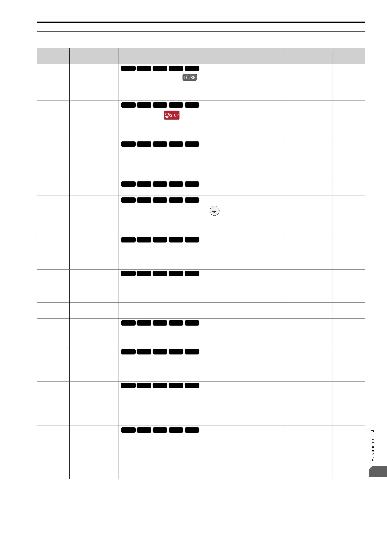
11.12 o: KEYPAD
◆ o2: KEYPAD OPERATION
No.
Default
Name
Description
Ref.
(Hex.)
(Range)
LO/RE Key Selection of
V/f
OLV OLV/PM AOLV/PM EZOLV
o2-01
1
702
Function
(0505)
(0, 1)
Sets the function that lets you use
to switch between LOCAL and REMOTE
Modes.
0 : Disabled
1 : Enabled
STOP Key Selection of
V/f
OLV OLV/PM AOLV/PM EZOLV
o2-02
1
703
Function
(0506)
(0, 1)
Sets the function to use
on the keypad to stop the drive when the Run
command source for the drive is REMOTE (external) and not assigned to the keypad.
0 : Disabled
1 : Enabled
UserPar Set Default
V/f
OLV OLV/PM AOLV/PM EZOLV
o2-03
0
703
Values
(0507)
Sets the function to keep the settings of changed parameters as user parameter defaults
(0 - 2)
to use during initialization.
0 : No change
1 : Set defaults
2 : Clear all
Drive KVA Selection
V/f
OLV OLV/PM AOLV/PM EZOLV
o2-04
Determined by the drive
703
(0508)
Sets the Drive Model code. Set this parameter after replacing the control board.
(-)
LCD FreqRef
V/f
OLV OLV/PM AOLV/PM EZOLV
o2-05
0
704
Mode@Home Screen
(0509)
(0, 1)
Sets the function that makes it necessary to push
to use the keypad to change the
frequency reference value while in Drive Mode.
0 : Disabled
1 : Enabled
Keypad Disconnect
V/f
OLV OLV/PM AOLV/PM EZOLV
o2-06
0
704
Detection
(050A)
Sets the function that stops the drive if you disconnect the keypad connection cable
(0, 1)
from the drive or if you damage the cable while the keypad is the Run command source.
0 : Disabled
1 : Enabled
Keypad Dir@Power-Up
V/f
OLV OLV/PM AOLV/PM EZOLV
o2-07
0
704
(0527)
Sets the direction of motor rotation when the drive is energized and the keypad is the
(0, 1)
Run command source.
0 : Forward
1 : Reverse
Region Code for
o2-09
-
-
705
Initialization
(050D)
Parameter Write during
V/f
OLV OLV/PM AOLV/PM EZOLV
o2-19
0
705
Uv
(061F)
Lets you change parameters during Uv [Undervoltage].
( 0, 1 )
Expert
0 : Disable
1 : Enable
Ext24V Off Warning
V/f
OLV OLV/PM AOLV/PM EZOLV
o2-23
0
705
Display
(11F8)
Sets the function to give a warning if the backup external 24 V power supply turns off
(0, 1)
when the main circuit power supply is in operation.
RUN
0 : Disabled
1 : Enabled
Ext24V Mode Warning
V/f
OLV OLV/PM AOLV/PM EZOLV
o2-26
0
705
Display
(1563)
When you connect a backup external 24 V power supply, this parameter sets the
(0, 1)
function to trigger an alarm when the main circuit power supply voltage decreases.
Note:
The drive will not run when it is operating from one 24-V external power supply.
0 : Disabled
1 : Enabled
BLE Disconn.
V/f
OLV OLV/PM AOLV/PM EZOLV
o2-27
3
705
Selection@BLE Ctrl
(1565)
Sets drive operation if the Bluetooth device is disconnected when you operate the drive
(0 - 4)
in Bluetooth Mode.
0 : Ramp->Stop
1 : Coast->Stop
2 : Fast Stop (C1-09)
3 : Alarm Only
4 : No Alarm Display
11
383
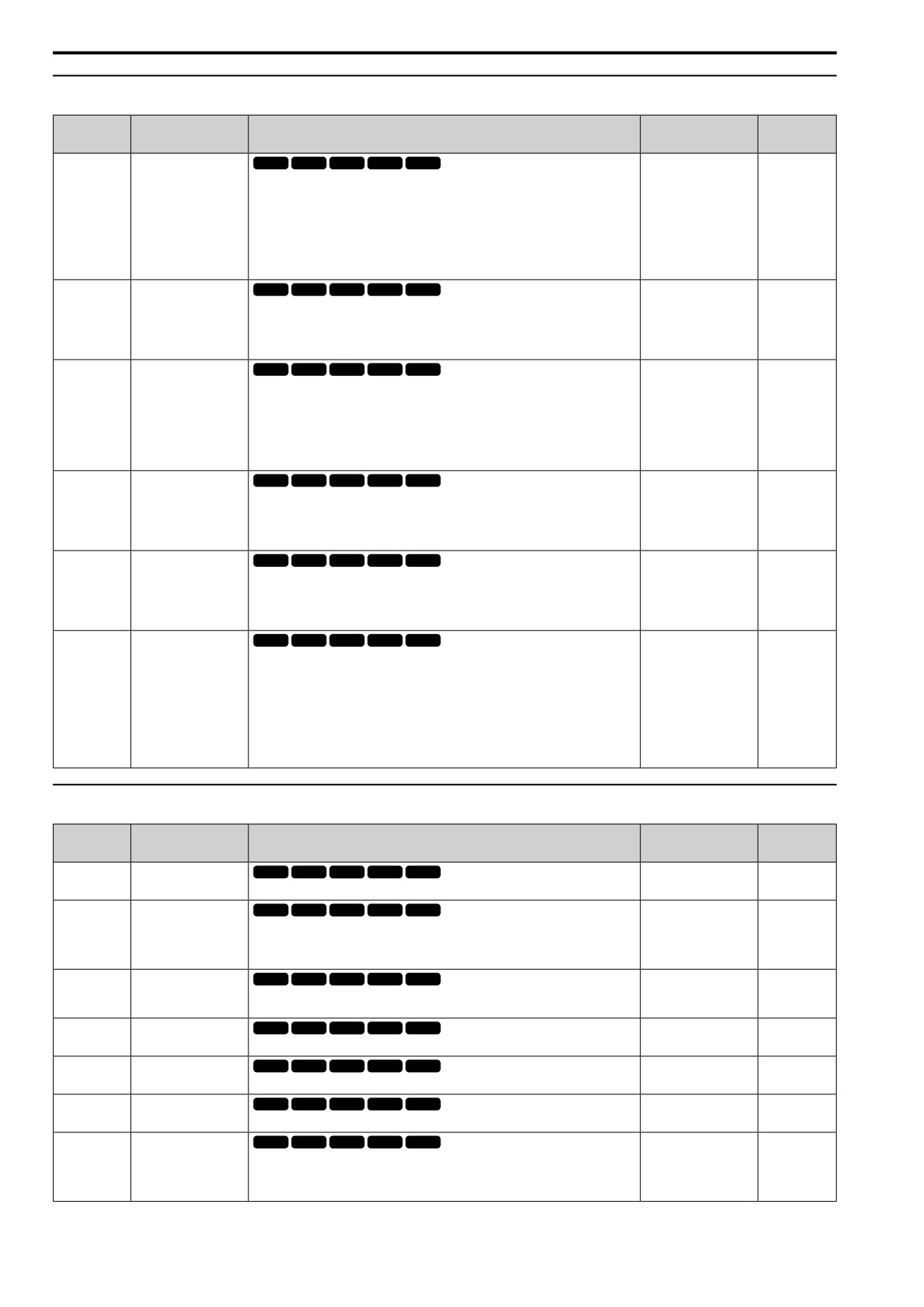
11.12 o: KEYPAD
◆ o3: COPY FUNCTION
No.
Default
Name
Description
Ref.
(Hex.)
(Range)
COPY Keypad Selection
V/f
OLV OLV/PM AOLV/PM EZOLV
o3-01
0
706
of Mode
(0515)
Sets the function that saves and copies drive parameters to a different drive with the
(0 - 4)
keypad.
0 : Copy Select
1 : Bck (Drive->OPE)
2 : Res (OPE->Drive)
3 : Verify (Check)
4 : Del (Clear OPE Memory)
COPY Allow Selection
V/f
OLV OLV/PM AOLV/PM EZOLV
o3-02
0
706
(0516)
Sets the copy function when o3-01 = 1 [COPY Keypad Selection of Mode = Bck
(0, 1)
(Drive->OPE)].
0 : Disabled
1 : Enabled
COPY Memory
V/f
OLV OLV/PM AOLV/PM EZOLV
o3-04
0
706
Selection
(0B3E)
Sets the storage location for drive parameters when you back up and restore parameters.
(0 - 3)
This parameter is only available when using an LCD keypad.
0 : Memory 1
1 : Memory 2
2 : Memory 3
3 : Memory 4
COPY Items Selection
V/f
OLV OLV/PM AOLV/PM EZOLV
o3-05
0
706
(0BDA)
Sets which parameters are backed up, restored, and referenced. This parameter is only
(0, 1)
available when using an LCD keypad.
0 : Std
1 : Std+Solution
AutoBackup Selection
V/f
OLV OLV/PM AOLV/PM EZOLV
o3-06
1
707
(0BDE)
Sets the function that automatically backs up parameters. This parameter is only
(0, 1)
available when using an LCD keypad.
0 : Disabled
1 : Enabled
AutoBackup Lapse
V/f
OLV OLV/PM AOLV/PM EZOLV
o3-07
2
707
(0BDF)
Sets the interval at which the automatic parameter backup function saves parameters
(1 - 4)
from the drive to the keypad.
Note:
This parameter is only available when using an LCD keypad.
1 : 10 minutes
2 : 30 minutes
3 : 60 minutes
4 : 12 hours
◆ o4: MAINTENANCE MONITORS
No.
Default
Name
Description
Ref.
(Hex.)
(Range)
Cum.Oper TimeSetting
V/f
OLV OLV/PM AOLV/PM EZOLV
o4-01
0h
707
(050B)
Sets the initial value of the cumulative drive operation time in 10-hour units.
(0 - 9999 h)
Cum.Oper TimeSelect
V/f
OLV OLV/PM AOLV/PM EZOLV
o4-02
1
708
(050C)
Sets the condition that counts the cumulative operation time.
(1, 2)
1 : Log Power-On Time
2 : Log Run Time
Fan.Oper Setting
V/f
OLV OLV/PM AOLV/PM EZOLV
o4-03
0h
708
(050E)
Sets the value from which to start the cumulative drive cooling fan operation time in 10-
(0 - 9999 h)
hour units.
Cap.Maint.Setting
V/f
OLV OLV/PM AOLV/PM EZOLV
o4-05
0%
708
(051D)
Sets the U4-05 [Capacitor Maintenance] monitor value.
(0 - 150%)
PreChgRly Preset
V/f
OLV OLV/PM AOLV/PM EZOLV
o4-07
0%
708
Maintenance Cnt
(0523)
Sets the U4-06 [SoftChgRelay Maint] monitor value.
(0 - 150%)
IGBT Preset
V/f
OLV OLV/PM AOLV/PM EZOLV
o4-09
0%
708
Maintenance Cnt
(0525)
Sets the U4-07 [IGBT Maintenance] monitor value.
(0 - 150%)
Flt.History Initialization
V/f
OLV OLV/PM AOLV/PM EZOLV
o4-11
0
709
(0510)
Resets the records of Monitors U2: FAULT and U3: FAULT HISTORY.
(0, 1)
0 : No Reset
1 : Reset
384
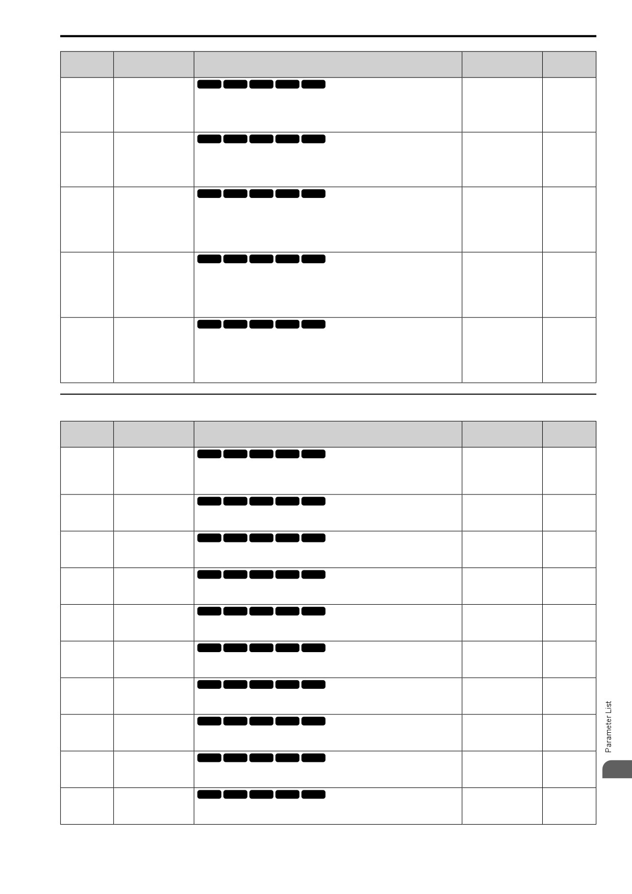
11.12
o: KEYPAD
No.
Default
Name
Description
Ref.
(Hex.)
(Range)
kWh Monitor
V/f
OLV OLV/PM AOLV/PM EZOLV
o4-12
0
709
Initialization
(0512)
Resets the monitor values for U4-10 [kWh Lower 4Digits] and U4-11 [kWh Upper
(0, 1)
5Digits].
0 : No Reset
1 : Reset
NumOfRunCom Init
V/f
OLV OLV/PM AOLV/PM EZOLV
o4-13
0
709
Counter
(0528)
Resets the monitor values for U4-02 [Num of Run Commands], U4-24 [No of Travels
(0, 1)
(L)], and U4-25 [No of Travels(H)].
0 : No Reset
1 : Reset
Time Format
V/f
OLV OLV/PM AOLV/PM EZOLV
o4-22
0
709
(154F)
Sets the time display format. This parameter is only available when using an LCD
(0 - 2)
keypad.
RUN
0 : 24 Hour Clock
1 : 12 Hour Clock
2 : 12 Hour JP Clock
Date Format
V/f
OLV OLV/PM AOLV/PM EZOLV
o4-23
0
709
(1550)
Sets the date display format. This parameter is only available when using an LCD
(0 - 2)
keypad.
RUN
0 : YYYY/MM/DD
1 : DD/MM/YYYY
2 : MM/DD/YYYY
bAT Detection Selection
V/f
OLV OLV/PM AOLV/PM EZOLV
o4-24
0
710
(310F)
Sets the operation when the drive detects bAT [Keypad Battery Low Voltage] and TiM
(0 - 2)
[Keypad Time Not Set]. This parameter is only available when you use an LCD keypad.
RUN
0 : Disabled
1 : Enable (Alarm Detected)
2 : Enable (Fault Detected)
◆ o5: DATA LOGGER
No.
Default
Name
Description
Ref.
(Hex.)
(Range)
Log Start Selection
V/f
OLV OLV/PM AOLV/PM EZOLV
o5-01
0
712
(1551)
Sets the data log function. This parameter is only available when using an LCD keypad.
(0 - 1)
RUN
0 : OFF
1 : ON (Data Logging)
Log Sample Lapse
V/f
OLV OLV/PM AOLV/PM EZOLV
o5-02
1000 ms
713
(1552)
Sets the data log sampling cycle. This parameter is only available when using an LCD
(100 - 60000 ms)
keypad.
RUN
Log Mon Data 1
V/f
OLV OLV/PM AOLV/PM EZOLV
o5-03
101
713
(1553)
Sets the data log monitor. This parameter is only available when using an LCD keypad.
(000, 101 - 999)
RUN
Log Mon Data 2
V/f
OLV OLV/PM AOLV/PM EZOLV
o5-04
102
713
(1554)
Sets the data log monitor. This parameter is only available when using an LCD keypad.
(000, 101 - 999)
RUN
Log Mon Data 3
V/f
OLV OLV/PM AOLV/PM EZOLV
o5-05
103
713
(1555)
Sets the data log monitor. This parameter is only available when using an LCD keypad.
(000, 101 - 999)
RUN
Log Mon Data 4
V/f
OLV OLV/PM AOLV/PM EZOLV
o5-06
107
713
(1556)
Sets the data log monitor. This parameter is only available when using an LCD keypad.
(000, 101 - 999)
RUN
Log Mon Data 5
V/f
OLV OLV/PM AOLV/PM EZOLV
o5-07
108
714
(1557)
Sets the data log monitor. This parameter is only available when using an LCD keypad.
(000, 101 - 999)
RUN
Log Mon Data 6
V/f
OLV OLV/PM AOLV/PM EZOLV
o5-08
000
714
(1558)
Sets the data log monitor. This parameter is only available when using an LCD keypad.
(000, 101 - 999)
RUN
Log Mon Data 7
V/f
OLV OLV/PM AOLV/PM EZOLV
o5-09
000
714
(1559)
Sets the data log monitor. This parameter is only available when using an LCD keypad.
(000, 101 - 999)
11
RUN
Log Mon Data 8
V/f
OLV OLV/PM AOLV/PM EZOLV
o5-10
000
714
(155A)
Sets the data log monitor. This parameter is only available when using an LCD keypad.
(000, 101 - 999)
RUN
385
11.12 o: KEYPAD
No.
Default
Name
Description
Ref.
(Hex.)
(Range)
Log Mon Data 9
V/f
OLV OLV/PM AOLV/PM EZOLV
o5-11
000
714
(155B)
Sets the data log monitor. This parameter is only available when using an LCD keypad.
(000, 101 - 999)
RUN
Log Mon Data 10
V/f
OLV OLV/PM AOLV/PM EZOLV
o5-12
000
715
(155C)
Sets the data log monitor. This parameter is only available when using an LCD keypad.
(000, 101 - 999)
RUN
386
11.13 q: Q2PACK PARAMETERS
11.13
q: Q2PACK PARAMETERS
◆ q1-01 to q8-40: Q2pack Parameters
No.
Default
Name
Description
(Hex.)
(Range)
Reserved for Q2pack
V/f
OLV OLV/PM AOLV/PM EZOLV
q1-01 to q8-40
These parameters are
reserved for use with
(1600 - 17E7)
Refer to “Q2pack Operation Manual”.
Q2pack.
11
387
11.14 r: Q2PACK JOINTS
11.14
r: Q2PACK JOINTS
◆ r1: Q2PACK JOINTS
No.
Default
Name
Description
(Hex.)
(Range)
Connection 1a to
V/f
OLV OLV/PM AOLV/PM EZOLV
r1-01 to r1-40:
0
Connection 20b
(1840 - 1867)
Q2pack Joints Parameters 1 to 20 (Upper / Lower)
(0 - FFFFH)
388
11.15 T: AUTOTUNING
11.15
T: AUTOTUNING
◆ T0: TUNE MODE
No.
Default
Name
Description
Ref.
(Hex.)
(Range)
T0-00
Tune Mode Selection
V/f
OLV OLV/PM AOLV/PM EZOLV
0
716
(1197)
Sets the type of Auto-Tuning.
(0, 1)
0 : Motor Parameter Tuning
1 : Control Tuning
◆ T1: INDUCTION MOTOR
No.
Default
Name
Description
Ref.
(Hex.)
(Range)
V/f
OLV OLV/PM AOLV/PM EZOLV
T1-00
Mot1/Mot2 Selection
1
716
(0700)
Sets which motor to tune when motor 1/2 switching is enabled.
(1, 2)
You can only use the keypad to set this parameter. You cannot use external input
terminals to set it.
Note:
Set H1-xx = 61 [Motor 2 Select] to enable this parameter. When H1-xx ≠ 61 the
keypad will not show this parameter.
1 : Motor 1 (sets E1-xx, E2-xx)
2 : Motor 2 (sets E3-xx, E4-xx)
T1-01
Auto-tuning Mode
V/f
OLV OLV/PM AOLV/PM EZOLV
Determined by A1-02
716
Selection
(0701)
Sets the type of Auto-Tuning.
(Determined by A1-02)
0 : Rotary Auto Tune
1 : Static1 AutoTune
2 : Static (R)
T1-02
Motor Rated Power
V/f
OLV OLV/PM AOLV/PM EZOLV
Determined by o2-04,
717
C6-01
(0702)
Uses the units set in o1-58 [Mot Capacity Unit] to set the motor rated output power.
(0.00 - 650.00 kW)
T1-03
Motor Rated Voltage
V/f
OLV OLV/PM AOLV/PM EZOLV
Determined by o2-04,
717
C6-01
(0703)
Sets the rated voltage (V) of the motor. Enter the base speed voltage for constant output
motors.
(200 V Class: 0.0 - 255.5
V, 400 V Class: 0.0 -
511.0 V)
T1-04
Motor Rated Current
V/f
OLV OLV/PM AOLV/PM EZOLV
Determined by o2-04
717
(0704)
Sets the rated current (A) of the motor.
(10% to 200% of the
drive rated current)
T1-05
Motor Base Frequency
V/f
OLV OLV/PM AOLV/PM EZOLV
50.0 Hz
717
(0705)
Sets the base frequency (Hz) of the motor.
(0.0 - 590.0 Hz)
T1-06
Motor Poles Number
V/f
OLV OLV/PM AOLV/PM EZOLV
4
717
(0706)
Sets the number of motor poles.
(2 to 120)
T1-07
Motor Base Speed
V/f
OLV OLV/PM AOLV/PM EZOLV
1450 min-1 (r/min)
717
(0707)
Sets the motor base speed for Auto-Tuning (min-1 (r/min)).
(0 - 35400 min-1 (r/min))
V/f
OLV OLV/PM AOLV/PM EZOLV
T1-09
Motor NoLoad Current
-
718
(0709)
Sets the no-load current of the motor.
(0A - T1-04; max. of
2999.9)
T1-10
Motor Rated Slip
V/f
OLV OLV/PM AOLV/PM EZOLV
-
718
Frequency
(070A)
Sets motor rated slip.
(0.000 - 20.000 Hz)
V/f
OLV OLV/PM AOLV/PM EZOLV
T1-11
Motor Iron Loss
Determined by E2-11 or
718
E4-11
(070B)
Sets the iron loss for calculating the energy-saving coefficient.
(0 - 65535 W)
11
389
11.15 T: AUTOTUNING
No.
Default
Name
Description
Ref.
(Hex.)
(Range)
T1-12
Test Mode Selection
V/f
OLV OLV/PM AOLV/PM EZOLV
0
718
(0BDB)
Sets the function to enable Test Mode after Stationary Auto-Tuning. When you can
(0, 1)
operate the motor with a light load attached after Stationary Auto-Tuning is complete,
enable this parameter.
Note:
You must first set T1-10 = 0 [Motor Rated Slip Frequency = 0 Hz] to enable this
parameter.
0 : No
1 : Yes
T1-13
No-load Voltage
V/f
OLV OLV/PM AOLV/PM EZOLV
T1-03 × 0.9
718
(0BDC)
Sets the no-load voltage of the motor. When the no-load voltage at rated speed is
(200 V Class: 0.0 - 255.0
available, for example on the motor test report, set the voltage in this parameter. If the
V, 400 V Class: 0.0 -
no-load voltage is not available, do not change this parameter.
510.0 V)
Note:
To get the same qualities as a Yaskawa 1000-series drive or previous series drive,
set this parameter = T1-03 [Motor Rated Voltage].
◆ T2: PM MOTOR
No.
Default
Name
Description
Ref.
(Hex.)
(Range)
V/f
OLV OLV/PM AOLV/PM EZOLV
T2-01
PM AutoTune Mode
0
719
Select
(0750)
Sets the type of Auto-Tuning for PM motors.
(Determined by A1-02)
0 : PM Motor Parameter Settings
1 : PM Static Full AutoTune
2 : PM Static R Autotune
4 : PM Rotary Autotune
5 : High Frequency Injection
T2-02
PMMot Code Selection
V/f
OLV OLV/PM AOLV/PM EZOLV
Determined by A1-02
719
and o2-04
(0751)
If the drive is operating an SMRD, SMRA, or SSR1 series Yaskawa PM motor, enter
the PM motor code in to align with the rotation speed and motor output.
(0000 - FFFF)
V/f
OLV OLV/PM AOLV/PM EZOLV
T2-03
PMMot Motor Type
1
719
(0752)
Sets the type of PM motor the drive will operate.
(0, 1)
0 : IPM Motor
1 : SPM Motor
T2-04
PMMot Rated Power
V/f
OLV OLV/PM AOLV/PM EZOLV
Determined by o2-04,
719
C6-01
(0730)
Uses the units set in o1-58 [Mot Capacity Unit] to set the PM motor rated output power.
(0.00 - 650.00 kW)
V/f
OLV OLV/PM AOLV/PM EZOLV
T2-05
PMMot Rated Voltage
200 V Class: 200.0 V,
720
400 V: 400.0 V
(0732)
Sets the rated voltage (V) of the motor.
(200 V Class: 0.0 - 255.0
V, 400 V Class: 0.0 -
510.0 V)
T2-06
PMMot Rated Current
V/f
OLV OLV/PM AOLV/PM EZOLV
Determined by o2-04
720
(0733)
Sets the rated current (A) of the motor.
(10% to 200% of the
drive rated current)
T2-07
PMMot Base Frequency
V/f
OLV OLV/PM AOLV/PM EZOLV
87.5 Hz
720
(0753)
Sets the base frequency (Hz) of the motor.
(0.0 - 590.0 Hz)
T2-08
PMMot Poles Number
V/f
OLV OLV/PM AOLV/PM EZOLV
6
720
(0734)
Sets the number of motor poles.
(2 - 48)
T2-09
PMMot Base Speed
V/f
OLV OLV/PM AOLV/PM EZOLV
1750 min-1 (r/min)
720
(0731)
Sets the motor base speed (min-1 (r/min)).
(0 - 34500 min-1 (r/min))
T2-10
PMMot Stator
V/f
OLV OLV/PM AOLV/PM EZOLV
Determined by T2-02
720
Resistance
(0754)
Sets the stator resistance for each motor phase.
(0.000 - 65.000 Ω)
Note:
This parameter does not set line-to-line resistance.
V/f
OLV OLV/PM AOLV/PM EZOLV
T2-11
PMMot dAxis
Determined by T2-02
720
(0735)
Inductance
Sets the d-axis inductance of the motor on a per phase basis.
(0.00 - 600.00 mH)
T2-12
PMMot qAxis
V/f
OLV OLV/PM AOLV/PM EZOLV
Determined by T2-02
720
Inductance
(0736)
Sets the q-Axis inductance of the motor on a per phase basis.
(0.00 - 600.00 mH)
V/f
OLV OLV/PM AOLV/PM EZOLV
T2-13
KE Unit Selection
1
720
(0755)
Sets the units that the drive uses to set the induced voltage constant.
(0, 1)
0 : mV/rpm
1 : mV/(rad/sec)
390
11.15 T: AUTOTUNING
No.
Default
Name
Description
Ref.
(Hex.)
(Range)
T2-14
PMMot KE Voltage
V/f
OLV OLV/PM AOLV/PM EZOLV
Determined by T2-13
721
Constant
(0737)
Sets the motor induced voltage constant (Ke).
(0.0
- 2000.0)
V/f
OLV OLV/PM AOLV/PM EZOLV
T2-15
PullInCurrLv@PM
30%
721
Motor Tuning
(0756)
Sets the level of the pull-in current as a percentage of E5-03 [PM Mot Rated Current
(0 - 120%)
(FLA)]. Usually it is not necessary to change this setting.
◆ T3: ASR
No.
Default
Name
Description
Ref.
(Hex.)
(Range)
V/f
OLV OLV/PM AOLV/PM EZOLV
T3-00
Control Loop Tune
2
721
Selection
(1198)
Sets the type of Control Auto-Tuning.
(2, 3)
2 : Dec Rate Tuning
3 : KEB Tuning
◆ T4: SIMPLE VECTOR
No.
Default
Name
Description
Ref.
(Hex.)
(Range)
T4-01
EZ Tune Mode Selection
V/f
OLV OLV/PM AOLV/PM EZOLV
0
721
(3130)
Sets the type of Auto-Tuning for EZOLV control.
(0, 1)
0 : Motor Constant
1 : Static R Autotune
T4-02
Motor Type Selection
V/f
OLV OLV/PM AOLV/PM EZOLV
0
722
(3131)
Sets the type of motor.
(0, 1, 2)
0 : IM
1 : PM
2 : SynRM
V/f
OLV OLV/PM AOLV/PM EZOLV
T4-04
Motor Rated Revolutions
-
722
(3133)
Sets rated rotation speed (min-1) of the motor.
((40 Hz to 120 Hz) × 60
× 2/E9-08)
T4-05
Motor Rated Frequency
V/f
OLV OLV/PM AOLV/PM EZOLV
Determined by E9-01
722
and o2-04
(3134)
Sets the rated frequency (Hz) of the motor.
(40.0 - 120.0 Hz)
V/f
OLV OLV/PM AOLV/PM EZOLV
T4-06
Motor Rated Voltage
200 V Class: 200.0 V,
722
400 V: 400.0 V
(3135)
Sets the rated voltage (V) of the motor.
(200 V Class: 0.0 - 255.0
V,400 V Class: 0.0 -
510.0 V)
T4-07
Motor Rated Current
V/f
OLV OLV/PM AOLV/PM EZOLV
Determined by o2-04,
722
C6-01
(3136)
Sets the rated current (A) of the motor.
(10% to 200% of the
drive rated current)
V/f
OLV OLV/PM AOLV/PM EZOLV
T4-08
Motor Rated Capacity
Determined by E9-10
722
(3137)
Sets the motor rated power in the units set in o1-58 [Mot Capacity Unit].
(0.10 - 650.00 kW)
T4-09
Motor Poles Number
V/f
OLV OLV/PM AOLV/PM EZOLV
Determined by E9-01
723
(3138)
Sets the number of motor poles.
(2 - 48)
11
391
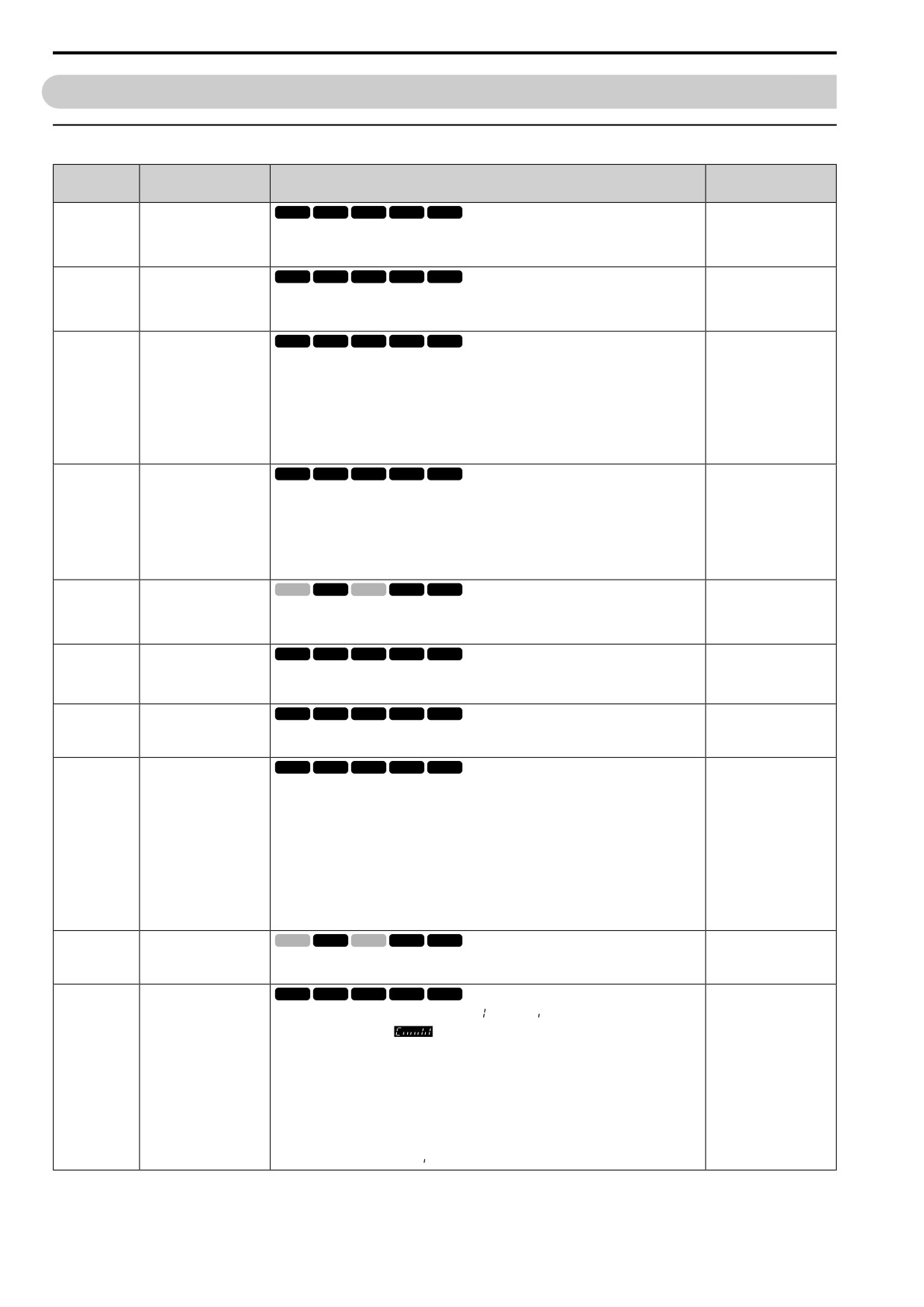
11.16 U: MONITORS
11.16
U: MONITORS
◆ U1: STATUS
No.
Name
Description
MFAO Signal Level
(Hex.)
U1-01
Frequency Reference
V/f
OLV OLV/PM AOLV/PM EZOLV
10 V = Maximum
frequency (-10 V to +10 V)
(0040)
Shows the actual frequency reference value. Parameter o1-03 [FrqDisplay Unit Selection] sets the
display units.
Unit: 0.01 Hz
U1-02
Output Frequency
V/f
OLV OLV/PM AOLV/PM EZOLV
10 V = Maximum
frequency (-10 V to +10 V)
(0041)
Shows the actual output frequency. Parameter o1-03 [FrqDisplay Unit Selection] sets the display
units.
Unit: 0.01 Hz
U1-03
Output Current
V/f
OLV OLV/PM AOLV/PM EZOLV
10 V = Drive rated current
(0042)
Shows the actual output current.
The keypad shows the value of U1-03 in amperes (A). When looking at the monitor through
Modbus communications, the current is “8192 = drive rated current (A)”. Calculate the current
from the monitor value that is in at Modbus communications using “Numerals being displayed /
8192 × drive rated current (A).
Unit: When the drive model changes, the display units for this parameter also change.
•
0.01 A units: 2001 to 2042, B001 to B018, 4001 to 4023
•
0.1A units: 2056 to 2082, 4031 to 4060
U1-04
Control Method
V/f
OLV OLV/PM AOLV/PM EZOLV
No signal output available
(0043)
Shows the drive control method.
0 : V/f Control
2 : OLVector
5 : PM OLVector
6 : PM AOLVector
8 : EZ Vector
U1-05
Motor Speed
V/f
OLV OLV/PM AOLV/PM EZOLV
10 V = Maximum
frequency (-10 V to +10 V)
(0044)
Shows the actual detected motor speed. Parameter o1-03 [FrqDisplay Unit Selection] sets the
display units.
Unit: 0.01 Hz
U1-06
Output Voltage Ref
V/f
OLV OLV/PM AOLV/PM EZOLV
200 V class: 10 V = 200
Vrms
(0045)
Shows the output voltage reference.
400 V class: 10 V = 400
Unit: 0.1 V
Vrms
U1-07
DC Bus Voltage
V/f
OLV OLV/PM AOLV/PM EZOLV
200 V class: 10 V = 400 V
(0046)
Shows the DC bus voltage.
400 V class: 10 V = 800 V
Unit: 1 V
U1-08
Output Power
V/f
OLV OLV/PM AOLV/PM EZOLV
10 V: Drive capacity (motor
rated power) kW
(0047)
Shows the internally-calculated output power.
(-10 V to +10 V)
Changing the setting of A1-02 [Control Method] also changes the signal level of the analog
output.
• A1-02 = 0: Drive capacity (kW)
• A1-02 = 2: Motor Rated Power (kW) [E2-11]
• A1-02 = 5, 6: PM Mot Rated Power (kW) [E5-02]
• A1-02 = 8: Motor Rated Power (kW) [E9-07]
Unit: When the drive model changes, the display units for this parameter also change.
•
0.01 A units: 2001 to 2042, B001 to B018, 4001 to 4023
•
0.1A units: 2056 to 2082, 4031 to 4060
U1-09
Torque Reference
V/f
OLV OLV/PM AOLV/PM EZOLV
10 V = Motor rated torque
(-10 V to +10 V)
(0048)
Shows the internal torque reference value.
Unit: 0.1%
V/f
OLV OLV/PM AOLV/PM EZOLV
U1-10
In Terminal Status
No signal output available
(0049)
Shows the status of the MFDO terminal where
= ON and
= OFF.
For example, U1-10 shows
when terminals DI1 and DI3 are ON.
bit0 : Terminal DI1 (MFDI 1)
bit1 : Terminal DI2 (MFDI 2)
bit2 : Terminal DI3 (MFDI 3)
bit3 : Terminal DI4 (MFDI 4)
bit4 : Terminal DI5 (MFDI 5)
bit5 : Terminal DI6 (MFDI 6)
bit6 : Terminal DI7 (MFDI 7)
bit7 : Not used (normal value of [
]).
392
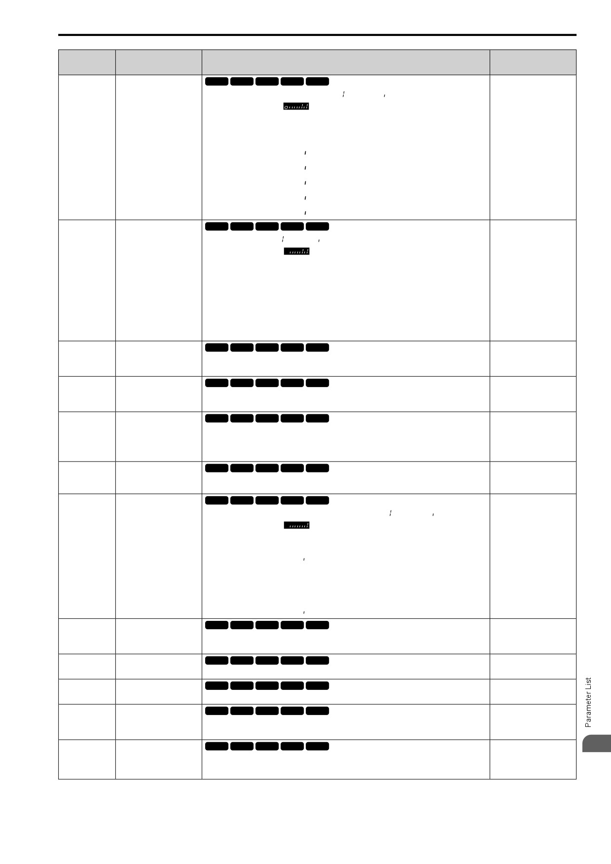
11.16 U: MONITORS
No.
Name
Description
MFAO Signal Level
(Hex.)
U1-11
Out Terminal Status
V/f
OLV OLV/PM AOLV/PM EZOLV
No signal output available
(004A)
Shows the status of the MFDO terminal where
= (ON) and
= (OFF).
For example, U1-11 shows
when terminals NO and DO2 are ON.
bit0 : Terminal NO/NC-CM
bit1 : Terminal DO1-O1C
bit2 : Terminal DO2-O2C
bit3 : Not used (normal value of [
]).
bit4 : Not used (normal value of [
]).
bit5 : Not used (normal value of [
]).
bit6 : Not used (normal value of [
]).
bit7 : Not used (normal value of [
]).
U1-12
Drive Status
V/f
OLV OLV/PM AOLV/PM EZOLV
No signal output available
(004B)
Shows drive status where
= ON and
= OFF.
For example, U1-12 shows
during run with the Reverse Run command.
bit0 : During Run
bit1 : During zero-speed
bit2 : During reverse
bit3 : During fault reset signal input
bit4 : During speed agreement
bit5 : Drive Ready
bit6 : During minor fault detection
bit7 : During fault detection
U1-13
Terminal AI1 InputLv
V/f
OLV OLV/PM AOLV/PM EZOLV
10 V = 100% (-10 V to +10
V)
(004E)
Shows the signal level of terminal AI1.
Unit: 0.1%
V/f
OLV OLV/PM AOLV/PM EZOLV
U1-14
Terminal AI2 InputLv
10 V = 100% (-10 V to +10
V)
(004F)
Shows the signal level of terminal AI2.
Unit: 0.1%
U1-16
SFS Output Frequency
V/f
OLV OLV/PM AOLV/PM EZOLV
10 V = Maximum
frequency (-10 V to +10 V)
(0053)
Shows the output frequency after soft start. Shows the frequency with acceleration and
deceleration times and S-curves. Parameter o1-03 [FrqDisplay Unit Selection] sets the display
units.
Unit: 0.01 Hz
V/f
OLV OLV/PM AOLV/PM EZOLV
U1-18
oPE Fault Parameter
No signal output available
(0061)
Shows the parameter number that caused the oPE02 [Parameter Range Setting Error] or oPE08
[Parameter Selection Error].
U1-19
Modbus Err.Code
V/f
OLV OLV/PM AOLV/PM EZOLV
No signal output available
(0066)
Shows the contents of the Modbus communication error where
=”error” and
= “no error”.
For example, U1-19 shows
when the drive detects a CRC error.
bit0 : CRC Error
bit1 : Data Length Error
bit2 : Not used (normal value of [
]).
bit3 : Parity Error
bit4 : Overrun Error
bit5 : Framing Error
bit6 : Timed Out
bit7 : Not used (normal value of [
]).
U1-24
Input Pulse Monitor
V/f
OLV OLV/PM AOLV/PM EZOLV
Determined by H6-02
(007D)
Shows the frequency to pulse train input terminal PI.
Unit: 1 Hz
U1-25
SoftNumber Flash
V/f
OLV OLV/PM AOLV/PM EZOLV
No signal output available
(004D)
Shows the ID.
U1-26
SoftNumber ROM
V/f
OLV OLV/PM AOLV/PM EZOLV
No signal output available
(005B)
Shows the ROM ID.
U1-50
Virt. Analog Input
V/f
OLV OLV/PM AOLV/PM EZOLV
Determined by H7-40
(1199)
Shows the virtual analog input value.
Expert
U1-91
Output Voltage
V/f
OLV OLV/PM AOLV/PM EZOLV
200 V class: 10 V = 200
11
Vrms
(154E)
Shows the drive internal output voltage reference.
400 V class: 10 V = 400
Expert
Unit: 0.1 V
Vrms
393