Q2V Driving Quality. Technical Manual (Item code: Q2V-Axxxx-xxx, 2020) - page 8
8.4 Replace Cooling Fans
CAUTION! Burn Hazard. Do not touch a hot drive heatsink. De-energize the drive, wait for a minimum of 15 minutes, then make
sure that the heatsink is cool before you replace the cooling fans. If you touch a hot drive heatsink, it can burn you.
NOTICE: Use the instructions in this manual to replace the cooling fans. When you do maintenance on the fans, replace all the
fans to increase product life. If you install the fans incorrectly, it can cause damage to the drive.
■ Remove a Fan
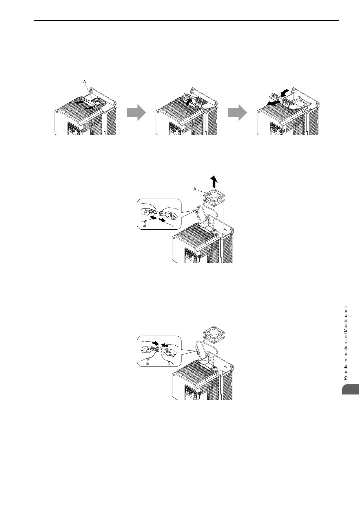
1. Push the tabs toward the back of the drive and pull up to remove the fan finger guard from the drive.
A-
Fan finger guard
Figure 8.10 Remove
the
Fan Finger Guard
2. Pull the cooling fan straight up from the drive. Disconnect the power supply connector and remove the fan
from the drive.
A - Cooling fan
Figure 8.11 Remove the Cooling
Fan
■ Install the Cooling Fans
Reverse the removal procedure to install a cooling fan.
1. Connect the power supply connector between the drive and cooling fan.
8
Figure 8.12 Connecting the power supply connector
277
8.4 Replace Cooling Fans
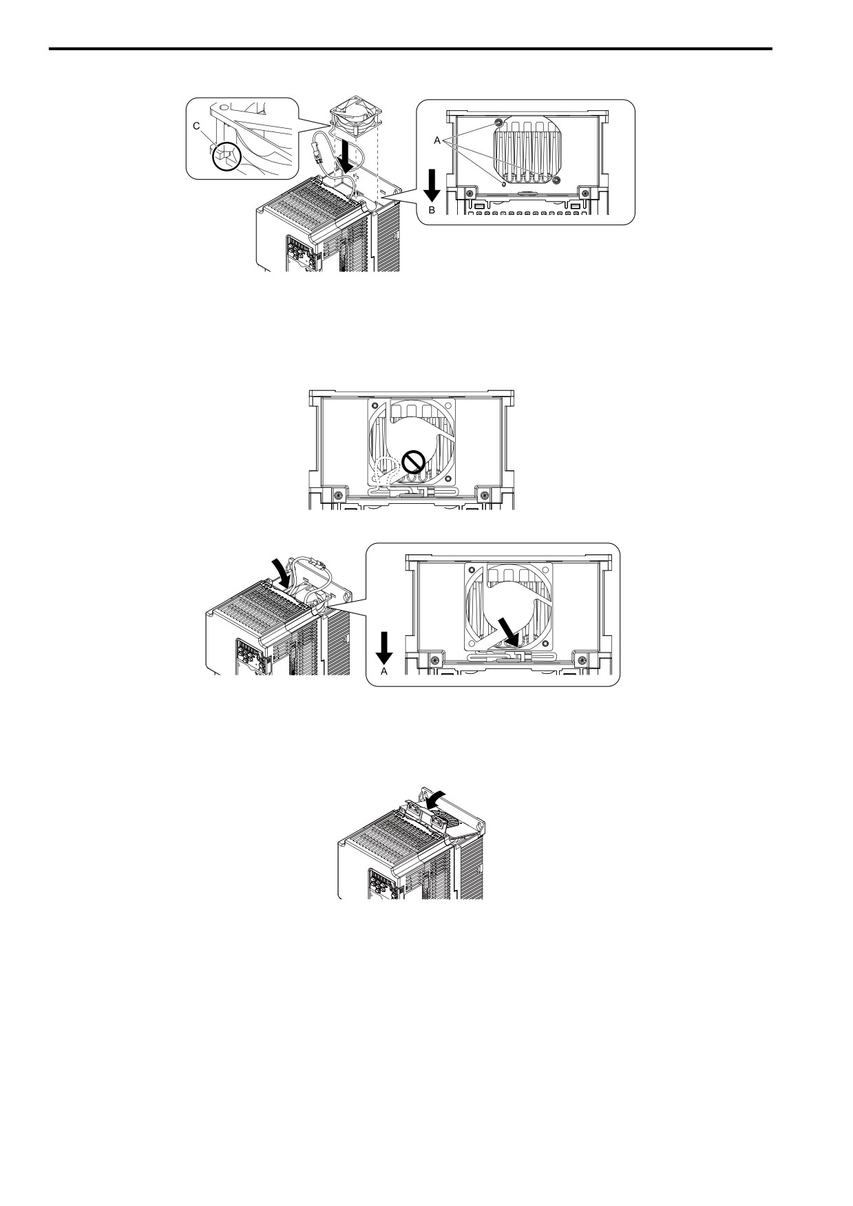
2. Install the cooling fans so that they align with the pins on the drive.
A - Alignment pins on drive
C - Notches
B - Front of drive
Figure 8.13 Installing the cooling fans
Note:
When you install the cooling fan, make sure that you do not pinch cables between the cooling fan and the drive.
3. Put the cable and connector in
the
recess
of
the drive.
A - Front of drive
Figure 8.14 Putting the cable
and
connector
in
the
recess
4. Insert the tabs of the fan cover into the holes in the
drive
and
press
in the
fan
cover until the hook clicks
into place.
Figure 8.15 Reattach
the
Fan
Finger Guard
5. Energize the drive and set o4-03 = 0 [Fan.Oper
Setting =
0 h] to reset the cooling fan operation time.
278
8.5 Replace the Drive
8.5
Replace the Drive
◆ About the Control Circuit Board
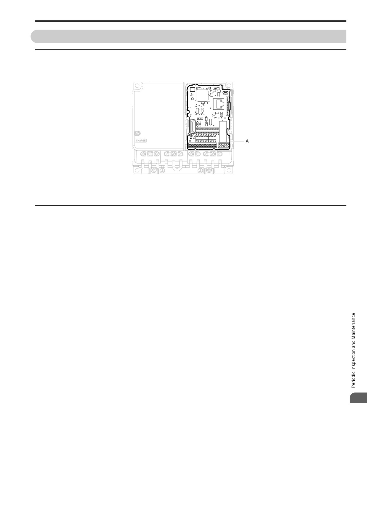
You can remove the control circuit board of the drive and install a new board. If there is a failure in the drive, you
can use this feature to easily replace the control circuit board.
A - Control circuit board
Figure 8.16 Control Circuit Terminal Block
◆ Replace the Drive
DANGER! Electrical Shock Hazard. Disconnect all power to the drive and wait for the time specified on the warning label before
you remove covers. Check the drive for dangerous voltages before servicing or repair work. If you do work on the drive when it
is energized and there is no cover over the electronic circuits, it will cause serious injury or death from electrical shock. The
drive has internal capacitors that stay charged after you de-energize the drive.
DANGER! Electrical Shock Hazard. Do not examine, connect, or disconnect wiring on an energized drive. Before servicing,
disconnect all power to the equipment and wait for the time specified on the warning label at a minimum. The internal capacitor
stays charged after the drive is de-energized. The charge indicator LED extinguishes when the DC bus voltage decreases
below 50 Vdc. When all indicators are OFF, measure for dangerous voltages to make sure that the drive is safe. If you do work
on the drive when it is energized, it will cause serious injury or death from electrical shock. The drive has internal capacitors that
stay charged after you de-energize the drive.
WARNING! Electrical Shock Hazard. Only let approved personnel install, wire, maintain, examine, replace parts, and repair the
drive. If personnel are not approved, it can cause serious injury or death.
NOTICE: When you touch the drive and circuit boards, make sure that you observe correct electrostatic discharge (ESD)
procedures. If you do not follow procedures, it can cause ESD damage to the drive circuitry.
■ Notes on Wiring the Main Circuit Terminal Block
Read these notes before you wire the main circuit terminal block.
• Use UL-Listed, vinyl-coated insulated copper wires for operation with a continuous maximum permitted
temperature of 75 °C at 600 V.
• Remove all unwanted objects that are near the terminal block connections.
• Remove the insulation from the connection wires to the wire stripping lengths shown in the manual.
• Do not use bent or crushed wires. Remove the damaged end of the wire before you use it. Incorrect connections
can cause death or serious injury from fire.
• Do not solder stranded wire. Soldered wire connections can become loose over time and cause unsatisfactory
drive performance.
8
• If you use stranded wire, make sure that all of the wire strands are in the connection. Also, do not twist the
stranded wire too much. Incorrect connections can cause death or serious injury from fire.
• Put the wire all the way into the terminal block. Remove the insulation from the wire to the recommended wire
stripping length to fit the wire with insulation in the plastic housing.
• Use a torque driver, torque ratchet, or torque wrench for the screws. A slotted driver or a hex tool will be
necessary to wire the screw clamp terminal. Use applicable tools as specified by the recommended conditions in
the product manual.
• If you use power tools to tighten the terminal screws, use a low speed setting (300 to 400 r/min). Failure to obey
can cause damage to the terminal screws.
• Wire gauges on existing drive models to be replaced may not match wire gauge ranges on new drives. Refer to
the drive manuals for correct wire sizes.
279
8.5 Replace the Drive
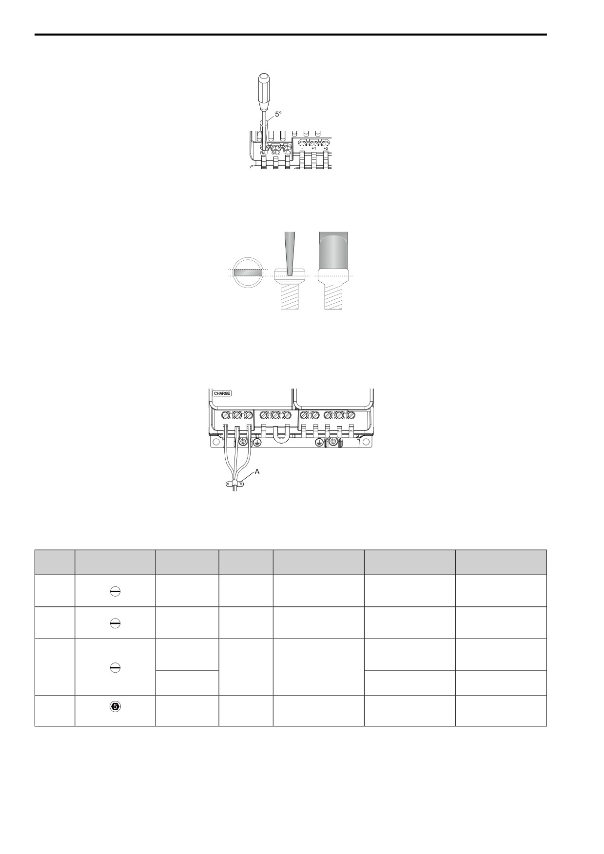
• Do not tighten the terminal screws at an angle
of 5 degrees or more. Failure to obey can cause damage to the
terminal screws.
Figure 8.17 Permitted Angle
• Put the bit all the way into the hex socket to tighten
the hex socket cap screw.
• When you tighten slotted screws, hold the straight-edge
screwdriver
perpendicularly to the screw. Make sure
that you align the end of the straight-edge screwdriver with the
screw groove.
Figure 8.18 Tightening Slotted Screws
• After connecting the wires to the terminal block, lightly
pull on the wires to make sure that they do not come out
of the terminals.
• Do not let strain on the wiring cause damage. Use a strain relief near the wiring to release the tension. Refer to
Figure 8.19 for an example.
A - Cable clamp
Figure 8.19 Strain Relief Example
Table 8.13 Recommended Wiring Tools
Screw
Bit Model
Torque Driver Model
Torque Wrench
Screw Shape
Wire Gauge
Adapter
Size
(Manufacturer)
(Tightening Torque)
(Tightening Torque)
TSD-M 1,2NM
SF-BIT-SL 0,5X3,0-70
M3
-
Bit
(0.3 - 1.2 N∙m
-
(PHOENIX CONTACT)
(2.7 - 10.6 in∙lb))
TSD-M 3NM
SF-BIT-SL 1,0X4,0-70
M4
-
Bit
(1.2 - 3.0 N∙m
-
(PHOENIX CONTACT)
(10.6 - 26.6 in∙lb))
TSD-M 3NM
≤ 25 mm2
(1.2 - 3.0 N∙m
-
(AWG 10)
SF-BIT-SL 1,2X6,5-70
(10.6 - 26.6 in∙lb))
M5 *1
Bit
(PHOENIX CONTACT)
≥ 30 mm2
4.1 - 4.5 N∙m
-
(AWG 8)
(36.3 - 39.8 in∙lb) *2 *3
SF-BIT-HEX 5-50
5 - 9 N∙m
M6
-
Bit
-
(PHOENIX CONTACT)
(44.3 - 79.7 in∙lb) *2 *3
(WAF: 5 mm)
*1
When you wire drive models 2042, 2056, 4031, 4038, 4044, and 4060, select the correct tools for the wire gauge.
*2
Use 6.35 mm (0.25 in) bit socket holder.
*3
Use a torque wrench that can apply this torque measurement range.
280
8.5 Replace the Drive
■ Remove the Control Circuit Board
Remove the front cover and keypad from the drive.
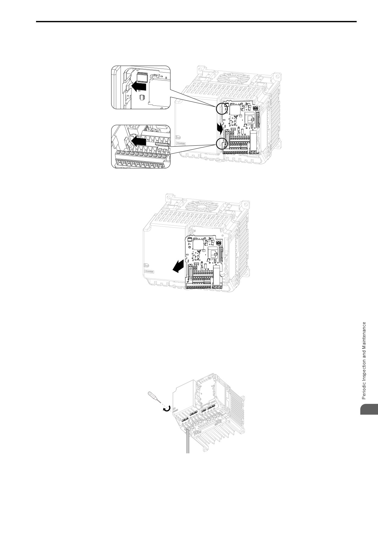
1. Push the tabs to the left that hold the control board to the drive.
Figure 8.20
Unhook
the
Tabs
2.
Pull the
left
side of the control
circuit board out first.
Figure 8.21 Remove the Control Circuit Board
■ Put the Control Circuit Board in a New Drive
Remove the keypad, front cover, and control circuit board of the new drive.
Wire the main circuit terminals of the new drive, then attach the wired control circuit board.
1. Wire the main circuit terminals.
Note:
To wire terminals +1 and +2, remove the jumper between terminals +1 and +2.
8
Figure 8.22 Wire the Main Circuit Terminals
2. Attach the wired control circuit board to the drive.
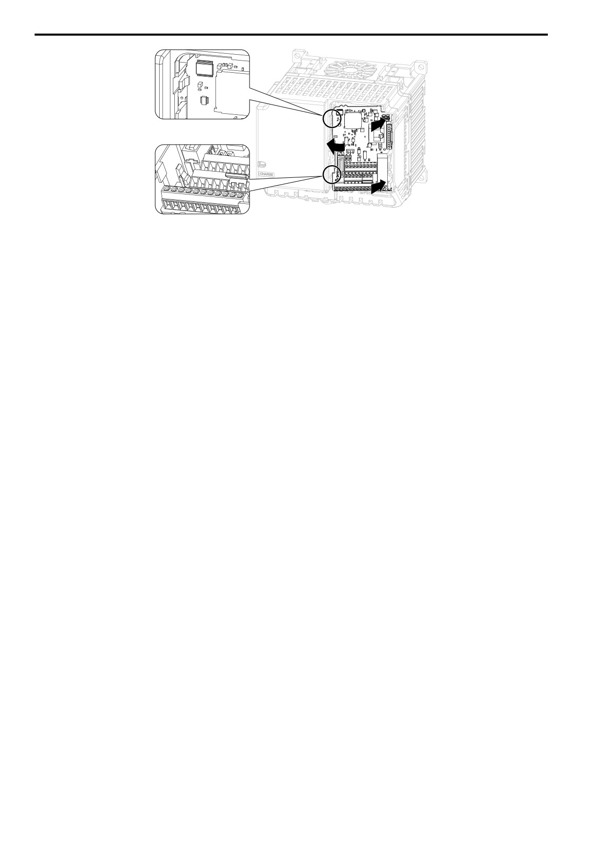
Push the control circuit board until the hooks click into place on the drive.
281
8.5 Replace the Drive
Figure 8.23
Attach the
Control
Circuit Board
3.
Attach
the
keypad and
front cover to the new
drive.
4. Energize the
drive and
set these parameters:
• o2-04 [Drive KVA
Selection]: Set this parameter to the
model number of the new drive.
•
o4-01 to
o4-13 [Maintenance Period]: Reset the performance life monitors for the components.
282
8.6 Storage Guidelines
8.6
Storage Guidelines
The chemicals in the electrolytic capacitors and other electronic parts of the drive change over time. When you
store the drive for long periods of time, use the information in this section to help keep the performance life
estimates.
◆ Storage Location
• Temperature and Humidity
When you store the drive for approximately one month, for example during shipping, you can put the drive in a
location where the temperature is -20 °C to +70 °C (-4 °F to +158 °F). Correctly package and store the drive
during shipping to prevent vibration and impact damage.
Do not put the drive in direct sunlight or where there will be condensation or ice. Put the drive in a location
where the relative humidity is 95% or less.
• Dust and Oil Mist
Do not keep the drive locations with dust or oil mist. For example, cement factories and cotton mills.
• Corrosive Gas
Do not keep the drive in locations with corrosive gas. For example, chemical plants, refineries, and sewage
plants.
• Salt Damage
Do not keep the drive in salty locations. For example, locations near the ocean, and salt damage-designated
locations.
Do not keep the drive in unsatisfactory locations. Keep all drives in storage rooms that are safe from
unsatisfactory elements.
◆ Regular Application of Power
To prevent deterioration of the capacitors, the manufacturer recommends that you apply power to the drive a
minimum of one time each year for a minimum of 30 minutes.
If you store the drive for longer than two years and do not apply power, the manufacturer recommends that you
use a variable power source and gradually increase the power from 0 V to the rated drive voltage over a period of
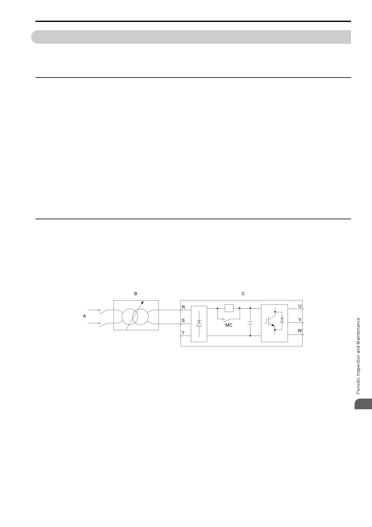
2 to 3 minutes. Apply power for a minimum of 1 hour with no load to reform the main circuit electrolytic
capacitor. When you operate the drive after you apply power, wire the drive correctly and check for drive faults,
overcurrents, motor vibration, motor speed differences, and other defects during operation.
A - AC power supply
C - Drive
B - Variable power source
Figure 8.24 Power Distribution Method
8
283
8.6 Storage Guidelines
284
9
Disposal
9.1
Safety Precautions
286
9.2
Disposal Instructions
287
9.3
WEEE Directive
288
285
9.1 Safety Precautions
9.1
Safety Precautions
WARNING
Electrical Shock Hazard
De-energize the drive and wait 5 minutes minimum until the Charge LED turns off. Remove the
front cover and terminal cover to do work on wiring, circuit boards, and other parts. Use
terminals for their correct function only.
Incorrect wiring, incorrect ground connections, and incorrect repair of protective covers can cause death or
serious injury.
Only let approved personnel install, wire, maintain, examine, replace parts, and repair the drive.
If personnel are not approved, it can cause serious injury or death.
Do not wear loose clothing or jewelry when you do work on the drive. Tighten loose clothing
and remove all metal objects, for example watches or rings.
Loose clothing can catch on the drive and jewelry can conduct electricity and cause serious injury or death.
Crush Hazard
Wear eye protection when you do work on the drive.
If you do not use correct safety equipment, it can cause serious injury or death.
CAUTION
Crush Hazard
Tighten terminal cover screws and hold the case safely when you move the drive.
If the drive or covers fall, it can cause moderate injury.
286
9.2 Disposal Instructions
9.2
Disposal Instructions
Correctly dispose of the drive and packing material as specified by applicable regional, local, and municipal laws
and regulations.
9
287
9.3 WEEE Directive
9.3
WEEE Directive
The wheelie bin symbol on this product, its manual, or its packaging identifies that you must recycle it at the end
of its product life.
You must discard the product at an applicable collection point for electrical and electronic equipment (EEE). Do
not discard the product with usual waste.
288
10
Specifications
10.1
Safety Precautions
290
10.2
Drive Duty Modes
291
10.3
Model Specifications (Three-Phase 200 V Class)
292
10.4
Model Specifications (Single-Phase 200 V Class)
295
10.5
Model Specifications (Three-Phase 400 V Class)
296
10.6
Drive Specifications
298
10.7
Drive Derating
301
10.8
Drive Models and Drive Watt Loss
304
10.9
Drive Exterior and Mounting Dimensions
307
10.10 Peripheral Devices and Options
311
289
10.1 Safety Precautions
10.1
Safety Precautions
DANGER
Do not ignore the safety messages in this manual.
If you ignore the safety messages in this manual, it will cause serious injury or death. The manufacturer is not
responsible for injuries or damage to equipment.
290
10.2 Drive Duty Modes
10.2
Drive Duty Modes
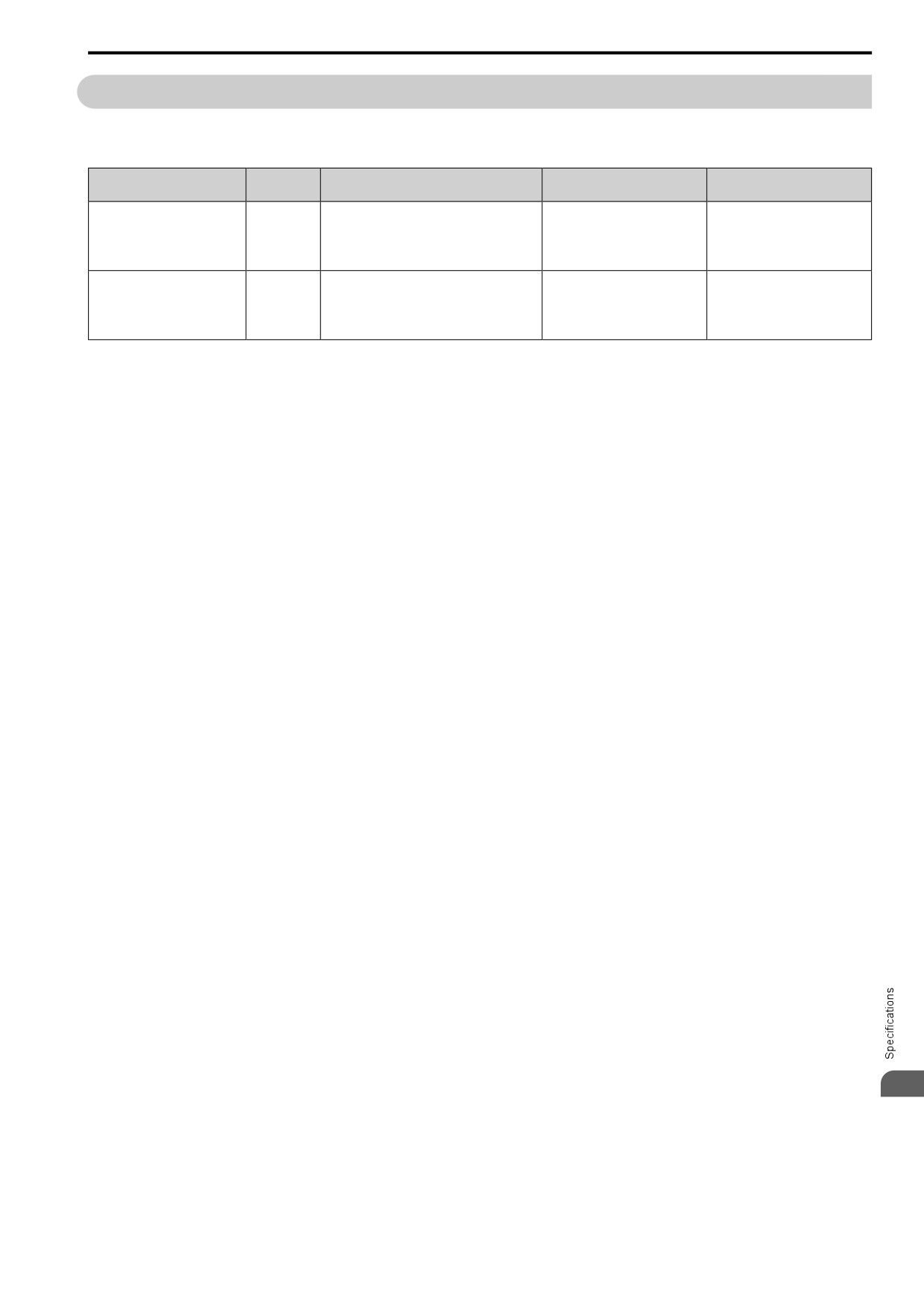
The drive has two duty modes from which to select for the application: Heavy Duty (HD) and Normal Duty (ND).
Table 10.1 Drive Duty Modes
C6-01
Overload Tolerance (oL2
Duty Rating
Application
Default Carrier Frequency
Setting
[Drive Overload])
• Extruder
150% of the rated output current for
Heavy Duty Rating
• Conveyor
60 seconds The permitted
0
Determined by o2-04, A1-02
(HD)
• Cranes and hoists
frequency of overload is once every
10 minutes.
• Constant torque or high overload capacity
• Fan
110% of the rated output current for
Normal Duty Rating
• Pump
60 seconds The permitted
1
Determined by o2-04, A1-02
(ND)
• Blower
frequency of overload is once every
10 minutes.
• Variable speed control
10
291
10.3 Model Specifications (Three-Phase 200 V Class)
10.3
Model Specifications (Three-Phase 200 V Class)
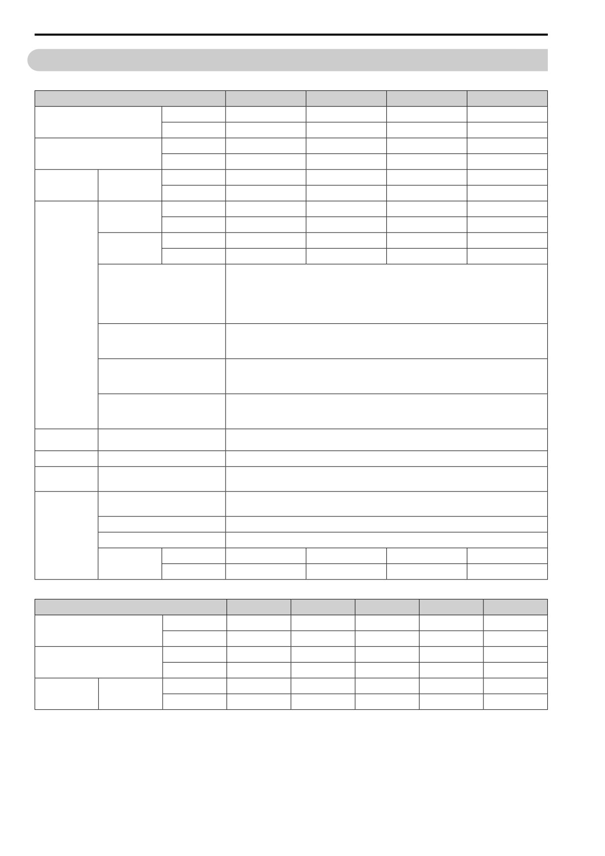
Table 10.2 Ratings (Three-Phase 200 V Class)
Model
2001
2002
2004
2006
HD *1
0.1
0.25
0.55
1.1
Maximum Applicable Motor Output (kW)
ND *2
0.18
0.37
0.75
1.1
HD *1
1/6
1/4
1/2
1
Maximum Applicable Motor Output (HP)
ND *2
1/6
1/4
3/4
1.5
HD
0.7
1.5
2.9
5.8
Rated Input Current
Input
(A)
ND
1.1
1.9
3.9
7.3
HD
0.3
0.6
1.1
1.9
Rated Output
Capacity (kVA) *3
ND
0.5
0.7
1.3
2.3
HD
0.8
1.6
3.0
5.0
Rated Output
Current (A)
ND
1.2
1.9
3.5
6
• HD: 150% of the rated output current for 60 seconds. The permitted frequency of overload is once every 10
minutes.
• ND: 110% of the rated output current for 60 seconds. The permitted frequency of overload is once every
10
Overload Tolerance
minutes.
Note:
Output
Derating may be necessary for applications that start and stop frequently.
HD: 10 kHz without derating the drive capacity.
Carrier Frequency
ND: 2 kHz without derating the drive capacity.
Derate the drive capacity to use values to 15 kHz maximum.
Three-phase 200 V to 240 V
Maximum Output Voltage
Note:
The maximum output voltage is proportional to the input voltage.
• EZ Vector: 120 Hz
Maximum Output Frequency
• PM AOLVector: 270 Hz
• V/f Control, OLVector, PM OLVector: 590 Hz
Measures for
DC reactor
External options
Harmonics
Braking Device
Braking Transistor
Standard internal characteristics
EMC Filter
EMC Filter
Category C3 (Conducted emission)
IEC61800-3
• Three-phase AC power supply 200 V to 240 V at 50/60 Hz
Rated Voltage/Rated Frequency
• DC power supply 270 V to 340 V
Permitted Voltage Fluctuation
-15% to +10%
Power Supply
Permitted Frequency Fluctuation
±5%
HD
0.3
0.7
1.3
2.7
Input Power (kVA)
ND
0.5
1.2
1.8
3.3
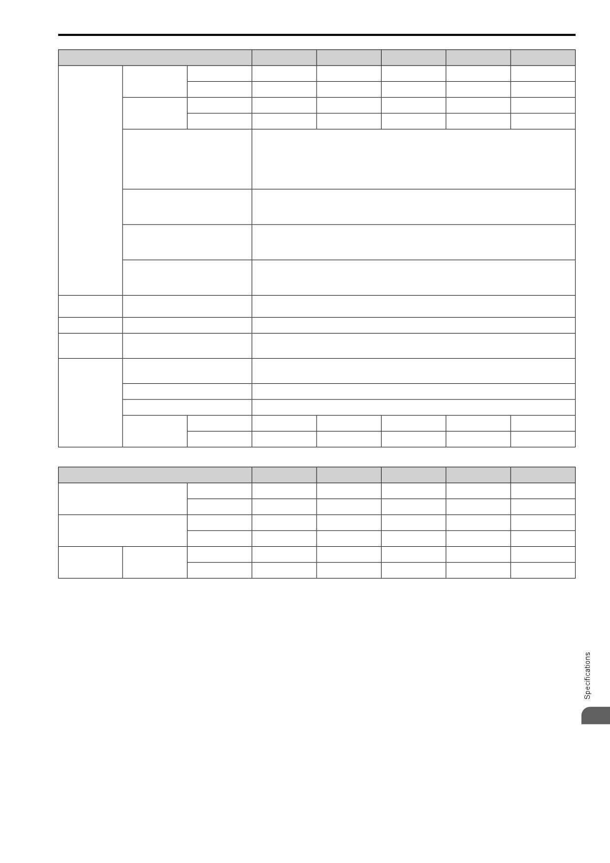
Table 10.3 Ratings (Three-Phase 200 V Class)
Model
2008
2010
2012
2018
2021
HD *1
1.1
1.5
2.2
3
4.0
Maximum Applicable Motor Output (kW)
ND *2
1.5
2.2
3
3.7
5.5
HD *1
1.5
2
3
4
5
Maximum Applicable Motor Output (HP)
ND *2
2
3
4
5
5
HD
7.0
7.5
11
15.6
18.9
Rated Input Current
Input
(A)
ND
8.8
10.8
13.9
18.5
24
292
10.3 Model Specifications (Three-Phase 200 V Class)
Model
2008
2010
2012
2018
2021
HD
2.6
3
4.2
5.3
6.7
Rated Output
Capacity (kVA) *3
ND
3
3.7
4.6
6.7
8
HD
6.9
8.0
11.0
14.0
17.6
Rated Output
Current (A)
ND
8
9.6
12.2
17.5
21
• HD: 150% of the rated output current for 60 seconds. The permitted frequency of overload is once every
10 minutes.
• ND: 110% of the rated output current for 60 seconds. The permitted frequency of overload is once every
Overload Tolerance
10 minutes.
Note:
Output
Derating may be necessary for applications that start and stop frequently.
HD: 8 kHz without derating the drive capacity.
Carrier Frequency
ND: 2 kHz without derating the drive capacity.
Derate the drive capacity to use values to 15 kHz maximum.
Three-phase 200 V to 240 V
Maximum Output Voltage
Note:
The maximum output voltage is proportional to the input voltage.
• V/f Control, OLVector, PM OLVector: 590 Hz
Maximum Output Frequency
• PM AOLVector: 270 Hz
• EZ Vector: 120 Hz
Measures for
DC reactor
External options
Harmonics
Braking Device
Braking Transistor
Standard internal characteristics
EMC Filter
EMC Filter
Category C3 (Conducted emission)
IEC61800-3
• Three-phase AC power supply 200 V to 240 V at 50/60 Hz
Rated Voltage/Rated Frequency
• DC power supply 270 V to 340 V
Permitted Voltage Fluctuation
-15% to +10%
Power Supply
Permitted Frequency Fluctuation
±5%
HD
3.2
3.4
5.0
7.1
8.7
Input Power (kVA)
ND
4.0
4.9
6.4
8.5
11
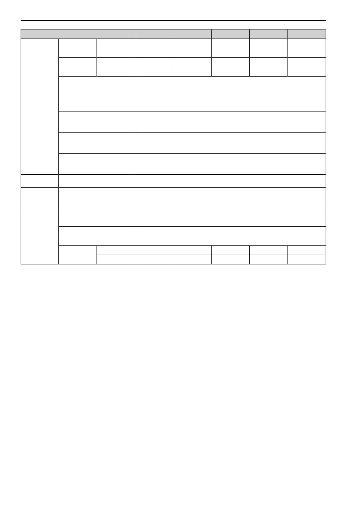
Table 10.4 Ratings (Three-Phase 200 V Class)
Model
2030
2042
2056
2070
2082
HD *1
5.5
7.5
11
15
18.5
Maximum Applicable Motor Output (kW)
ND *2
7.5
11
15
18.5
22
HD *1
7.5
10
15
20
25
Maximum Applicable Motor Output (HP)
ND *2
10
10
20
25
30
HD
24
37
52
68
96
Rated Input Current
Input
(A)
ND
37
52
68
80
114
10
293
10.3 Model Specifications (Three-Phase 200 V Class)
Model
2030
2042
2056
2070
2082
HD
9.5
12.6
17.9
22.9
28.6
Rated Output
Capacity (kVA) *3
ND
11.4
16
21.3
26.7
31.2
HD
25.0
33.0
47.0
60.0
75.0
Rated Output
Current (A)
ND
30
42
56
70
82
• HD: 150% of the rated output current for 60 seconds. The permitted frequency of overload is once every
10 minutes.
• ND: 110% of the rated output current for 60 seconds. The permitted frequency of overload is once every
Overload Tolerance
10 minutes.
Note:
Output
Derating may be necessary for applications that start and stop frequently.
HD: 8 kHz without derating the drive capacity.
Carrier Frequency
ND: 2 kHz without derating the drive capacity.
Derate the drive capacity to use values to 15 kHz maximum.
Three-phase 200 V to 240 V
Maximum Output Voltage
Note:
The maximum output voltage is proportional to the input voltage.
• V/f Control, OLVector, PM OLVector: 590 Hz
Maximum Output Frequency
• PM AOLVector: 270 Hz
• EZ Vector: 120 Hz
Measures for
DC reactor
External options
Harmonics
Braking Device
Braking Transistor
Standard internal characteristics
EMC Filter
EMC Filter
Category C3 (Conducted emission)
IEC61800-3
• Three-phase AC power supply 200 V to 240 V at 50/60 Hz
Rated Voltage/Rated Frequency
• DC power supply 270 V to 340 V
Permitted Voltage Fluctuation
-15% to +10%
Power Supply
Permitted Frequency Fluctuation
±5%
HD
11.0
17.0
24.0
31.0
44.0
Input Power (kVA)
ND
17.0
24.0
31.0
37.0
52.0
*1
The maximum applicable motor output complies with 208 V motor ratings as specified in NEC Table 430.250. The rated output
current of the drive output amps must be equal to or more than the motor rated current.
*2
The maximum applicable motor output is based on 4-pole, general-purpose 220 V motor ratings. The rated output current of the
drive output amps must be equal to or more than the motor rated current.
*3
The rated output capacity is calculated with a rated output voltage of 220 V.
294
10.4 Model Specifications (Single-Phase 200 V Class)
10.4
Model Specifications (Single-Phase 200 V Class)
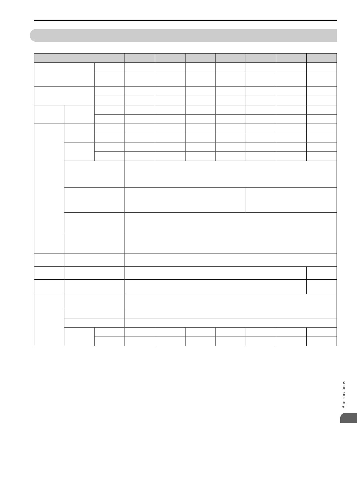
Table 10.5 Ratings (Single-Phase 200 V Class)
Model
B001
B002
B004
B006
B010
B012
B018
HD *1
0.1
0.25
0.55
1.1
1.5
2.2
4.0
Maximum Applicable Motor
Output (kW)
0.2
ND *2
0.37
0.75
1.1
2.2
3.0
-
0.18
HD *1
1/6
1/4
1/2
1
2
3
5
Maximum Applicable Motor
Output (HP)
ND *2
1/6
1/4
3/4
1.5
3
3
-
HD
1.4
2.8
5.5
11
14.1
20.6
35.0
Rated Input
Input
Current (A)
ND
2.0
5.0
7.3
13.8
20.2
24.0
-
Rated Output
HD
0.3
0.6
1.1
1.9
3
4.2
6.7
Capacity (kVA)
*3
ND
0.5
0.7
1.3
2.3
3.7
4.6
-
HD
0.8
1.6
3
5
8
11
17.6
Rated Output
Current (A)
ND
1.2
1.9
3.5
6
9.6
12.2
-
• HD: 150% of the rated output current for 60 seconds. The permitted frequency of overload is once every 10 minutes.
• ND: 110% of the rated output current for 60 seconds. The permitted frequency of overload is once every 10 minutes.
Overload Tolerance
Note:
Derating may be necessary for applications that start and stop frequently.
Output
HD: 8 kHz without derating the drive capacity.
HD: 10 kHz without derating the drive capacity.
Carrier Frequency
ND: 2 kHz without derating the drive capacity.
ND: 2 kHz without derating the drive capacity.
Derate the drive capacity to use values to 15 kHz
Derate the drive capacity to use values to 15 kHz maximum.
maximum.
Single-phase 200 V to 240 V
Maximum Output Voltage
Note:
The maximum output voltage is proportional to the input voltage.
• V/f Control, OLVector, PM OLVector: 590 Hz
Maximum Output Frequency
• PM AOLVector: 270 Hz
• EZ Vector: 120 Hz
Measures for
AC reactor
External options
Harmonics
External
Braking Device
Braking Transistor
Standard internal characteristics
options
EMC Filter
External
EMC Filter
Category C1 (Conducted emission)
IEC61800-3
options
• Single-phase AC power supply 200 V to 240 V at 50/60 Hz
Rated Voltage/Rated Frequency
• DC power supply 270 V to 340 V
Permitted Voltage Fluctuation
-15% to +10%
Power Supply
Permitted Frequency Fluctuation
±5%
HD
0.4
0.7
1.5
2.9
3.7
5.4
9.2
Input Power
(kVA)
ND
0.5
1.3
1.9
3.6
5.3
6.3
-
*1
The maximum applicable motor output complies with 208 V motor ratings as specified in NEC Table 430.250. The rated output
current of the drive output amps must be equal to or more than the motor rated current.
*2
The maximum applicable motor output is based on 4-pole, general-purpose 220 V motor ratings. The rated output current of the drive
output amps must be equal to or more than the motor rated current.
*3
The rated output capacity is calculated with a rated output voltage of 220 V.
10
295
10.5 Model Specifications (Three-Phase 400 V Class)
10.5
Model Specifications (Three-Phase 400 V Class)
Table 10.6 Ratings (Three-Phase 400 V Class)
Model
Duty Rating
4001
4002
4004
4005
4007
4009
4012
HD
0.37
0.55
1.1
1.5
2.2
3.0
4.0
Maximum Applicable Motor
Output *1 (kW)
ND
0.37
0.75
1.5
2.2
3.0
4.0
5.5
HD
1/2
3/4
2
3
3
4
5
Maximum Applicable Motor
Output *1 (HP)
ND
1/2
1
2
3
4
5
7.5
HD
1.2
1.8
3.2
4.4
6.0
8.2
10.4
Rated Input
Input
Current (A)
ND
1.2
2.1
4.3
5.9
8.1
9.4
14
Rated Output
HD
0.9
1.4
2.6
3.7
4.3
5.6
7
Capacity *2
(kVA)
ND
0.9
1.6
3.1
4.1
5.4
6.8
9.1
HD
1.2
1.8
3.4
4.8
5.6
7.3
9.2
Rated Output
Current (A)
ND
1.2
2.1
4.1
5.4
7.1
8.9
11.9
• HD: 150% of the rated output current for 60 seconds. The permitted frequency of overload is once every 10 minutes.
• ND: 110% of the rated output current for 60 seconds. The permitted frequency of overload is once every 10 minutes.
Overload Tolerance
Note:
Derating may be necessary for applications that start and stop frequently.
Output
HD: 8 kHz without derating the drive capacity.
Carrier Frequency
ND: 2 kHz without derating the drive capacity.
Derate the drive capacity to use values to 15 kHz maximum.
Three-phase 380 V to 480 V
Maximum Output Voltage
Note:
The maximum output voltage is proportional to the input voltage.
• V/f Control, OLVector, PM OLVector: 590 Hz
Maximum Output Frequency
• PM AOLVector: 270 Hz
• EZ Vector: 120 Hz
Measures for
DC reactor
External options
Harmonics
Braking Device
Braking Transistor
Standard internal characteristics
EMC Filter
EMC Filter
Category C2 (Conducted emission)
IEC61800-3
Rated Voltage/Rated Frequency
Three-phase AC power supply 380 V to 480 V at 50/60 Hz
Permitted Voltage Fluctuation
-15% to +10%
Power Supply
Permitted Frequency Fluctuation
±5%
HD
1.1
1.6
2.9
4
5.5
7.5
9.5
Input Power
(kVA)
ND
1.1
1.9
3.9
5.4
7.4
8.6
13
*1
The maximum applicable motor output complies with 380 V motor ratings as specified in Annex G of IEC
60947-4-1. The rated
output current of the drive output amps must be equal to or more than the motor rated current.
*2
The rated output capacity is calculated with a rated output voltage of 440 V.
Table 10.7 Ratings (Three-Phase 400 V Class)
Model
Duty Rating
4018
4023
4031
4038
4044
4060
HD
5.5
7.5
11.0
15.0
18.5
22.0
Maximum Applicable Motor Output
*1 (kW)
ND
7.5
11.0
15.0
18.5
22.0
30.0
HD
10
10
15
20
25
30
Maximum Applicable Motor Output
*1 (HP)
ND
10
15
20
25
30
40
HD
15
20
29
39
50.5
59.7
Rated Input
Input
Current (A)
ND
20
24
38
44
59.7
80.7
296
10.5 Model Specifications (Three-Phase 400 V Class)
Model
Duty Rating
4018
4023
4031
4038
4044
4060
Rated Output
HD
11.3
13.7
18.3
23.6
29.7
34.3
Capacity *2
(kVA)
ND
13.3
17.8
23.6
29
33.5
45.7
HD
14.8
18.0
24.0
31.0
39.0
45.0
Rated Output
Current (A)
ND
17.5
23.4
31.0
38.0
44.0
60
• HD: 150% of the rated output current for 60 seconds. The permitted frequency of overload is once every 10
minutes.
• ND: 110% of the rated output current for 60 seconds. The permitted frequency of overload is once every 10
Overload Tolerance
minutes.
Note:
Output
Derating may be necessary for applications that start and stop frequently.
HD: 8 kHz without derating the drive capacity.
Carrier Frequency
ND: 2 kHz without derating the drive capacity.
Derate the drive capacity to use values to 15 kHz maximum.
Three-phase 380 V to 480 V
Maximum Output Voltage
Note:
The maximum output voltage is proportional to the input voltage.
• V/f Control, OLVector, PM OLVector: 590 Hz
Maximum Output Frequency
• PM AOLVector: 270 Hz
• EZ Vector: 120 Hz
Measures for
DC reactor
External options
Harmonics
Braking Device
Braking Transistor
Standard internal characteristics
EMC Filter
EMC Filter
Category C2 (Conducted emission)
IEC61800-3
Rated Voltage/Rated Frequency
Three-phase AC power supply 380 V to 480 V at 50/60 Hz
Permitted Voltage Fluctuation
-15% to +10%
Power Supply
Permitted Frequency Fluctuation
±5%
HD
14
18
27
36
47
55
Input Power
(kVA)
ND
18
22
35
40
55
74
*1
The maximum applicable motor output complies with 380 V motor ratings as specified in Annex G of IEC 60947-4-1. The rated
output current of the drive output amps must be equal to or more than the motor rated current.
*2
The rated output capacity is calculated with a rated output voltage of 440 V.
10
297
10.6 Drive Specifications
10.6
Drive Specifications
Note:
• To get the OLV specifications, do Rotational Auto-Tuning.
• To get the longest product life, install the drive in an environment that meets the necessary specifications.
Table 10.8 Control Characteristics
Item
Specification
• V/f Control (V/f Control)
• Open Loop Vector (OLVector)
Control Methods
• PM Open Loop Vector (PM OLVector)
• PM Advanced Open Loop Vector (PM AOLVector)
• EZ Vector Control (EZ Vector)
• V/f Control, OLVector, PM OLVector: 0.01 Hz to 590 Hz
Frequency Control
• PM AOLVector: 0.01 Hz to 270 Hz
Range
• EZ Vector: 0.01 Hz to 120 Hz
Frequency Accuracy
Digital inputs: ±0.01% of the maximum output frequency (-10 °C to +40 °C (14 °F to 104 °F))
(Temperature
Analog inputs: Within ±0.1% of the maximum output frequency (25 °C ±10 °C (77 °F ±18 °F))
Fluctuation)
Frequency Setting
Digital inputs: 0.01 Hz
Resolution
Analog inputs: 1/2048 of the maximum output frequency (11-bit signed)
Output Frequency
0.001 Hz
Resolution
Frequency Setting
Main speed frequency reference: 0 Vdc to 10 Vdc (20 kΩ), 4 mA to 20 mA (250 Ω), 0 mA to 20 mA (250
Ω)
Signal
Main speed reference: Pulse train input (maximum 32 kHz)
• V/f Control: 150%/3 Hz
• OLVector: 150%/1 Hz
• PM OLVector: 100%/5% speed
• PM AOLVector: 100%/0 min-1 (when high frequency injection is enabled)
Starting Torque
• EZ Vector: 100%/10% speed
Note:
Correctly select the drive and motor capacity for this starting torque in these control methods:
• OLVector
• PM AOLVector
• V/f Control: 1:40
• OLVector: 1:100
Speed Control Range
• PM OLVector: 1:10
• PM AOLVector: 1:100 (when high frequency injection is enabled)
• EZ Vector: 1:10
Possible in these control methods:
Zero Speed Control
• PM AOLVector
Parameter settings allow different limits in four quadrants in these control methods:
• OLVector
Torque Limits
• PM AOLVector
• EZ Vector
Acceleration and
0.0 s to 6000.0 s
Deceleration Times
The drive can set four pairs of different acceleration and deceleration times.
Approximately 20%
Approximately 125% with a dynamic braking option
• Short-time average deceleration torque
Motor output 0.1/0.2 kW: over 150%
Motor output 0.4/0.75 kW: over 100%
Motor output 1.5 kW: over 50%
Motor output 2.2 kW and larger: over 20%, Overexcitation Braking/High Slip Braking allow for approximately 40%
WARNING!
Set L3-04 = 0 [StallP@Decel Enable = Disabled] when you operate the drive with:
Braking Torque
• a regenerative converter
• regenerative unit
• braking resistor
• braking resistor unit.
If you set the parameter incorrectly, the drive can decelerate for too long and cause serious injury or death.
Note:
• Short-time average deceleration torque refers to the torque needed to decelerate the motor (uncoupled from the load) from the rated speed to zero.
Motor characteristics can change the actual specifications.
• Motor characteristics change the continuous regenerative torque and short-time average deceleration torque for motors 2.2 kW and larger.
298
10.6 Drive Specifications
Item
Specification
V/f Characteristics
Select from 15 pre-defined V/f patterns, or a user-set V/f pattern.
Feed Forward Control, Restart After Momentary Power Loss, Speed Search, Overtorque Detection, Torque Limit, 17 Step Speed (max.), Accel/Decel
Switch, S-curve Acceleration/Deceleration, 3-wire Sequence, Auto-Tuning (Rotational and Stationary), Dwell Function, Cooling Fan ON/OFF Switch,
Main Control
Slip Compensation, Torque Compensation, Frequency Jump, Upper/Lower Limits for Frequency Reference, DC Injection Braking at Start and Stop,
Functions
Overexcitation Braking, High Slip Braking, PID Control (with Sleep Function), Energy Saving Control, Modbus Communications (RS-485 max, 115.2
kbps), Auto Restart, Application Presets, Q2pack (customized functions), Parameter Backup Function, Online Tuning, KEB, Overexcitation
Deceleration, Overvoltage Suppression, High Frequency Injection, etc.
Table 10.9 Protection Functions
Item
Specification
Motor Protection
Electronic thermal overload protection
Drive stops when the output current is more than 200% of the HD output current.
Momentary
Overcurrent
Note:
Protection
Standard value is 200%. Different capacity drives have different values.
Drive stops when the output current is more than these overload tolerances:
• HD: 150% of the rated output current for 60 seconds. The permitted frequency of overload is once every 10 minutes.
Overload Protection
• ND: 110% of the rated output current for 60 seconds. The permitted frequency of overload is once every 10 minutes.
Note:
If output frequency < 6 Hz, the drive can trigger the overload protection function when the output current is in the overload tolerance range.
Overvoltage
200 V class: Stops when the DC bus voltage is more than approximately 410 V
Protection
400 V class: Stops when the DC bus voltage is more than approximately 820 V
Three-phase 200 V class: Stops when the DC bus voltage decreases to less than approximately 190 V
Undervoltage
Single-phase 200 V class: Stops when the DC bus voltage decreases to less than approximately 160 V
Protection
Three-phase 400 V class: Stops when the DC bus voltage decreases to less than approximately 380 V
Stops when power loss is longer than 15 ms and continues operation if power loss is shorter than 2 s (depending on parameter settings).
Note:
Momentary Power
• Stop time may be shortened depending on the load and motor speed.
Loss Ride-thru
• Drive capacity will change the continuous operation time. A Momentary Power Loss Recovery Unit is necessary to continue operation through a 2
s
power loss on models 2001 to 2042 and 4001 to 4023.
Heatsink Overheat
Thermistor
Protection
Braking Resistor
Overheat detection for braking resistor (optional ERF-type, 3% ED)
Overheat Protection
Stall Prevention
Stall prevention is available during acceleration, deceleration, and during run.
Electronic circuit protection
Note:
Ground Fault
Protection
This protection detects ground faults during run. The drive will not provide protection when:
• There is a low-resistance ground fault for the motor cable or terminal block
• Energizing the drive when there is a ground fault.
DC Bus Charge LED
Charge LED illuminates when DC bus voltage is more than 50 V.
Table 10.10 Environment
Item
Specification
Area of Use
Indoors
Power Supply
Overcurrent Category III
IP20/UL Open Type: -10°C to +50 °C (14 °F to 122 °F)
Ambient
IP20/UL Type 1: -10 °C to +40 °C (14 °F to 104 °F)
Temperature Setting
• When installing the drive in an enclosure, use a cooling fan or air conditioner to keep the internal air temperature in the permitted range.
• Do not let the drive freeze.
95% RH or less
Humidity
Do not let condensation form on the drive.
Storage Temperature
-20 °C to +70 °C (-4 °F to +158 °F) (short-term temperature during transportation)
Pollution degree 2 or less
Install the drive in an area without:
• Oil mist, corrosive or flammable gas, or dust
• Metal powder, oil, water, or other unwanted materials
Surrounding Area
• Radioactive materials or flammable materials, including wood
10
• Harmful gas or fluids
• Salt
• Direct sunlight
299

10.6 Drive Specifications
Item
Specification
1000 m (3281 ft) Maximum
Note:
Derate the output current by 1% for each 100 m (328 ft) to install the drive in altitudes between 1000 to 4000 m (3281 to 13123 ft).
Altitude
It is not necessary to derate the rated voltage in these conditions:
• Installing the drive at 2000 m (6562 ft) or lower
• Installing the drive between 2000 to 4000 m (6562 to 13123 ft) and grounding the neutral point on the power supply.
Contact the manufacturer or your nearest sales representative when not grounding the neutral point.
•
10 Hz to 20 Hz: 1 G (9.8 m/s2, 32.15 ft/s2)
Vibration
•
20 Hz to 55 Hz: 0.6 G (5.9 m/s2, 19.36 ft/s2)
Installation
Install the drive vertically for sufficient airflow to cool the drive.
Orientation
Table 10.11 Standard
Item
Specification
• UL 61800-5-1
• EN 61800-3
Harmonized Standard
• EN 61800-5-1
• Two Safe Disable inputs and one EDM output according to EN ISO 13849-1 (Cat.3, PL e), EN 61800-5-2 SIL3
IP20/UL Open Type
IP20/UL Type 1
Protection design
Note:
Install a UL Type 1 kit (optional) on an IP20/UL Open Type drive to convert the drive to an IP20/UL Type 1.
300
10.7 Drive Derating
10.7
Drive Derating
You must derate the drive capacity to operate the drive above the rated temperature, altitude, and default carrier
frequency.
◆ Carrier Frequency Settings and Rated Current Values
The tables in this section show how the drive rated output current changes when the C6-02 [Carrier Frequency
Selection] value changes. The output current value changes linearly as the carrier frequency changes. You can use
the values from the tables to calculate a frequency that is not shown.
■ Three-Phase 200 V Class
Table 10.12 Carrier Frequency and Rated Current Derating (Three-Phase 200 V)
Rated Current (A)
Heavy Duty Rating (HD)
Normal Duty Rating (ND)
Model
[C6-01 = 0]
[C6-01 = 1]
2 kHz
5 kHz
8 kHz
10 kHz
12.5 kHz
15 kHz
2 kHz
5 kHz
8 kHz
10 kHz
12.5 kHz
15 kHz
2001
0.8
0.8
0.8
0.8
0.7
0.6
1.2
1.1
1.0
0.9
0.8
0.6
2002
1.6
1.6
1.6
1.6
1.4
1.3
1.9
1.9
1.7
1.6
1.4
1.3
2004
3.0
3.0
3.0
3.0
2.7
2.4
3.5
3.5
3.2
3.0
2.7
2.4
2006
5.0
5.0
5.0
5.0
4.5
4.0
6.0
6.0
5.4
5.0
4.5
4.0
2008
6.9
6.9
6.9
6.5
6.0
5.5
8.0
7.6
7.0
6.6
6.0
5.5
2010
8.0
8.0
8.0
7.5
7.0
6.4
9.6
9.1
8.3
7.7
7.1
6.4
2012
11.0
11.0
11.0
10.4
9.6
8.8
12.2
11.9
11.0
10.4
9.6
8.8
2018
14.0
14.0
14.0
13.2
12.2
11.2
17.5
16.5
14.9
13.8
12.5
11.2
2021
17.6
17.6
17.6
16.6
15.3
14.1
21.0
19.8
18.1
17.0
15.5
14.1
2030
25.0
25.0
25.0
23.6
21.8
20
30.0
28.3
25.8
24.2
22.1
20
2042
33.0
33.0
33.0
31.1
28.8
26
42.0
39.4
35.5
32.9
29.7
26
2056
47.0
47.0
47.0
44.3
41.0
38
56.0
52.9
48.3
45.3
41.4
38
2070
60.0
60.0
60.0
56.6
52.3
48
70.0
66.3
60.8
57.2
52.6
48
2082
75.0
75.0
75.0
70.7
65.4
60
82.0
81.4
75.0
70.7
65.4
60
Table 10.13
AOLV/PM Carrier Frequency and Rated Current Derating (Three-Phase 200 V)
Rated Current (A)
Heavy Duty Rating (HD)
Normal Duty Rating (ND)
Model
[C6-01 = 0]
[C6-01 = 1]
2 kHz
4 kHz
6 kHz
8 kHz
10 kHz
12 kHz
2 kHz
4 kHz
6 kHz
8 kHz
10 kHz
12 kHz
2001
0.8
0.8
0.8
0.7
0.6
0.5
1.2
1.1
0.9
0.8
0.6
0.5
2002
1.6
1.6
1.6
1.5
1.3
1.1
1.9
1.9
1.7
1.5
1.3
1.1
2004
3.0
3.0
3.0
2.8
2.4
2.0
3.5
3.5
3.1
2.8
2.4
2.0
2006
5.0
5.0
5.0
4.6
4.0
3.4
6.0
5.8
5.2
4.6
4.0
3.4
2008
6.9
6.9
6.7
6.1
5.5
4.9
8.0
7.4
6.8
6.1
5.5
4.9
2010
8.0
8.0
7.8
7.1
6.4
5.7
9.6
8.8
8.0
7.2
6.4
5.6
2012
11.0
11.0
10.7
9.7
8.8
7.9
12.2
11.6
10.7
9.7
8.8
7.9
2018
14.0
14.0
13.6
12.4
11.2
10.0
17.5
15.9
14.4
12.8
11.2
9.6
2021
17.6
17.6
17.1
15.6
14.1
12.6
21.0
19.3
17.5
15.8
14.1
12.4
10
2030
25.0
25.0
24.3
22.1
20.0
17.9
30.0
27.5
25.0
22.5
20.0
17.5
2042
33.0
33.0
32.1
29.2
26.4
23.6
42.0
38.1
34.2
30.3
26.4
22.5
2056
47.0
47.0
45.7
41.6
37.6
33.6
56.0
51.4
46.8
42.2
37.6
33.0
2070
60.0
60.0
58.3
53.1
48.0
42.9
70.0
64.5
59.0
53.5
48.0
42.5
2082
75.0
75.0
72.9
66.4
60.0
53.6
82.0
79.3
72.9
66.4
60.0
53.6
301
10.7 Drive Derating
■ Single-Phase 200 V Class
Table 10.14 Carrier Frequency and Rated Current Derating (Single-Phase 200 V)
Rated Current (A)
Heavy Duty Rating (HD)
Normal Duty Rating (ND)
Model
[C6-01 = 0]
[C6-01 = 1]
2 kHz
5 kHz
8 kHz
10 kHz
12.5 kHz
15 kHz
2 kHz
5 kHz
8 kHz
10 kHz
12.5 kHz
15 kHz
B001
0.8
0.8
0.8
0.8
0.7
0.6
1.2
1.1
1.0
0.9
0.8
0.6
B002
1.6
1.6
1.6
1.6
1.4
1.3
1.9
1.9
1.7
1.6
1.4
1.3
B004
3.0
3.0
3.0
3.0
2.7
2.4
3.5
3.5
3.2
3.0
2.7
2.4
B006
5.0
5.0
5.0
5.0
4.5
4.0
6.0
6.0
5.4
5.0
4.5
4.0
B010
8.0
8.0
8.0
7.5
7.0
6.4
9.6
9.1
8.3
7.7
7.1
6.4
B012
11.0
11.0
11.0
10.4
9.6
8.8
12.2
11.9
11.0
10.4
9.6
8.8
B018
17.6
17.6
17.6
16.6
15.3
14.1
21.0
19.8
18.1
17.0
15.5
14.1
Table 10.15
AOLV/PM Carrier Frequency and Rated Current Derating (Single-Phase 200 V)
Rated Current (A)
Heavy Duty Rating (HD)
Normal Duty Rating (ND)
Model
[C6-01 = 0]
[C6-01 = 1]
2 kHz
4 kHz
6 kHz
8 kHz
10 kHz
12 kHz
2 kHz
4 kHz
6 kHz
8 kHz
10 kHz
12 kHz
B001
0.8
0.8
0.8
0.7
0.6
0.5
1.2
1.1
0.9
0.8
0.6
0.5
B002
1.6
1.6
1.6
1.5
1.3
1.1
1.9
1.9
1.7
1.5
1.3
1.1
B004
3.0
3.0
3.0
2.8
2.4
2.0
3.5
3.5
3.1
2.8
2.4
2.0
B006
5.0
5.0
5.0
4.6
4.0
3.4
6.0
5.8
5.2
4.6
4.0
3.4
B010
8.0
8.0
7.8
7.1
6.4
5.7
9.6
8.8
8.0
7.2
6.4
5.6
B012
11.0
11.0
10.7
9.7
8.8
7.9
12.2
11.6
10.7
9.7
8.8
7.9
B018
17.6
17.6
17.1
15.6
14.1
12.6
21.0
19.3
17.5
15.8
14.1
12.3
■ Three-Phase 400 V Class
Table 10.16 Carrier Frequency and Rated Current Derating (Three-Phase 400 V)
Rated Current (A)
Heavy Duty Rating (HD)
Normal Duty Rating (ND)
Model
[C6-01 = 0]
[C6-01 = 1]
2 kHz
5 kHz
8 kHz
10 kHz
12.5 kHz
15 kHz
2 kHz
5 kHz
8 kHz
10 kHz
12.5 kHz
15 kHz
4001
1.2
1.2
1.2
1.1
0.9
0.7
1.2
1.2
1.2
1.1
0.9
0.7
4002
1.8
1.8
1.8
1.6
1.3
1.1
2.1
2.1
1.8
1.6
1.3
1.1
4004
3.4
3.4
3.4
3.0
2.5
2.0
4.1
4.0
3.4
3.0
2.5
2.0
4005
4.8
4.8
4.8
4.3
3.6
2.9
5.4
5.4
4.8
4.2
3.6
2.9
4007
5.5
5.5
5.5
4.9
4.1
3.3
7.1
6.5
5.5
4.9
4.1
3.3
4009
7.3
7.3
7.3
6.5
5.4
4.4
8.9
8.6
7.3
6.5
5.4
4.4
4012
9.2
9.2
9.2
8.1
6.8
5.5
11.9
10.8
9.2
8.2
6.8
5.5
4018
14.8
14.8
14.8
13.1
11.0
8.9
17.8
17.3
14.7
13.1
11.0
8.8
4023
18.0
18.0
18.0
13.1
11.0
11
23.4
21.3
18.2
16.1
13.4
11
4031
24.0
24.0
24.0
21.3
17.8
14
31.0
28.2
24.1
21.3
17.9
14
4038
31.0
31.0
31.0
27.5
23.0
19
38.0
36.3
31.0
27.5
23.0
19
4044
39.0
39.0
39.0
34.5
29.0
23
44.0
44.0
39.0
34.5
29.0
23
4060
45.0
45.0
45.0
39.9
33.4
27
60.0
54.5
46.3
40.8
33.9
27
302
10.7 Drive Derating
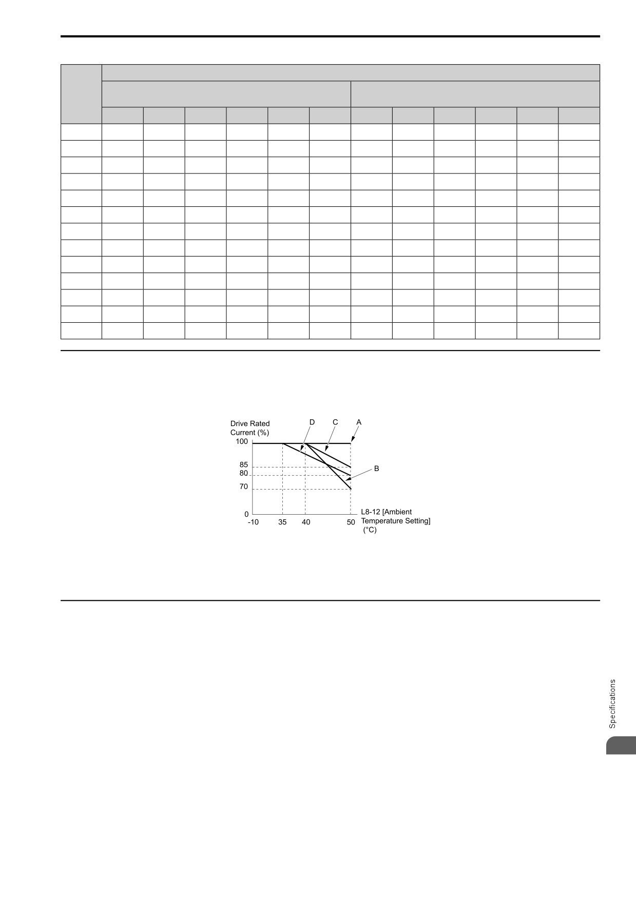
Table 10.17 AOLV/PM Carrier Frequency and Rated Current Derating (Three-Phase 400 V)
Rated Current (A)
Heavy Duty Rating (HD)
Normal Duty Rating (ND)
Model
[C6-01 = 0]
[C6-01 = 1]
2 kHz
4 kHz
6 kHz
8 kHz
10 kHz
12 kHz
2 kHz
4 kHz
6 kHz
8 kHz
10 kHz
12 kHz
4001
1.2
1.2
1.1
0.9
0.7
0.5
1.2
1.2
1.1
0.9
0.7
0.5
4002
1.8
1.8
1.7
1.4
1.1
0.8
2.1
2.0
1.7
1.4
1.1
0.8
4004
3.4
3.4
3.2
2.6
2.0
1.5
4.1
3.8
3.2
2.6
2.0
1.5
4005
4.8
4.8
4.5
3.7
2.9
2.1
5.4
5.3
4.5
3.7
2.9
2.1
4007
5.5
5.5
5.2
4.2
3.3
2.4
7.1
6.2
5.2
4.3
3.3
2.4
4009
7.3
7.3
6.9
5.6
4.4
3.1
8.9
8.1
6.9
5.6
4.4
3.1
4012
9.2
9.2
8.7
7.1
5.5
3.9
11.9
10.3
8.7
7.1
5.5
3.9
4018
14.8
14.8
14.0
11.4
8.9
6.3
17.8
16.4
15.2
11.4
8.8
6.3
4023
18.0
18.0
17.0
13.9
10.8
7.7
23.4
20.3
17.1
14.0
10.8
7.7
4031
24.0
24.0
22.6
18.5
14.4
10.3
31.0
26.9
22.7
18.6
14.4
10.3
4038
31.0
31.0
29.2
23.9
18.6
13.3
38.0
34.5
29.2
23.9
18.6
13.3
4044
39.0
39.0
36.8
30.1
23.4
16.7
44.0
43.5
36.8
30.1
23.4
16.7
4060
45.0
45.0
42.4
34.7
27.0
19.3
60.0
51.8
43.5
35.3
27.0
18.8
◆ Derating Depending on Ambient Temperature
When you install drives in a place where ambient temperatures are higher than the rated conditions or install
drives side-by-side in the enclosure panel, set L8-12 [Ambient Temperature Setting] and L8-35 [Installation
Selection]. Derate the output current as specified in Figure 10.1.
A - L8-35 = 0 [IP00/IP20/Open-Chassis]
C - L8-35 = 2 [ULType 1]
B - L8-35 = 1 [Side-by-Side Mounting]
D - L8-35 = 3 [Ext. Heatsink]
Figure 10.1 Derating Depending on Drive Installation Method
◆ Altitude Derating
Install the drive in a location that has an altitude of 1000 m (3281 ft) or lower.
Derate the output current by 1% for each 100 m (328 ft) to install the drive in altitudes between 1000 to 4000 m
(3281 to 13123 ft).
It is not necessary to derate the rated voltage in these conditions:
• Installing the drive at 2000 m (6562 ft) or lower
• Installing the drive between 2000 to 4000 m (6562 to 13123 ft) and grounding the neutral point on the power
supply.
If you do not ground the drive with a neutral network, contact the manufacturer or your nearest sales
representative.
10
303
10.8 Drive Models and Drive Watt Loss
10.8
Drive Models and Drive Watt Loss
◆ Drive Watt Loss
■ Three-Phase 200 V Class
Table 10.18 Drive Watt Loss (HD, Fc = 2 kHz)
Rated output current
Carrier Frequency
Interior Unit Loss
Cooling Fin Loss
Total Loss
Model
A
kHz
W
W
W
2001
0.8
2
7
4
11
2002
1.6
2
8
7
15
2004
3.0
2
12
13
25
2006
5.0
2
20
22
42
2008
??
2
??
??
??
2010
8.0
2
18
37
55
2012
11.0
2
24
49
73
2018
??
2
??
??
??
2021
17.6
2
37
83
120
2030
25.0
2
46
163
209
2042
33.0
2
56
200
256
2056
47.0
2
78
269
347
2070
60.0
2
109
411
520
2082
75.0
2
133
439
572
Table 10.19 Drive Watt Loss (HD, Fc = Default Setting)
Rated output current
Carrier Frequency
Interior Unit Loss
Cooling Fin Loss
Total Loss
Model
A
kHz
W
W
W
2001
1.2
10
7
5
12
2002
1.9
10
8
8
16
2004
3.5
10
13
16
29
2006
6
10
21
27
48
2008
??
8
??
??
??
2010
9.6
8
19
43
62
2012
12.2
8
25
56
81
2018
??
8
??
??
??
2021
21
8
41
108
149
2030
30
8
50
187
237
2042
42
8
61
232
293
2056
56
8
86
318
404
2070
70
8
120
473
593
2082
82
8
149
525
674
■ Single-Phase 200 V Class
Table 10.20 Drive Watt Loss (HD, Fc = 2 kHz)
Rated output current
Carrier Frequency
Interior Unit Loss
Cooling Fin Loss
Total Loss
Model
A
kHz
W
W
W
B001
0.8
2
8
4
12
B002
1.6
2
12
7
19
B004
3
2
17
13
30
B006
5
2
20
23
43
304
10.8 Drive Models and Drive Watt Loss
Rated output current
Carrier Frequency
Interior Unit Loss
Cooling Fin Loss
Total Loss
Model
A
kHz
W
W
W
B010
8
2
34
37
71
B012
11
2
45
48
93
B018
17.6
2
50
72
122
Table 10.21 Drive Watt Loss (HD, Fc = Default Setting)
Rated output current
Carrier Frequency
Interior Unit Loss
Cooling Fin Loss
Total Loss
Model
A
kHz
W
W
W
B001
0.8
10
9
5
14
B002
1.6
10
12
9
21
B004
3
10
18
16
34
B006
5
10
21
28
49
B010
8
8
35
42
77
B012
11
8
46
55
101
B018
17.6
8
54
98
152
Table 10.22 Drive Watt Loss (ND)
Rated output current
Carrier Frequency
Interior Unit Loss
Cooling Fin Loss
Total Loss
Model
A
kHz
W
W
W
B001
1.2
2
9
6
15
B002
1.9
2
18
11
29
B004
3.5
2
19
17
36
B006
6.0
2
20
26
46
B010
9.6
2
44
50
94
B012
12.2
2
56
60
116
B018
N/A
2
50
92
142
■ Three-Phase 400 V Class
Table 10.23 Drive Watt Loss (HD, Fc = 2 kHz)
Rated output current
Carrier Frequency
Interior Unit Loss
Cooling Fin Loss
Total Loss
Model
A
kHz
W
W
W
4001
1.2
2
9
7
16
4002
1.8
2
11
10
21
4004
3.4
2
15
21
36
4005
4.8
2
17
29
46
4007
5.6
2
18
33
51
4009
7.3
2
24
45
69
4012
9.2
2
29
60
89
4018
14.8
2
52
126
178
4023
18
2
57
152
209
4031
24
2
73
191
264
4038
31
2
89
256
345
4044
39
2
119
338
457
4060
45
2
128
328
456
10
Table 10.24 Drive Watt Loss (HD, Fc = Default Setting)
Rated output current
Carrier Frequency
Interior Unit Loss
Cooling Fin Loss
Total Loss
Model
A
kHz
W
W
W
4001
1.2
8
10
11
21
4002
1.8
8
12
16
28
4004
3.4
8
17
31
48
305
10.8
Drive Models and Drive Watt Loss
Rated output current
Carrier Frequency
Interior Unit Loss
Cooling Fin Loss
Total Loss
Model
A
kHz
W
W
W
4005
4.8
8
20
42
62
4007
5.6
8
20
49
69
4009
7.3
8
28
65
93
4012
9.2
8
34
85
119
4018
14.8
8
59
166
225
4023
18
8
65
200
265
4031
24
8
84
255
339
4038
31
8
103
338
441
4044
39
8
137
442
579
4060
45
8
149
446
595
Table 10.25 Drive Watt Loss (ND)
Rated output current
Carrier Frequency
Interior Unit Loss
Cooling Fin Loss
Total Loss
Model
A
kHz
W
W
W
4001
1.2
2
9
7
16
4002
2.1
2
14
12
26
4004
4.1
2
16
24
40
4005
5.4
2
18
32
50
4007
7.1
2
23
44
67
4009
8.9
2
33
58
91
4012
11.9
2
41
83
124
4018
17.5
2
56
155
211
4023
23.4
2
94
236
330
4031
31
2
109
284
393
4038
38
2
119
341
460
4044
44
2
151
417
568
4060
60
2
200
490
690
306
10.9 Drive Exterior and Mounting Dimensions
10.9
Drive Exterior and Mounting Dimensions
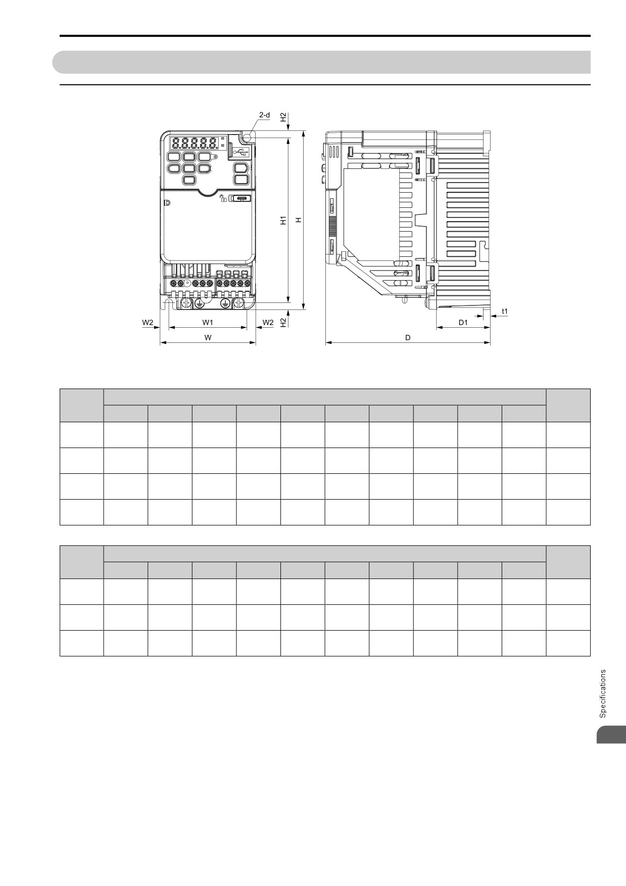
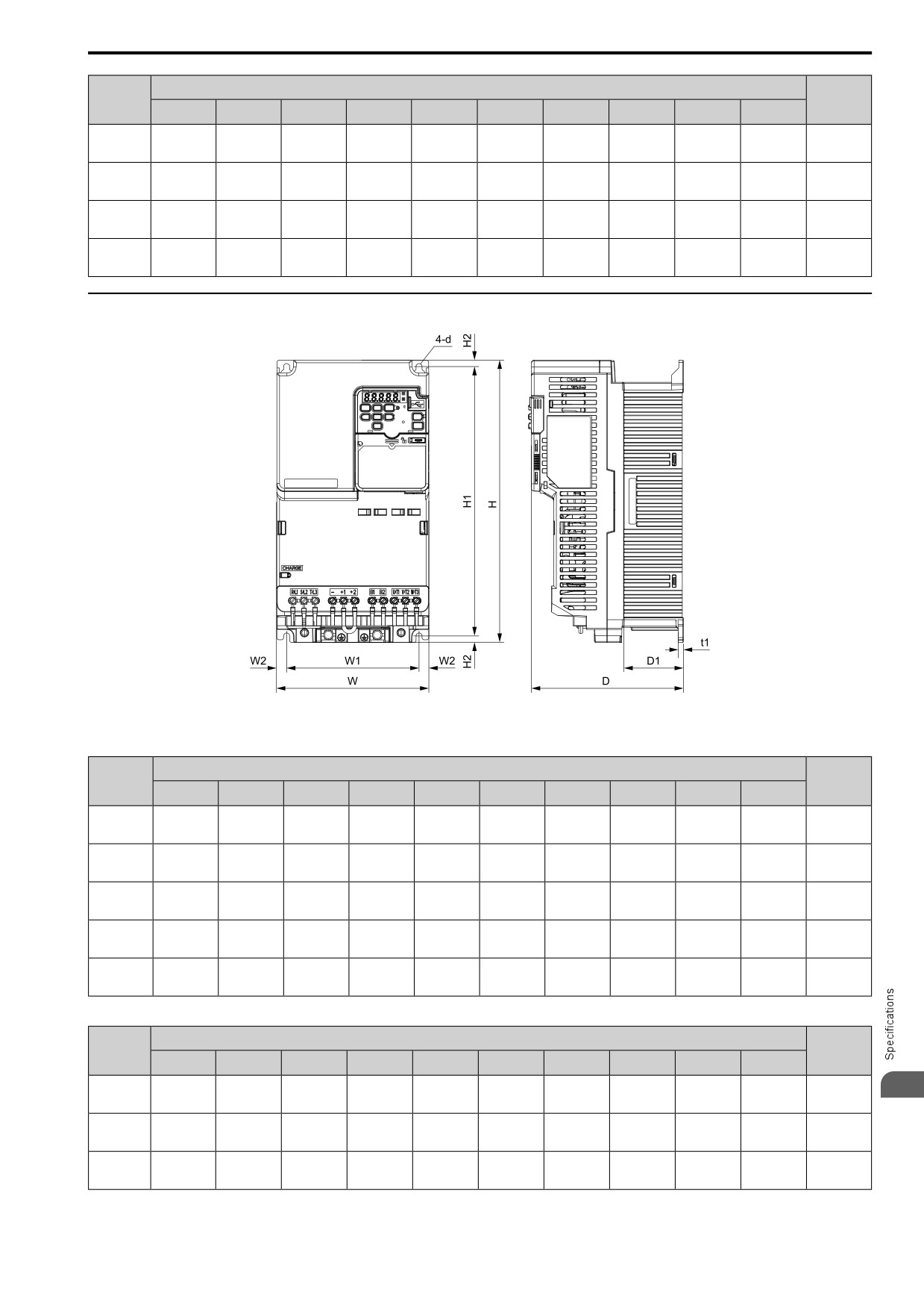
◆ IP20/UL Open Type (Models 2001 to 2006, B001 to B004)
Figure 10.2 Exterior and Mounting Dimensions
Table 10.26 Three-Phase 200 V Class (IP20/UL Open Type, with Built-in EMC Filter)
Dimensions mm (in)
Est.
Model
Weight
W
H
D
W1
W2
H1
H2
D1
t1
d
kg (lb)
68
128
116
56
6
118
5
6.5
3
0.6
2001
M5
(2.68)
(5.04)
(4.57)
(2.20)
(0.24)
(4.65)
(0.20)
(0.26)
(0.12)
(1.3)
68
128
116
56
6
118
5
6.5
3
0.6
2002
M5
(2.68)
(5.04)
(4.57)
(2.20)
(0.24)
(4.65)
(0.20)
(0.26)
(0.12)
(1.3)
68
128
148
56
6
118
5
38.5
5
0.9
2004
M5
(2.68)
(5.04)
(5.83)
(2.20)
(0.24)
(4.65)
(0.20)
(1.52)
(0.20)
(2.0)
68
128
168
56
6
118
5
58.5
5
1.1
2006
M5
(2.68)
(5.04)
(6.61)
(2.20)
(0.24)
(4.65)
(0.20)
(2.30)
(0.20)
(2.4)
Table 10.27 Single-Phase 200 V Class (IP20/UL Open Type, with Built-in EMC Filter)
Dimensions mm (in)
Est.
Model
Weight
W
H
D
W1
W2
H1
H2
D1
t1
d
kg (lb)
68
128
116
56
6
118
5
6.5
3
0.7
B001
M5
(2.68)
(5.04)
(4.57)
(2.20)
(0.24)
(4.65)
(0.20)
(0.26)
(0.12)
(1.6)
68
128
116
56
6
118
5
6.5
3
0.7
B002
M5
(2.68)
(5.04)
(4.57)
(2.20)
(0.24)
(4.65)
(0.20)
(0.26)
(0.12)
(1.6)
68
128
158
56
6
118
5
38.5
5
1.0
B004
M5
(2.68)
(5.04)
(6.22)
(2.20)
(0.24)
(4.65)
(0.20)
(1.52)
(0.20)
(2.2)
10
307
10.9 Drive Exterior and Mounting Dimensions
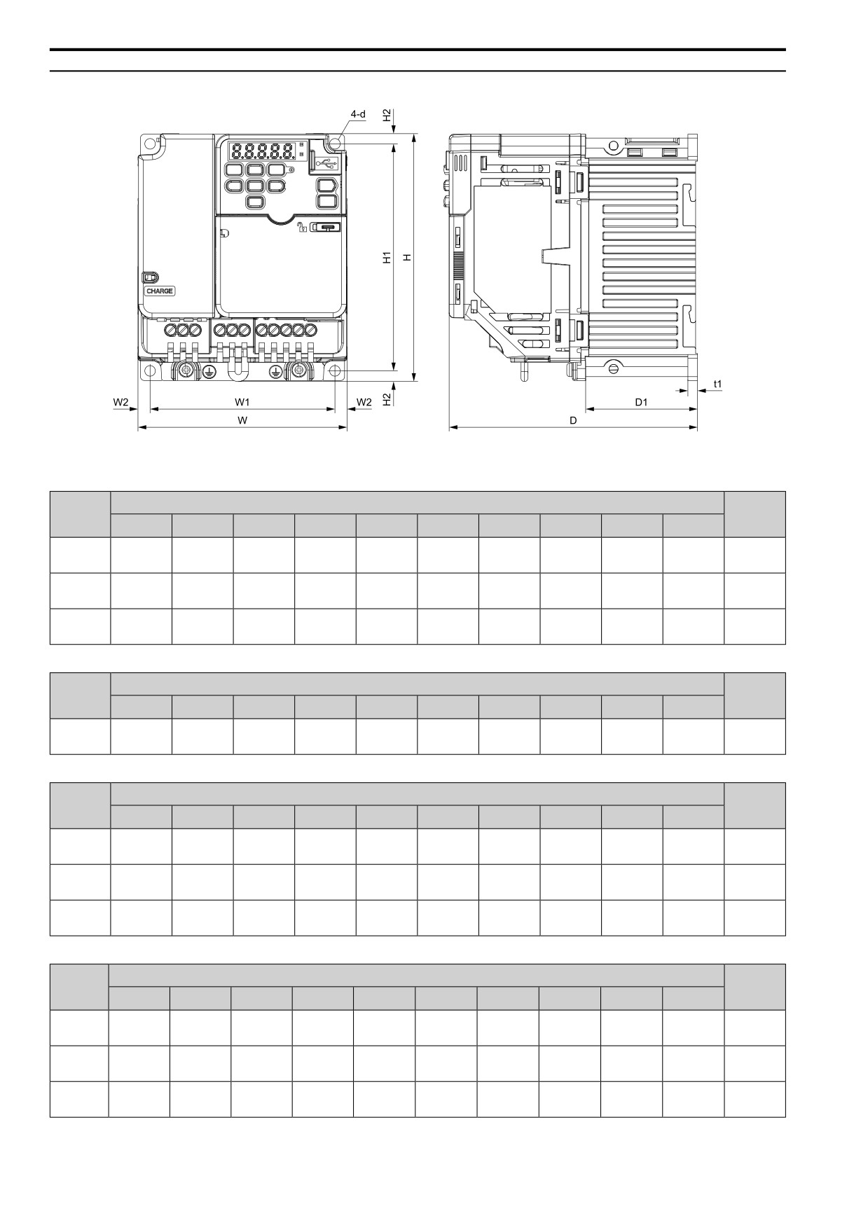
◆ IP20/UL Open Type (Models 2010 to 2021, B006 to B018, 4001 to 4012)
Figure 10.3 Exterior and Mounting Dimensions
Table 10.28 Three-Phase 200 V Class (IP20/UL Open Type, with Built-in EMC Filter)
Dimensions mm (in)
Est.
Model
Weight
W
H
D
W1
W2
H1
H2
D1
t1
d
kg (lb)
108
128
174
96
6
118
5
56.5
5
1.6
2010
M5
(4.25)
(5.04)
(6.85)
(3.78)
(0.24)
(4.65)
(0.20)
(2.22)
(0.20)
(3.5)
108
128
182.5
96
6
118
5
56.5
5
1.6
2012
M5
(4.25)
(5.04)
(7.19)
(3.78)
(0.24)
(4.65)
(0.20)
(2.22)
(0.20)
(3.5)
140
128
193
128
6
118
5
65
5
2.4
2021
M5
(5.51)
(5.04)
(7.60)
(5.04)
(0.24)
(4.65)
(0.20)
(2.56)
(0.20)
(5.3)
Table 10.29 Single-Phase 200 V Class (IP20/UL Open Type, without Built-in EMC Filter)
Dimensions mm (in)
Est.
Model
Weight
W
H
D
W1
W2
H1
H2
D1
t1
d
kg (lb)
170
128
180
158
6
118
5
65
5
2.9
B018
M5
(6.69)
(5.04)
(7.09)
(6.22)
(0.24)
(4.65)
(0.20)
(2.56)
(0.20)
(6.4)
Table 10.30 Single-Phase 200 V Class (IP20/UL Open Type, with Built-in EMC Filter)
Dimensions mm (in)
Est.
Model
Weight
W
H
D
W1
W2
H1
H2
D1
t1
d
kg (lb)
108
128
182.5
96
6
118
5
56.5
5
1.8
B006
M5
(4.25)
(5.04)
(7.19)
(3.78)
(0.24)
(4.65)
(0.20)
(2.22)
(0.20)
(4.0)
108
128
199
96
6
118
5
56.5
5
1.8
B010
M5
(4.25)
(5.04)
(7.83)
(3.78)
(0.24)
(4.65)
(0.20)
(2.22)
(0.20)
(4.0)
140
128
203
128
6
118
5
65
5
2.7
B012
M5
(5.51)
(5.04)
(7.99)
(5.04)
(0.24)
(4.65)
(0.20)
(2.56)
(0.20)
(6.0)
Table 10.31 Three-Phase 400 V Class (IP20/UL Open Type, with Built-in EMC Filter)
Dimensions mm (in)
Est.
Model
Weight
W
H
D
W1
W2
H1
H2
D1
t1
d
kg (lb)
108
128
126
96
6
118
5
8.5
5
1.4
4001
M5
(4.25)
(5.04)
(4.96)
(3.78)
(0.24)
(4.65)
(0.20)
(0.33)
(0.20)
(3.1)
108
128
144
96
6
118
5
26.5
5
1.5
4002
M5
(4.25)
(5.04)
(5.67)
(3.78)
(0.24)
(4.65)
(0.20)
(1.04)
(0.20)
(3.3)
108
128
182.5
96
6
118
5
56.5
5
1.9
4004
M5
(4.25)
(5.04)
(7.19)
(3.78)
(0.24)
(4.65)
(0.20)
(2.22)
(0.20)
(4.2)
308
10.9 Drive Exterior and Mounting Dimensions
Dimensions mm (in)
Est.
Model
Weight
W
H
D
W1
W2
H1
H2
D1
t1
d
kg (lb)
108
128
199
96
6
118
5
56.5
5
1.9
4005
M5
(4.25)
(5.04)
(7.83)
(3.78)
(0.24)
(4.65)
(0.20)
(2.22)
(0.20)
(4.2)
108
128
199
96
6
118
5
56.5
5
1.9
4007
M5
(4.25)
(5.04)
(7.83)
(3.78)
(0.24)
(4.65)
(0.20)
(2.22)
(0.20)
(4.2)
108
128
199
96
6
118
5
56.5
5
1.9
4009
M5
(4.25)
(5.04)
(7.83)
(3.78)
(0.24)
(4.65)
(0.20)
(2.22)
(0.20)
(4.2)
140
128
193
128
6
118
5
65
5
2.6
4012
M5
(5.51)
(5.04)
(7.60)
(5.04)
(0.24)
(4.65)
(0.20)
(2.56)
(0.20)
(5.7)
◆ IP20/UL Open Type (Models 2030 to 2082, 4018 to 4060)
Figure 10.4 Exterior and Mounting Dimensions
Table 10.32 Three-Phase 200 V Class (IP20/UL Open Type, with Built-in EMC Filter)
Dimensions mm (in)
Est.
Model
Weight
W
H
D
W1
W2
H1
H2
D1
t1
d
kg (lb)
140
260
196
122
9
248
6
55
5
3.9
2030
M5
(5.51)
(10.24)
(7.72)
(4.80)
(0.35)
(9.76)
(0.24)
(2.17)
(0.20)
(8.6)
140
260
196
122
9
248
6
55
5
4.1
2042
M5
(5.51)
(10.24)
(7.72)
(4.80)
(0.35)
(9.76)
(0.24)
(2.17)
(0.20)
(9.0)
180
300
196
160
10
284
8
55
5
6.0
2056
M5
(7.09)
(11.81)
(7.72)
(6.30)
(0.39)
(11.18)
(0.31)
(2.17)
(0.20)
(13.2)
220
350
216
192
14
336
7
78
5
8.5
2070
M6
(8.66)
(13.78)
(8.50)
(7.56)
(0.55)
(13.23)
(0.28)
(3.07)
(0.20)
(18.7)
220
350
216
192
14
336
7
78
5
9.0
2082
M6
(8.66)
(13.78)
(8.50)
(7.56)
(0.55)
(13.23)
(0.28)
(3.07)
(0.20)
(19.9)
Table 10.33 Three-Phase 400 V Class (IP20/UL Open Type, with Built-in EMC Filter)
Dimensions mm (in)
Est.
Model
Weight
W
H
D
W1
W2
H1
H2
D1
t1
d
kg (lb)
140
260
196
122
9
248
6
55
5
3.9
10
4018
M5
(5.51)
(10.24)
(7.72)
(4.80)
(0.35)
(9.76)
(0.24)
(2.17)
(0.20)
(8.6)
140
260
196
122
9
248
6
55
5
3.9
4023
M5
(5.51)
(10.24)
(7.72)
(4.80)
(0.35)
(9.76)
(0.24)
(2.17)
(0.20)
(8.6)
180
300
196
160
10
284
8
55
5
5.5
4031
M5
(7.09)
(11.81)
(7.72)
(6.30)
(0.39)
(11.18)
(0.31)
(2.17)
(0.20)
(12.1)
309
10.9 Drive Exterior and Mounting Dimensions
Dimensions mm (in)
Est.
Model
Weight
W
H
D
W1
W2
H1
H2
D1
t1
d
kg (lb)
180
300
196
160
10
284
8
55
5
5.5
4038
M5
(7.09)
(11.81)
(7.72)
(6.30)
(0.39)
(11.18)
(0.31)
(2.17)
(0.20)
(12.1)
190
350
251
160
15
336
7
94
5
8.0
4044
M6
(7.48)
(13.78)
(9.88)
(6.30)
(0.59)
(13.23)
(0.28)
(3.70)
(0.20)
(17.6)
190
350
251
160
15
336
7
94
5
8.5
4060
M6
(7.48)
(13.78)
(9.88)
(6.30)
(0.59)
(13.23)
(0.28)
(3.70)
(0.20)
(18.7)
310
10.10 Peripheral Devices and Options
10.10
Peripheral Devices and Options
These tables show the available peripheral devices and options for the drive. Contact the manufacturer or your
nearest sales representative to make an order.
• Selection: Refer to the drive catalog for information about available products.
• Installation and wiring: Refer to the instruction manual for each option.
Table 10.34 Main Circuit Options
Name
Model
Intended Use
To improve the drive input power factor.
• To prevent damage to the drive when the power supply capacity is large. You must only use this option
AC reactor
LR3 series and ALR3 series
when the power supply capacity is more than 600 kVA.
• To decrease harmonic current.
• To improve the power supply total power factor.
To decrease the regenerative energy of the motor and decrease the deceleration time (duty cycle of 3%
Braking Resistor
ERF-150WJ Series
ED). You must also use the installation attachment.
To prevent short circuit damage to the power supply system, provide overload protection for wiring,
prevent electrical shock, and provide ground fault protection against earth leakage fires.
Note:
Residual Current Monitoring/
NV and NS series
• You can use a molded-case circuit breaker as a replacement for an RCM/RCD that is upstream in the
Detection (RCM/RCD)
power supply system.
• When you use a high frequency RCM/RCD at the power input side of the drive, make sure that each
drive has a minimum cumulative sensitivity amperage of 30 mA.
Molded-Case Circuit Breaker
NF series
To prevent short circuit damage to the power supply system and provide overload protection for wiring.
(MCCB)
Input Side Magnetic Contactor
To prevent burn damage when connecting a braking resistor. This option fully opens the circuit between
SC series
(MC)
the power supply and drive.
Table 10.35 Attachments
Name
Model
Intended Use
Heatsink External Mounting Kit
ZPSA-GA50Vx-x
Use this option to install the heatsink outside of the control panel.
ZPZ-GA50Vx
To use a DIN rail to install the drive.
DIN Rail Attachment
EZZ08122D
Communication Option Case
JOHB-Q2V
To install a communication option on a drive.
Table 10.36 Engineering Tools
Name
Model
Intended Use
Q2edit
-
To use a PC to program drives and manage parameters.
Q2dev
-
To use a PC to do advanced drive programming.
Table 10.37 Communication Options
Name
Model
Intended Use
Document No.
This option uses the host controller over EtherNet/IP communication to:
• Operate and stop the drive
TOBPC73060092
EtherNet/IP
SI-EN3
• Set and view parameters
SIJPC73060092
• Monitor output frequency, output current, and other statuses
This option uses the host controller over PROFINET communication to:
• Operate and stop the drive
TOBPC73060089
PROFINET
SI-EP3
• Set and view parameters
SIJPC73060089
• Monitor output frequency, output current, and other statuses
This option uses the host controller over EtherCAT communication to:
• Operate and stop the drive
Contact the manufacturer or your nearest
EtherCAT
SI-ES3
• Set and view parameters
sales representative for more information.
• Monitor output frequency, output current, and other statuses
This option uses the host controller over Powerlink communication to:
• Operate and stop the drive
Contact the manufacturer or your nearest
Powerlink
SI-EL3
• Set and view parameters
sales representative for more information.
10
• Monitor output frequency, output current, and other statuses
311
10.10 Peripheral Devices and Options
312
11
Parameter List
11.1
How to Read the Parameter List
314
11.2
Parameter Groups
315
11.3
A: INITIALIZATION
316
11.4
b: APPLICATION
318
11.5
C: TUNING
327
11.6
d: REFERENCE
331
11.7
E: MOTOR
335
11.8
F: OPTIONS
340
11.9
H: TERMINALS
348
11.10
L: PROTECTION
365
11.11
n: SPECIAL
375
11.12
o: KEYPAD
381
11.13
q: Q2PACK PARAMETERS
387
11.14
r: Q2PACK JOINTS
388
11.15
T: AUTOTUNING
389
11.16
U: MONITORS
392
11.17
Parameters that Change from the Default Settings with A1-02 [Control
Method]
403
11.18
Parameters that Change from the Default Settings with E3-01 [M2
Control Method Selection]
407
11.19
Parameters Changed by E1-03 [V/f Pattern Selection]
408
11.20
Defaults by Drive Model and Duty Rating ND/HD
409
11.21
Parameters Changed by PM Motor Code Selection
421
313
11.1 How to Read the Parameter List
11.1
How to Read the Parameter List
◆ Icons and Terms that Identify Parameters and Control Modes
Icon
Description
V/f
The parameter is available when operating the drive with V/f Control.
OLV
The parameter is available when operating the drive with OLVector.
OLV/PM
The parameter is available when operating the drive with PM OLVector.
AOLV/PM
The parameter is available when operating the drive with PM AOLVector.
EZOLV
The parameter is available when operating the drive with EZ Vector.
Hex.
Hexadecimal numbers that represent Modbus addresses to change parameters over network communication.
RUN
The parameter can be changed settings during run.
Expert
The parameter that is available in Expert Mode only. *1
*1
Set A1-01 = 3 [Access Level = Expert Parameters] to display and set Expert Mode parameters on the keypad.
Note:
Gray icons identify parameters that are not available in the specified control method.
314
11.2 Parameter Groups
11.2
Parameter Groups
Represents the type of product parameters.
Parameter
Name
Parameter
Name
A: INITIALIZATION
H7
H7: VIRTUAL INPUT OUTPUT
A1
A1: INITIALIZATION
L: PROTECTION
A2
A2: MANUAL SELECTION
L1
L1: MOTOR PROTECTION
b: APPLICATION
L2
L2: POWER LOSS RIDE THROUGH
b1
b1: OPERATION MODE SELECT
L3
L3: STALL PREVENTION
b2
b2: DC INJ / SHORT CKT BRAKE
L4
L4: SPEED DETECTION
b3
b3: SPEED SEARCH
L5
L5: FAULT RESTART
b4
b4: TIMER
L6
L6: TORQUE DETECTION
b5
b5: PID CONTROL
L7
L7: TORQUE LIMIT
b6
b6: DWELL FUNCTION
L8
L8: DRIVE PROTECTION
b8
b8: ENERGY SAVING
n: SPECIAL
C: TUNING
n1
n1: HUNTING PREVENTION
C1
C1: ACCEL / DECEL
n2
n2: AFR - AUTO FREQ REGULATION
C2
C2: JERK CONTROL
n3
n3: HIGHSLIP/OVEREXCITATION BRAKE
C3
C3: SLIP COMPENSATION
n5
n5: FEED FORWARD CONTROL
C4
C4: TORQUE COMPENSATION
n6
n6: ONLINE TUNING
C5
C5: ASR - SPEED REGULATION
n7
n7: SIMPLE VECTOR TUNING
C6
C6: DUTY AND CARRIER
n8
n8: PM MOTOR CONTROL TUNING
d: REFERENCE
nA
nA: PM MOTOR CONTROL TUNING
d1
d1: FREQUENCY REFERENCE
o: KEYPAD
d2
d2: REFERENCE LIMITS
o1
o1: KEYPAD DISPLAY
d3
d3: JUMP FREQUENCY
o2
o2: KEYPAD OPERATION
d4
d4: FREQUENCY UP/DOWN
o3
o3: COPY FUNCTION
d6
d6: FIELD WEAKENING / FORCING
o4
o4: MAINTENANCE MONITORS
d7
d7: OFFSET FREQUENCY
o5
o5: DATA LOGGER
E: MOTOR
q: Q2PACK PARAMETERS
E1
E1: V/F PARAMETER MOTOR 1
q
q1-01 to q8-40: Q2pack Parameters
E2
E2: MOTOR 1 PARAMETERS
r: Q2PACK JOINTS
E3
E3: V/F PARAMETER MOTOR 2
r
r1: Q2PACK JOINTS
E4
E4: MOTOR 2 PARAMETERS
T: AUTOTUNING
E5
E5: PM MOTOR SETTINGS
T0
T0: TUNE MODE
E9
E9: SIMPLE VECTOR SETTINGS
T1
T1: INDUCTION MOTOR
F: OPTIONS
T2
T2: PM MOTOR
F1
F1: ENCODER
T3
T3: ASR
F6
F6: COMMUNICATIONS
T4
T4: SIMPLE VECTOR
F7
F7: ETHERNET
U1
U1: STATUS
H: TERMINALS
U2
U2: FAULT
H1
H1: DIGITAL INPUTS
U3
U3: FAULT HISTORY
H2
H2: DIGITAL OUTPUTS
U4
U4: MAINTENANCE
11
H3
H3: ANALOG INPUTS
U5
U5: PID
H4
H4: ANALOG OUTPUTS
U6
U6: ADVANCED
H5
H5: MODBUS PORTS
U8
U8: Q2PACK MONITORS
H6
H6: PULSE INPUT OUTPUT
315