Q2V Driving Quality. Technical Manual (Item code: Q2V-Axxxx-xxx, 2020) - page 7
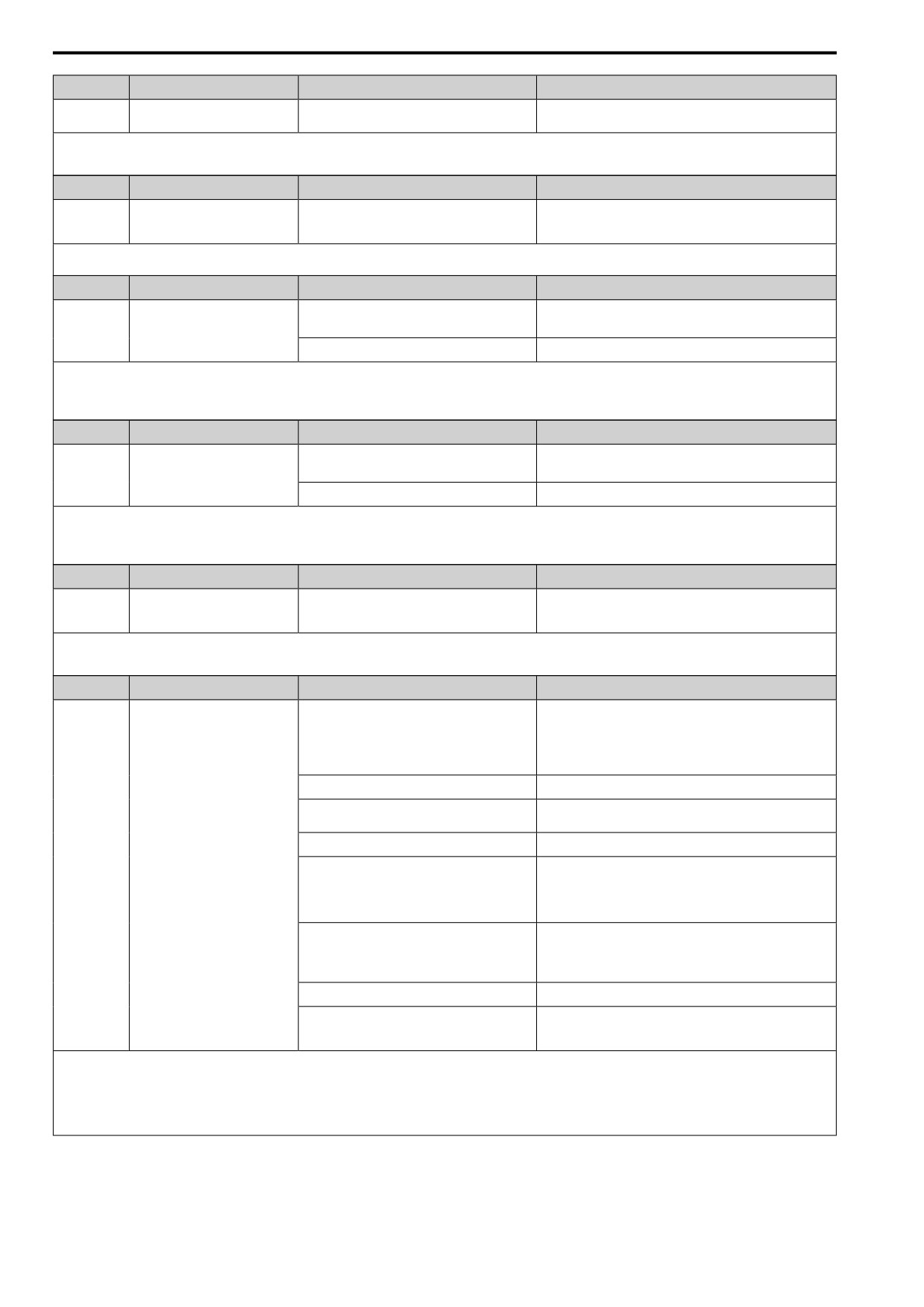
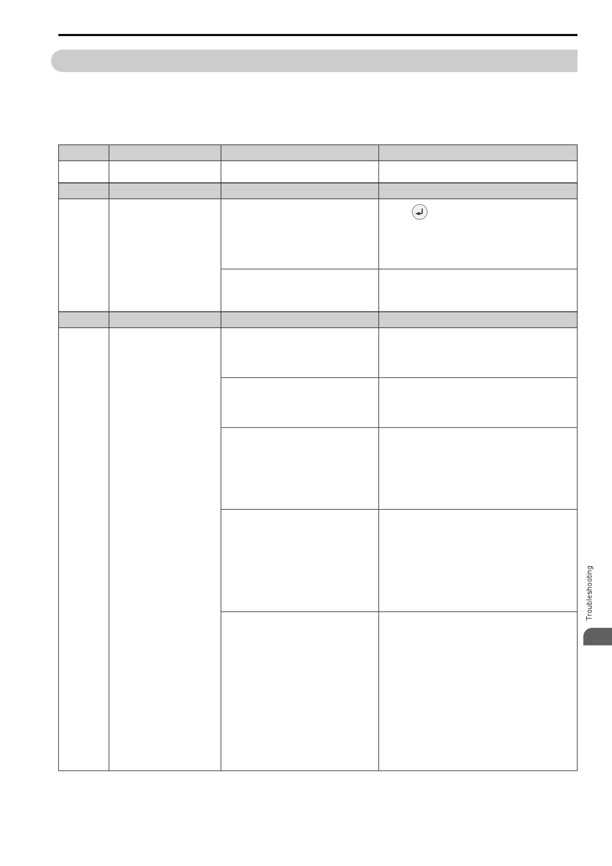
7.5 Minor Faults/Alarms
7.5
Minor Faults/Alarms
This section gives information about the causes and possible solutions when a minor fault or alarm occurs. Use
the information in this table to remove the cause of the minor fault or alarm.
Code
Name
Causes
Possible Solutions
AEr
Station Address Setting Error
The node address for the communication option is
• For CC-Link communication, set F6-10 [CCLink Node
not in the permitted setting range.
Address] correctly.
• For MECHATROLINK communication, set F6-20 [MLII
Address] correctly.
• For CANopen communication, set F6-35 [CANopen Address]
correctly.
Note:
If the drive detects this error, the terminal set to H2-01 to H2-03 = 4 [MFDO Function Select = Alarm] will activate.
Code
Name
Causes
Possible Solutions
bAT
Keypad Battery Low Voltage
The keypad battery voltage is low.
Replace the keypad battery.
Note:
• If the drive detects this error, the terminal set to H2-01 to H2-03 = 4 [MFDO Function Selection = Alarm] will activate.
• Parameter o4-24 [bAT Detection Selection] enables and disables bAT detection.
Code
Name
Causes
Possible Solutions
bb
Baseblock
An external baseblock command was entered
Examine the external sequence and timing of the baseblock
through MFDI terminal DI1 to DI7, and the drive
command input.
output stopped as shown by an external baseblock
command.
Note:
The drive will not output a minor fault signal for this alarm.
Code
Name
Causes
Possible Solutions
bCE
Bluetooth Communication Error
The smartphone or tablet with Q2dev Mobile
Use the smartphone or tablet 10 m (32.8 ft) or nearer to the
installed is too far from the keypad.
keypad.
Note:
bCE can occur when the smartphone or tablet is 10 m or
nearer to the keypad depending on the specifications of the
smartphone or tablet.
Radio waves from a different device are causing
Make sure that no device around the keypad uses the same radio
interference with the communication between the
bandwidth (2400 MHz to 2480 MHz), and prevent radio
smartphone or tablet and keypad.
interference.
Note:
• The drive detects this error when you operate the drive with a smartphone or tablet with a Bluetooth LCD Keypad.
• If the drive detects this error, the terminal assigned to H2-01 to H2-03 = 4 [MFDO Function Select = Alarm] will activate.
• Parameter o2-27 [BLE Disconn.Selection@BLE Ctrl] enables and disables bCE detection.
Code
Name
Causes
Possible Solutions
boL
Braking Transistor Overload
The duty cycle of the braking transistor is high (the
• Install a regenerative converter.
regeneration power or repetition frequency is high).
• Increase the deceleration time.
You enabled the protective function for the braking
Set L8-55 = 0 [DB IGBT Protection = Disable].
transistor when you have a regenerative converter.
The braking transistor in the drive is broken.
Replace the drive.
Note:
If the drive detects this error, the terminal set to H2-01 to H2-03 = 4 [MFDO Function Select = Alarm] will activate.
Code
Name
Causes
Possible Solutions
bUS
Option Communication Error
The communications cable wiring is incorrect.
Correct wiring errors.
There is a short-circuit in the communications cable
• Repair short circuits and connect cables.
or the communications cable is not connected.
• Replace the defective communications cable.
Electrical interference caused a communication data
• Examine the control circuit lines, main circuit lines, and
error.
ground wiring, and decrease the effects of electrical
interference.
• Make sure that a magnetic contactor is not the source of the
electrical interference, then use a Surge Protective Device if
necessary.
• Use only the recommended cables or other shielded line.
Ground the shield on the controller side or the drive input
power side.
• Separate the communication wiring from drive power lines,
and install a noise filter to the input side of the power supply
for communication.
• Decrease the effects of electrical interference from the
controller.
The option card is incorrectly installed to the drive.
Correctly install the option card to the drive.
238
7.5 Minor Faults/Alarms
Code
Name
Causes
Possible Solutions
The option card is damaged.
If the alarm continues and the wiring is correct, replace the option
card.
Note:
• The drive detects this error if the Run command or frequency reference is assigned to the option card.
• If the drive detects this error, the terminal set to H2-01 to H2-03 = 4 [MFDO Function Select = Alarm] will activate.
• If the drive detects this error, it will operate the motor as specified by the stopping method set in F6-01 [Comm.Error Selection].
Code
Name
Causes
Possible Solutions
CALL
Serial Comm Transmission Error
The communications cable wiring is incorrect.
Correct wiring errors.
There is a short-circuit in the communications cable
• Repair the short-circuited or disconnected portion of the cable.
or the communications cable is not connected.
• Replace the defective communications cable.
A programming error occurred on the controller
Examine communications at start-up and correct programming
side.
errors.
The communications circuitry is damaged.
• Do a self-diagnostics check.
• If the problem continues, replace the control board or the
drive. For information about replacing the control board,
contact the manufacturer or your nearest sales representative.
The termination resistor setting for Modbus
On the last drive in a Modbus network, set DIP switch S2 to the
communications is incorrect.
ON position to enable the termination resistor.
Note:
• The drive detects this error if it does not correctly receive control data from the controller when energizing the drive.
• If the drive detects this error, the terminal set to H2-01 to H2-03 = 4 [MFDO Function Select = Alarm] will activate.
Code
Name
Causes
Possible Solutions
CE
Modbus Communication Error
The communications cable wiring is incorrect.
Correct wiring errors.
There is a short-circuit in the communications cable
• Repair short circuits and connect cables.
or the communications cable is not connected.
• Replace the defective communications cable.
Electrical interference caused a communication data
• Examine the control circuit lines, main circuit lines, and
error.
ground wiring, and decrease the effects of electrical
interference.
• Make sure that a magnetic contactor is not the source of the
electrical interference, then use a Surge Protective Device if
necessary.
• Use only the recommended cables or other shielded line.
Ground the shield on the controller side or the drive input
power side.
• Separate the communication wiring from drive power lines,
and install a noise filter to the input side of the power supply
for communication.
• Decrease the effects of electrical interference from the
controller.
The communication protocol is not compatible.
• Examine the values set in H5-xx.
• Examine the settings on the controller side and correct the
difference in communication conditions.
The value set in H5-09 [Mbus CE Detect Time] is
• Change the controller software settings.
too small for the communications cycle.
• Increase the value set in H5-09.
The controller software or hardware is causing a
Examine the controller and remove the cause of the problem.
communication problem.
Note:
• The drive detects this error if it does not correctly receive control data for the CE detection time set to H5-09.
• If the drive detects this error, the terminal set to H2-01 to H2-03 = 4 [MFDO Function Select = Alarm] will activate.
• If the drive detects this error, it will operate the motor as specified by the stopping method set in H5-04 [Mbus Error Stop].
Code
Name
Causes
Possible Solutions
CP1
Comparator 1 Limit Error
The monitor value set in H2-20 [Compare1 Mon.
Examine the monitor value and remove the cause of the fault.
Selection] was in the range of H2-21 [Compare1
Low Limit] and H2-22 [Compare1 Up Limit].
7
Note:
• The drive detects this error when the terminal is assigned to H2-01 to H2-03 = 3C [MFDO Function Select = Comparator 1].
• If the drive detects this error, the terminal set to H2-01 to H2-03 = 4 [MFDO Function Select = Alarm] will activate.
• Parameter H2-33 [Compare1 Protection Selection] enables and disables CP1 detection.
Code
Name
Causes
Possible Solutions
CP2
Comparator 2 Limit Error
The monitor value set in H2-26 [Compare2 Mon.
Examine the monitor value and remove the cause of the fault.
Selection] was outside the range of H2-27
[Compare2 Low Limit] and H2-28 [Compare2 Up
Limit].
Note:
• The drive detects this error when the terminal is assigned to H2-01 to H2-03 = 3D [MFDO Function Select = Comparator 2].
• If the drive detects this error, the terminal set to H2-01 to H2-03 = 4 [MFDO Function Selection = Alarm] will activate.
• Parameter H2-35 [Compare2 Protection Selection] enables and disables CP2 detection.
Code
Name
Causes
Possible Solutions
CrST
Cannot Reset
The drive received a fault reset command when a
Turn off the Run command then de-energize and re-energize the
Run command was active.
drive.
239
7.5 Minor Faults/Alarms
Code
Name
Causes
Possible Solutions
CyC
MECHATROLINK
The communications cycle setting of the controller
Set the communications cycle of the controller in the permitted
CommCycleSettingErr
is not in the permitted range of the
range of the MECHATROLINK interface option.
MECHATROLINK interface option.
Note:
If the drive detects this error, the terminal set to H2-01 to H2-03 = 4 [MFDO Function Selection = Alarm] will activate.
Code
Name
Causes
Possible Solutions
CyPo
Cycle Power to Accept Changes
Although F6-15 = 1 [Comm. Option Parameters
Re-energize the drive to update the communication option
Reload = Reload Now], the drive does not update
parameters.
the communication option parameters.
Code
Name
Causes
Possible Solutions
dEv
Speed Deviation
The load is too large.
Decrease the load.
The acceleration/deceleration times are too short.
Increase the values set in C1-01 to C1-08 [Acceleration/
Deceleration Times].
The dEv detection level settings are incorrect.
Adjust F1-10 [Speed Dev Level] and F1-11 [Speed Dev Delay
Time].
The load is locked up.
Examine the machine.
The holding brake is stopping the motor.
Release the holding brake.
Note:
• The drive detects this error if the difference between the detected speed and the speed reference is more than the setting of F1-10 for longer than F1-11.
• If the drive detects this error, the terminal set to H2-01 to H2-03 = 4 [MFDO Function Select = Alarm] will activate.
• If the drive detects this error, it will operate the motor as specified by the stopping method set in F1-04 [Speed Dev Detection Select].
Code
Name
Causes
Possible Solutions
dnE
Drive Disabled
A terminal set for H1-xx = 1A [Drive Enable]
Examine the operation sequence.
turned OFF.
Note:
If the drive detects this error, the terminal set to H2-01 to H2-03 = 4 [MFDO Function Select = Alarm] will activate.
Code
Name
Causes
Possible Solutions
qAL2
Q2pack Alarm 2
There was an error in the Q2pack program.
Examine the Q2pack program and remove the cause of the fault.
This is not a drive fault.
Note:
If the drive detects this error, the terminal set to H2-01 to H2-03 = 4 [MFDO Function Select = Alarm] will activate.
Code
Name
Causes
Possible Solutions
qAL3
Q2pack Alarm 3
There was an error in the Q2pack program.
Examine the Q2pack program and remove the cause of the fault.
This is not a drive fault.
Note:
If the drive detects this error, the terminal set to H2-01 to H2-03 = 4 [MFDO Function Select = Alarm] will activate.
Code
Name
Causes
Possible Solutions
qAL1
Q2pack Alarm
There was an error in the Q2pack program.
Examine the Q2pack program and remove the cause of the fault.
This is not a drive fault.
Note:
If the drive detects this error, the terminal set to H2-01 to H2-03 = 4 [MFDO Function Select = Alarm] will activate.
Code
Name
Causes
Possible Solutions
E5
MECHATROLINK Watchdog
The drive detected a watchdog circuit exception
Examine the MECHATROLINK cable connection. If this error
Timer Err
while it received data from the controller.
occurs frequently, examine the wiring and decrease the effects of
electrical interference as specified by these manuals:
• MECHATROLINK-II Installation Guide (MECHATROLINK
Members Association, manual number MMATDEP011)
• MECHATROLINK-III Installation Manual
(MECHATROLINK Members Association, publication
number MMATDEP018)
Note:
• If the drive detects this error, the terminal set to H2-01 to H2-03 = 4 [MFDO Function Select = Alarm] will activate.
• If the drive detects this error, it will operate the motor as specified by the stopping method set in F6-25 [MLII Watchdog Error Sel].
Code
Name
Causes
Possible Solutions
EF
FWD/REV Run Command Input
A forward command and a reverse command were
Examine the forward and reverse command sequence and correct
Error
input at the same time for longer than 0.5 s.
the problem.
Note:
• If the drive detects EF, the motor will ramp to stop.
• If the drive detects this error, the terminal assigned to H2-01 to H2-03 = 4 [MFDO Function Select = Alarm] will be ON.
240
7.5 Minor Faults/Alarms
Code
Name
Causes
Possible Solutions
EF0
Option Card External Fault
The communication option card received an
1.
Find the device that caused the external fault and remove the
external fault from the controller.
caus.
2.
Clear the external fault input from the controller.
A programming error occurred on the controller
Examine the operation of the controller program.
side.
Note:
• The drive detects this error if the alarm function on the external device side is operating.
• If the drive detects this error, the terminal set to H2-01 to H2-03 = 4 [MFDO Function Select = Alarm] will activate.
• If the drive detects this error, it will operate the motor as specified by the stopping method set in F6-03 [Comm Ext Flt Select (EF0)].
Code
Name
Causes
Possible Solutions
EF1
External Fault (Terminal DI1)
MFDI terminal DI1 caused an external fault through
1.
Find the device that caused the external fault and remove the
an external device.
caus.
2.
Clear the external fault input in the MFDI.
The wiring is incorrect.
Correctly connect the signal line to MFDI terminal DI1.
External Fault [H1-01 = 2C to 2F] is set to MFDI
Correctly set the MFDI.
terminal DI1, but the terminal is not in use.
Note:
If the drive detects this error, the terminal set to H2-01 to H2-03 = 4 [MFDO Function Select = Alarm] will activate.
Code
Name
Causes
Possible Solutions
EF2
External Fault (Terminal DI2)
MFDI terminal DI2 caused an external fault through
1.
Find the device that caused the external fault and remove the
an external device.
caus.
2.
Clear the external fault input in the MFDI.
The wiring is incorrect.
Correctly connect the signal line to MFDI terminal DI2.
External Fault [H1-02 = 2C to 2F] is set to MFDI
Correctly set the MFDI.
terminal DI2, but the terminal is not in use.
Note:
If the drive detects this error, the terminal set to H2-01 to H2-03 = 4 [MFDO Function Selection = Alarm] will activate.
Code
Name
Causes
Possible Solutions
EF3
External Fault (Terminal DI3)
MFDI terminal DI3 caused an external fault through
1.
Find the device that caused the external fault and remove the
an external device.
caus.
2.
Clear the external fault input in the MFDI.
The wiring is incorrect.
Correctly connect the signal line to MFDI terminal DI3.
External Fault [H1-03 = 2C to 2F] is set to MFDI
Correctly set the MFDI.
terminal DI3, but the terminal is not in use.
Note:
If the drive detects this error, the terminal set to H2-01 to H2-03 = 4 [MFDO Function Selection = Alarm] will activate.
Code
Name
Causes
Possible Solutions
EF4
External Fault (Terminal DI4)
MFDI terminal DI4 caused an external fault through
1.
Find the device that caused the external fault and remove the
an external device.
caus.
2.
Clear the external fault input in the MFDI.
The wiring is incorrect.
Correctly connect the signal line to MFDI terminal DI4.
External Fault [H1-04 = 2C to 2F] is set to MFDI
Correctly set the MFDI.
terminal DI4, but the terminal is not in use.
Note:
If the drive detects this error, the terminal set to H2-01 to H2-03 = 4 [MFDO Function Selection = Alarm] will activate.
Code
Name
Causes
Possible Solutions
EF5
External Fault (Terminal DI5)
MFDI terminal DI5 caused an external fault through
1.
Find the device that caused the external fault and remove the
an external device.
caus.
2.
Clear the external fault input in the MFDI.
7
The wiring is incorrect.
Correctly connect the signal line to MFDI terminal DI5.
External Fault [H1-05 = 2C to 2F] is set to MFDI
Correctly set the MFDI.
terminal DI5, but the terminal is not in use.
Note:
If the drive detects this error, the terminal set to H2-01 to H2-03 = 4 [MFDO Function Selection = Alarm] will activate.
Code
Name
Causes
Possible Solutions
EF6
External Fault (Terminal DI6)
MFDI terminal DI6 caused an external fault through
1.
Find the device that caused the external fault and remove the
an external device.
caus.
2.
Clear the external fault input in the MFDI.
The wiring is incorrect.
Correctly connect the signal line to MFDI terminal DI6.
External Fault [H1-06 = 2C to 2F] is set to MFDI
Correctly set the MFDI.
terminal DI6, but the terminal is not in use.
Note:
If the drive detects this error, the terminal set to H2-01 to H2-03 = 4 [MFDO Function Selection = Alarm] will activate.
241
7.5 Minor Faults/Alarms
Code
Name
Causes
Possible Solutions
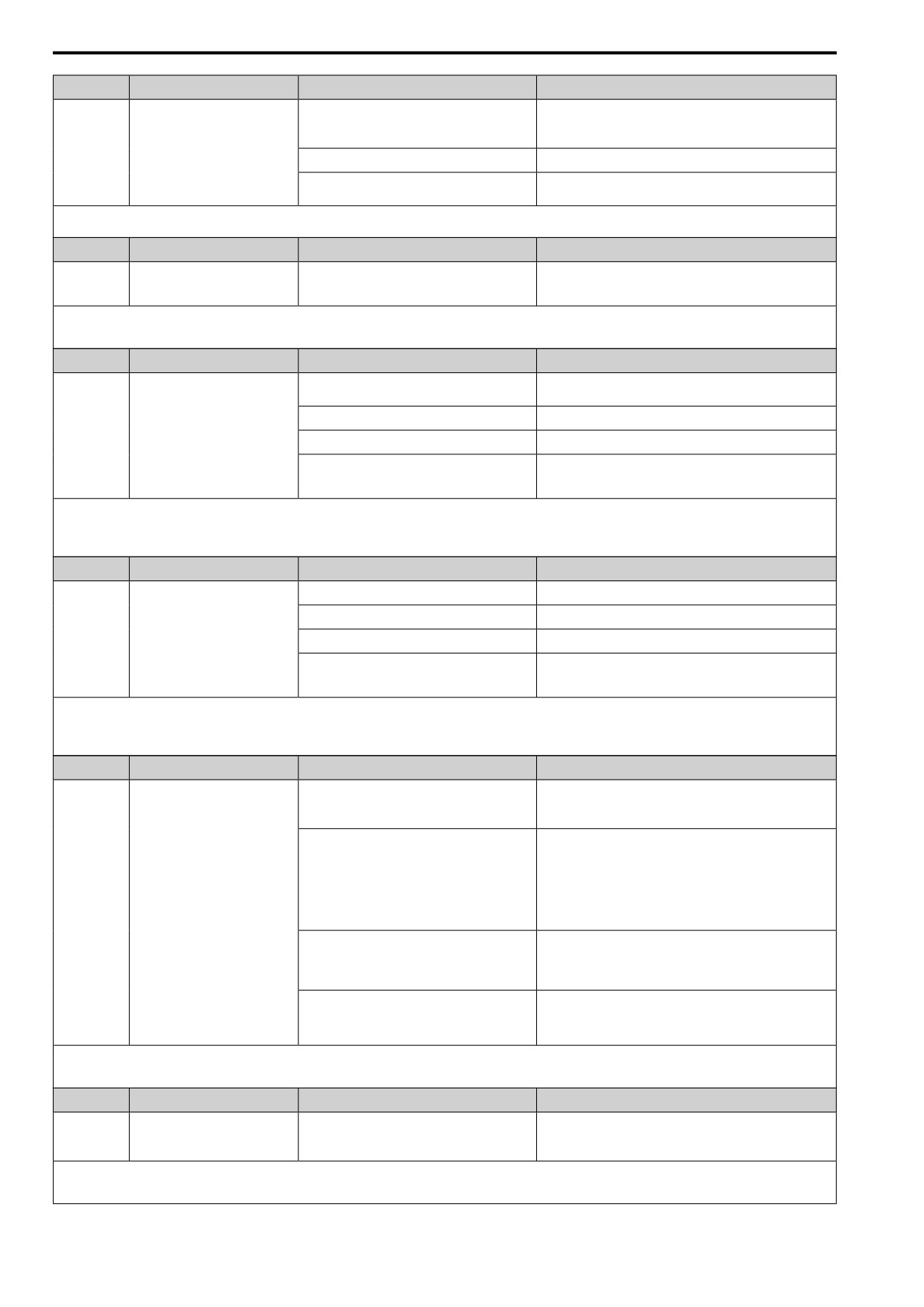
EF7
External Fault (Terminal DI7)
MFDI terminal DI7 caused an external fault through
1.
Find the device that caused the external fault and remove the
an external device.
caus.
2.
Clear the external fault input in the MFDI.
The wiring is incorrect.
Correctly connect the signal line to MFDI terminal DI7.
External Fault [H1-07 = 2C to 2F] is set to MFDI
Correctly set the MFDI.
terminal DI7, but the terminal is not in use.
Note:
If the drive detects this error, the terminal set to H2-01 to H2-03 = 4 [MFDO Function Selection = Alarm] will activate.
Code
Name
Causes
Possible Solutions
EP24v
External Power 24V Supply
The voltage of the main circuit power supply
• Examine the main circuit power supply.
decreased, and the 24 V power supply is supplying
• Turn ON the main circuit power supply to run the drive.
power to the drive.
Note:
• Set o2-26 [Ext24V Mode Warning Display] to enable or disable EP24v detection.
• The drive will not output an alarm signal for this alarm.
Code
Name
Causes
Possible Solutions
FbH
Excessive PID Feedback
The FbH detection level is set incorrectly.
Adjust b5-36 [PID HiHi Limit Level] and b5-37 [PID HiHi
Time].
There is a problem with the PID feedback wiring.
Correct errors with the PID control wiring.
The feedback sensor is not operating correctly.
Examine the sensors on the control device side.
A fault occurred in the feedback input circuit of the
Replace the board or the drive. For information about replacing
drive.
the control board, contact the manufacturer or your nearest sales
representative.
Note:
• The drive detects this error if the PID feedback input is more than the level set in b5-36 for longer than b5-37.
• If the drive detects this error, the terminal set to H2-01 to H2-03 = 4 [MFDO Function Select = Alarm] will activate.
• If the drive detects this error, it will operate the motor as specified by the stopping method set in b5-12 [Fdback Loss Select Mode].
Code
Name
Causes
Possible Solutions
FbL
PID Feedback Loss
The FbL detection level is set incorrectly.
Adjust b5-13 [Fdback Loss Lvl] and b5-14 [Fdback Loss Time].
There is a problem with the PID feedback wiring.
Correct errors with the PID control wiring.
The feedback sensor is not operating correctly.
Examine the sensors on the control device side.
A fault occurred in the feedback input circuit of the
Replace the board or the drive. For information about replacing
drive.
the control board, contact the manufacturer or your nearest sales
representative.
Note:
• The drive detects this error if the PID feedback input is lower than the level set in b5-13 for longer than b5-14.
• If the drive detects this error, the terminal set to H2-01 to H2-03 = 4 [MFDO Function Select = Alarm] will activate.
• If the drive detects this error, it will operate the motor as specified by the stopping method set in b5-12 [Fdback Loss Select Mode].
Code
Name
Causes
Possible Solutions
HCA
High Current Alarm
The load is too heavy.
• Decrease the load for applications with repetitive starts and
stops.
• Replace the drive with a larger capacity model.
The acceleration time is too short.
• Calculate the torque necessary during acceleration related to
the load inertia and the specified acceleration time.
• Increase the values set in C1-01, C1-03, C1-05, or C1-07
[Acceleration Times] until you get the necessary torque.
• Increase the values set in C2-01 to C2-04 [S-Curve
Characteristics] until you get the necessary torque.
• Replace the drive with a larger capacity model.
The drive is trying to operate a specialized motor or
• Examine the motor nameplate, the motor, and the drive to
a motor that is larger than the maximum applicable
make sure that the drive rated current is larger than the motor
motor output of the drive.
rated current.
• Replace the drive with a larger capacity model.
The current level temporarily increased because of
If speed search or Auto Restart cause an increase in current, the
speed search after a momentary power loss or while
drive can temporarily show this alarm. The time that the drive
trying to Auto Restart.
shows the alarm is short. No more steps are necessary to clear the
alarm.
Note:
• The drive detects this error if the drive output current is more than the overcurrent alarm level (150% of the rated current).
• If the drive detects this error, the terminal set to H2-01 to H2-03 = 4 [MFDO Function Selection = Alarm] will activate.
Code
Name
Causes
Possible Solutions
L24v
Loss of External Power 24V Supply
The voltage of the backup 24 V power supply has
• Examine the external 24 V power supply for disconnected
decreased. The main circuit power supply is
wires and wiring errors and repair the problems.
operating correctly.
• Examine the external 24 V power supply for problems.
Note:
• Set o2-23 [Ext24V Off Warning Display] to enable or disable L24v detection.
• The drive will not output an alarm signal for this alarm.
242
7.5 Minor Faults/Alarms
Code
Name
Causes
Possible Solutions
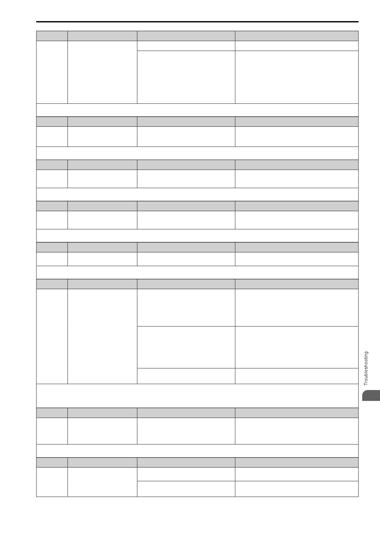
LoG
Log Com Error
There is not a micro SD in the keypad.
Put a micro SD card in the keypad.
• The drive is connected to USB.
Set o5-01 = 0 [Log Start Selection = OFF].
• The number of log communication files is more
than 1000.
• The micro SD card does not have available
memory space.
• The line number data in a log communication
file was changed.
• A communication error between the keypad and
drive occurred during a log communication.
Note:
If the drive detects this error, the terminal assigned to H2-01 to H2-03 = 6A [MFDO Function Select = DataLog Error] will be ON.
Code
Name
Causes
Possible Solutions
LT-1
Cooling Fan Maintenance Time
The cooling fan is at 90% of its expected
1.
Use the procedures in this manual to replace the cooling fan.
performance life.
2.
Set o4-03 = 0 [Fan.Oper Setting = 0 h] to reset the cooling
fan operation time.
Note:
When the estimated performance life is expired, the terminal assigned to H2-01 to H2-03 = 63 [MFDO Function Select = Maintenance] will be ON.
Code
Name
Causes
Possible Solutions
LT-2
Capacitor Maintenance Time
The capacitors for the main circuit and control
Replace the board or the drive. For information about replacing
circuit are at 90% of expected performance life.
the control board, contact the manufacturer or your nearest sales
representative.
Note:
When the estimated performance life is expired, the terminal assigned to H2-01 to H2-03 = 63 [MFDO Function Select = Maintenance] will be ON.
Code
Name
Causes
Possible Solutions
LT-3
SoftChargeBypassRelay
The soft charge bypass relay is at 90% of its
Replace the board or the drive. For information about replacing
MainteTime
expected performance life.
the control board, contact the manufacturer or your nearest sales
representative.
Note:
When the estimated performance life is expired, the terminal assigned to H2-01 to H2-03 = 63 [MFDO Function Select = Maintenance] will be ON.
Code
Name
Causes
Possible Solutions
LT-4
IGBT Maintenance Time (50%)
The IGBT is at 50% of its expected performance
Check the load, carrier frequency, and output frequency.
life.
Note:
When the estimated performance life is expired, the terminal assigned to H2-01 to H2-03 = 63 [MFDO Function Select = Maintenance] will be ON.
Code
Name
Causes
Possible Solutions
oH
Heatsink Overheat
The ambient temperature is high and the heatsink
• Measure the ambient temperature.
temperature is more than the L8-02 [Overheat Alm
• Increase the airflow around the drive.
Level].
• Install a cooling device (cooling fan or air conditioner) to
lower the ambient temperature.
• Remove objects near the drive that are producing too much
heat.
There is not sufficient airflow around the drive.
• Give the drive the correct installation space as shown in the
manual.
• Make sure that there is sufficient circulation around the control
panel.
• Examine the drive for dust or other unwanted materials that
could clog the cooling fan.
• Remove unwanted materials that prevent air circulation.
The internal cooling fan or fans have stopped.
1.
Use the procedures in this manual to replace the cooling fan.
2.
Set o4-03 = 0 [Fan.Oper Setting = 0 h].
Note:
• The drive detects this error if the heatsink temperature of the drive is more than L8-02.
• If the drive detects this error, the terminal set to H2-01 to H2-03 = 4 [MFDO Function Selection = Alarm] will activate.
7
• If the drive detects this error, it will operate the motor as specified by the stopping method set in L8-03 [Overheat Pre-Alarm Selection].
Code
Name
Causes
Possible Solutions
oH2
External Overheat (H1-XX=7D)
An external device sent an oH2.
1.
Find the external device that output the overheat alarm.
2.
Remove the cause of the problem.
3.
Clear the Overheat Alarm (oH2) [H1-xx = 7D] set to MFDI
terminals DI1 to DI7.
Note:
If the drive detects this error, the terminal set to H2-01 to H2-03 = 4 [MFDO Function Selection = Alarm] will activate.
Code
Name
Causes
Possible Solutions
oH3
Motor Overheat (PTC Input)
The thermistor wiring that detects motor
Correct wiring errors.
temperature is defective.
A fault occurred on the machine.
Examine the machine and remove the cause of the fault
Example: The machine is locked.
243
7.5 Minor Faults/Alarms
Code
Name
Causes
Possible Solutions
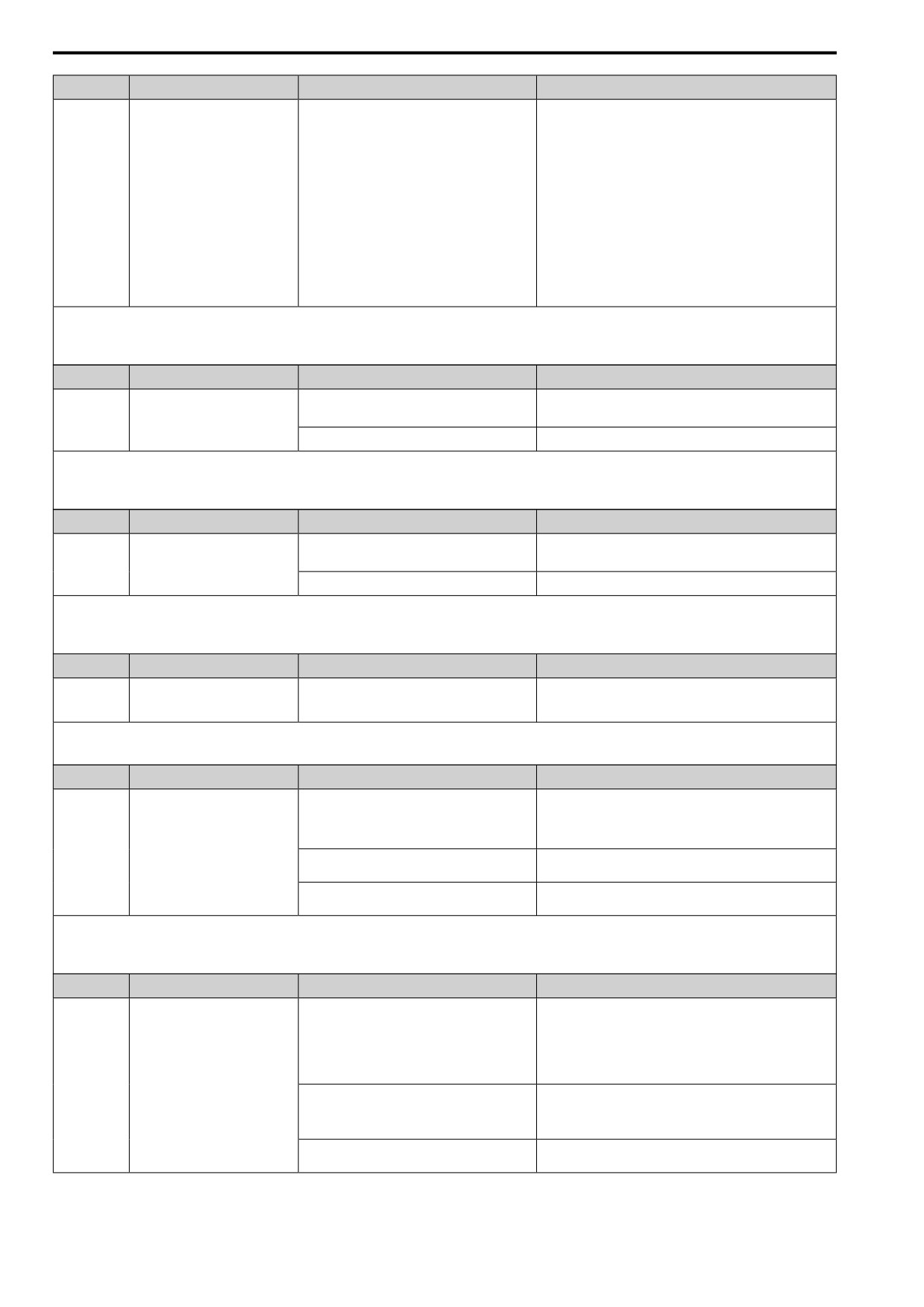
The motor has overheated.
• Check the load level, acceleration/deceleration time, and motor
start/stop frequency (cycle time).
• Decrease the load.
• Increase the values set in C1-01 to C1-08 [Acceleration/
Deceleration Times].
• Set E2-01 [Mot Rated Current (FLA)] correctly to the value
specified by the motor nameplate.
• Make sure that the motor cooling system is operating correctly,
and repair or replace it if it is damaged.
• Adjust E1-04 to E1-10 [V/f Pattern Parameters]. For motor 2,
adjust E3-04 to E3-10. Decrease the values set in E1-08 [Mid
A Voltage] and E1-10 [Min Output Voltage].
Note:
If the values set in E1-08 and E1-10 are too low, the overload
tolerance will decrease at low speeds.
Note:
• The drive detects this fault if the motor overheat signal input from analog input terminal AI1 or AI2 is more than the fault detection level.
• If the drive detects this error, the terminal set to H2-01 to H2-03 = 4 [MFDO Function Select = Alarm] will activate.
• If the drive detects this error, it will operate the motor as specified by the stopping method set in L1-03 [Motor oH AL Reaction Select].
Code
Name
Causes
Possible Solutions
oL3
Overtorque 1
A fault occurred on the machine.
Examine the machine and remove the cause of the fault
Example: The machine is locked.
The parameters are incorrect for the load.
Adjust L6-02 [Trq Det1 Level] and L6-03 [Trq Det1 Time].
Note:
• The drive detects this fault if the drive output current is more than the level set in L6-02 for longer than L6-03.
• If the drive detects this error, the terminal set to H2-01 to H2-03 = 4 [MFDO Function Select = Alarm] will activate.
• Set the conditions that trigger the minor fault using L6-01 [Trq Det1 Select].
Code
Name
Causes
Possible Solutions
oL4
Overtorque 2
A fault occurred on the machine.
Examine the machine and remove the cause of the fault
Example: The machine is locked.
The parameters are incorrect for the load.
Adjust L6-05 [Trq Det2 Level] and L6-06 [Trq Det2 Time].
Note:
• The drive detects this error if the drive output current is more than the level set in L6-05 for longer than L6-06.
• If the drive detects this error, the terminal set to H2-01 to H2-03 = 4 [MFDO Function Select = Alarm] will activate.
• Set the conditions that trigger the minor fault using L6-04 [Trq Det2 Select].
Code
Name
Causes
Possible Solutions
oL5
Mechanical Weakening Detection 1
The drive detected overtorque as specified by the
Do a deterioration diagnostic test on the machine side.
conditions for mechanical weakening detection set
in L6-08 [MechF Enable].
Note:
• If the drive detects this error, the terminal set to H2-01 to H2-03 = 4 [MFDO Function Select = Alarm] will activate.
• If the drive detects this error, it will operate the motor as specified by the Stopping Method set in L6-08.
Code
Name
Causes
Possible Solutions
oS
Overspeed
There is overshoot.
• Decrease C5-01 [ASR PGain 1] and increase C5-02 [ASR
ITime 1].
• Adjust the pulse train gain with H6-02 to H6-05 [Pulse Train
Input Setting Parameters].
There is an incorrect number of PG pulses set in the
Set H6-02 [PI Frequency Scale] to the pulse train frequency
drive.
during 100% reference (maximum motor rotation speed).
The oS detection level is set incorrectly.
Adjust F1-08 [Overspeed Level] and F1-09 [Overspeed Delay
Time].
Note:
• The drive detects this error if the motor speed is more than the value set in F1-08 for longer than F1-09.
• If the drive detects this error, the terminal set to H2-01 to H2-03 = 4 [MFDO Function Selection = Alarm] will activate.
• If the drive detects this error, it will operate the motor as specified by the stopping method set in F1-03 [Overspeed Detection Selection].
Code
Name
Causes
Possible Solutions
ov
Overvoltage
There are surge voltages in the input power supply.
Connect a DC reactor to the drive.
Note:
If you turn the phase advancing capacitors ON and OFF and
use thyristor converters in the same power supply system,
there can be surge voltages that irregularly increase the input
voltage.
The drive output cable or motor is shorted to ground
1.
Examine the motor main circuit cable, terminals, and motor
(the current short to ground is charging the main
terminal box, and then remove ground faults.
circuit capacitor of the drive through the power
2.
Re-energize the drive.
supply).
The power supply voltage is too high.
Decrease the power supply voltage to match the drive rated
voltage.
244
7.5 Minor Faults/Alarms
Code
Name
Causes
Possible Solutions
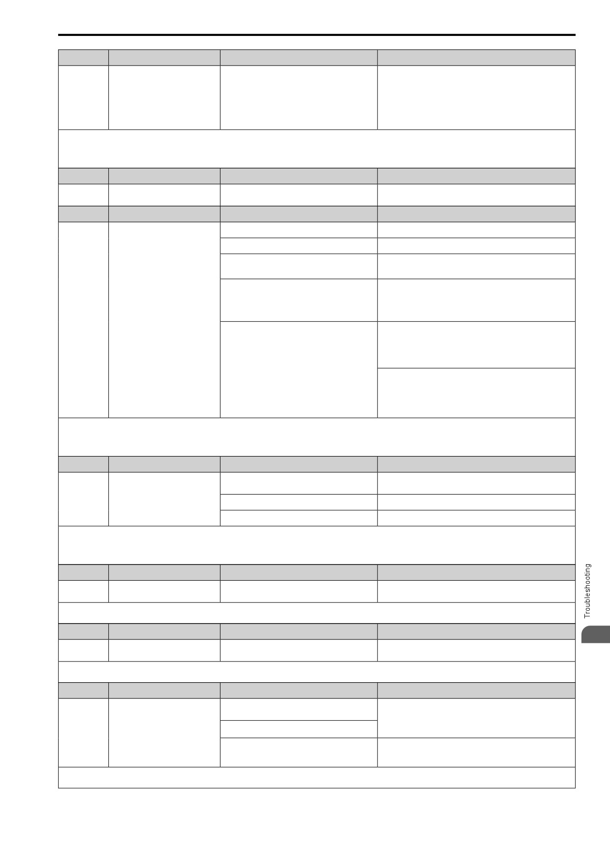
Electrical interference caused a drive malfunction.
• Examine the control circuit lines, main circuit lines, and
ground wiring, and decrease the effects of electrical
interference.
• Make sure that a magnetic contactor is not the source of the
electrical interference, then use a Surge Protective Device if
necessary.
• Set L5-01 ≠ 0 [Auto-Reset Attempts ≠ 0 times].
Note:
• The drive detects this error if the DC bus voltage is more than the ov detection level when the Run command has not been input (while the drive is stopped).
• The ov detection level is approximately 410 V with 200 V class drives. The detection level is approximately 820 V for 400 V class drives.
• If the drive detects this error, the terminal set to H2-01 to H2-03 = 4 [MFDO Function Select = Alarm] will activate.
Code
Name
Causes
Possible Solutions
PASS
Modbus Communication Test
The Modbus communications test is complete.
The PASS display will turn off after communications test mode is
cleared.
Code
Name
Causes
Possible Solutions
PF
Input Phase Loss
There is a phase loss in the drive input power.
Correct all wiring errors with the main circuit power supply.
Loose wiring in the input power terminals.
Tighten the screws to the correct tightening torque.
The drive input power voltage is changing too
• Examine the supply voltage for problems.
much.
• Make the drive input power stable.
Unsatisfactory balance between voltage phases.
• Examine the supply voltage for problems.
• Make the drive input power stable.
• If the supply voltage is good, examine the magnetic contactor
on the main circuit side for problems.
The main circuit capacitors have become
• Examine the capacitor maintenance time in monitor U4-05
unserviceable.
[Capacitor Maintenance].
• If U4-05 is more than 90%, replace the capacitor. Contact the
manufacturer or your nearest sales representative for more
information.
• Examine the supply voltage for problems.
• Re-energize the drive.
• If the alarm stays, replace the circuit board or the drive. For
information about replacing the control board, contact the
manufacturer or your nearest sales representative.
Note:
• The drive detects this error if the DC bus voltage changes irregularly without regeneration.
• If the drive detects this error, the terminal assigned to H2-01 to H2-03 = 4 [MFDO Function Select = Alarm] will be ON.
• Use L8-05 [In PhaseLoss Selection] to enable and disable PF detection.
Code
Name
Causes
Possible Solutions
PGo
Encoder (PG) Feedback Loss
The encoder cable is disconnected or wired
Examine for wiring errors or disconnected wires in the encoder
incorrectly.
cable, and repair problems.
The encoder is not receiving power.
Examine the encoder power supply.
The holding brake is stopping the motor.
Release the holding brake.
Note:
• The drive detects this error if it does not receive the speed detection pulse signal from the encoder in the detection time set in F1-14 [Encoder Open-Circuit Detect Time].
• If the drive detects this error, the terminal assigned to H2-01 to H2-03 = 4 [MFDO Function Select = Alarm] will activate.
• If the drive detects this error, it will operate the motor as specified by the stopping method set in F1-02 [PGOpen Detection Select].
Code
Name
Causes
Possible Solutions
rUn
Motor Switch during Run
The drive received a Motor 2 Select [H1-xx = 61]
Make sure that the drive receives the Motor 2 Selection while the
during run.
drive is stopped.
Note:
If the drive detects this error, the terminal set to H2-01 to H2-03 = 4 [MFDO Function Select = Alarm] will activate.
Code
Name
Causes
Possible Solutions
7
SE
Modbus Test Mode Error
Modbus communications self-diagnostics [H1-xx =
Stop the drive and do Modbus communications self-diagnostics.
7F] was done while the drive was running.
Note:
If the drive detects this error, the terminal set to H2-01 to H2-03 = 4 [MFDO Function Select = Alarm] will activate.
Code
Name
Causes
Possible Solutions
SToF
Safe Torque OFF Failure
One of the two terminals H1-HC and H2-HC
• Make sure that the Safe Disable signal is input from an
received the Safe Disable input signal.
external source to terminals H1-HC or H2-HC.
• When the Safe Disable function is not in use, connect
The Safe Disable input signal is wired incorrectly.
terminals H1-HC and H2-HC.
There is internal damage to one Safe Disable
Replace the board or the drive. For information about replacing
channel.
the control board, contact the manufacturer or your nearest sales
representative.
Note:
If the drive detects this error, the terminal assigned to H2-01 to H2-03 = 4 [MFDO Function Select = Alarm] will be ON.
245
7.5 Minor Faults/Alarms
Code
Name
Causes
Possible Solutions
TiM
Keypad Time Not Set
There is a battery in the keypad, but the date and
Set the date and time with the keypad.
time are not set.
Note:
• Parameter o4-24 [bAT Detection Selection] enables and disables TiM detection.
• If the drive detects this error, the terminal set to H2-01 to H2-03 = 4 [MFDO Function Select = Alarm] will activate.
Code
Name
Causes
Possible Solutions
TrPC
IGBT Maintenance Time (90%)
The IGBT is at 90% of its expected performance
Replace the IGBT or the drive. For information about replacing
life.
the control board, contact the manufacturer or your nearest sales
representative.
Note:
If the drive detects this error, the terminal set to H2-01 to H2-03 = 4 [MFDO Function Selection = Alarm] will activate.
Code
Name
Causes
Possible Solutions
UL3
Undertorque Detection 1
A fault occurred on the machine.
Examine the machine and remove the cause of the fault
Example: There is a broken pulley belt.
The parameters are incorrect for the load.
Adjust L6-02 [Trq Det1 Level] and L6-03 [Trq Det1 Time].
Note:
• The drive detects this error if the drive output current is less than the level set in L6-02 for longer than L6-03.
• If the drive detects this error, the terminal set to H2-01 to H2-03 = 4 [MFDO Function Select = Alarm] will activate.
• Set the conditions that trigger the minor fault using L6-01 [Trq Det1 Select].
Code
Name
Causes
Possible Solutions
UL4
Undertorque Detection 2
A fault occurred on the machine.
Examine the machine and remove the cause of the fault
Example: There is a broken pulley belt.
The parameters are incorrect for the load.
Adjust L6-05 [Trq Det2 Level] and L6-06 [Trq Det2 Time].
Note:
• The drive detects this error if the drive output current is less than the level set in L6-05 for longer than L6-06.
• If the drive detects this error, the terminal set to H2-01 to H2-03 = 4 [MFDO Function Select = Alarm] will activate.
• Set the conditions that trigger the minor fault using L6-04 [Trq Det2 Select].
Code
Name
Causes
Possible Solutions
UL5
Mechanical Weakening Detection 2
The drive detected undertorque as specified by the
Examine the machine for deterioration.
conditions for mechanical weakening detection set
in L6-08 [MechF Enable].
Note:
• If the drive detects this error, the terminal set to H2-01 to H2-03 = 4 [MFDO Function Select = Alarm] will activate.
• If the drive detects this error, it will operate the motor as specified by the Stopping Method set in L6-08.
Code
Name
Causes
Possible Solutions
Uv
DC Bus Undervoltage
The drive input power voltage is changing too
• Use a better power supply voltage to align with the drive rated
much.
voltage.
• Make the drive input power stable.
• If there is not a fault with the input power supply, examine the
magnetic contactor on the main circuit side for faults.
A phase loss occurred in the drive input power.
Correct errors with the wiring for main circuit drive input power.
There is loose wiring in the drive input power
Examine for loose screws and tighten them as specified by the
terminals.
tightening torque values in the manual.
There was a loss of power.
Use a better power supply.
The main circuit capacitors have deteriorated.
Examine the capacitor maintenance time in monitor U4-05
[Capacitor Maintenance]. If U4-05 is more than 90%, replace the
control board or the drive. For information about replacing the
control board, contact the manufacturer or your nearest sales
representative.
The drive input power transformer is too small and
• Check for an alarm when a molded-case circuit breaker,
voltage drops when the power is switched on.
Leakage Breaker (ELCB, GFCI, or RCM/RCD) (with
overcurrent protective function), or magnetic contactor is ON.
• Check the capacity of the drive power supply transformer.
Air inside the drive is too hot.
Measure the ambient temperature of the drive.
The Charge LED is broken.
Replace the board or the drive. For information about replacing
the control board, contact the manufacturer or your nearest sales
representative.
Note:
• The drive detects this error if one of these conditions is correct when the Run command has not been input (while the drive is stopped).
-The DC bus voltage < L2-05 [UV Detection Lvl (Uv1)].
-The Contactor that prevents inrush current in the drive was opened.
-There is low voltage in the control drive input power.
• If the drive detects this error, the terminal set to H2-01 to H2-03 = 4 [MFDO Function Select = Alarm] will activate.
246
7.6 Parameter Setting Errors
7.6
Parameter Setting Errors
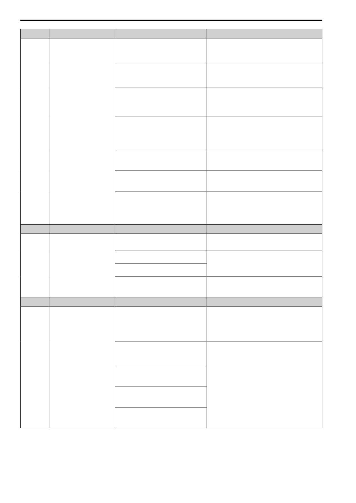
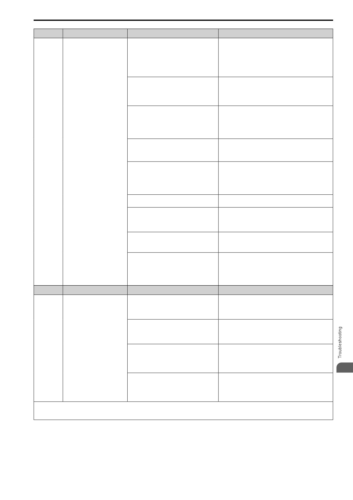
Parameter setting errors occur when multiple parameter settings do not agree, or when parameter setting values
are not correct.
Examine the parameter setting that caused the error, and remove the cause of the error. You must first correct the
parameter setting errors before you can operate the drive. The drive will not send notification signals for the faults
and alarms when these parameter setting errors occur.
Code
Name
Causes
Possible Solutions
oPE01
Drive Capacity Setting Error
The value set in o2-04 [Drive KVA Selection] does
Set o2-04 to the correct value.
not agree with the drive model.
Code
Name
Causes
Possible Solutions
oPE02
Parameter Range Setting Error
Parameters settings are not in the applicable setting
range.
1.
Push
to show U1-18 [oPE Fault Parameter], and find
parameters that are not in the applicable setting range.
2.
Correct the parameter settings.
Note:
If more than one error occurs at the same time, other oPExx
errors have priority over oPE02.
Set E2-01 ≤ E2-03 [Mot Rated Current (FLA) ≤
Make sure that E2-01 > E2-03.
Mot No-Load Current].
Note:
If it is necessary to set E2-01 < E2-03, first lower the value
set in E2-03, and then set E2-01.
Code
Name
Causes
Possible Solutions
oPE03
Multi-Function Input Setting Err
The settings for these parameters do not agree:
Correct the parameter settings.
• H1-01 to H1-07 [Terminals DI1 to DI7 Function
Selection]
• H7-01 to H7-04 [Virtual Multi-Function Inputs 1
to 4]
The settings for MFDIs overlap.
Set the parameters correctly to prevent MFDI function overlap.
Note:
This does not include H1-xx = 20 to 2F [MFDI
Function Select = External Fault] and
[Reserved].
These pairs of MFDI functions are not set to Digital
Set the MFDI pairs.
Inputs (H1-xx and H7-01 to H7-04) at the same
time:
• Setting values 62 [Up Command] and 63 [Down
Command]
• Setting values 65 [Up2 Command] and 66 [Dw2
Command]
• Setting values 3 [Run Command] and 4 [FWD/
REV Cmd]
A minimum of two of these MFDI combinations are
Remove the function settings that are not in use.
set to Digital Inputs (H1-xx and H7-01 to H7-04) at
the same time:
• Setting values 62 [Up Command] and 63 [Down
Command]
• Setting values 65 [Up2 Command] and 66 [Dw2
Command]
• Setting value 17 [Ac/Dec Hold]
• Setting value 16 [Ref Sample]
• Setting values E to 10 [Add Offset Frequency 1
to 3 (d7-01 to d7-03)]
These commands are set in Digital Inputs (H1-xx
Remove the function settings that are not in use.
and H7-01 to H7-04) at the same time:
• Setting values 67 [SpdSrch Fmax] and 68
7
[SpdSrch Fref]
• Setting values 40, 41, 42, 43 [KEB Thru1 NC,
KEB Thru1 NO, KEB Thru2 NC, KEB Thru2
NO] and 32 [HiSlipBraking]
• Setting values 61 [Motor 2 Select] and 19 [Ac/
Dec Time2]
• Setting values 40, 41 [KEB Thru1 NC, KEB
Thru1 NO] and 42, 43 [KEB Thru2 NC, KEB
Thru2 NO]
• Setting values 1, 2 [Forward Run, Reverse Run]
and 3, 4 [Run Command, FWD/REV Cmd]
• Setting values 30 [DCInj Cmd] and 1A [Drive
Enable]
• Setting values 61 [Motor 2 Select] and 65, 66
[Up2 Command, Dw2 Command]
247
7.6 Parameter Setting Errors
Code
Name
Causes
Possible Solutions
Settings for N.C. and N.O. input [H1-xx] for these
Remove one of the function settings.
functions were selected at the same time:
• Setting value 34 [Fast Stop NO]
• Setting value 35 [Fast Stop NC]
These settings were entered while H1-xx = 9 [Ext
Set H6-01 = 0.
Ref 1/2]:
• b1-15 = 4 [Freq. Ref. Sel. 2 = Pulse Train Input]
• H6-01 ≠ 0 [PI Pulse Train Function ≠ Freq Ref]
These settings were entered while H1-xx = 9 [Ext
Connect an input option to the drive.
Ref 1/2]:
• b1-15 = 3 [Option PCB] or b1-16 = 3 [Run
Comm. Sel 2 = Option PCB]
• No option is connected to the drive.
These settings were entered while H1-xx = 9 [Ext
Set H3-02 = 0 or H3-10 = 0.
Ref 1/2]:
• b1-15 = 1 [Analog Input]
• H3-02 ≠ 4 [AI1 Function Selection ≠ Freq Ref/
BIAS] or H3-10 ≠ 0 [AI2 Function Selection ≠
Freq Ref/BIAS]
These parameters are set at the same time:
Correct the parameter settings.
• H1-xx ≠ 1A [Drive Enable]
• H2-xx = 2 [Drive Enable]
These parameters are set at the same time:
Correct the parameter settings.
• H6-01 ≠ 3 [PG Feedback]
• H1-xx = 15 [FWD/REV Det]
These parameters are set at the same time:
Remove one of the function settings.
• H1-xx = 65/66 [Up2 Command / Dw2
Command]
• H3-01, H3-09 = 1 [AI1 Signal Level Select, AI2
Signal Level Select = 0 to +10 V (Without Lower
Limit)]
Code
Name
Causes
Possible Solutions
oPE05
Run Cmd/Freq Ref Source Sel Err
The setting to assign the Run command or
Correct the parameter settings.
frequency reference to an option card or the pulse
train input is incorrect.
b1-01 = 3 [Freq. Ref. Sel. 1 = Option PCB] is set,
Connect an option card to the drive.
but there is no option card connected to the drive.
b1-02 = 3 [Run Comm. Sel 1 = Option PCB] is set,
but there is no option card connected to the drive.
These parameters are set at the same time:
Set H6-01 = 0.
• b1-01 = 4 [Pulse Train Input]
• H6-01 ≠ 0 [PI Pulse Train Function ≠ Freq Ref]
Code
Name
Causes
Possible Solutions
oPE07
Analog Input Selection Error
The settings for H3-02 and H3-10 [MFAI Function
Set H3-02, H3-10, and H7-30 correctly to prevent overlap.
Select] and H7-30 [Virtual AIn Select Function]
Note:
overlap.
It is possible to set these functions to multiple analog input
terminals at the same time:
• Setting value 4 [Freq Ref/BIAS]
• Setting values 0 [Through Mode]
These parameters are set at the same time:
Remove the function settings that are not in use.
• H3-02, H3-10, H7-30 = F [PID Fbk]
• H6-01 = 1 [PI Pulse Train Function = PIDFbk
Value]
These parameters are set at the same time:
• H3-02, H3-10, H7-30 = 10 [PID SetPoint]
• H6-01 = 2 [PID SP Value]
These parameters are set at the same time:
• H3-02, H3-10, H7-30 = 10
• b5-18 = 1 [b5-19 PID SP Selection = Enabled]
These parameters are set at the same time:
• H6-01 = 2
• b5-18 = 1
248
7.6 Parameter Setting Errors
Code
Name
Causes
Possible Solutions
oPE08
Parameter Selection Error
A function was set that is not compatible with the
1.
Push ENTER Key to show U1-18 [oPE Fault Parameter],
control method selected in A1-02 [Control Method].
and find parameters that are not in the applicable setting
range.
2.
Correct the parameter settings.
Note:
If more than one error occurs at the same time, other oPExx
errors have priority over oPE02.
When A1-02 = 2 [OLVector], you used these
• Set n2-02 < n2-03.
parameter settings:
• Set C4-02 < C4-06.
• n2-02 > n2-03 [AFR Time 1 > AFR Time 2]
• C4-02 > C4-06 [Trq Comp Delay Time > M2
Trq Comp Delay Time]
When A1-02 = 0 [V/f Control], you used these
Correct the parameter settings.
parameter settings:
Note:
• H6-01 = 3 [PI Pulse Train Function = PG
You cannot use Speed Feedback (V/F Control) with the Motor
Feedback]
Switch function.
• H1-xx = 61 [MFDI Function Select = Motor 2
Select]
When A1-02 = 5 [PM OLVector], you set E5-02 to
• Set E5-01 [PM Mot Code Selection] correctly as specified by
E5-07 [PM q-Axis Inductance (mH/Phase)] = 0.
the motor.
• For specialized motors, refer to the motor test report and set
E5-xx correctly.
When A1-02 = 5, 6 [PM OLVector, PM
Set E5-09 or E5-24 to the correct value.
AOLVector], you used these parameter settings:
• E5-09 = 0.0 [PM BackEMF Vpeak (mV/(rad/ s))
= 0.0 mV/(rad/s)]
• E5-24 = 0.0 [PM BackEMF L-L Vrms (mV/rpm)
= 0.0 mV/min-1]
When A1-02 = 5, 6, you set E5-09 ≠ 0 and E5-24 ≠
Set E5-09 = 0 or E5-24 = 0.
0.
When A1-02 = 6, you set these parameters:
Correct the parameter settings.
• n8-57 = 0 [High-Freq Injection = Disabled]
• You set E1-09 [Min Output Frequency] < the
5% value of E1-06.
When A1-02 = 6, you set these parameters:
Correct the parameter settings.
• n8-35 = 1 [InitRotorPos Selection = Pull-In]
• n8-57 = 1 [Enabled]
When A1-02 = 8 [EZ Vector], you used these
When E9-01 = 1 or 2, set b3-24 = 1 [Speed Estimation].
parameter settings:
• E9-01 = 1, 2 [Motor Type Selection = PM,
SynRM]
• b3-24 = 2 [SpSrch Method Selection = Current
Det2]
Code
Name
Causes
Possible Solutions
oPE09
PID Control Selection Fault
These parameters are set at the same time:
• Set b5-15 ≠ 0.0.
• b5-15 ≠ 0.0 [Sleep Start Level ≠ 0.0 Hz]
• Set b1-03 = 0, 1 [Ramp->Stop, Coast->Stop].
• b1-03 = 2, 3 [Stopping Method Selection = DC
Inj->Stop, Timed Coast->Stop]
These parameters are set at the same time:
Correct the parameter settings.
• b5-01 = 1 [Enabled] and b5-72 = 0, 1 [PID D-
FF Mode = D=Fdback, D=FdFwd]
• d2-02 ≠ 0.0 [FRef Lower Limit ≠ 0.0%]
These parameters are set at the same time:
Correct the parameter settings.
• b5-01 = 1 and b5-72 = 0, 1 [D=Fdback, D=
FdFwd]
• b5-11 = 1 [PID Output Reverse Selection =
Negative lower limit]
7
These parameters are set at the same time:
Correct the parameter settings.
• b5-01 = 1 and b5-70 = 1 [PID MainRefMode =
Fref + PID] and B5-72 = 0, 1 [D=Fdback, D=
FdFwd]
• d2-02 ≠ 0.0 has been set.
Note:
The drive detects this error if the PID control function selection is incorrect.
(When b5-01 = 1 [PID Enable = Enabled])
249
7.6 Parameter Setting Errors
Code
Name
Causes
Possible Solutions
oPE10
V/f Data Setting Error
The parameters that set the V/f pattern do not
Set the parameters correctly to satisfy the conditions.
satisfy these conditions:
• For motor 1: E1-09 ≤ E1-07 < E1-06 ≤ E1-11 ≤
E1-04 [Min Output Frequency ≤ Mid A
Frequency < Base Frequency ≤ Mid B
Frequency ≤ Max Output Frequency]
• For motor 2: E3-09 ≤ E3-07 < E3-06 ≤ E3-11 ≤
E3-04 [M2 Min Out Frequency ≤ M2 Mid A
Frequency < M2 Base Frequency ≤ M2 Mid B
Frequency ≤ M2 Max Out Frequency]
Code
Name
Causes
Possible Solutions
oPE11
Carrier Frequency Setting Error
These parameters are set at the same time:
Set C6-02 to C6-05 correctly.
• C6-05 > 6 [Carrier Freq Proportional Gain >
6]
• C6-04 > C6-03 [Carrier Lower Frequency Limit
> Carrier Upper Frequency Limit]
Note:
When C6-05 < 7, C6-04 becomes disabled. The
drive sets the carrier frequency to the value set
to C6-03.
C6-02 to C6-05 settings are not in the applicable
setting range.
Code
Name
Causes
Possible Solutions
oPE13
Pulse Monitor Selection Error
H6-06 = 101, 102, 105, or 116 [PO Mon.Selection
Set H6-06 correctly.
= Frequency Reference, Output Frequency, Motor
Speed, Output Frequency after Soft Starter] has not
been set when H6-07 = 0 [PO Freq.Scaling = 0
Hz].
Code
Name
Causes
Possible Solutions
oPE16
Energy Saving Constants Error
The Energy Saving parameters are not set in the
Make sure that E5-xx is set correctly as specified by the motor
applicable setting range.
nameplate data.
Code
Name
Causes
Possible Solutions
oPE33
Digital Output Selection Error
These two parameters are set at the same time:
Clear the H2-01 to H2-03 = 1xx [Inverse output of xx] settings.
• H2-60 ≠ 0 [NO,NC,CM 2nd Function ≠ Through
Note:
Mode]
If you use the function to output logical calculation results
• H2-01 = 1xx [NO,NC,CM FuncSelection =
(H2-60, H2-63, H2-66 ≠ 0), you cannot set H2-01 to H2-03 =
Inverse output of xx]
1xx.
These two parameters are set at the same time:
• H2-63 ≠ 0 [DO1 2nd Function ≠ Through Mode]
• H2-02 = 1xx [DO1-O1C Func Selection =
Inverse output of xx]
These two parameters are set at the same time:
• H2-66 ≠ 0 [DO2 2nd Function ≠ Through Mode]
• H2-03 = 1xx [DO2-O2C Func Selection =
Inverse output of xx]
These parameter pairs are set incorrectly:
• Set parameters H2-21 ≤ H2-22.
• H2-21 [Compare1 Low Limit] > H2-22
• Set parameters H2-27 ≤ H2-28.
[Compare1 Up Limit]
• H2-27 [Compare2 Low Limit] > H2-28
[Compare2 Up Limit]
250
7.7 Auto-Tuning Errors
7.7
Auto-Tuning Errors
If the drive detects an Auto-Tuning error, the keypad will show the error and the motor will coast to stop.
The drive will not send notification signals for faults and alarms when Auto-Tuning errors occur.
Two types of Auto-Tuning errors are: Endx and Erx:
•
Endx identifies that Auto-Tuning has successfully completed with calculation errors. Find and repair the cause
of the error and do Auto-Tuning again, or set the motor parameters manually. You can use the drive in the
application if you cannot find the cause of the Endx error.
•
Erx identifies that Auto-Tuning was not successful. Find and repair the cause of the error and do Auto-Tuning
again.
Code
Name
Causes
Possible Solutions
End1
Excessive Rated Voltage Setting
The torque reference was more than 20% during
• Make sure that the input motor nameplate data is correct.
Auto-Tuning or the no-load current that was
• Do Auto-Tuning again and correctly set the motor nameplate
measured after Auto-Tuning is more than 80%.
data.
• If you can uncouple the motor and load, remove the motor
from the machine and do Rotational Auto-Tuning again.
• If you cannot uncouple the motor and load, use the results
from Auto-Tuning.
Code
Name
Causes
Possible Solutions
End2
Iron Core Saturation Coefficient
The motor nameplate data entered during Auto-
• Make sure that the input motor nameplate data is correct.
Tuning is incorrect.
• Do Auto-Tuning again and correctly set the motor nameplate
data.
Auto-Tuning results were not in the applicable
• Examine and repair damaged motor wiring.
parameter setting range, and E2-07 or E2-08 [Mbus
• If you can uncouple the motor and load, remove the motor
Reg1 Bit Select] have temporary values.
from the machine and do Rotational Auto-Tuning again.
Code
Name
Causes
Possible Solutions
End3
Rated Current Setting Alarm
The rated current value is incorrect.
Do Auto-Tuning again and set the correct rated current shown on
the motor nameplate.
Code
Name
Causes
Possible Solutions
End4
Adjusted Slip Calculation Error
The Auto-Tuning results were not in the applicable
• Make sure the input motor nameplate data is correct.
parameter setting range.
• Do Rotational Auto-Tuning again and correctly set the motor
nameplate data.
The motor rated slip that was measured after
Stationary Auto-Tuning was 0.2 Hz or lower.
• If you cannot uncouple the motor and load, do Stationary
Auto-Tuning 2.
The motor rated slip that was measured after
compensation with E2-08 [Mbus Reg1 Bit Select] is
not in the applicable range.
The secondary resistor measurement results were
not in the applicable range.
Code
Name
Causes
Possible Solutions
End5
Resistance Tuning Error
The Auto-Tuning results of the Line-to-Line
• Make sure that the input motor nameplate data is correct.
Resistance were not in the applicable range.
• Examine and repair damaged motor wiring.
Code
Name
Causes
Possible Solutions
End6
Leakage Inductance Alarm
The Auto-Tuning results were not in the applicable
Make sure that the input motor nameplate data is correct, and do
parameter setting range.
Auto-Tuning again.
A1-02 [Control Method] setting is not applicable.
• Examine the value set in A1-02.
• Make sure that the input motor nameplate data is correct, and
do Auto-Tuning again.
Code
Name
Causes
Possible Solutions
End7
No-Load Current Alarm
The Auto-Tuning results of the motor no-load
Examine and repair damaged motor wiring.
7
current value were not in the applicable range.
Auto-Tuning results were less than 5% of the motor
Make sure that the input motor nameplate data is correct, and do
rated current.
Auto-Tuning again.
Code
Name
Causes
Possible Solutions
End8
HFI Alarm
• Inductance saliency ratio (E5-07/E5-06) is too
• Set the correct value on the motor nameplate to [E5: PM
small.
MOTOR SETTINGS] or do rotational/stationary Auto-Tuning.
• The drive cannot find the n8-36 [HFI Signal
• When it is necessary to set n8-35 = 2 [InitRotorPos Selection
Frequency] value.
= HiFreq Injection] or n8-57 = 1 [High-Freq Injection =
Enabled], make sure that there is no unusual noise in the low
speed range (10% or less) and that the motor does not rotate in
reverse at start.
Note:
If the drive detects End8, it will automatically set n8-35 =1
[Pull-In] and n8-57 = 0 [Disabled]. Do not change the
settings unless necessary.
251
7.7 Auto-Tuning Errors
Code
Name
Causes
Possible Solutions
End9
Initial Pole Detection Alarm
The drive cannot calculate the correct value for n8-
When n8-35 = 2 [InitRotorPos Selection = HiFreq Injection] or
84 [Polarity Det Current] during High Frequency
n8-57 = 1 [High-Freq Injection = Enabled], make sure that the
Injection Tuning.
motor does not rotate in reverse at start.
Note:
If the drive detects End9, it will automatically set n8-35 =1
[Pull-In] and n8-57 = 0 [Disabled]. Do not change the
settings unless necessary.
Code
Name
Causes
Possible Solutions
Er-01
Motor Data Error
The motor nameplate data entered during Auto-
• Make sure that the motor nameplate data is correct.
Tuning is incorrect.
• Do Auto-Tuning again and correctly set the motor nameplate
data.
The combination of the motor rated power and
• Examine the combination of drive capacity and motor output.
motor rated current do not match.
• Do Auto-Tuning again, and correctly set the motor rated power
and motor rated current.
The combination of the motor rated current that was
• Examine the motor rated current and the no-load current.
entered during Auto-Tuning and E2-03 [Mot No-
• Set E2-03 correctly.
Load Current] do not match.
• Do Auto-Tuning again, and correctly set the motor rated
current.
The combination of the setting values of Motor
Do Auto-Tuning again, and correctly set the Motor Base
Base Frequency and Motor Base Speed do not
Frequency and Motor Base Speed.
match.
Code
Name
Causes
Possible Solutions
Er-02
Drive in an Alarm State
The motor nameplate data entered during Auto-
• Make sure that the motor nameplate data entered in Auto-
Tuning is incorrect.
Tuning is correct.
• Do Auto-Tuning again and correctly set the motor nameplate
data.
You did Auto-Tuning while the drive had a minor
Clear the minor fault or alarm and do Auto-Tuning again.
fault or alarm.
There is a defective motor cable or cable
Examine and repair motor wiring.
connection.
The load is too large.
• Decrease the load.
• Examine the machine area to see if, for example, the motor
shaft is locked.
The drive detected a minor fault during Auto-
1.
Stop Auto-Tuning.
Tuning.
2.
Examine the minor fault code and remove the cause of the
prblem.
3.
Do Auto-Tuning again.
Code
Name
Causes
Possible Solutions
Er-03
STOP Button was Pressed
Auto-Tuning did not complete correctly. Do Auto-Tuning again.
During Auto-Tuning,
was pushed.
Code
Name
Causes
Possible Solutions
Er-04
Line-to-Line Resistance Error
The Auto-Tuning results were not in the applicable
• Examine and repair motor wiring.
parameter setting range.
• Disconnect the machine from the motor and do Rotational
Auto-Tuning again.
Auto-Tuning did not complete in a pre-set length of
time.
There is a defective motor cable or cable
connection.
The motor nameplate data entered during Auto-
• Make sure that the input motor nameplate data is correct.
Tuning is incorrect.
• Do Auto-Tuning again and correctly set the motor nameplate
data.
Code
Name
Causes
Possible Solutions
Er-05
No-Load Current Error
The Auto-Tuning results were not in the applicable
• Examine and repair motor wiring.
parameter setting range.
• Disconnect the machine from the motor and do Rotational
Auto-Tuning again.
Auto-Tuning did not complete in a pre-set length of
time.
The motor nameplate data entered during Auto-
• Make sure that the input motor nameplate data is correct.
Tuning is incorrect.
• Do Auto-Tuning again and correctly set the motor nameplate
data.
Rotational Auto-Tuning was done with a load that
• Disconnect the machine from the motor and do Rotational
was more than 30% of the rating connected to the
Auto-Tuning again.
motor.
• If you cannot uncouple the motor and load, make sure that the
load is less than 30% of the motor rating. If a mechanical
brake is installed in the motor, release the brake during
Rotational Auto-Tuning.
252
7.7 Auto-Tuning Errors
Code
Name
Causes
Possible Solutions
Er-08
Rated Slip Error
The motor nameplate data entered during Auto-
• Make sure that the input motor nameplate data is correct.
Tuning is incorrect.
• Do Auto-Tuning again and correctly set the motor nameplate
data.
Auto-Tuning did not complete in a pre-set length of
• Examine and repair the motor wiring.
time.
• If the motor and machine are connected during Rotational
Auto-Tuning, decouple the motor from the machinery.
The Auto-Tuning results were not in the applicable
parameter setting range.
Rotational Auto-Tuning was done with a load that
• Disconnect the machine from the motor and do Rotational
was more than 30% of the rating connected to the
Auto-Tuning again.
motor.
• If you cannot uncouple the motor and load, make sure that the
load is less than 30% of the motor rating. If a mechanical
brake is installed in the motor, release the brake during
Rotational Auto-Tuning.
Code
Name
Causes
Possible Solutions
Er-09
Acceleration Error
The motor did not accelerate for the specified
1.
Increase the value set in C1-01 [Accel Time 1].
acceleration time.
2.
Disconnect the machine from the motor and do Rotational
Auto-Tuning again.
The value of L7-01 or L7-02 [FW Torque Limit or
Increase the value set in L7-01 or L7-02.
RV Torque Limit] is small.
Rotational Auto-Tuning was done with a load that
• Disconnect the machine from the motor and do Rotational
was more than 30% of the rating connected to the
Auto-Tuning again.
motor.
• If you cannot uncouple the motor and load, make sure that the
load is less than 30% of the motor rating. If a mechanical
brake is installed in the motor, release the brake during
Rotational Auto-Tuning.
Code
Name
Causes
Possible Solutions
Er-10
Motor Direction Error
There is defective drive and motor wiring.
Examine and repair motor wiring.
There is defective drive and encoder wiring.
Examine and repair the wiring to the encoder.
The machine pulled the motor to rotate in the
Disconnect the machine from the motor and do Rotational Auto-
opposite direction.
Tuning again.
When the torque reference is 100% or higher, the
sign of the speed reference was opposite of the
detected speed.
Code
Name
Causes
Possible Solutions
Er-11
Motor Speed Error
The torque reference during acceleration is too high
• Increase the value set in C1-01 [Accel Time 1].
(100%).
• Disconnect the machine from the motor and do Rotational
Auto-Tuning again.
Code
Name
Causes
Possible Solutions
Er-12
Current Detection Error
There is a phase loss in the drive input power. (U/
Examine and repair motor wiring.
T1, V/T2, W/T3)
The current exceeded the current rating of the drive.
• Check the motor wiring for any short circuits between the
wires.
The output current is too low.
• Check and turn ON any magnetic contactors used between
motors.
• Replace the control board or the drive. For information about
replacing the control board, contact the manufacturer or your
nearest sales representative.
You tried Auto-Tuning without a motor connected
Connect the motor and do Auto-Tuning.
to the drive.
There was a current detection signal error.
Replace the control board or the drive. For information about
replacing the control board, contact the manufacturer or your
nearest sales representative.
Code
Name
Causes
Possible Solutions
7
Er-13
Leakage Inductance Alarm
The motor rated current value is incorrect.
Correctly set the rated current indicated on the motor nameplate
and perform Auto-Tuning again.
The drive could not complete tuning for leakage
Examine and repair motor wiring.
inductance in fewer than 300 seconds.
Code
Name
Causes
Possible Solutions
Er-14
Motor Speed Error 2
The motor speed was more than two times the
Decrease the value set in C5-01 [ASR PGain 1].
amplitude of speed reference during Inertia Tuning.
Code
Name
Causes
Possible Solutions
Er-15
Torque Saturation Error
During Inertia Tuning, the output torque was more
• Increase the value set in L7-01 to L7-04 [Torque Limit] as
than the value set in L7-01 to L7-04 [Torque Limit].
much as possible.
• Decrease the values set for the frequency and amplitude of the
test signals used when doing inertia tuning. First, decrease the
test signal amplitude, and then do Inertia Tuning. If the error
continues, decrease the test signal frequency and do Inertia
Tuning again.
253
7.7 Auto-Tuning Errors
Code
Name
Causes
Possible Solutions
Er-16
Inertia ID Error
The inertia found by the drive was too small or too
• Decrease the values set for the frequency and amplitude of the
large during Inertia Tuning (10% or less, or
test signals used when doing inertia tuning. First, decrease the
50000% or more).
test signal amplitude, and then do Inertia Tuning. If the error
continues, decrease the test signal frequency and do Inertia
Tuning again
• Correctly set the motor inertia as specified by the motor, and
do Inertia Tuning again.
Code
Name
Causes
Possible Solutions
Er-17
Reverse Prohibited Error
b1-04 = 1 [Reverse Operation Selection =
1.
Enable reverse in the target machine.
Disabled]
2.
Set b1-04 = 0 [Enabled].
Note:
3.
Do Inertia Tuning again.
You cannot do Inertia Tuning if the drive cannot
rotate the motor in reverse.
Code
Name
Causes
Possible Solutions
Er-18
Back EMF Error
The result of the induced voltage tuning was not in
1.
Make sure that the input motor nameplate data is correct.
the applicable range.
2.
Do Auto-Tuning again and correctly set the motor nameplate
data.
Code
Name
Causes
Possible Solutions
Er-19
PM Inductance Error
The Auto-Tuning results of the PM motor
1.
Make sure that the input motor nameplate data is correct.
inductance were not in the applicable range.
2.
Do Auto-Tuning again and correctly set the motor nameplate
data.
Code
Name
Causes
Possible Solutions
Er-20
Stator Resistance Error
The Auto-Tuning results of the PM Motor Stator
1.
Make sure that the input motor nameplate data is correct.
Resistance were not in the applicable range.
2.
Do Auto-Tuning again and correctly set the motor nameplate
data.
Code
Name
Causes
Possible Solutions
Er-25
HighFreq Inject Param Tuning Err
The motor data is incorrect.
Do Stationary Auto-Tuning again.
Note:
If the drive detects Er-25 after doing Stationary Auto-Tuning,
the motor may not be able to use high frequency injection
control. Contact the manufacturer or your nearest sales
representative for more information.
254
7.8 Backup Function Operating Mode Display and Errors
7.8
Backup Function Operating Mode Display and Errors
◆ Operating Mode Display
When you use the LCD keypad to do the backup function, the keypad shows the running operation on the LC
display. These indicators do not show that an error has occurred.
Keypad Display
Name
Display
Status
Drive and Keypad mismatch.
Detection of inconsistency between the
Normally displayed
The drive detected the connection of a keypad from a different
drive and keypad
drive. Select [Yes] to copy parameters backed up in the keypad to
Should the parameters be
the connected drive.
restored?
Restore Restore from keypad
Restoring parameters
Flashing
The parameters stored in the keypad have been restored to the
drive.
End
Backup/restore/verify operation ended
Normally displayed
The parameter backup, restore, or verify operation ended
normally
normally.
Backup Backup from Drive
Backing up parameters
Flashing
The parameters stored in the drive are being backed up to the
keypad.
Verify Keypad & Drive
Verifying parameters
Flashing
The parameter settings stored in the keypad and the parameter
settings in the drive match or are being compared.
◆ Backup Function Error
When an error occurs, the keypad shows a code to identify the error.
Note:
Push any key on the keypad to clear an error.
Code
Name
Causes
Possible Solutions
CPEr
Control Mode Mismatch
The keypad setting and drive setting for A1-02
1.
Set A1-02 on the drive to the same value that is on the
[Control Method] do not agree.
keypad.
2.
Restore the parameters.
Code
Name
Causes
Possible Solutions
CPyE
Error Writing Data
Parameter restore did not end correctly.
Restore the parameters.
Code
Name
Causes
Possible Solutions
CSEr
Control Mode Mismatch
The keypad is broken.
Replace the keypad.
Code
Name
Causes
Possible Solutions
dFPS
Drive Model Mismatch
You tried to restore parameters to a different drive
1.
Examine the drive model that you used to back up the
model than the one that you backed up.
parameters.
2.
Restore the parameters.
Code
Name
Causes
Possible Solutions
iFEr
Keypad Communication Error
There was a communications error between the
Examine the connector or cable connection.
keypad and the drive.
Code
Name
Causes
Possible Solutions
ndAT
Error Received Data
The parameter settings for model and specifications
1.
Make sure that drive model and the value set in o2-04 [Drive
(power supply voltage and capacity) are different
KVA Selection] agree.
between the keypad and the drive.
2.
Restore the parameters.
The parameters are not stored in the keypad.
1.
Connect a keypad that has the correct parameters.
2.
Restore the parameters.
7
Code
Name
Causes
Possible Solutions
PWEr
Q2pack Password Mismatch
The password set in the backup operation with [q:
Set the Q2pack PC software password supplied for the Q2pack
Q2PACK PARAMETERS] and [r: Q2PACK
program user ID downloaded to the drive.
JOINTS] is incorrect.
Note:
U8-11 and U8-12 [Q2pack Ver 1 and Q2pack Ver 2] show the user ID of the Q2pack program.
Code
Name
Causes
Possible Solutions
rdEr
Error Reading Data
You tried to backup the data when o3-02 = 0
Set o3-02 = 1 [Enabled] and backup again.
[COPY Allow Selection = Disabled].
Code
Name
Causes
Possible Solutions
vAEr
Voltage Class, Capacity Mismatch
The power supply specifications or drive capacity
1.
Make sure that drive model and the value set in o2-04 [Drive
parameter settings are different between the keypad
KVA Selection] agree.
and the drive.
2.
Restore the parameters.
255
7.8 Backup Function Operating Mode Display and Errors
Code
Name
Causes
Possible Solutions
vFyE
Parameters do not Match
The parameters that are backed up in the keypad
1.
Restore or backup the parameter again.
and the parameters in the drive are not the same.
2.
Verify the parameters.
256
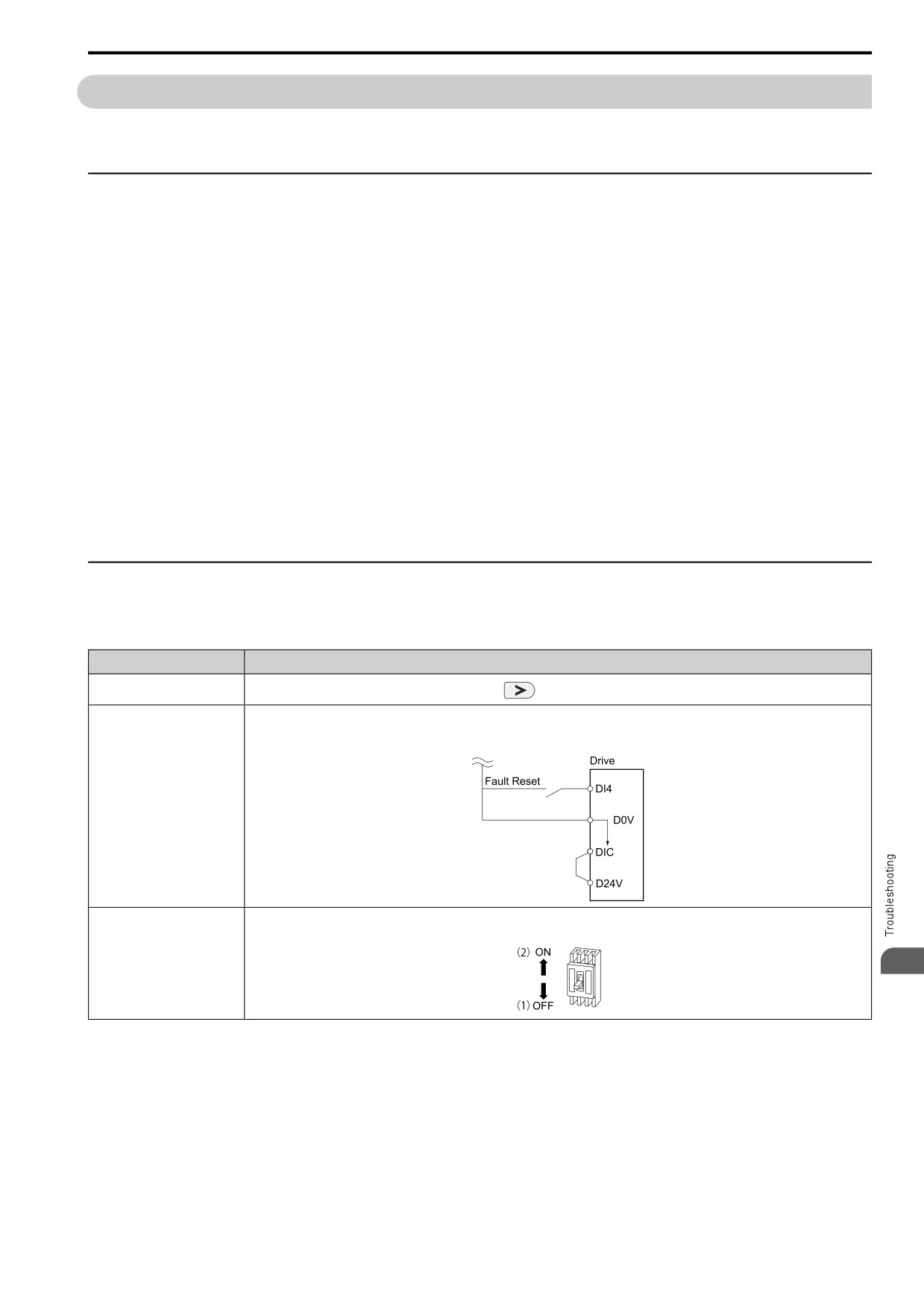
7.9 Diagnosing and Resetting Faults
7.9
Diagnosing and Resetting Faults
When a fault occurs and the drive stops, do the procedures in this section to remove the cause of the fault, then re-
energize the drive.
◆ Fault Occurs Without Power Loss
WARNING! Crush Hazard. Wear eye protection when you do work on the drive. If you do not use correct safety equipment, it
can cause serious injury or death.
WARNING! Electrical Shock Hazard. After the drive blows a fuse or trips an RCM/RCD, do not immediately energize the drive
or operate peripheral devices. Wait for the time specified on the warning label at a minimum and make sure that all indicators
are OFF. Then check the wiring and peripheral device ratings to find the cause of the problem. If you do not know the cause of
the problem, contact the manufacturer before you energize the drive or peripheral devices. If you do not fix the problem before
you operate the drive or peripheral devices, it can cause serious injury or death.
1. Supply power to the control circuit from the external 24 V input.
2. Examine the fault code shown on the keypad.
3. Use monitor parameters [U2: FAULT] to show the fault code and data about the operating status of the
drive immediately before the fault occurred.
4. Use the information in the Troubleshooting tables to remove the fault.
5. Do a fault reset.
Note:
1. To find the faults that were triggered, check the fault history in U2-02 [Previous Fault]. To find information about drive status (such
as frequency, current, and voltage) when the faults were triggered, check U2-03 to U2-20.
2. If the fault display stays after you re-energize the drive, remove the cause of the fault and reset.
◆ Fault Reset Procedure
If a fault occurs, you must remove the cause of the fault and re-energize the drive.
Table 7.3 Fault Reset Methods
Methods
Description
Method 1
While the keypad is showing the fault or alarm code, push
on the keypad.
Switch ON the MFDI terminal set to H1-xx = 7B [MFDI Function Select = Fault Reset].
Note:
The default setting for H1-04 [DI4 Function Selection] is 7B [Fault Reset].
Method 2
1.
De-energize the drive main circuit power supply.
2.
Energize the drive again after the keypad display goes out.
Method 3
7
Note:
If the drive receives a Run command from a communication option or control circuit terminal, the drive will not reset the fault. Turn the
Run command OFF to reset the fault. If you do a fault reset when the drive has a Run command, the keypad will show minor fault CrST
[Remove RUN Command to Reset].
257
7.10 Troubleshooting Without Fault Display
7.10
Troubleshooting Without Fault Display
If the drive or motor operate incorrectly, but the keypad does not show a fault or error code, refer to the items this
section.
• Motor hunting and oscillation
• Unsatisfactory motor torque
• Unsatisfactory speed precision
• Unsatisfactory motor torque and speed response
• Motor noise
◆ Typical Problems
Symptom
Reference
The Parameter Settings Will Not Change
258
The Motor Does Not Rotate After Entering Run Command
259
The Motor Rotates in the Opposite Direction from the Run Command
260
The Motor Rotates in Only One Direction
260
The Motor Is Too Hot
260
The Correct Auto-Tuning Mode Is Not Available
261
The Motor Stalls during Acceleration or Accel/Decel Time Is Too Long
261
The Drive Frequency Reference Is Different than the Controller Frequency Reference Command
262
The Motor Speed Is Not Stable When Using a PM Motor
262
There Is Too Much Motor Oscillation and the Rotation Is Irregular
262
Deceleration Takes Longer Than Expected When Dynamic Braking Is Enabled
262
The Load Falls When a Brake Is Applied
263
There Is Audible Noise from the Drive or Motor Cables When the Drive Is Energized
263
Residual Current Monitoring/Detection (RCM/RCD) Trips During Run
263
Motor Rotation Causes Unexpected Audible Noise from Connected Machinery
263
Motor Rotation Causes Oscillation or Hunting
263
PID Output Fault
264
The Starting Torque Is Not Sufficient
264
The Motor Rotates after the Drive Output Is Shut Off
264
The Output Frequency Is Lower Than the Frequency Reference
264
The Motor Is Making an Audible Noise
264
The Motor Will Not Restart after a Loss of Power
265
◆ The Parameter Settings Will Not Change
Causes
Possible Solutions
The drive is operating the motor (the drive is in Drive Mode).
Stop the drive and change to Programming Mode.
Parameter A1-01 = 0 [Access Level = Monitor only].
Set A1-01 = 2 [Access Level = Standard Parameters] or A1-01 = 3
[Expert Parameters].
Parameter H1-xx = 7C [MFDI Function Select = Prg Lock].
Turn ON the terminals to which H1-xx = 7C is set, and then change the parameters.
258
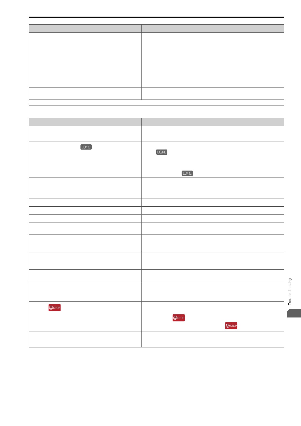
7.10 Troubleshooting Without Fault Display
Causes
Possible Solutions
An incorrect password was entered in A1-04 [Password Input].
• Enter the correct password to A1-04 again.
• If you forgot the password, set the password again with A1-04 and A1-05 [Password Setting].
Note:
If the password is set, it will not be possible to change these parameters until the password
matches:
• A1-01 [Access Level]
• A1-02 [Control Method]
• A1-03 [Init Parameters]
• A1-06 [Macro Preset]
• A1-07 [Q2pack Enable]
• A2-01 to A2-32 [MAN1 Param1 to MAN3 Param12]
The drive detected Uv [Undervoltage].
• View U1-07 [DC Bus Voltage] to see the power supply voltage.
• Examine the main circuit wiring.
◆ The Motor Does Not Rotate After Entering Run Command
Causes
Possible Solutions
The drive is not in Drive Mode.
1.
Make sure that the READY LED on the keypad is on.
2.
If the READY LED is off, push and hold the ESC Key to go back to the frequency reference
screen (the initial screen).
Do one of these two:
The drive stopped and you pushed
to transfer the Run command
source to the keypad.
• Push
• Re-energize the drive.
Note:
Set o2-01 = 0 [LO/RE Key Selection of Function = Disabled] to prevent changing the Run
command source with
Auto-Tuning completed.
Push and hold the ESC Key to go back to the frequency reference screen (the initial screen).
Note:
When Auto-Tuning completes, the drive changes to Programming Mode. The drive will not
accept a Run command unless the drive is in Drive Mode.
The drive received a Fast Stop command.
Turn off the fast stop input signal.
The settings for the source that supplies the Run command are incorrect.
Set b1-02 [Run Comm. Sel 1] correctly.
The frequency reference source is set incorrectly.
Set b1-01 [Freq. Ref. Sel. 1] correctly.
There is defective wiring in the control circuit terminals.
• Correctly wire the drive control circuit terminals.
• View U1-10 [In Terminal Status] for input terminal status.
The settings for voltage input and current input of the master frequency
Examine these analog input terminal signal level settings:
reference are incorrect.
• Terminal AI1: H3-01 [AI1 Signal Level Select]
• Terminal AI2: DIP switch S1 and H3-09 [AI2 Signal Level Select]
The selection for the sinking/sourcing mode and the internal/external power
• For sinking mode, close the circuit between terminals DIC-D24V with a wire jumper.
supply is incorrect.
• For sourcing mode, close the circuit between terminals DIC-D0V with a wire jumper.
• For external power supply, remove the wire jumper.
The frequency reference is too low.
• View U1-01 [Frequency Reference].
• Increase the frequency reference to a value higher than E1-09 [Min Output Frequency].
The MFAI setting is incorrect.
• Make sure that the functions set to the MFAI are correct. The frequency reference is 0 when
H3-02, H3-10 = 5 [MFAI Function Select = Freq Gain] and voltage (current) is not input.
• Use U1-13, U1-14 [Terminal AI1 InputLv, Terminal AI2 InputLv] to make sure that the analog
input values set to terminals AI1 and AI2 are applicable.
Turn the Run command OFF then ON from an external input.
You pushed
Note:
7
When you push
during operation, the drive will ramp to stop. Set o2-02 = 0 [STOP
Key Selection of Function = Disabled] to disable the
function.
The 2-wire sequence and 3-wire sequence are set incorrectly.
• Set one of the parameters H1-03 to H1-07 [DI3 Function Selection to DI7 Function Selection]
to 5 [3-Wire Seq.] to enable the 3-wire sequence.
• If a 2-wire sequence is necessary, make sure that H1-03 to H1-07 ≠ 5.
259
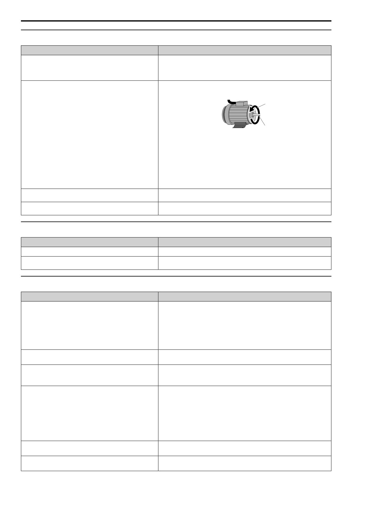
7.10 Troubleshooting Without Fault Display
◆ The Motor Rotates in the Opposite Direction from the Run Command
Causes
Possible Solutions
The phase wiring between the drive and motor is incorrect.
• Examine the wiring between the drive and motor.
• Connect drive output terminals U/T1, V/T2, and W/T3 in the correct sequence to agree with
motor terminals U, V, and W.
• Switch two motor cables U, V, and W to reverse motor direction.
The forward direction for the motor is set incorrectly.
• Connect drive output terminals U/T1, V/T2, and W/T3 in the correct sequence to agree with
motor terminals U, V, and W.
• Switch two motor cables U, V, and W to reverse motor direction.
A
B
A - Forward Rotation
B - Load Shaft
Direction
Figure 7.1 Forward Rotating Motor
Note:
• For Yaskawa motors, the forward direction is counterclockwise when looking from the
motor shaft side.
• Refer to the motor specifications, and make sure that the forward rotation direction is
correct for the application. The forward rotation direction of motors can be different for
different motor manufacturers and types.
The signal connections for forward run and reverse run on the drive control
Correctly wire the control circuit.
circuit terminals and control panel side are incorrect.
The motor is running at almost 0 Hz and the Speed Search estimated the
Set b3-14 = 0 [Speed Bi-Directional Search = Disabled], then the drive will only do speed search
speed to be in the opposite direction.
in the specified direction.
◆ The Motor Rotates in Only One Direction
Causes
Possible Solutions
The drive will not let the motor rotate in reverse.
Set b1-04 = 0 [Reverse Operation Selection = Enabled].
The drive did not receive a Reverse run signal and 3-Wire sequence is
Turn ON the terminals to which H1-xx = 5 [3-Wire Seq.] is set, and then enable reverse
selected.
operation.
◆ The Motor Is Too Hot
Causes
Possible Solutions
The load is too heavy.
• Decrease the load.
• Increase the acceleration and deceleration times.
• Examine the values set in L1-01 [Motor Cool Type for OL1 Calc], L1-02 [OL1 Protect Time],
and E2-01 [Mot Rated Current (FLA)].
• Use a larger motor.
Note:
The motor also has a short-term overload rating. Examine this rating carefully before setting
drive parameters.
The motor is running continuously at a very low speed.
• Change the run speed.
• Use a drive-dedicated motor.
The drive is operating in a vector control mode, but Auto-Tuning has not
• Do Auto-Tuning.
been done.
• Calculate motor parameter and set motor parameters.
• Set A1-02 = 0 [Control Method = V/f Control].
The voltage insulation between motor phases is not sufficient.
• Use a motor with a voltage tolerance that is higher than the maximum voltage surge.
• Use a drive-dedicated motor that is rated for use with AC drives for applications that use a
motor on drives rated higher than 400 V class.
• Install an AC reactor on the output side of the drive and set C6-02 = 1 [Carrier Frequency
Selection = 2.0 kHz].
Note:
When the motor is connected to the drive output terminals U/T1, V/T2, and W/T3, surges
occur between the drive switching and the motor coils. These surges can be three times the
drive input power supply voltage (600 V for a 200 V class drive, 1200 V for a 400 V class
drive).
The air around the motor is too hot.
• Measure the ambient temperature.
• Decrease the temperature in the area until it is in the specified temperature range.
The motor fan stopped or is clogged.
• Clean the motor fan.
• Make the drive environment better.
260
7.10 Troubleshooting Without Fault Display
◆ The Correct Auto-Tuning Mode Is Not Available
Causes
Possible Solutions
The desired Auto-Tuning mode is not available for the selected control
Change the motor control method with parameter A1-02 [Control Method].
mode.
◆ The Motor Stalls during Acceleration or Accel/Decel Time Is Too Long
Causes
Possible Solutions
The drive and motor system are at the torque limit or current suppression
• Decrease the load.
will not let the drive accelerate.
• Use a larger motor.
Note:
Although the drive has a Stall Prevention function and a Torque Compensation Limit
function, if you try to accelerate too fast or try to drive a load that is too large, it can be too
much for the limits of the motor.
Torque limit is set incorrectly.
Set the torque limit correctly.
The acceleration time setting is too short.
Examine the values set in C1-01, C1-03, C1-05, or C1-07 [Acceleration Time] and set them to
applicable values.
The load is too large.
• Increase the acceleration time.
• Examine the mechanical brake and make sure that it is fully releasing.
• Decrease the load to make sure that the output current stays less than the motor rated current.
• Use a larger motor.
Note:
• In extruder and mixer applications, the load can increase as the temperature decreases.
• Although the drive has a Stall Prevention function and a Torque Compensation Limit
function, if you try to accelerate too fast or try to drive a load that is too large, it can be too
much for the limits of the motor.
The frequency reference is low.
• Examine E1-04 [Max Output Frequency] and increase the setting if it is set too low.
• Examine U1-01 [Frequency Reference] for the correct frequency reference.
• Examine the multi-function input terminals to see if a frequency reference signal switch is set.
• When you use an MFAI, examine the low gain level set in H3-03, H3-11 [AI1 Gain Setting,
AI2 Gain Setting].
The frequency reference is set incorrectly.
When H3-10 = 5 [AI2 Function Selection = Freq Gain], see if the drive is set for voltage
(current).
• Examine the value set in H3-10.
• Use U1-14 [Terminal AI2 InputLv] to make sure that the analog input value set to terminal
AI2 is applicable.
The motor characteristics and drive parameter settings are not compatible.
• Set the correct V/f pattern to agree with the characteristics of the motor.
• Examine the V/f pattern set in E1-03 [V/f Pattern Selection].
• Do Rotational Auto-Tuning.
The drive is operating in vector control mode, but you did not complete
• Do Auto-Tuning.
Auto-Tuning.
• Calculate motor data and reset motor parameters.
• Set A1-02 = 0 [Control Method = V/f Control].
The Stall Prevention level during acceleration setting is too low.
Increase the value set in L3-02 [StallP Level@Accel].
Note:
If the L3-02 value is too low, the acceleration time can be unsatisfactorily long.
The Stall Prevention level during run setting is too low.
Increase the value set in L3-06 [StallP Level@Run].
Note:
If the L3-06 value is too low, speed will decrease before the drive outputs torque.
The drive is at the limit of the V/f motor control method.
• When the motor cable is longer than 50 m (164 ft), do Auto-Tuning for line-to-line resistance.
• Set the V/f pattern to “High Starting Torque”.
• Use a Vector Control method.
Note:
7
V/f control method does not supply high torque at low speeds.
261
7.10 Troubleshooting Without Fault Display
◆ The Drive Frequency Reference Is Different than the Controller Frequency
Reference Command
Causes
Possible Solutions
The analog input gain and bias for the frequency reference input are set
Examine the gain and bias settings for the analog inputs that set the frequency reference.
incorrectly.
• Terminal AI1: H3-03 [AI1 Gain Setting], H3-04 [AI1 Bias Setting]
• Terminal AI2: H3-11 [AI2 Gain Setting], H3-12 [AI2 Bias Setting]
The drive is receiving frequency bias signals from analog input terminals
• Examine parameters H3-02, H3-10 [MFAI Function Select]. If both of these parameters = 4
AI1 and AI2 and the sum of all signals makes the frequency reference.
[Freq Ref/BIAS], change the settings.
• Use U1-13, U1-14 [Terminal AI1 InputLv, Terminal AI2 InputLv] to make sure that the analog
input values set to terminals AI1 and AI2 are applicable.
PID control is enabled.
If PID control is not necessary, set b5-01 = 0 [PID Enable = Disabled].
Note:
When PID control is enabled, the drive adjusts the output frequency as specified by the target
value. The drive will only accelerate to the maximum output frequency set in E1-04 [Max
Output Frequency] while PID control is active.
◆ The Motor Speed Is Not Stable When Using a PM Motor
Causes
Possible Solutions
E5-01 [PM Mot Code Selection] is set incorrectly.
Refer to “Motor Performance Fine-Tuning” in the technical manual.
The drive is operating the motor at more than the specified speed control
Examine the speed control range and adjust the speed.
range.
The motor is hunting.
Adjust these parameters to have the largest effect:
• n8-55 [Load Inertia]
• n8-45 [SpdFbck Det.Gain]
• C4-02 [Trq Comp Delay Time]
Hunting occurs at start.
Increase the value set in C2-01 [Jerk@Start of Accel].
Too much current is flowing through the drive.
Set E5-01 [PM Mot Code Selection] correctly as specified by the motor. For special-purpose
motors, enter the correct value to E5-xx as specified by the motor test report.
Operation is not stable when n8-57 = 1 [High-Freq Injection = Enabled].
• Do High Frequency Injection Auto-Tuning.
• Decrease the value set in n8-41 [HFI PoleDet Pgain] in increments of 0.5.
Note:
Set n8-41 > 0.0 for IPM motors.
◆ There Is Too Much Motor Oscillation and the Rotation Is Irregular
Causes
Possible Solutions
Unsatisfactory balance of motor phases.
• Make sure that the drive input power voltage supplies stable power.
• Set L8-05 = 0 [In PhaseLoss Selection = Disabled].
The motor is hunting.
• Set n1-01 = 1 [HuntPrev Selection = Enabled].
• Increase the value of n2-01 [AFR Gain] or n2-02 [AFR Time 1].
◆ Deceleration Takes Longer Than Expected When Dynamic Braking Is Enabled
Causes
Possible Solutions
The stall prevention during deceleration setting is incorrect.
• Examine the setting for L3-04 [StallP@Decel Enable].
• When the drive has a dynamic braking option installed, set L3-04 = 0 [Disabled].
• If the drive detects ov [Overvoltage], set L3-04 = 1 [Enabled] and L3-50 = 2 [StallP@Decel
Mode = Gen Purpose w/ DB Resistor].
The deceleration time setting is too long.
Set C1-02, C1-04, C1-06, or C1-08 [Deceleration Times] to applicable values.
The motor torque is not sufficient.
Use a larger motor.
Note:
If these items are correct, the demand on the motor is more than the motor capacity:
• Parameter settings are correct.
• The drive does not detect ov [Overvoltage].
262
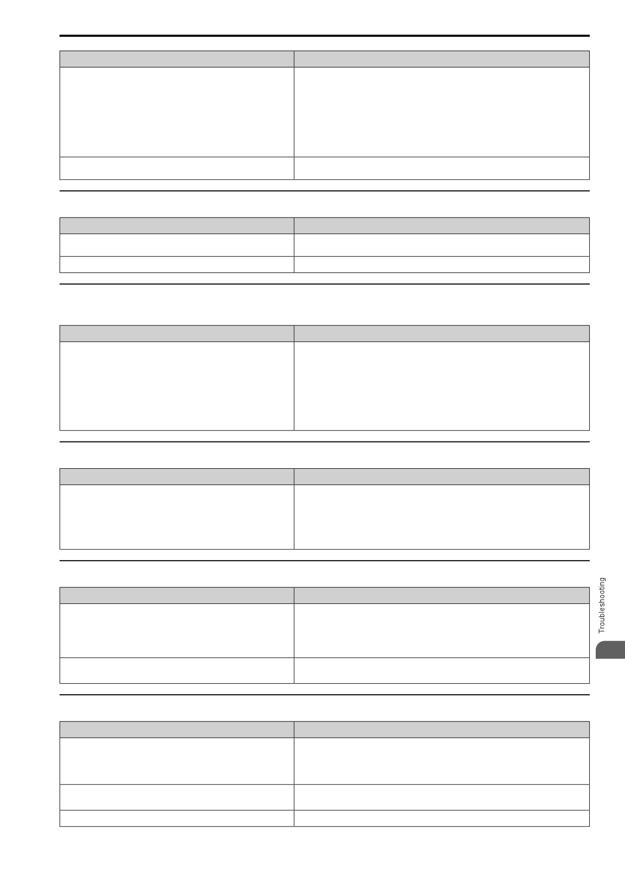
7.10 Troubleshooting Without Fault Display
Causes
Possible Solutions
The drive and motor system reached the torque limit.
• Examine the values set in L7-01 to L7-04 [Torque Limit] and increase them if necessary.
Note:
If the torque limit is enabled, deceleration time can increase because the drive cannot output
more torque than the limit.
• If H3-02, H3-10 = 9, B, C, D [MFAI Function Select = Torque Limit], examine the settings for
the MFAIs.
• Examine the values set in H3-02 and H3-10.
• Use U1-13, U1-14 [Terminal AI1 InputLv, Terminal AI2 InputLv] to make sure that the
analog input values set to terminals A1 and A2 are applicable.
The load is more than the internal torque limit as specified by the drive rated
Replace the drive with a larger capacity model.
current.
◆ The Load Falls When a Brake Is Applied
Causes
Possible Solutions
The open/close timing of the brake is incorrect.
Refer to “Notes on Controlling the Brake when Using the Hoist Application Preset” in the
technical manual and take appropriate measures.
The DC injection braking is not sufficient.
Increase the value set in b2-02 [DCI Braking Current].
◆ There Is Audible Noise from the Drive or Motor Cables When the Drive Is
Energized
Causes
Possible Solutions
The relay switching in the drive is making too much noise.
• Use C6-02 [Carrier Frequency Selection] to decrease the carrier frequency.
• Connect a noise filter to the input side of the drive power supply.
• Connect a noise filter to the output side of the drive.
• Isolate the control circuit wiring from the main circuit wiring.
• Use a metal cable gland to wire the drive.
• Shield the periphery of the drive with metal.
• Make sure that the drive and motor are grounded correctly.
• Make sure that ground faults have not occurred in the wiring or motor.
◆ Residual Current Monitoring/Detection (RCM/RCD) Trips During Run
Causes
Possible Solutions
There is too much leakage current from the drive.
• Increase the RCM/RCD sensitivity or use RCM/RCD with a higher threshold.
• Use C6-02 [Carrier Frequency Selection] to decrease the carrier frequency.
• Decrease the length of the cable used between the drive and the motor.
• Install a noise filter or AC reactor on the output side of the drive. Set C6-02 = 1 [2.0 kHz]
when connecting an AC reactor.
• Disable the internal EMC filter.
◆ Motor Rotation Causes Unexpected Audible Noise from Connected Machinery
Causes
Possible Solutions
The carrier frequency and the resonant frequency of the connected
• Adjust C6-02 to C6-05 [Carrier Frequency].
machinery are the same.
• Set C6-02 = 1 to 6 [Carrier Frequency Selection = Frequency other than Swing PWM].
Note:
If C6-02 = 7 to A [Carrier Frequency Selection = Swing PWM], the drive will not know if
the noise comes from the drive or the machine.
7
The drive output frequency and the resonant frequency of the connected
• Adjust d3-01 to d3-04 [Jump Frequency 1 to Jump Frequency Width].
machinery are the same.
• Put the motor on a rubber pad to decrease vibration.
◆ Motor Rotation Causes Oscillation or Hunting
Causes
Possible Solutions
The frequency reference is assigned to an external source, and there is
Make sure that electrical interference does not have an effect on the signal lines.
electrical interference in the signal.
• Isolate control circuit wiring from main circuit wiring.
• Use twisted-pair cables or shielded wiring for the control circuit.
• Increase the value of H3-13 [An.In FilterTime Constant].
The cable between the drive and motor is too long.
• Do Auto-Tuning.
• Make the wiring as short as possible.
The PID parameters are not sufficiently adjusted.
Adjust [b5: PID CONTROL].
263
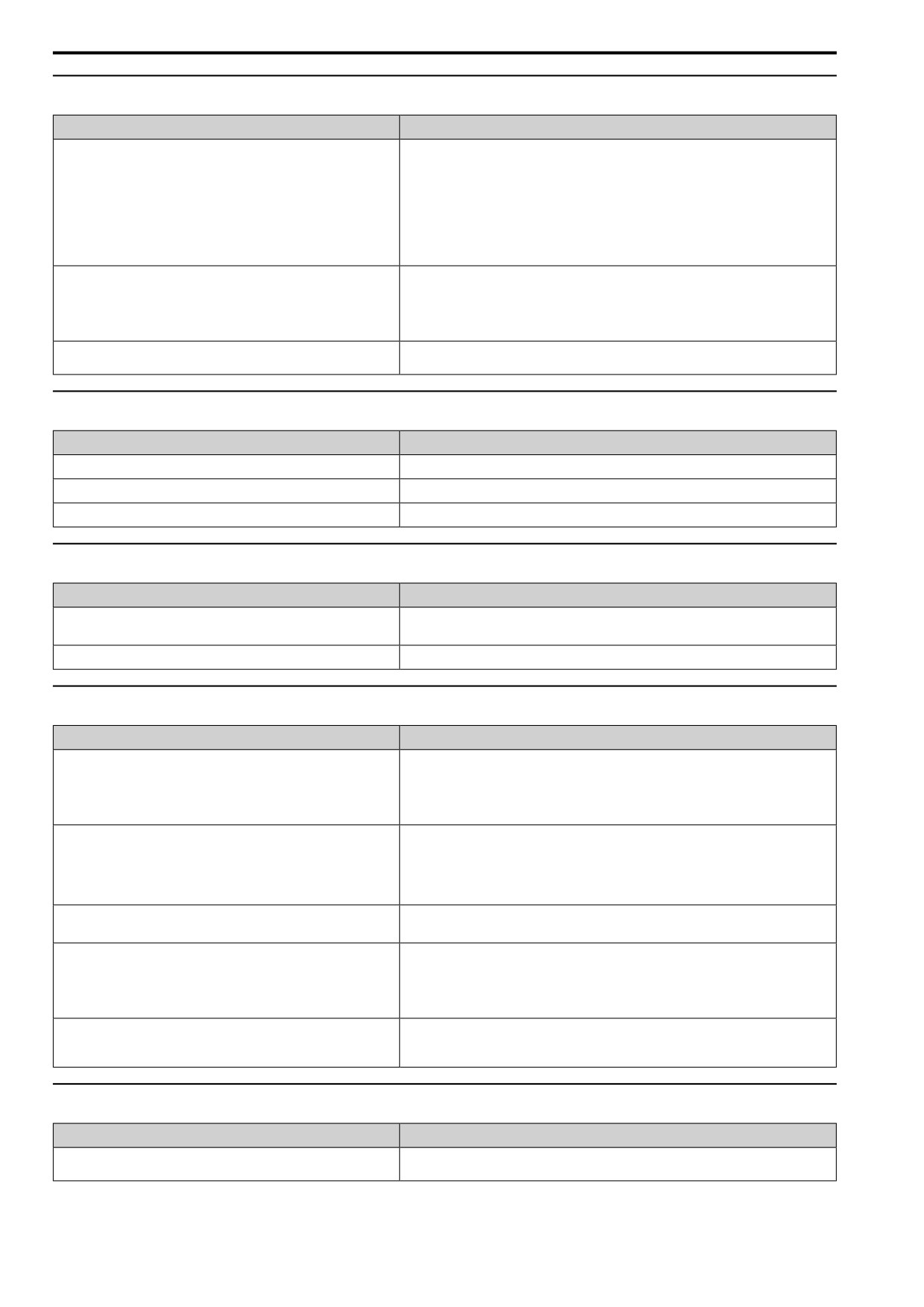
7.10 Troubleshooting Without Fault Display
◆ PID Output Fault
Causes
Possible Solutions
There is no PID feedback input.
• Examine the MFAI terminal settings.
• Make sure that H3-02, H3-10 = F [MFAI Function Select = PID Fbk].
• Make sure that the MFAI terminal settings agree with the signal inputs.
• Examine the connection of the feedback signal.
• Make sure that [b5: PID CONTROL] is set correctly.
Note:
If there is no PID feedback input to the terminal, the detected value is 0, which causes a PID
fault and also causes the drive to operate at maximum frequency.
The detection level and the target value do not agree.
Use H3-03, H3-11 [AI1 Gain Setting, AI2 Gain Setting] to adjust PID target and feedback signal
scaling.
Note:
PID control keeps the difference between the target value and detection value at 0. Set the
input level for the values relative to each other.
Reverse drive output frequency and speed detection. When output frequency
Set b5-09 = 1 [PID Output Level Selection = Reverse output].
increases, the sensor detects a speed decrease.
◆ The Starting Torque Is Not Sufficient
Causes
Possible Solutions
Auto-Tuning has not been done in vector control method.
Do Auto-Tuning.
The control method was changed after doing Auto-Tuning.
Do Auto-Tuning again.
Stationary Auto-Tuning for Line-to-Line Resistance was done.
Do Rotational Auto-Tuning.
◆ The Motor Rotates after the Drive Output Is Shut Off
Causes
Possible Solutions
DC Injection Braking is too low and the drive cannot decelerate correctly.
• Increase the value set in b2-02 [DCI Braking Current].
• Increase the value set in b2-04 [DCInj Time@Stop].
The stopping method makes the drive coast to stop.
Set b1-03 = 0 or 2 [Stopping Method Selection = Ramp->Stop, DC Inj->Stop].
◆ The Output Frequency Is Lower Than the Frequency Reference
Causes
Possible Solutions
The frequency reference is in the Jump frequency range.
Adjust d3-01 to d3-03 [Jump Frequency 1 to Jump Frequency 3] and d3-04 [Jump Frequency
Width].
Note:
Enabling the Jump frequency prevents the drive from outputting the frequencies specified in
the Jump range.
The upper limit for the frequency reference has been exceeded.
Set E1-04 [Max Output Frequency] and d2-01 [FRef Upper Limit] to the best values for the
application.
Note:
This calculation supplies the upper value for the output frequency:
E1-04 × d2-01 / 100
A large load triggered Stall Prevention function during acceleration.
• Decrease the load.
• Adjust L3-02 [StallP Level@Accel].
L3-01 = 4 [StallP Mode@Accel = ILim Mode] has been set.
1.
Check whether the V/f pattern and motor parameter settings are appropriate, and set them
correctly.
2.
If this does not solve the problem, and it is not necessary to limit the current level of stall
during acceleration, adjust L3-02.
3.
If this does not solve the problem, set L3-01 = 2 [General Purpose].
The motor is rotating at this speed:
Set E1-09 < b2-01.
b2-01 [ZSpd/DCI Threshold] ≤ Motor Speed < E1-09 [Min Output
Frequency]
◆ The Motor Is Making an Audible Noise
Causes
Possible Solutions
100% of the rated output current of the drive was exceeded while operating
If the sound is coming from the motor, set L8-38 = 0 [Carrier Reduction Mode = Disabled].
at low speeds.
264
7.10 Troubleshooting Without Fault Display
◆ The Motor Will Not Restart after a Loss of Power
Causes
Possible Solutions
The drive did not receive a Run command after applying power.
• Examine the sequence and wiring that enters the Run command.
• Set up a relay to make sure that the Run command stays enabled during a loss of power.
For applications that use 3-wire sequence, the momentary power loss
Examine the wiring and circuitry for the relay that keeps the Run command enabled during the
continued for a long time, and the relay that keeps the Run command has
momentary power loss ride-thru time.
been switched off.
7
265
7.10 Troubleshooting Without Fault Display
266
8
Periodic Inspection and Maintenance
This chapter gives information about how to examine and maintain drives in use, how to replace
cooling fans and other parts, and how to store drives.
8.1
Safety Precautions
268
8.2
Inspection
270
8.3
Maintenance
272
8.4
Replace Cooling Fans
274
8.5
Replace the Drive
279
8.6
Storage Guidelines
283
267
8.1 Safety Precautions
8.1
Safety Precautions
DANGER
Electrical Shock Hazard
Do not examine, connect, or disconnect wiring on an energized drive. Before servicing,
disconnect all power to the equipment and wait for the time specified on the warning label at a
minimum. The internal capacitor stays charged after the drive is de-energized. The charge
indicator LED extinguishes when the DC bus voltage decreases below 50 Vdc. When all
indicators are OFF, measure for dangerous voltages to make sure that the drive is safe.
If you do work on the drive when it is energized, it will cause serious injury or death from electrical shock. The
drive has internal capacitors that stay charged after you de-energize the drive.
Disconnect all power to the drive and wait for the time specified on the warning label before you
remove covers. Check the drive for dangerous voltages before servicing or repair work.
If you do work on the drive when it is energized and there is no cover over the electronic circuits, it will cause
serious injury or death from electrical shock. The drive has internal capacitors that stay charged after you de-
energize the drive.
WARNING
Electrical Shock Hazard
The motor will run after you de-energize the drive. PM motors can generate induced voltage to
the terminal of the motor after you de-energize the drive.
If you touch a motor that is moving or energized, it can cause serious injury or death.
Do not operate the drive when covers are missing. Replace covers and shields before you
operate the drive. Use the drive only as specified by the instructions.
Some figures in this section include drives without covers or safety shields to more clearly show the inside of the
drive. If covers or safety shields are missing from the drive, it can cause serous injury or death.
Always ground the motor-side grounding terminal.
If you do not ground the equipment correctly, it can cause serious injury or death if you touch the motor case.
Only let approved personnel install, wire, maintain, examine, replace parts, and repair the drive.
If personnel are not approved, it can cause serious injury or death.
Do not wear loose clothing or jewelry when you do work on the drive. Tighten loose clothing
and remove all metal objects, for example watches or rings.
Loose clothing can catch on the drive and jewelry can conduct electricity and cause serious injury or death.
Fire Hazard
Tighten all terminal screws to the correct tightening torque.
Connections that are too loose or too tight can cause incorrect operation and damage to the drive. Incorrect
connections can also cause death or serious injury from fire.
Do not use the main circuit power supply (Overvoltage Category III) at incorrect voltages.
Operate the drive in the specification range of the input voltage on the drive nameplate.
Voltages that are higher than the permitted nameplate tolerance can cause damage to the drive.
Do not put flammable or combustible materials on top of the drive and do not install the drive
near flammable or combustible materials. Attach the drive to metal or other noncombustible
material.
Flammable and combustible materials can start a fire and cause serious injury or death.
268
8.1 Safety Precautions
WARNING
Electrical Shock Hazard
Do not modify the drive body or drive circuitry.
Modifications to drive body and circuitry can cause serious injury or death, will cause damage to the drive, and
will void the warranty. The manufacturer is not responsible for modifications of the product made by the user.
Sudden Movement Hazard
Make sure that you align the phase order for the drive and motor when you connect the motor to
drive output terminals U/T1, V/T2, and W/T3.
If the phase order is incorrect, it can cause the motor to run in reverse. If the motor accidentally runs in reverse, it
can cause serious injury or death.
CAUTION
Burn Hazard
Do not touch a hot drive heatsink. De-energize the drive, wait for a minimum of 15 minutes, then
make sure that the heatsink is cool before you replace the cooling fans.
If you touch a hot drive heatsink, it can burn you.
NOTICE
Obey correct electrostatic discharge (ESD) procedures when you touch the drive.
Incorrect ESD procedures can cause damage to the drive circuitry.
Use the instructions in this manual to replace the cooling fans. When you do maintenance on
the fans, replace all the fans to increase product life.
If you install the fans incorrectly, it can cause damage to the drive.
Make sure that all connections are correct after you install the drive and connect peripheral
devices.
Incorrect connections can cause damage to the drive.
The drive can fail if users frequently turn the drive ON and OFF with the MC on the power source
side to Run and Stop the drive. Incorrect operation can decrease the service life of the relay
contacts and electrolytic capacitors.
If you frequently use the magnetic contactor on the power source side to Run and Stop the drive, it can cause
drive failure.
Do not operate a drive or connected equipment that has damaged or missing parts.
You can cause damage to the drive and connected equipment.
Note:
Do not use unshielded cable for control wiring. Use shielded, twisted-pair wires and ground the shield to the ground terminal of the
drive. Unshielded wire can cause electrical interference and unsatisfactory system performance.
8
269
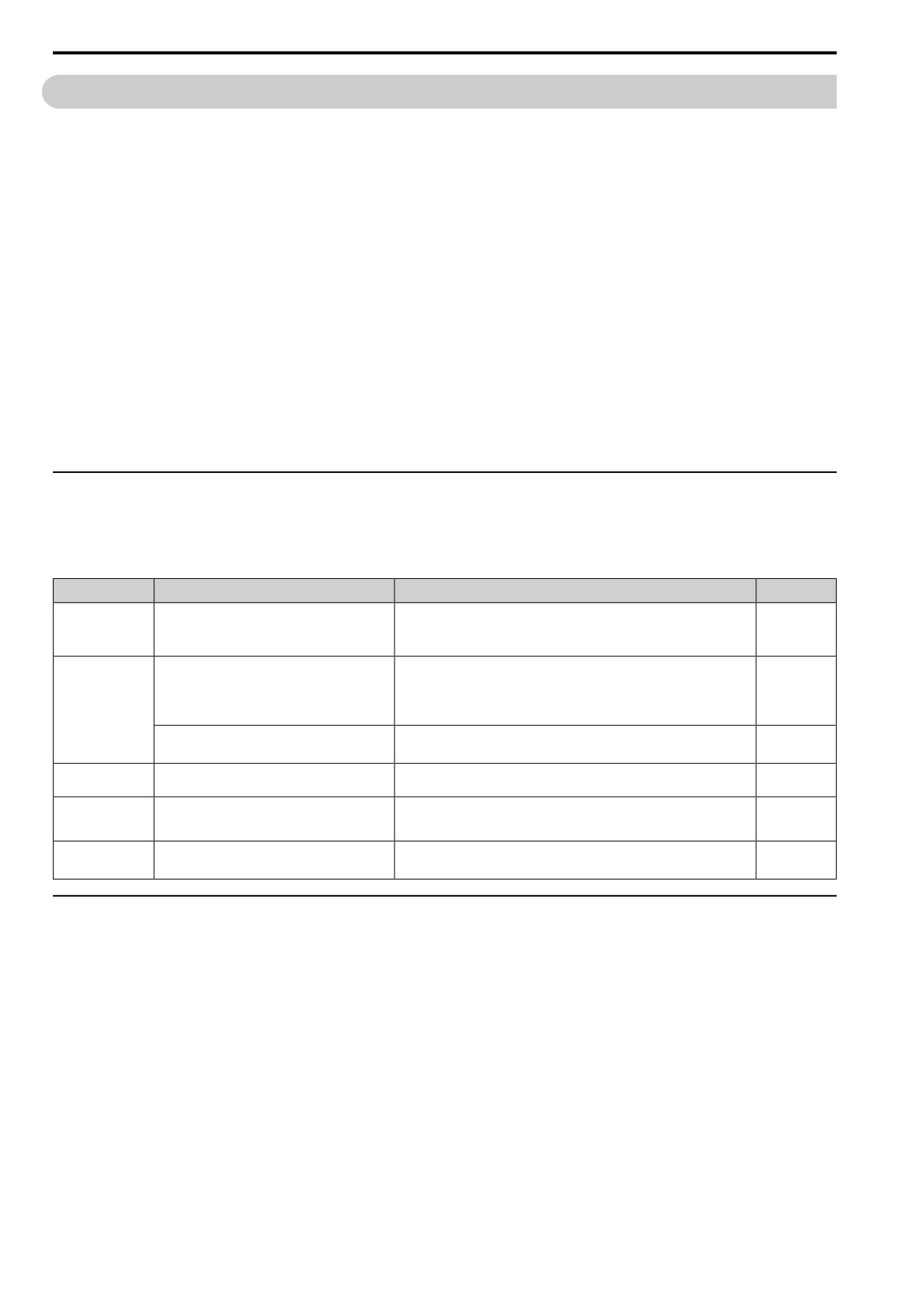
8.2 Inspection
8.2
Inspection
Power electronics have limited life and can show changes in performance and deterioration of performance after
years of use in usual conditions. To help prevent these problems, it is important to do preventive maintenance and
regular inspection, and replace parts on the drive.
Drives contain different types of power electronics, for example power transistors, semiconductors, capacitors,
resistors, fans, and relays. The electronics in the drive are necessary for correct motor control.
Follow the inspection lists in this chapter as a part of a regular maintenance program.
Note:
Examine the drive one time each year at a minimum.
The operating conditions, environmental conditions, and use conditions will have an effect on the examination frequency for connected
equipment.
Examine the drive more frequently if you use the drive in bad conditions or in these conditions:
• High ambient temperatures
• Frequent starting and stopping
• Changes in the AC power supply or load
• Too much vibration or shock loading
• Dust, metal dust, salt, sulfuric acid, or chlorine atmospheres
• Unsatisfactory storage conditions.
◆ Recommended Daily Inspection
Examine the following items each day to make sure that the components do not wear out or fail. Make a copy of
this checklist and put a check mark in the “Checked” column after each inspection.
Table 8.1 Daily Inspection Checklist
Inspection Area
Inspection Points
Corrective Action
Checked
• Check the load coupling.
Examine for unusual oscillation or noise coming
Motor
• Measure motor vibration.
from the motor.
• Tighten all loose components.
• Check for a load that is too heavy.
Examine for unusual heat from the drive or motor
• Tighten loose screws.
and visible discoloration.
• Check for a dirty heatsink or motor.
Cooling System
• Measure the ambient temperature.
• Check for a clogged or dirty fan.
Examine the cooling fans.
• Use the performance life monitor to check for correct fan operation.
Surrounding
Make sure that the installation environment is
Remove the source of contamination or correct unsatisfactory environment.
Environment
applicable.
Make sure that the drive output current is not more
• Check for a load that is too heavy.
Load
than the motor or drive rating for an extended period
of time.
• Check the correct motor parameter settings.
Power Supply
• Correct the voltage or power supply to agree with nameplate specifications.
Examine main power supply and control voltages.
Voltage
• Verify all main circuit phases.
◆ Recommended Periodic Inspection
The following tables give information about the recommended periodic inspections for AC drives. Examine the
drive one time each year at a minimum. The operating conditions, environmental conditions, and use conditions
will have an effect on the examination frequency for connected equipment. You must use your experience with the
application to select the correct inspection frequency for each drive installation. Periodic inspections will help to
prevent performance deterioration and product failure. Make a copy of this checklist and put a check mark in the
“Checked” column after each inspection.
DANGER! Electrical Shock Hazard. Do not examine, connect, or disconnect wiring on an energized drive. Before servicing,
disconnect all power to the equipment and wait for the time specified on the warning label at a minimum. The internal capacitor
stays charged after the drive is de-energized. The charge indicator LED extinguishes when the DC bus voltage decreases
below 50 Vdc. When all indicators are OFF, measure for dangerous voltages to make sure that the drive is safe. If you do work
on the drive when it is energized, it will cause serious injury or death from electrical shock. The drive has internal capacitors that
stay charged after you de-energize the drive.
270
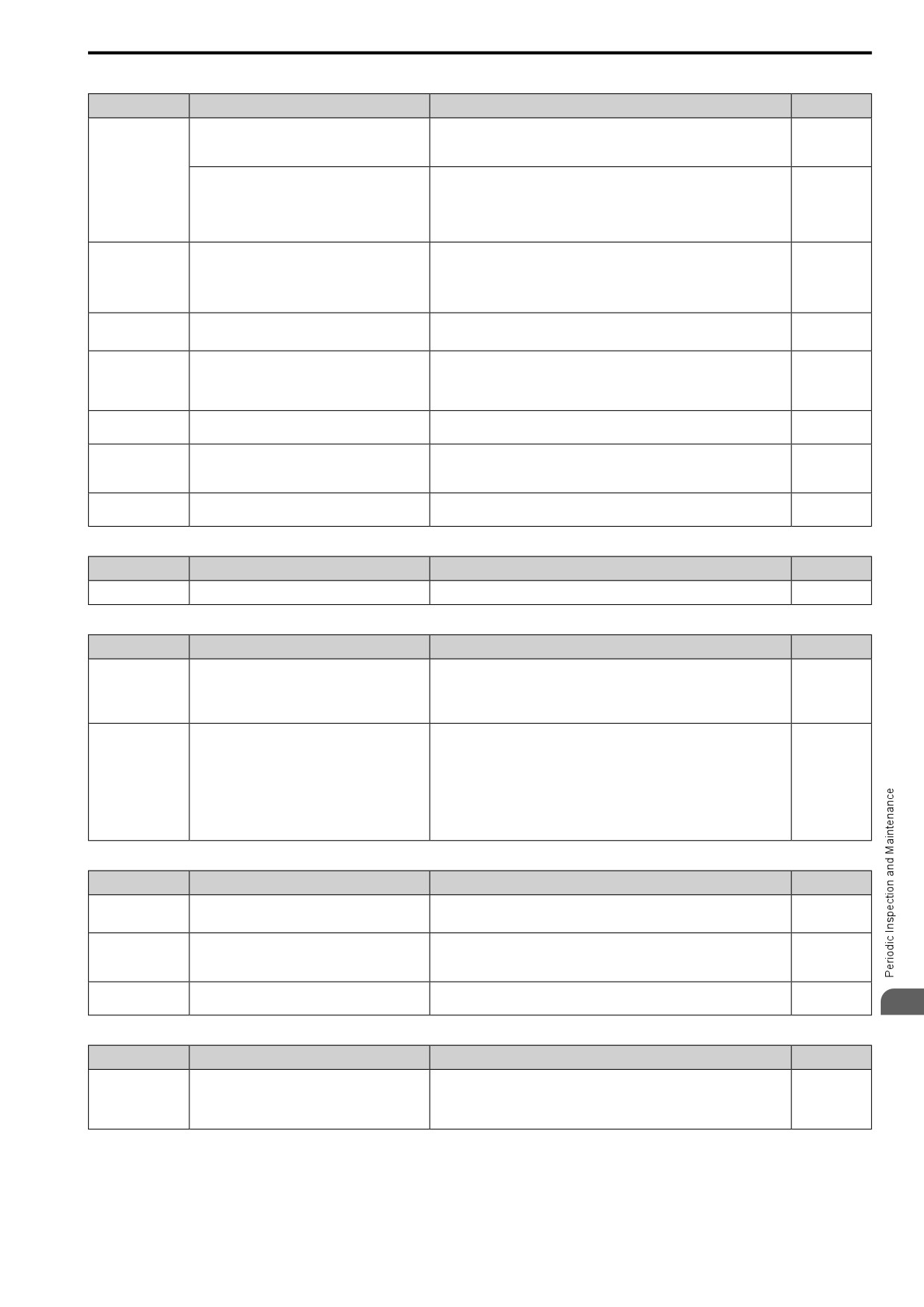
8.2
Inspection
Table 8.2 Main Circuit Periodic Inspection Checklist
Inspection Area
Inspection Points
Corrective Action
Checked
• Examine equipment for discoloration from too
• Replace damaged components as necessary.
much heat or deterioration.
• The drive does not have many serviceable parts and it could be necessary to
• Examine for damaged parts.
replace the drive.
General
• Examine enclosure door seal.
• Use a vacuum cleaner to remove unwanted particles and dust without
Examine for dirt, unwanted particles, or dust on
touching the components.
components.
• If you cannot remove unwanted particles and dust with a vacuum cleaner,
replace the components.
• Examine wiring and connections for discoloration
or damage. Examine wiring and connections for
Conductors and
discoloration from too much heat.
Repair or replace damaged wiring.
Wiring
• Examine wire insulation and shielding for
discoloration and wear.
Examine terminals for stripped, damaged, or loose
• Tighten loose screws.
Terminal Block
connections.
• Replace damaged screws.
• Examine contactors and relays for too much noise
Electromagnetic
during operation.
• Check coil voltage for overvoltage or undervoltage conditions.
Contactors and
Relays
• Examine coils for signs of too much heat, such as
• Replace broken relays, contactors, or circuit boards that you can remove.
melted or broken insulation.
Dynamic Braking
Examine the insulation for discoloration from too
If there is discoloration in the option, check to make sure that there is not damage
Option
much heat.
to the wiring. A small quantity of discoloration is not a problem.
• Examine for leaks, discoloration, or cracks.
Electrolytic
The drive does not have many serviceable parts and it could be necessary to
Capacitor
• Examine if the cap has come off, if there is
replace the drive.
swelling, or if there are leaks from broken sides.
Diodes, IGBT
Examine for dust or other unwanted material
Use a vacuum cleaner to remove unwanted particles and dust without touching
(Power Transistor)
collected on the surface.
the components.
Table 8.3 Motor Periodic Inspection Checklist
Inspection Area
Inspection Points
Corrective Action
Checked
Operation Check
Check for increased vibration or unusual noise.
Stop the motor and contact approved maintenance personnel as necessary.
Table 8.4 Control Circuit Periodic Inspection Checklist
Inspection Area
Inspection Points
Corrective Action
Checked
• Examine terminals for stripped, damaged, or
• Tighten loose screws.
loose connections.
• Replace damaged screws or terminals.
General
• Make sure that all terminals have been correctly
• If terminals are integral to a circuit board, it could be necessary to replace the
tightened.
control board or the drive.
• Tighten loose connections.
• Use a vacuum cleaner to remove unwanted particles and dust without
• Check for odor, discoloration, or rust.
touching the components.
• Make sure that all connections are correctly
• If you cannot remove unwanted particles and dust with a vacuum cleaner,
Circuit Boards
fastened.
replace the components.
• Make sure that the surface of the circuit board
• Do not use solvents to clean the board.
does not have dust or oil mist.
• The drive does not have many serviceable parts and it could be necessary to
replace the drive.
Table 8.5 Cooling System Periodic Inspection Checklist
Inspection Area
Inspection Points
Corrective Action
Checked
• Check for unusual oscillation or unusual noise.
Cooling fan
Clean or replace the fans as necessary.
• Check for damaged or missing fan blades.
• Examine for dust or other unwanted material
Heatsink
collected on the surface.
Use a vacuum cleaner to remove unwanted particles and dust without touching
the components.
• Examine for dirt.
Examine air intake, exhaust openings and make sure
Air Duct
Clear blockages and clean air duct as necessary.
that there are no unwanted materials on the surface.
8
Table 8.6 Keypad Periodic Inspection Checklist
Inspection Area
Inspection Points
Corrective Action
Checked
• Make sure that the keypad shows the data
• Clean the keypad.
correctly.
General
• If you have problems with the display or the keys, contact the manufacturer or
• Examine for dust or other unwanted material that
your nearest sales representative.
collected on components in the area.
271
8.3 Maintenance
8.3
Maintenance
The drive Maintenance Monitors keep track of component wear and tell the user when the end of the estimated
performance life is approaching. The Maintenance Monitors prevent the need to shut down the full system for
unexpected problems. Users can set alarm notifications for the maintenance periods for these drive components:
• Cooling fan
• Electrolytic capacitor
• Soft charge bypass relay
• IGBT
Contact the manufacturer or your nearest sales representative for more information about part replacement.
◆ Replaceable Parts
You can replace these parts of the drive:
• Cooling fan
If there is a failure in the main circuit, replace the drive.
If the drive is in the warranty period, contact the manufacturer or your nearest sales representative before you
replace parts. The manufacturer reserves the right to replace or repair the drive as specified by the applicable
warranty policy.
DANGER! Electrical Shock Hazard. Do not examine, connect, or disconnect wiring on an energized drive. Before servicing,
disconnect all power to the equipment and wait for the time specified on the warning label at a minimum. The internal capacitor
stays charged after the drive is de-energized. The charge indicator LED extinguishes when the DC bus voltage decreases
below 50 Vdc. When all indicators are OFF, measure for dangerous voltages to make sure that the drive is safe. If you do work
on the drive when it is energized, it will cause serious injury or death from electrical shock. The drive has internal capacitors that
stay charged after you de-energize the drive.
◆ Part Replacement Guidelines
When you replace these parts, make sure that you use original replacement parts for the applicable model and
design revision number of your drive.
Table 8.7 Standard Replacement Period
Parts
Standard Replacement Period
Cooling fan
10 years
Electrolytic capacitor *1
10 years
*1
If there is damage to parts that you cannot repair or replace, replace the drive.
Note:
Performance life estimate is based on these use conditions. These conditions are provided for the purpose of replacing parts to maintain
performance. Some parts may require more frequent replacement due to poor environments or rigorous use. Operating conditions for
performance life estimate: Ambient temperature: Yearly average of 40 °C (IP20/UL Open Type), Load factor: 80%, Operating rate: 24
hours a day
◆ Monitors that Display the Lifespan of Drive Components
The drive keypad shows percentage values for the replacement parts to help you know when you must replace
those components. Use the monitors in Table 8.8 to check replacement periods. When the monitor value is 100%,
the component is at the end of its useful life and there is an increased risk of drive malfunction. The manufacturer
recommends that you check the maintenance period regularly to make sure that you get the maximum
performance life.
Table 8.8 Performance Life Monitors
Monitor No.
Parts
Description
Shows the total operation time of fans as 0 to 99999 hours. After this value is 99999, the drive automatically
U4-03
resets it to 0.
Cooling fan
U4-04
Shows the total fan operation time as a percentage of the specified maintenance period.
U4-05
Electrolytic Capacitor
Shows the total capacitor usage time as a percentage of the specified maintenance period.
U4-06
Soft charge bypass relay
Shows the number of times the drive is energized as a percentage of the performance life of the inrush circuit.
U4-07
IGBT
Shows the percentage of the maintenance period for the IGBTs.
272
8.3 Maintenance
◆ Alarm Outputs for Maintenance Monitors
You can use H2-xx [MFDO Function Select] to send a message that tells you when a specified component is near
the end of its performance life estimate. Set the applicable value to H2-xx as shown in Table 8.9 for your
component.
When the specified component is near the end of its performance life estimate, the MFDO terminals set for H2-xx
= 63 [Maintenance] will activate, and the keypad will show an alarm that identifies the component to replace.
Table 8.9 Maintenance Period Alarms
Digital Outputs
Display
Alarm Name
Cause
Possible Solutions
(Setting Value in
H2-xx)
Cooling Fan
The cooling fan is at 90% of its expected
Replace the cooling fan, then set o4-03 = 0 [Fan.Oper
LT-1
Maintenance Time
performance life.
Setting = 0 h] to reset the cooling fan operation time.
The capacitors for the main circuit and
Replace the board or the drive.
Capacitor
LT-2
control circuit are at 90% of expected
Contact the manufacturer or your nearest sales
Maintenance Time
performance life.
representative to replace the board.
63
Replace the board or the drive.
SoftChargeBypassRe
The soft charge bypass relay is at 90% of its
LT-3
Contact the manufacturer or your nearest sales
lay MainteTime
performance life estimate.
representative to replace the board.
IGBT Maintenance
The IGBT is at 50% of its expected
Check the load, carrier frequency, and output frequency.
LT-4
Time (50%)
performance life.
IGBT Maintenance
The IGBT is at 90% of its expected
Replace the IGBT or the drive.
TrPC
4
Time (90%)
performance life.
◆ Related Parameters
Replace the component, then set Maintenance Setting o4-03, o4-05, o4-07, and o4-09 = 0 to reset the
Maintenance Monitor. If these parameters are not reset after the corresponding parts have been replaced, the
Maintenance Monitor function will continue to count down the performance life from the value that was reached
with the old part. If the Maintenance Monitor is not reset, the drive will not have the correct value of the
performance life for the new component.
Note:
The maintenance period changes for different operating environments.
Table 8.10 Maintenance Setting Parameters
No.
Name
Function
o4-03
Fan.Oper Setting
Sets the value from which to start the cumulative drive cooling fan operation time in 10-hour units.
Note:
When o4-03 = 30 has been set, the drive will count the operation time for the cooling fan from 300 hours
and U4-03 [Fan Oper.Time] will show 300 h.
o4-05
Cap.Maint.Setting
Sets the value from which to start the count for the main circuit capacitor maintenance period as a percentage.
o4-07
PreChgRly Preset Maintenance Cnt
Sets as a percentage the value from which to start the count for the soft charge bypass relay maintenance
time.
o4-09
IGBT Preset Maintenance Cnt
Sets the value from which to start the count for the IGBT maintenance period as a percentage.
8
273
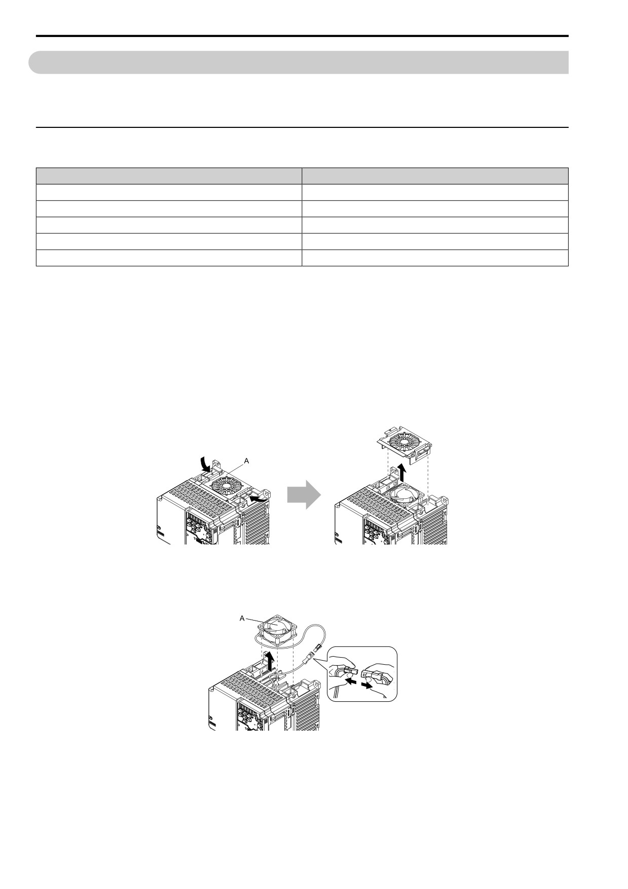
8.4 Replace Cooling Fans
8.4
Replace Cooling Fans
NOTICE: Use the instructions in this manual to replace the cooling fans. When you do maintenance on the fans, replace all the
fans to increase product life. If you install the fans incorrectly, it can cause damage to the drive.
To replace a cooling fan, contact the manufacturer or your nearest sales representative.
◆ Replace the Cooling Fan
Table 8.11 Applicable Models
Model
Cooling Fans
2006 - 2021
1
2042 - 2082
2
B010, B012
1
4005 - 4012
1
4031 - 4060
2
DANGER! Electrical Shock Hazard. Do not examine, connect, or disconnect wiring on an energized drive. Before servicing,
disconnect all power to the equipment and wait for the time specified on the warning label at a minimum. The internal capacitor
stays charged after the drive is de-energized. The charge indicator LED extinguishes when the DC bus voltage decreases
below 50 Vdc. When all indicators are OFF, measure for dangerous voltages to make sure that the drive is safe. If you do work
on the drive when it is energized, it will cause serious injury or death from electrical shock. The drive has internal capacitors that
stay charged after you de-energize the drive.
CAUTION! Burn Hazard. Do not touch a hot drive heatsink. De-energize the drive, wait for a minimum of 15 minutes, then make
sure that the heatsink is cool before you replace the cooling fans. If you touch a hot drive heatsink, it can burn you.
NOTICE: Use the instructions in this manual to replace the cooling fans. When you do maintenance on the fans, replace all the
fans to increase product life. If you install the fans incorrectly, it can cause damage to the drive.
■ Remove a Fan
1. To remove the fan finger guard from the drive, push the hooks on the left and right sides of it and pull up.
A - Fan finger guard
Figure 8.1 Remove the Fan Finger Guard
2. Pull the cooling fan straight up from the drive. Disconnect the power supply connector and remove the fan
from the drive.
A - Cooling fan
Figure 8.2 Remove the Cooling Fan
■ Install a Fan
Reverse the removal procedure to install a cooling fan.
274
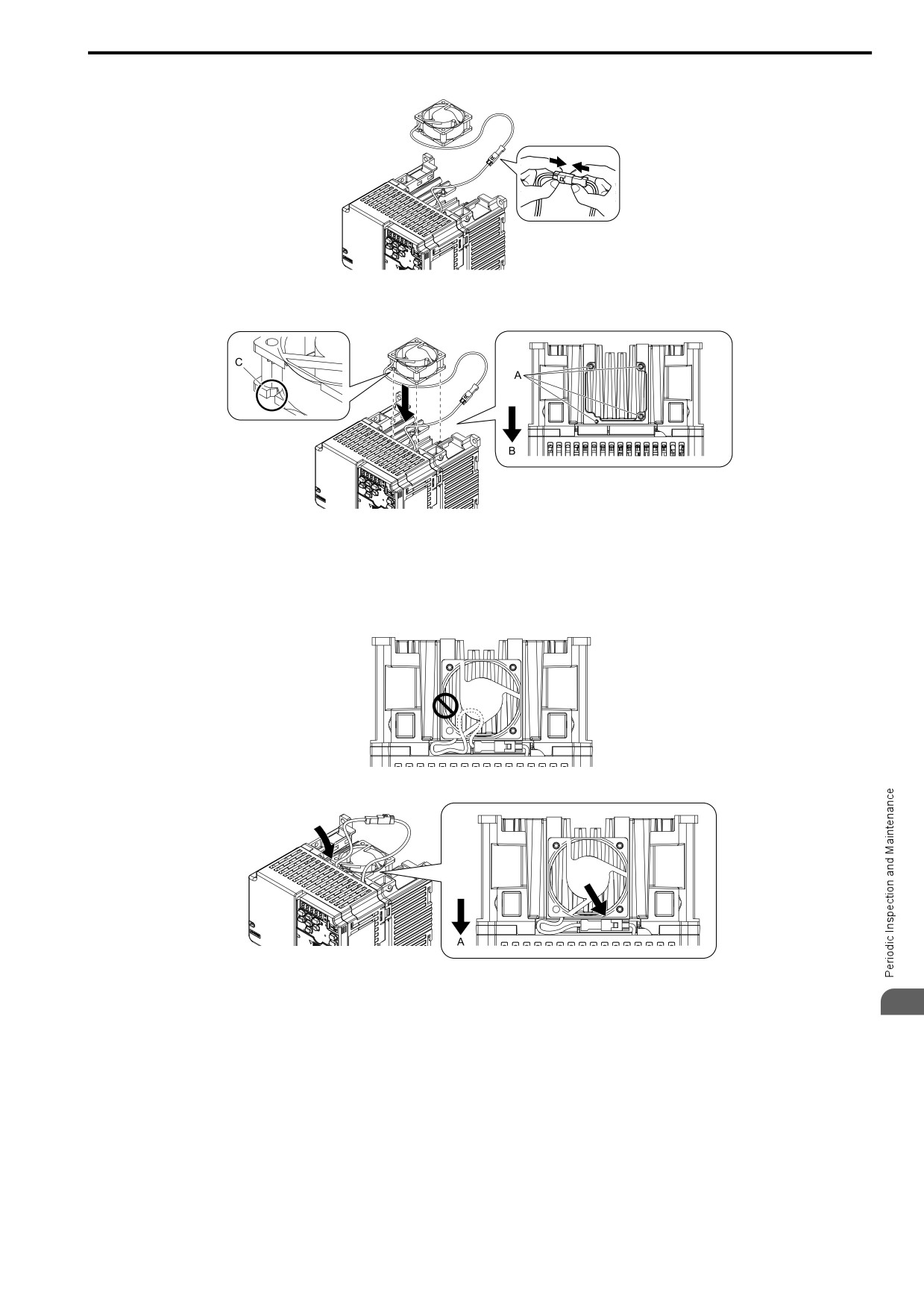
8.4 Replace Cooling Fans
1. Connect the power supply connector between the drive and cooling fan.
Figure 8.3 Connect the Power Supply Connector
2. Align the notches on the fan with the pins on the drive and install the cooling fans in the drive.
A - Alignment pins on drive
C - Notch on fan
B - Front of drive
Figure 8.4 Install the Cooling Fan
Note:
When you install the cooling fan, make sure that you do not pinch cables between the cooling fan and the drive.
3. Put the cable and connector in the
recess
of
the drive.
A - Front of drive
8
Figure 8.5 Put the Cable and Connector in
the Drive Recess
275
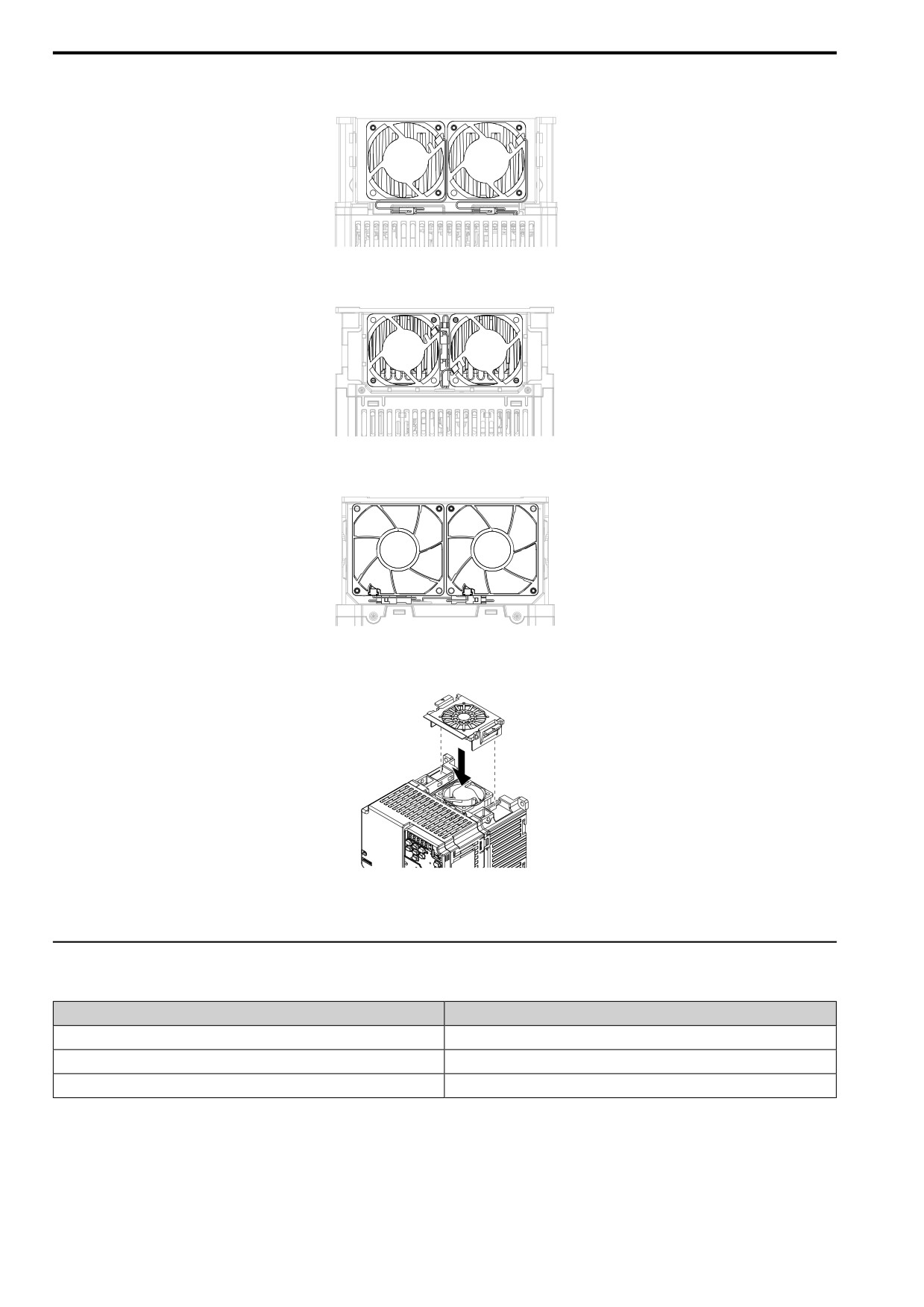
8.4 Replace Cooling Fans
Note:
The connector installation position is different for different models.
Figure
8.6
Put
the
Connector
in the Recess
Figure 8.7
Put
the
Connector in Between the Fans
Figure 8.8 Put the Connector
in
Between the
Drive and Fan
4. Insert the fan cover straight until the
hook
clicks into
place.
Figure 8.9 Reattach the Fan Finger Guard
5. Energize the drive and set o4-03 = 0 [Fan.Oper Setting = 0 h] to reset the cooling fan operation time.
◆ Replace the Cooling Fan
Table 8.12 Applicabel Models
Model
Cooling Fans
2030
1
B018
2
4018, 4023
1
DANGER! Electrical Shock Hazard. Do not examine, connect, or disconnect wiring on an energized drive. Before servicing,
disconnect all power to the equipment and wait for the time specified on the warning label at a minimum. The internal capacitor
stays charged after the drive is de-energized. The charge indicator LED extinguishes when the DC bus voltage decreases
below 50 Vdc. When all indicators are OFF, measure for dangerous voltages to make sure that the drive is safe. If you do work
on the drive when it is energized, it will cause serious injury or death from electrical shock. The drive has internal capacitors that
stay charged after you de-energize the drive.
276