Q2V Driving Quality. Technical Manual (Item code: Q2V-Axxxx-xxx, 2020) - page 5
5.2 European Standards
5. Connect an AC reactor or DC reactor to decrease harmonic distortion. Refer to DC Reactor Selection on
page 165 to select a DC reactor.
Note:
• To maintain compliance with EN 61000-3-2 on drive models 2001 to 2006, 4001 to 4004, install a DC reactor.
Ground Wiring
WARNING! Electrical Shock Hazard. Do not remove covers or touch circuit boards while the drive is energized. If you touch the
internal components of an energized drive, it can cause serious injury or death.
WARNING! Electrical Shock Hazard. Ground the neutral point on the power supply of drive models 2xxxE, BxxxE, and 4xxxE to
comply with the EMC Directive before you turn on the EMC filter or if there is high resistance grounding. If the EMC filter is
switched ON without the neutral point being grounded or if there is high resistance grounding, it can cause death or serious
injury.
Enable the Internal EMC Filter
On drive models 2xxxE, BxxxE, and 4xxxE, move the screw or screws to turn ON and OFF (enable and disable)
the EMC filter.
Make sure that the symmetric grounding network is applied, and install the screw or screws in the ON position to
enable the built-in EMC filter in compliance with the EMC Directive. The EMC filter switch screw or screws are
installed in the OFF position by default.
WARNING! Electrical Shock Hazard. Disconnect all power to the drive, wait for the time specified on the warning label, and
check the drive for dangerous voltages before you remove covers or touch EMC filter screws. If you touch the screws when
there are dangerous voltages, it will cause serious injury or death.
WARNING! Electrical Shock Hazard. Do not remove covers or touch circuit boards while the drive is energized. If you touch the
internal components of an energized drive, it can cause serious injury or death.
WARNING! Electrical Shock Hazard. Ground the neutral point on the power supply of drive models 2xxxE, BxxxE, and 4xxxE to
comply with the EMC Directive before you turn on the EMC filter or if there is high resistance grounding. If the EMC filter is
switched ON without the neutral point being grounded or if there is high resistance grounding, it can cause death or serious
injury.
WARNING! Electrical Shock Hazard. Connect the ground cable correctly. If you touch electrical equipment that is not grounded,
it can cause serious injury or death.
NOTICE: To disable the internal EMC filter, move the screws from ON to OFF and then tighten to the specified torque. If you
fully remove the screws or tighten the screws to an incorrect torque, it can cause drive failure.
NOTICE: Move the EMC switch screw or screws to the OFF position for networks that are not symmetrically grounded. If the
screws are not in the correct position, it can cause damage to the drive.
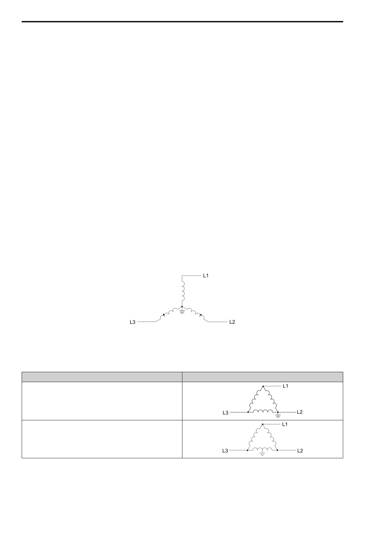
Figure 5.7 Symmetric Grounding
NOTICE: When you use the drive with a non-grounding, high-resistance grounding, or asymmetric-grounding network, put the
EMC Filter screw or screws in the OFF position to disable the built-in EMC filter. Failure to obey the instructions can damage the
drive.
Table 5.8 Asymmetric Grounding Networks
Type of Grounding
Diagram
Grounded at the corner of the delta connection
Grounded at the middle of the side
160
5.2 European Standards
Type of Grounding
Diagram
Single-phase,
grounded at the end
point
Three-phase variable transformer without solidly grounded neutral
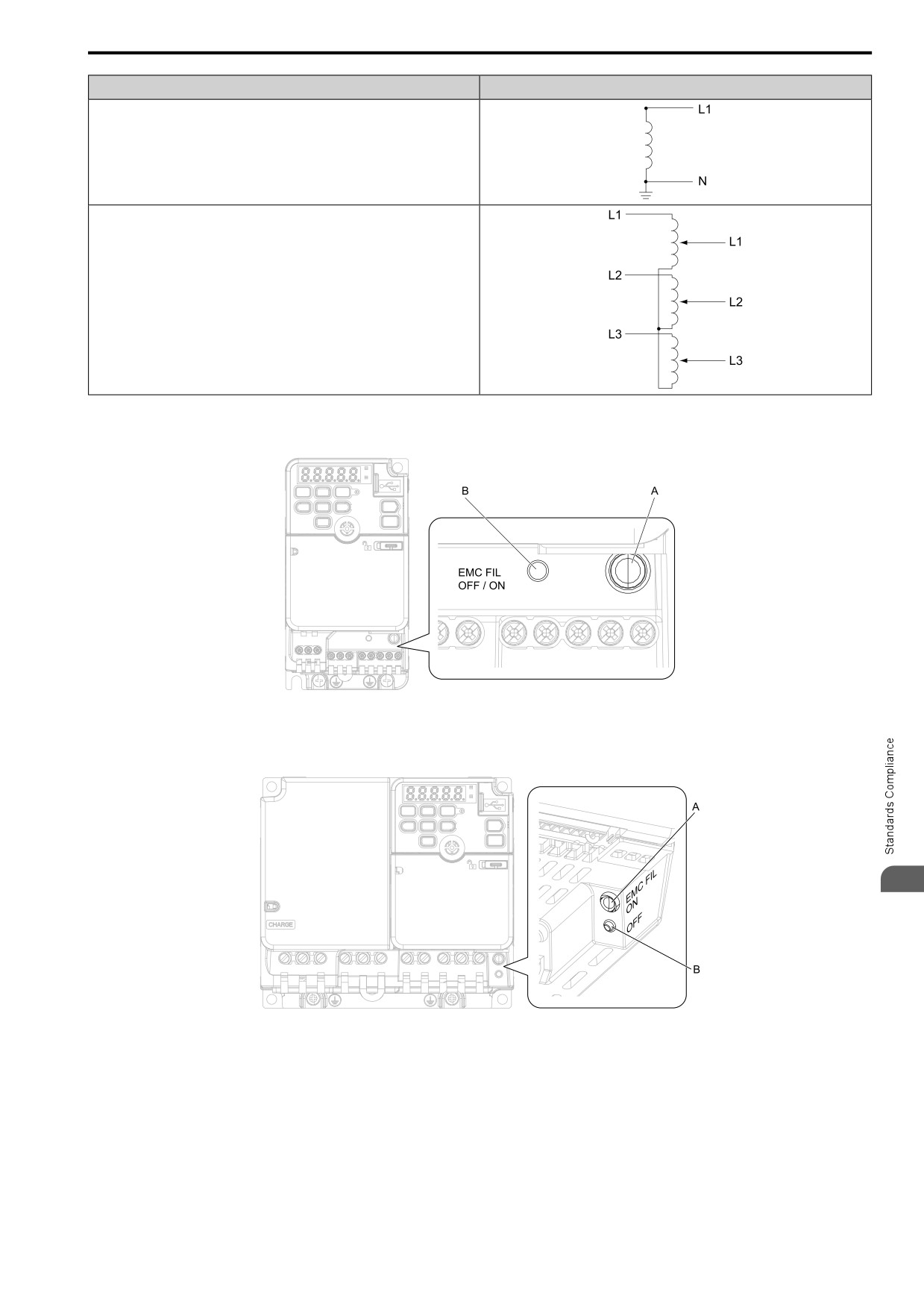
EMC Filter Switch Location
A
-
SW (ON)
B
-
SW (OFF)
Figure 5.8 EMC Filter Switch Location (Models 2001E - 2006E, B001E
-
B004E)
5
A - SW (ON)
B - SW (OFF)
Figure 5.9
EMC Filter Switch Location (Models 2010E - 2021E, B006E - B012E, 4001E - 4012E)
161
5.2 European Standards
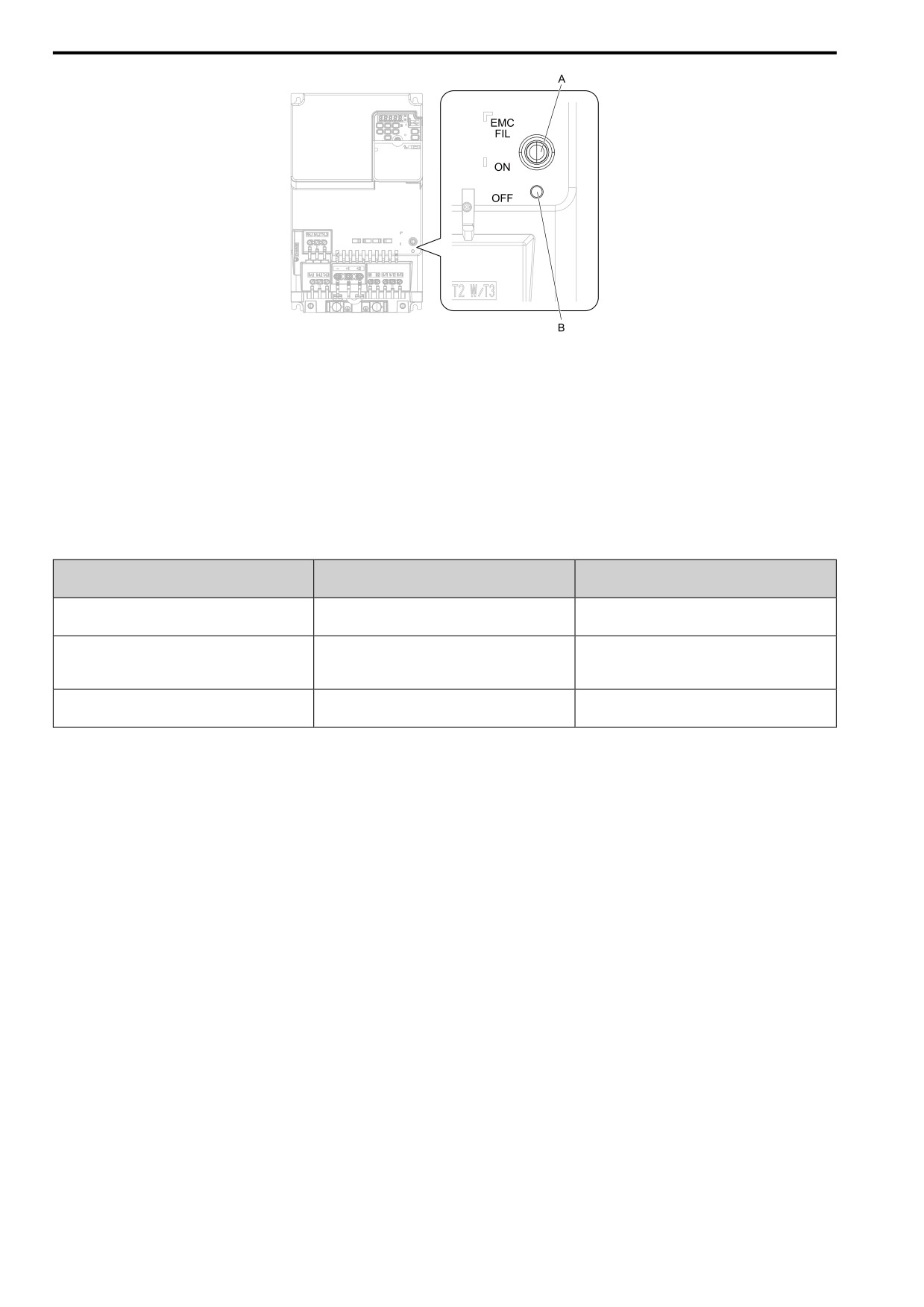
A - SW
(ON)
B - SW (OFF)
Figure 5.10
EMC Filter
Switch
Location
(Models
2030E - 2082E, 4018E - 4060E)
NOTICE: Only use the screws specified in this manual. If you
use screws that are not
approved, it can cause damage to the
drive.
EMC Filter Switch Screws
If you lose an EMC filter switch screw, use this information to find the correct replacement screw and install the
new screw with the correct tightening torque.
Table 5.9 Screw Sizes and Tightening Torques
Tightening Torque
Model
Screw Size
N∙m (in∙lb)
2001 - 2006
0.5
- 0.7
M3 × 16
B001 - B004
(4.4
- 6.2)
2010 - 2021
0.5
- 0.7
B006 - B012
M3 × 20
(4.4
- 6.2)
4001 - 4012
2030 - 2082
1.0
- 1.3
M4 × 20
4018 - 4060
(8.9
- 11.5)
■ Installing the External EMC Noise Filter
Drive models 2xxxA, BxxxA, and 4xxxA must meet conditions in this section to comply with EN 61800-3.
Connect an EMC noise filter to the input side (primary side) that complies with European standards as specified
by Yaskawa. Refer to External EMC Noise Filter Selection on page 164 to select the correct EMC noise filter.
Use this procedure to install an EMC noise filter to make equipment and devices added to the drive comply with
the EMC Directive.
1. Install the drive and EMC noise filter on the same grounded metal plate.
2. Wire the drive and motor.
162
5.2 European Standards
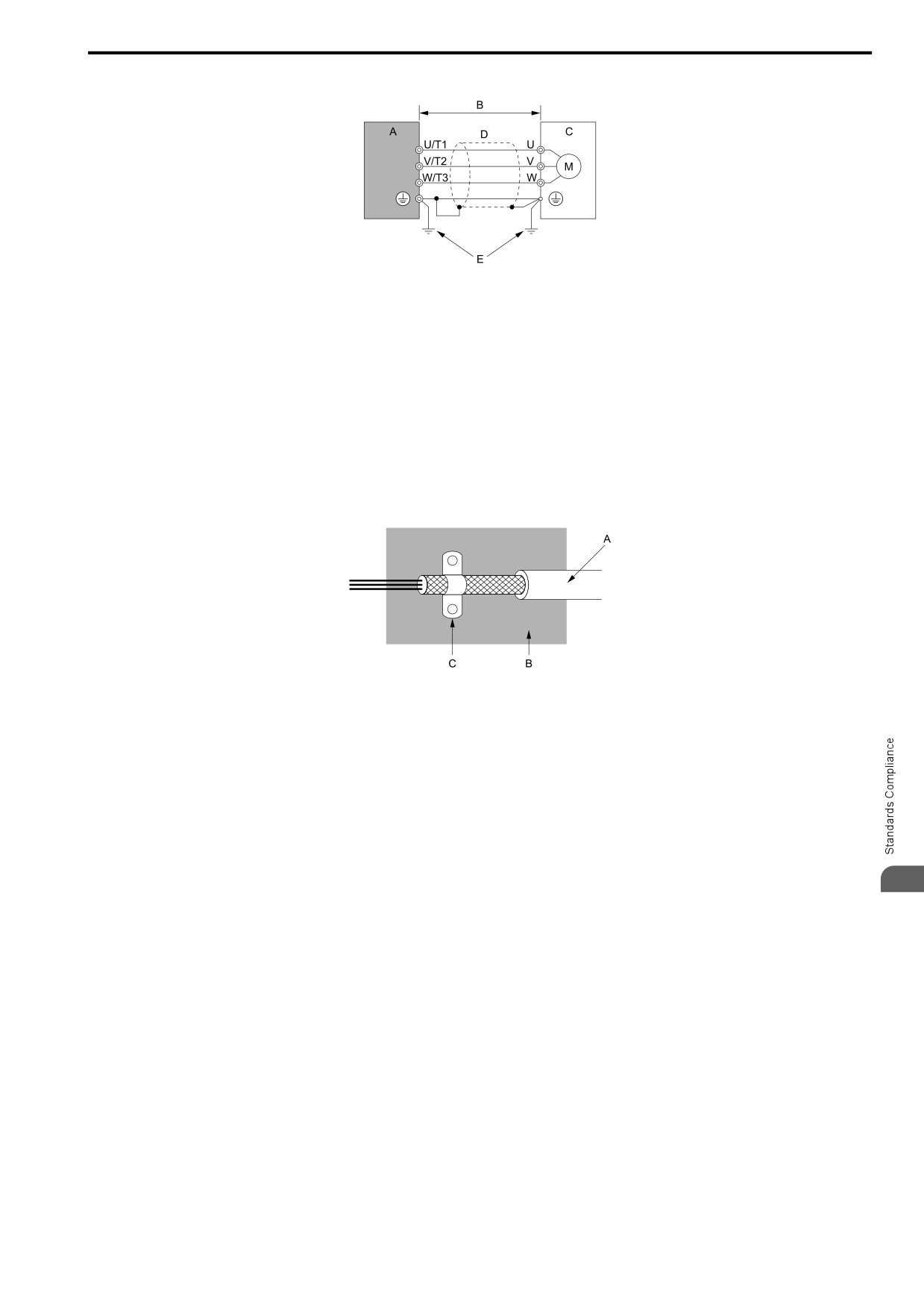
3. Ground the wire shielding on the drive side and motor side.
A - Drive
D - Metal conduit
B - 10 m (32.8 ft) maximum
E - Grounding wire
C - Motor
Figure 5.11 Wiring the Drive and Motor
Note:
• Use a braided shield cable for the drive and motor wiring or put the wires through a metal conduit.
• Keep the wire as short as possible. The maximum wiring length between the drive and motor is:
-2xxxA, BxxxA, 4xxxA: 10 m (32.8 ft)
• Keep the grounding wire as short as possible.
4. Use a cable clamp to ground the motor cable to the metal plate.
Note:
Make sure that the protective ground wire complies with technical specifications or local safety standards.
A - Braided shield cable
C - Cable clamp (conductive)
B - Metal plate
Figure 5.12 Ground the shield
5
163
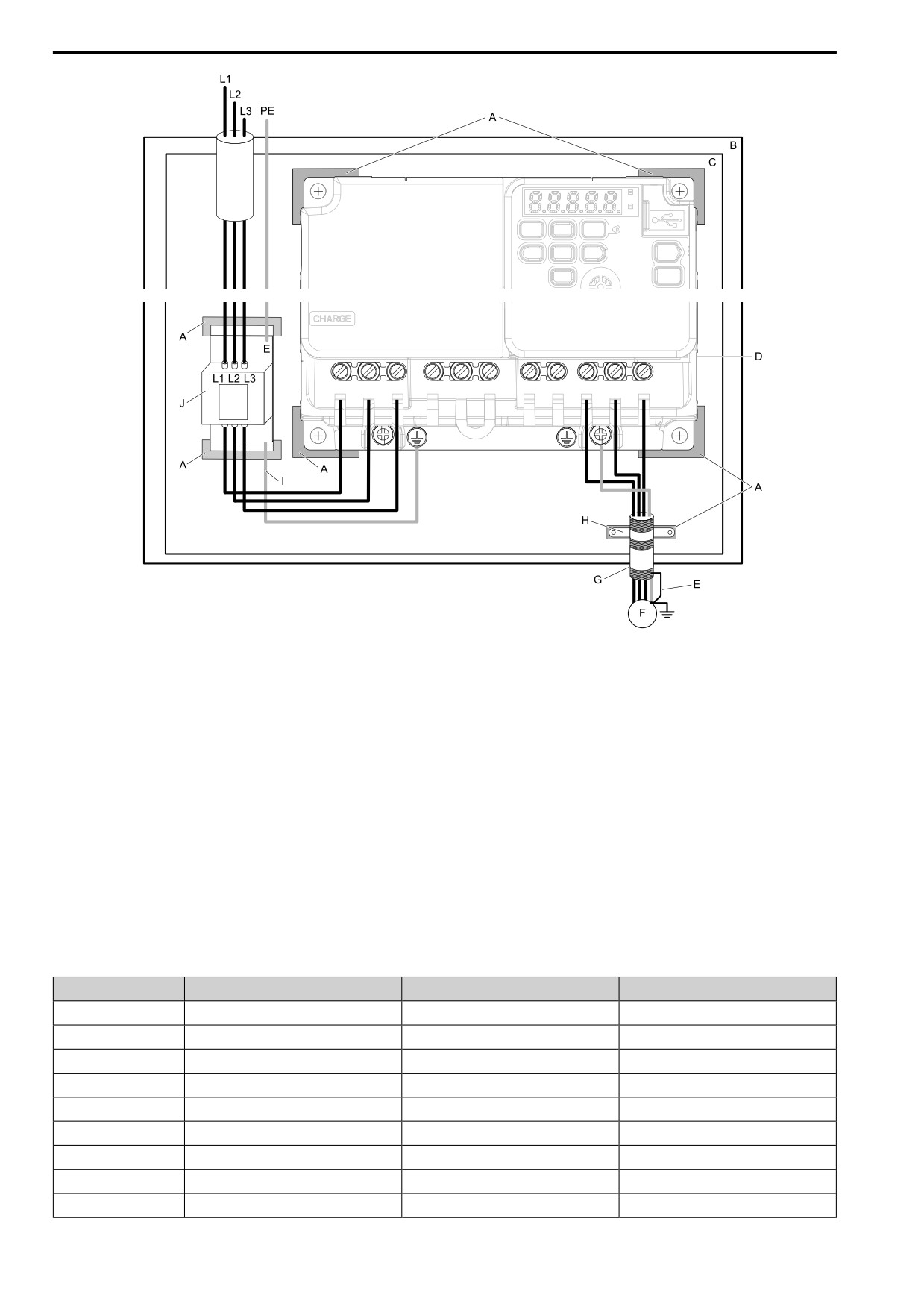
5.2 European Standards
A - Grounding surface (Remove any paint or
F - Motor
sealant.)
G - Motor cable (Braided shield cable: 10 m (32.8 ft)
B - Enclosure panel
maximum)
C - Metal plate
H - Cable clamp
D - Drive
I - Grounding wire
E - Ground the shield.
J - EMC noise filter
Figure 5.13 EMC Noise Filter and Drive Installation Procedure
5. Connect the DC reactor to decrease harmonic distortion.
Refer to DC Reactor Selection on page 165 to select a DC reactor.
Note:
• To maintain compliance with EN 61000-3-2 on drive models 2001 to 2006, 4001 to 4004, install a DC reactor.
Ground Wiring
WARNING! Electrical Shock Hazard. Do not remove covers or touch circuit boards while the drive is energized. If you touch the
internal components of an energized drive, it can cause serious injury or death.
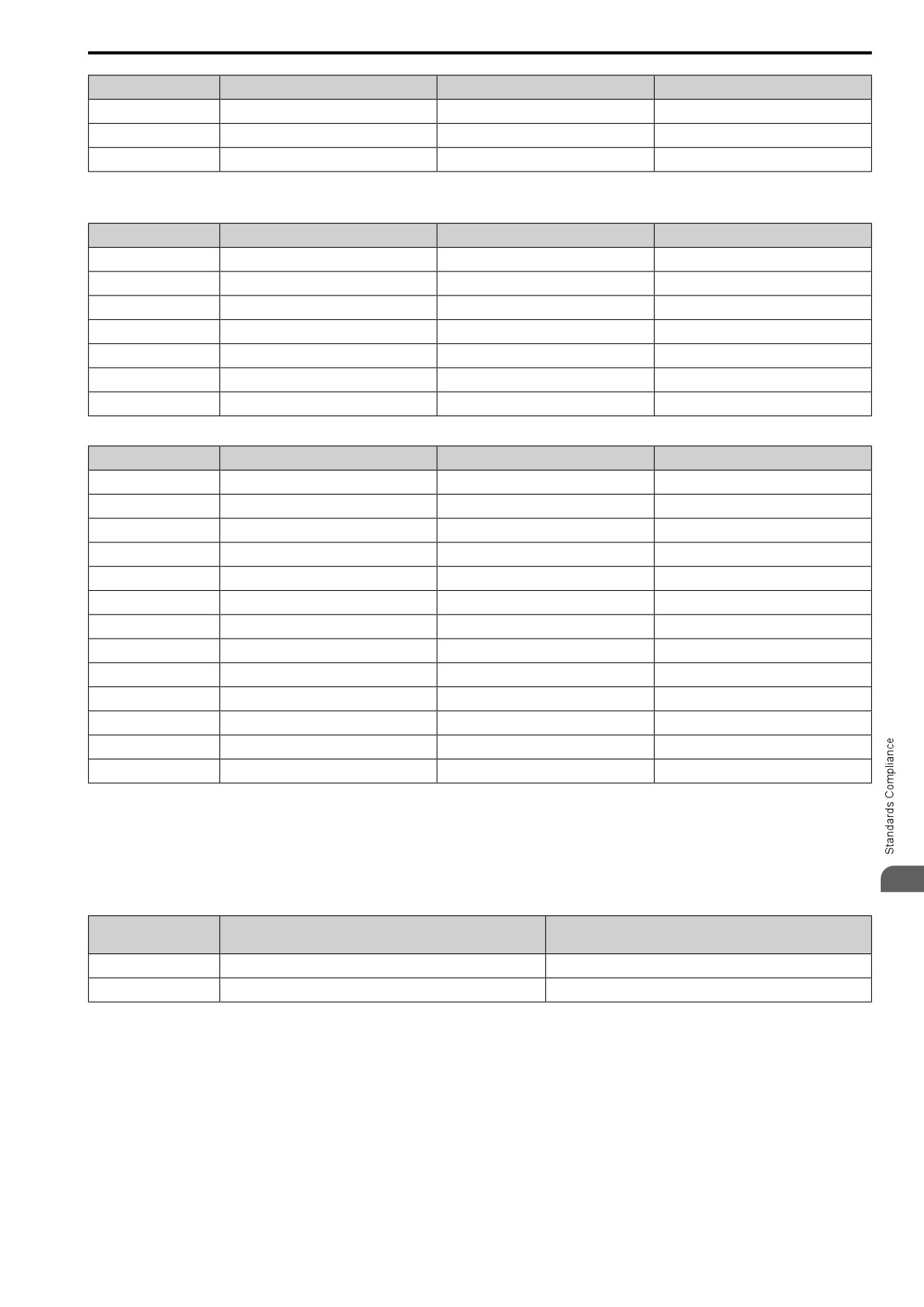
External EMC Noise Filter Selection
Table 5.10 External EMC Noise Filter (2xxxA)
Drive model
EMC Noise Filter Model
Quantity
Manufacturer
2001
FS23637-8-07
1
Schaffner
2002
FS23637-8-07
1
Schaffner
2004
FS23637-8-07
1
Schaffner
2006
FS23637-8-07
1
Schaffner
2010
FS23637-14-07
1
Schaffner
2012
FS23637-14-07
1
Schaffner
2021
FS23637-24-07
1
Schaffner
2030
FS5973-35-07 *1
1
Schaffner
2042
FS5973-60-07 *1
1
Schaffner
164
5.2
European Standards
Drive model
EMC Noise Filter Model
Quantity
Manufacturer
2056
FS5973-100-07 *1
1
Schaffner
2070
FS5973-100-07 *1
1
Schaffner
2082
RTEN-5200
1
TDK
*1
When you install an external EMC noise filter, change the terminals or use the junction terminal.
Table 5.11
External EMC Noise Filter (BxxxA)
Drive model
EMC Noise Filter Model
Quantity
Manufacturer
B001
FS23638-10-07
1
Schaffner
B002
FS23638-10-07
1
Schaffner
B004
FS23638-10-07
1
Schaffner
B006
FS23638-20-07
1
Schaffner
B010
FS23638-20-07
1
Schaffner
B012
FS23638-30-07
1
Schaffner
B018
FS23638-40-07
1
Schaffner
Table 5.12
External EMC Noise Filter (4xxxA)
Drive model
EMC Noise Filter Model
Quantity
Manufacturer
4001
FS23639-5-07
1
Schaffner
4002
FS23639-5-07
1
Schaffner
4004
FS23639-5-07
1
Schaffner
4005
FS23639-10-07
1
Schaffner
4007
FS23639-10-07
1
Schaffner
4009
FS23639-10-07
1
Schaffner
4012
FS23639-15-07
1
Schaffner
4018
FS5972-35-07 *1
1
Schaffner
4023
FS5972-35-07 *1
1
Schaffner
4031
FS5972-60-07 *1
1
Schaffner
4038
FS5972-60-07 *1
1
Schaffner
4044
RTEN-5100
1
TDK
4060
RTEN-5100
1
TDK
*1
When you install an external EMC noise filter, change the terminals or use the junction terminal.
■ DC Reactor Selection
To comply with EN 61000-3-2, install a DC reactor to drive models 2001 to 2006, and 4001 to 4004 when you use
an internal or external EMC filter.
5
Table 5.13 DC Reactors for Harmonic Suppression
DC Reactor Model
Drive Model
Rating
Manufacturer: Yaskawa
2001 - 2006
UZDA-B
5.4A, 8mA
4001 - 4004
UZDA-B
3.2A, 28mA
165
5.3 UL Standards
5.3
UL Standards
Figure 5.14 UL/cUL Mark
The UL/cUL Mark indicates that this product satisfies stringent safety standards. This mark appears on products
in the United States and Canada. It shows UL approval, indicating that it has been determined that the product
complies with safety standards after undergoing strict inspection and assessment. You must use UL Listed or UL
Recognized parts for all primary components that are built into electrical equipment that has UL approval.
This product has been tested in accordance with UL standard UL61800-5-1, and has been verified to be in
compliance with UL standards.
Machines and devices integrated with this product must satisfy the following conditions for compliance with UL
standards.
◆ Area of Use
Install this product in a location with Overvoltage Category III and pollution degree 2 or less as specified in
UL61800-5-1.
■ Ambient Temperature Setting
Maintain the ambient temperature within the following ranges according to the enclosure type.
• IP20/UL Type 1: -10 °C to +40 °C (14 °F to 104 °F)
• IP20/UL Open Type: -10 °C to +50 °C (14 °F to 122 °F)
◆ Wire the Main Circuit Terminal Block
Wire the main circuit terminal block correctly as specified by the instructions in the manual.
To select the correct wire gauge, refer to Main Circuit Wire Gauges and Tightening Torques (UL Compliance) on
page 167.
■ Notes on Wiring the Main Circuit Terminal Block
Read these notes before you wire the main circuit terminal block.
• Use UL-Listed, vinyl-coated insulated copper wires for operation with a continuous maximum permitted
temperature of 75 °C at 600 V.
• Remove all unwanted objects that are near the terminal block connections.
• Remove the insulation from the connection wires to the wire stripping lengths shown in the manual.
• Do not use bent or crushed wires. Remove the damaged end of the wire before you use it. Incorrect connections
can cause death or serious injury from fire.
• Do not solder stranded wire. Soldered wire connections can become loose over time and cause unsatisfactory
drive performance.
• If you use stranded wire, make sure that all of the wire strands are in the connection. Also, do not twist the
stranded wire too much. Incorrect connections can cause death or serious injury from fire.
• Put the wire all the way into the terminal block. Remove the insulation from the wire to the recommended wire
stripping length to fit the wire with insulation in the plastic housing.
• Use a torque driver, torque ratchet, or torque wrench for the screws. A slotted driver or a hex tool will be
necessary to wire the screw clamp terminal. Use applicable tools as specified by the recommended conditions in
the product manual.
• If you use power tools to tighten the terminal screws, use a low speed setting (300 to 400 r/min). Failure to obey
can cause damage to the terminal screws.
• Wire gauges on existing drive models to be replaced may not match wire gauge ranges on new drives. Refer to
the drive manuals for correct wire sizes.
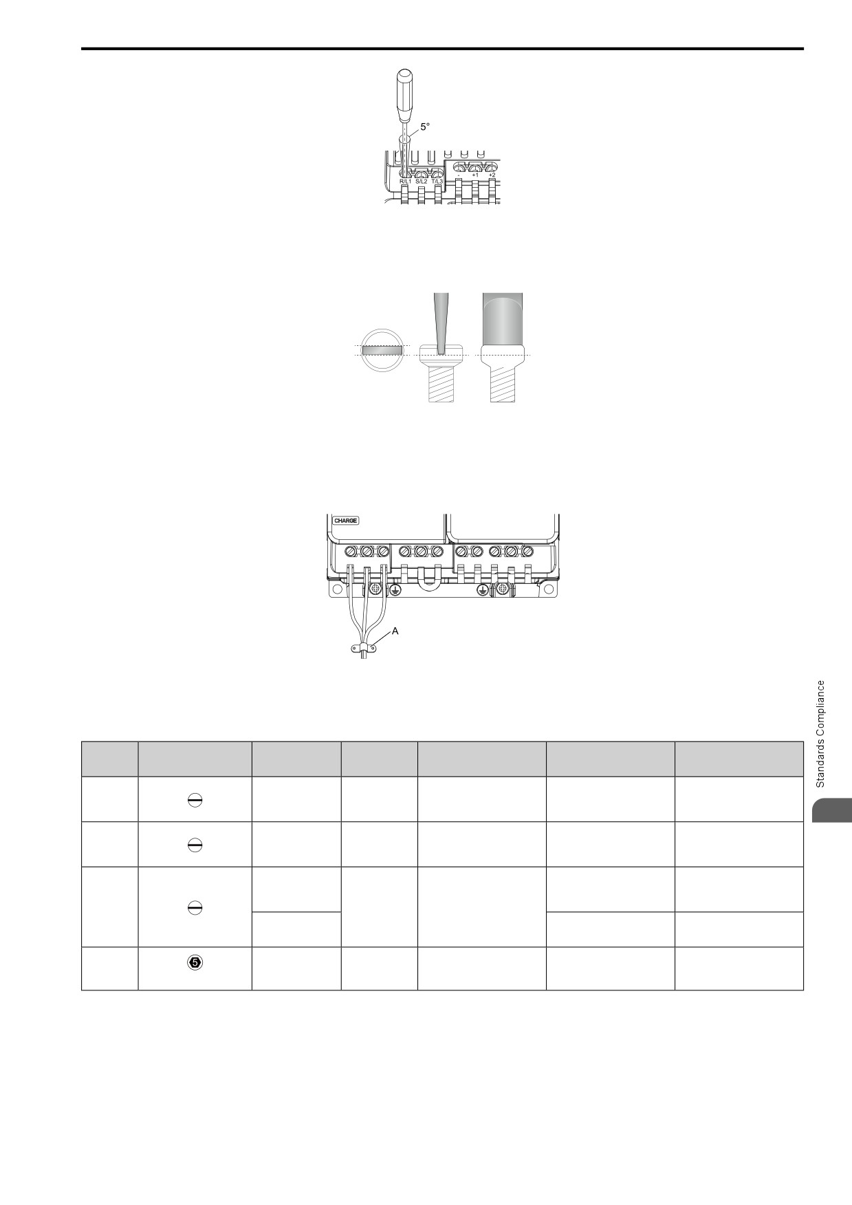
• Do not tighten the terminal screws at an angle of 5 degrees or more. Failure to obey can cause damage to the
terminal screws.
166
5.3 UL Standards
Figure 5.15 Permitted Angle
• Put the bit all the way into the hex socket to tighten
the hex socket cap screw.
• When you tighten slotted screws, hold the straight-edge
screwdriver
perpendicularly to the screw. Make sure
that you align the end of the straight-edge screwdriver with the
screw groove.
Figure 5.16 Tightening Slotted Screws
• After connecting the wires to the terminal block, lightly
pull on the wires to make sure that they do not come out
of the terminals.
• Do not let strain on the wiring cause damage. Use a strain relief near the wiring to release the tension. Refer to
Figure 5.17 for an example.
A - Cable clamp
Figure 5.17 Strain Relief Example
Table 5.14 Recommended Wiring Tools
Screw
Bit Model
Torque Driver Model
Torque Wrench
Screw Shape
Wire Gauge
Adapter
Size
(Manufacturer)
(Tightening Torque)
(Tightening Torque)
TSD-M 1,2NM
SF-BIT-SL 0,5X3,0-70
M3
-
Bit
(0.3 - 1.2 N∙m
-
(PHOENIX CONTACT)
(2.7 - 10.6 in∙lb))
5
TSD-M 3NM
SF-BIT-SL 1,0X4,0-70
M4
-
Bit
(1.2 - 3.0 N∙m
-
(PHOENIX CONTACT)
(10.6 - 26.6 in∙lb))
TSD-M 3NM
≤ 25 mm2
(1.2 - 3.0 N∙m
-
(AWG 10)
SF-BIT-SL 1,2X6,5-70
(10.6 - 26.6 in∙lb))
M5 *1
Bit
(PHOENIX CONTACT)
≥ 30 mm2
4.1 - 4.5 N∙m
-
(AWG 8)
(36.3 - 39.8 in∙lb) *2 *3
SF-BIT-HEX 5-50
5 - 9 N∙m
M6
-
Bit
-
(PHOENIX CONTACT)
(44.3 - 79.7 in∙lb) *2 *3
(WAF: 5 mm)
*1
When you wire drive models 2042, 2056, 4031, 4038, 4044, and 4060, select the correct tools for the wire gauge.
*2
Use 6.35 mm (0.25 in) bit socket holder.
*3
Use a torque wrench that can apply this torque measurement range.
■ Main Circuit Wire Gauges and Tightening Torques (UL Compliance)
Comply with local standards for correct wire gauges in the region where the drive is used.
167
5.3 UL Standards
WARNING! Electrical Shock Hazard. Make sure that the protective ground wire conforms to technical standards and local
safety regulations. The IEC/EN 61800-5-1:2007 standard specifies that you must wire the power supply to automatically de-
energize when the protective ground wire disconnects. If you turn on the internal EMC filter, the leakage current of the drive will
be more than 3.5 mA. You can also connect a protective ground wire that has a minimum cross-sectional area of 10 mm2
(copper wire). If you do not obey the standards and regulations, it can cause serious injury or death.
WARNING! Electrical Shock Hazard. Only connect peripheral options, for example a DC reactor or braking resistor, to terminals
+1, +2, -, B1, and B2. Failure to obey can cause serious injury or death.
Note:
• The recommended wire gauges are based on drive continuous current ratings with 75 °C (167 °F) 600 V class 2 heat-resistant indoor
PVC wire. Assume these conditions:
-Ambient temperature: 40 °C (104 °F) maximum
-Wiring distance: 100 m (3281 ft) maximum
-Normal Duty rated current value
• Refer to the instruction manual for each device for recommended wire gauges to connect peripheral devices or options to terminals +1,
+2, -, B1, and B2. Contact the manufacturer or your nearest sales representative if the recommended wire gauges for the peripheral
devices or options are out of the range of the applicable gauges for the drive.
Three-Phase 200 V Class (UL Compliance)
Wire
Terminal Screw
Recommended
Applicable Gauge
Stripping
Tightening Torque
Model
Terminal
Gauge
Length *1
AWG, kcmil
AWG, kcmil
Size
Shape
N∙m (in∙lb)
mm
0.5
- 0.6
R/L1, S/L2, T/L3
14
14
6.5
M3
(4.4
- 5.3)
0.5
- 0.6
U/T1, V/T2, W/T3
14
14
6.5
M3
(4.4
- 5.3)
0.5
- 0.6
2001
-, +1, +2
14
14
6.5
M3
(4.4
- 5.3)
0.5
- 0.6
B1, B2
14
14
6.5
M3
(4.4
- 5.3)
0.8
- 1.0
14 *2
14 *2
-
M3.5
(7.1
- 8.9)
0.5
- 0.6
R/L1, S/L2, T/L3
14
14
6.5
M3
(4.4
- 5.3)
0.5
- 0.6
U/T1, V/T2, W/T3
14
14
6.5
M3
(4.4
- 5.3)
0.5
- 0.6
2002
-, +1, +2
14
14
6.5
M3
(4.4
- 5.3)
0.5
- 0.6
B1, B2
14
14
6.5
M3
(4.4
- 5.3)
0.8
- 1.0
14 *2
14 *2
-
M3.5
(7.1
- 8.9)
0.5
- 0.6
R/L1, S/L2, T/L3
14
14
6.5
M3
(4.4
- 5.3)
0.5
- 0.6
U/T1, V/T2, W/T3
14
14
6.5
M3
(4.4
- 5.3)
0.5
- 0.6
2004
-, +1, +2
14
14
6.5
M3
(4.4
- 5.3)
0.5
- 0.6
B1, B2
14
14
6.5
M3
(4.4
- 5.3)
0.8
- 1.0
14 *2
14 *2
-
M3.5
(7.1
- 8.9)
0.5
- 0.6
R/L1, S/L2, T/L3
14
14
6.5
M3
(4.4
- 5.3)
0.5
- 0.6
U/T1, V/T2, W/T3
14
14
6.5
M3
(4.4
- 5.3)
0.5
- 0.6
2006
-, +1, +2
14
14
6.5
M3
(4.4
- 5.3)
0.5
- 0.6
B1, B2
14
14
6.5
M3
(4.4
- 5.3)
0.8
- 1.0
14 *2
14 *2
-
M3.5
(7.1
- 8.9)
168
5.3
UL Standards
Wire
Terminal Screw
Recommended
Applicable Gauge
Stripping
Tightening Torque
Model
Terminal
Gauge
Length *1
AWG, kcmil
AWG, kcmil
Size
Shape
N∙m (in∙lb)
mm
0.5
- 0.6
R/L1, S/L2, T/L3
14
14 - 12
8
M3
(4.4
- 5.3)
0.5
- 0.6
U/T1, V/T2, W/T3
14
14 - 12
8
M3
(4.4
- 5.3)
0.5
- 0.6
2008
-, +1, +2
14
14 - 12
8
M3
(4.4
- 5.3)
0.5
- 0.6
B1, B2
14
14 - 12
8
M3
(4.4
- 5.3)
1.2
- 1.5
10 *2
14 - 10 *2
-
M4
(10.6
- 13.3)
0.5
- 0.6
R/L1, S/L2, T/L3
14
14 - 12
8
M3
(4.4
- 5.3)
0.5
- 0.6
U/T1, V/T2, W/T3
14
14 - 12
8
M3
(4.4
- 5.3)
0.5
- 0.6
2010
-, +1, +2
12
14 - 10
8
M3
(4.4
- 5.3)
0.5
- 0.6
B1, B2
14
14 - 12
8
M3
(4.4
- 5.3)
1.2
- 1.5
10 *2
14 - 10 *2
-
M4
(10.6
- 13.3)
0.5
- 0.6
R/L1, S/L2, T/L3
12
14 - 10
8
M3
(4.4
- 5.3)
0.5
- 0.6
U/T1, V/T2, W/T3
12
14 - 10
8
M3
(4.4
- 5.3)
0.5
- 0.6
2012
-, +1, +2
10
12 - 10
8
M3
(4.4
- 5.3)
0.5
- 0.6
B1, B2
14
14 - 12
8
M3
(4.4
- 5.3)
1.2
- 1.5
10 *2
14 - 10 *2
-
M4
(10.6
- 13.3)
1.5
- 1.7
R/L1, S/L2, T/L3
10
12 - 8
10
M4
(13.5 - 15)
1.5
- 1.7
U/T1, V/T2, W/T3
10
12 - 8
10
M4
(13.5 - 15)
1.5
- 1.7
2018
-, +1, +2
10
14 - 8
10
M4
(13.5 - 15)
1.5
- 1.7
B1, B2
14
14 - 12
10
M4
(13.5 - 15)
1.2
- 1.5
8 *2
14 - 8 *2
-
M4
(10.6
- 13.3)
5
1.5
- 1.7
R/L1, S/L2, T/L3
8
14 - 8
10
M4
(13.5 - 15)
1.5
- 1.7
U/T1, V/T2, W/T3
10
14 - 8
10
M4
(13.5 - 15)
1.5
- 1.7
2021
-, +1, +2
8
14 - 8
10
M4
(13.5 - 15)
1.5
- 1.7
B1, B2
14
14 - 10
10
M4
(13.5 - 15)
1.2
- 1.5
8
14 - 8
-
M4
(10.6
- 13.3)
169
5.3 UL Standards
Wire
Terminal Screw
Recommended
Applicable Gauge
Stripping
Tightening Torque
Model
Terminal
Gauge
Length *1
AWG, kcmil
AWG, kcmil
Size
Shape
N∙m (in∙lb)
mm
1.5
- 1.7
R/L1, S/L2, T/L3
8
12 - 6
10
M4
(13.5 - 15)
1.5
- 1.7
U/T1, V/T2, W/T3
8
12 - 6
10
M4
(13.5 - 15)
1.5
- 1.7
2030
-, +1, +2
6
12 - 6
10
M4
(13.5 - 15)
1.5
- 1.7
B1, B2
12
12 - 8
10
M4
(13.5 - 15)
2.0
- 2.5
8
10 - 6
-
M5
(17.7
- 22.1)
1.5
- 1.7
R/L1, S/L2, T/L3
6
12 - 6
10
M4
(13.5 - 15)
1.5
- 1.7
U/T1, V/T2, W/T3
6
12 - 6
10
M4
(13.5 - 15)
•
≤ AWG 10
2.3
- 2.5
(19.8 - 22)
2042
-, +1, +2
4
10 - 2
18
M5
•
AWG 8 ≤
4.1
- 4.5
(36 - 40)
1.5
- 1.7
B1, B2
10
14 - 6
10
M4
(13.5 - 15)
2.0
- 2.5
6
10 - 6
-
M5
(17.7
- 22.1)
4.1
- 4.5
R/L1, S/L2, T/L3
4
10 - 2
18
M5
(36 - 40)
•
≤ AWG 10
2.3
- 2.5
(19.8 - 22)
U/T1, V/T2, W/T3
4
10 - 2
18
M5
•
AWG 8 ≤
4.1
- 4.5
(36 - 40)
2056
4.1
- 4.5
-, +1, +2
2
8-2
18
M5
(36 - 40)
1.5
- 1.7
B1, B2
8
12 - 6
10
M4
(13.5 - 15)
5.4
- 6.0
6
8-4
-
M6
(47.8
- 53.1)
5 - 5.5
R/L1, S/L2, T/L3
2
6-1
20
M6
(45 - 49)
5 - 5.5
U/T1, V/T2, W/T3
2
8-1
20
M6
(45 - 49)
5 - 5.5
2070
-, +1, +2
1
6 - 1/0
20
M6
(45 - 49)
1.5
- 1.7
B1, B2
8
12 - 6
10
M4
(13.5 - 15)
5.4
- 6.0
4
6-4
-
M6
(47.8
- 53.1)
5 - 5.5
R/L1, S/L2, T/L3
1
6 - 1/0
20
M6
(45 - 49)
5 - 5.5
U/T1, V/T2, W/T3
2
6-1
20
M6
(45 - 49)
5 - 5.5
2082
-, +1, +2
2/0
2 - 2/0
20
M6
(45 - 49)
1.5
- 1.7
B1, B2
6
10 - 6
10
M4
(13.5 - 15)
5.4
- 6.0
4
6-4
-
M6
(47.8
- 53.1)
*1
Remove insulation from the ends of wires to expose the length of wire shown.
170
5.3 UL Standards
*2
If you turn on the internal EMC filter, the leakage current of the drive will be more than 3.5 mA. Use these closed-loop crimp
terminals or equivalent to connect a protective ground wire that has a minimum cross-sectional area of 10 mm2
(copper wire).
•
8-4NS from JST Mfg. Co., Ltd.
• R8-4S from NICHIFU Co.,Ltd.
Single-Phase 200 V Class (UL Compliance)
Wire
Terminal Screw
Recommended
Applicable Gauge
Stripping
Tightening Torque
Model
Terminal
Gauge
Length *1
AWG, kcmil
N∙m (in∙lb)
AWG, kcmil
Size
Shape
mm
0.5
- 0.6
L/L1, N/L2
14
14
6.5
M3
(4.4
- 5.3)
0.5
- 0.6
U/T1, V/T2, W/T3
14
14
6.5
M3
(4.4
- 5.3)
0.5
- 0.6
B001
-, +1
14
14
6.5
M3
(4.4
- 5.3)
0.5
- 0.6
B1, B2
14
14
6.5
M3
(4.4
- 5.3)
0.8
- 1.0
14 *2
14 *2
-
M3.5
(7.1
- 8.9)
0.5
- 0.6
L/L1, N/L2
14
14
6.5
M3
(4.4
- 5.3)
0.5
- 0.6
U/T1, V/T2, W/T3
14
14
6.5
M3
(4.4
- 5.3)
0.5
- 0.6
B002
-, +1
14
14
6.5
M3
(4.4
- 5.3)
0.5
- 0.6
B1, B2
14
14
6.5
M3
(4.4
- 5.3)
0.8
- 1.0
14 *2
14 *2
-
M3.5
(7.1
- 8.9)
0.5
- 0.6
L/L1, N/L2
14
14
6.5
M3
(4.4
- 5.3)
0.5
- 0.6
U/T1, V/T2, W/T3
14
14
6.5
M3
(4.4
- 5.3)
0.5
- 0.6
B004
-, +1
14
14
6.5
M3
(4.4
- 5.3)
0.5
- 0.6
B1, B2
14
14
6.5
M3
(4.4
- 5.3)
0.8
- 1.0
14 *2
14 *2
-
M3.5
(7.1
- 8.9)
0.5
- 0.6
L/L1, N/L2
12
14 - 10
8
M3
(4.4
- 5.3)
0.5
- 0.6
U/T1, V/T2, W/T3
14
14 - 12
8
M3
(4.4
- 5.3)
5
0.5
- 0.6
B006
-, +1
12
14 - 10
8
M3
(4.4
- 5.3)
0.5
- 0.6
B1, B2
14
14 - 12
8
M3
(4.4
- 5.3)
1.2
- 1.5
10 *2
14 - 10 *2
-
M4
(10.6
- 13.3)
0.5
- 0.6
L/L1, N/L2
10
12 - 10
8
M3
(4.4
- 5.3)
0.5
- 0.6
U/T1, V/T2, W/T3
14
14 - 12
8
M3
(4.4
- 5.3)
0.5
- 0.6
B010
-, +1
10
12 - 10
8
M3
(4.4
- 5.3)
0.5
- 0.6
B1, B2
14
14 - 12
8
M3
(4.4
- 5.3)
1.2
- 1.5
10 *2
14 - 10 *2
-
M4
(10.6
- 13.3)
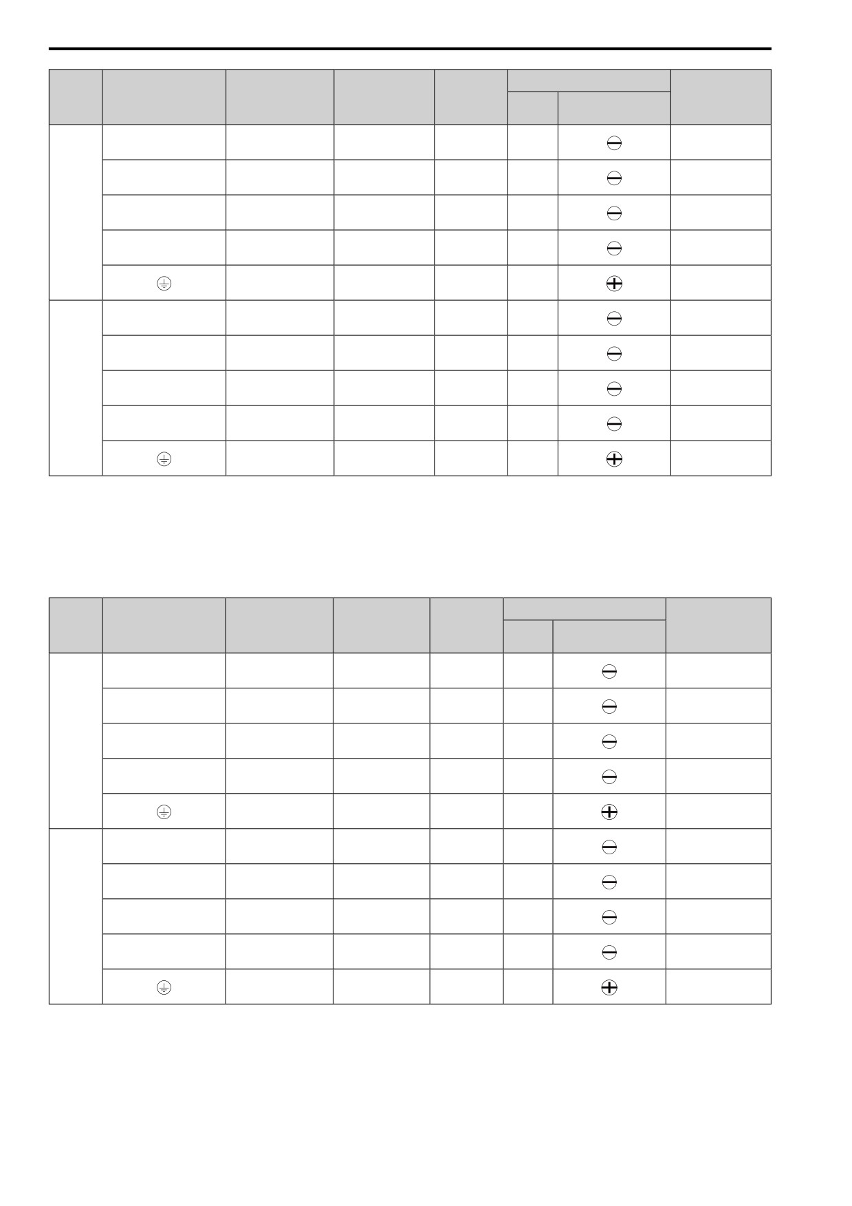
171
5.3 UL Standards
Wire
Terminal Screw
Recommended
Applicable Gauge
Stripping
Tightening Torque
Model
Terminal
Gauge
Length *1
AWG, kcmil
AWG, kcmil
Size
Shape
N∙m (in∙lb)
mm
1.5
- 1.7
L/L1, N/L2
8
14 - 8
10
M4
(13.5 - 15)
1.5
- 1.7
U/T1, V/T2, W/T3
12
14 - 10
10
M4
(13.5 - 15)
1.5
- 1.7
B012
-, +1
8
14 - 8
10
M4
(13.5 - 15)
1.5
- 1.7
B1, B2
14
14 - 12
10
M4
(13.5 - 15)
1.2
- 1.5
10 *2
14 - 10 *2
-
M4
(10.6
- 13.3)
1.5
- 1.7
L/L1, N/L2
8
12 - 6
10
M4
(13.5 - 15)
1.5
- 1.7
U/T1, V/T2, W/T3
10
14 - 8
10
M4
(13.5 - 15)
1.5
- 1.7
B018
-, +1
8
12 - 6
10
M4
(13.5 - 15)
1.5
- 1.7
B1, B2
14
14 - 12
10
M4
(13.5 - 15)
2.0
- 2.5
8 *2
12 - 8 *2
-
M5
(17.7
- 22.1)
*1
Remove insulation from the ends of wires to expose the length of wire shown.
*2
If you turn on the internal EMC filter, the leakage current of the drive will be more than 3.5 mA. Use these closed-loop crimp
terminals or equivalent to connect a protective ground wire that has a minimum cross-sectional area of 10 mm2 (copper wire).
•
8-4NS from JST Mfg. Co., Ltd.
• R8-4S from NICHIFU Co., Ltd.
Three-Phase 400 V Class (UL Compliance)
Wire
Terminal Screw
Recommended
Applicable Gauge
Stripping
Tightening Torque
Model
Terminal
Gauge
Length *1
AWG, kcmil
N∙m (in∙lb)
AWG, kcmil
Size
Shape
mm
0.5
- 0.6
R/L1, S/L2, T/L3
14
14 - 12
8
M3
(4.4
- 5.3)
0.5
- 0.6
U/T1, V/T2, W/T3
14
14 - 12
8
M3
(4.4
- 5.3)
0.5
- 0.6
4001
-, +1, +2
14
14 - 12
8
M3
(4.4
- 5.3)
0.5
- 0.6
B1, B2
14
14 - 12
8
M3
(4.4
- 5.3)
1.2
- 1.5
14 *2
14 - 10 *2
-
M4
(10.6
- 13.3)
0.5
- 0.6
R/L1, S/L2, T/L3
14
14 - 12
8
M3
(4.4
- 5.3)
0.5
- 0.6
U/T1, V/T2, W/T3
14
14 - 12
8
M3
(4.4
- 5.3)
0.5
- 0.6
4002
-, +1, +2
14
14 - 12
8
M3
(4.4
- 5.3)
0.5
- 0.6
B1, B2
14
14 - 12
8
M3
(4.4
- 5.3)
1.2
- 1.5
14 *2
14 - 10 *2
-
M4
(10.6
- 13.3)
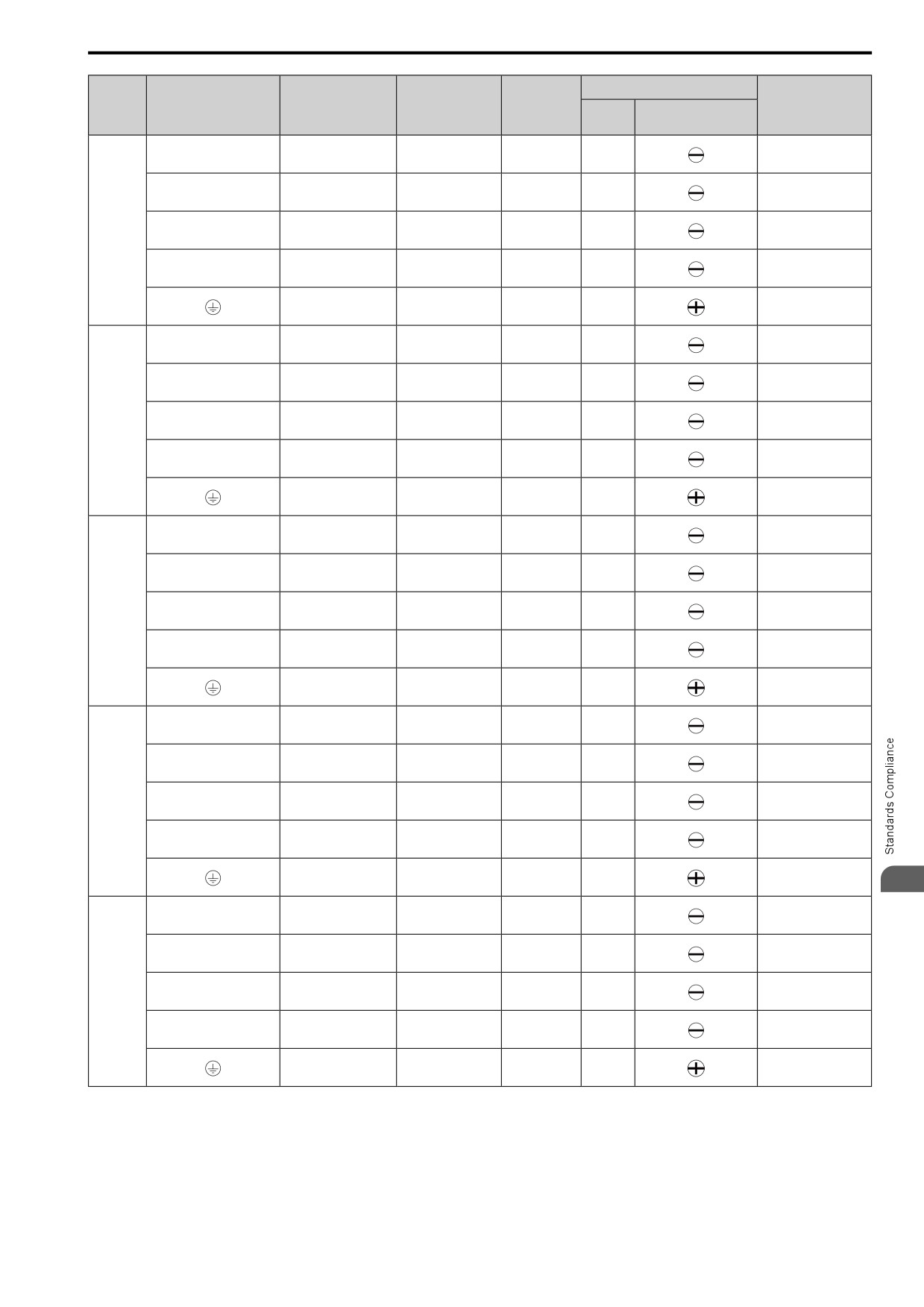
172
5.3
UL Standards
Wire
Terminal Screw
Recommended
Applicable Gauge
Stripping
Tightening Torque
Model
Terminal
Gauge
Length *1
AWG, kcmil
AWG, kcmil
Size
Shape
N∙m (in∙lb)
mm
0.5
- 0.6
R/L1, S/L2, T/L3
14
14 - 12
8
M3
(4.4
- 5.3)
0.5
- 0.6
U/T1, V/T2, W/T3
14
14 - 12
8
M3
(4.4
- 5.3)
0.5
- 0.6
4004
-, +1, +2
14
14 - 12
8
M3
(4.4
- 5.3)
0.5
- 0.6
B1, B2
14
14 - 12
8
M3
(4.4
- 5.3)
1.2
- 1.5
10 *2
14 - 10 *2
-
M4
(10.6
- 13.3)
0.5
- 0.6
R/L1, S/L2, T/L3
14
14 - 12
8
M3
(4.4
- 5.3)
0.5
- 0.6
U/T1, V/T2, W/T3
14
14 - 12
8
M3
(4.4
- 5.3)
0.5
- 0.6
4005
-, +1, +2
14
14 - 12
8
M3
(4.4
- 5.3)
0.5
- 0.6
B1, B2
14
14 - 12
8
M3
(4.4
- 5.3)
1.2
- 1.5
10 *2
14 - 10 *2
-
M4
(10.6
- 13.3)
0.5
- 0.6
R/L1, S/L2, T/L3
14
14 - 12
8
M3
(4.4
- 5.3)
0.5
- 0.6
U/T1, V/T2, W/T3
14
14 - 12
8
M3
(4.4
- 5.3)
0.5
- 0.6
4007
-, +1, +2
14
14 - 12
8
M3
(4.4
- 5.3)
0.5
- 0.6
B1, B2
14
14 - 12
8
M3
(4.4
- 5.3)
1.2
- 1.5
10 *2
14 - 10 *2
-
M4
(10.6
- 13.3)
0.5
- 0.6
R/L1, S/L2, T/L3
14
14 - 12
8
M3
(4.4
- 5.3)
0.5
- 0.6
U/T1, V/T2, W/T3
14
14 - 12
8
M3
(4.4
- 5.3)
0.5
- 0.6
4009
-, +1, +2
14
14 - 12
8
M3
(4.4
- 5.3)
0.5
- 0.6
B1, B2
14
14 - 12
8
M3
(4.4
- 5.3)
1.2
- 1.5
10 *2
14 - 10 *2
-
M4
(10.6
- 13.3)
5
1.5
- 1.7
R/L1, S/L2, T/L3
12
14 - 10
10
M4
(13.5 - 15)
1.5
- 1.7
U/T1, V/T2, W/T3
14
14 - 12
10
M4
(13.5 - 15)
1.5
- 1.7
4012
-, +1, +2
10
12 - 8
10
M4
(13.5 - 15)
1.5
- 1.7
B1, B2
14
14 - 12
10
M4
(13.5 - 15)
1.2
- 1.5
10 *2
14 - 10 *2
-
M4
(10.6
- 13.3)
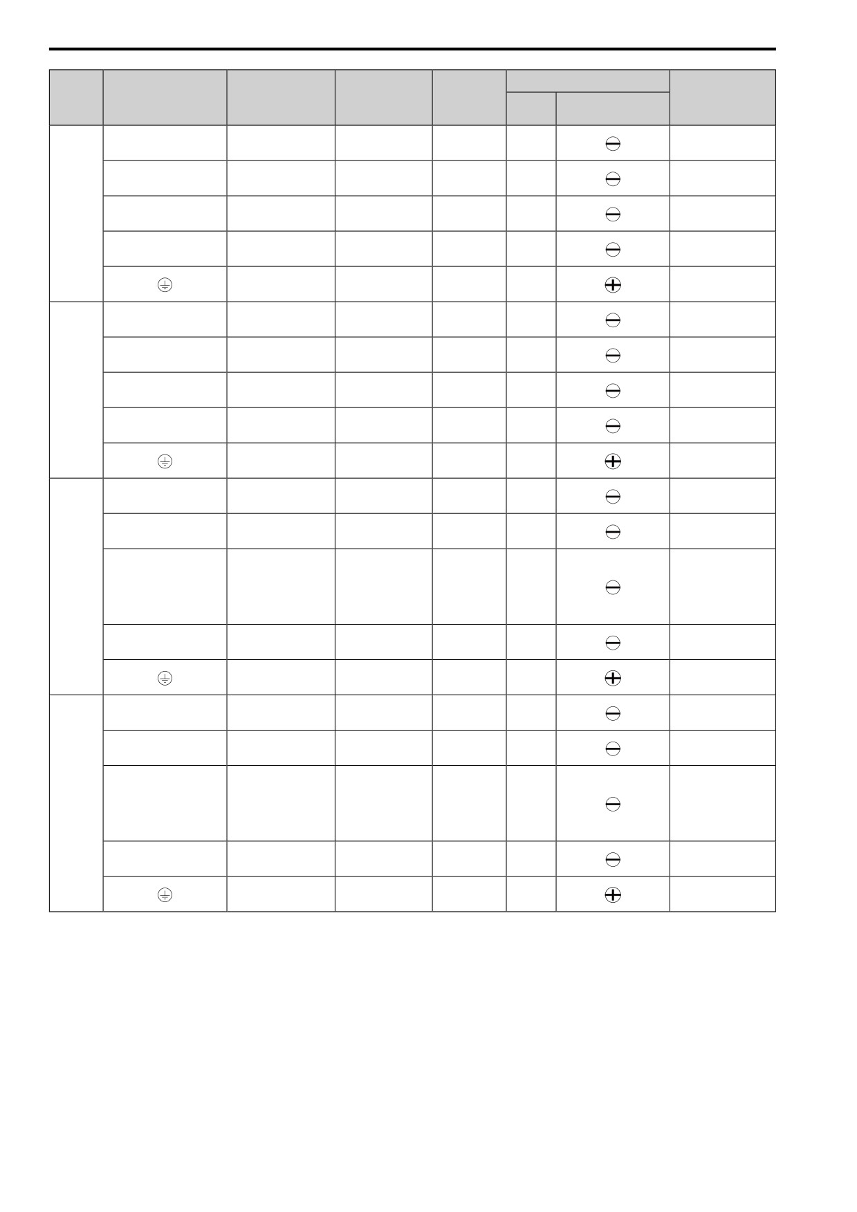
173
5.3 UL Standards
Wire
Terminal Screw
Recommended
Applicable Gauge
Stripping
Tightening Torque
Model
Terminal
Gauge
Length *1
AWG, kcmil
AWG, kcmil
Size
Shape
N∙m (in∙lb)
mm
1.5
- 1.7
R/L1, S/L2, T/L3
10
12 - 8
10
M4
(13.5 - 15)
1.5
- 1.7
U/T1, V/T2, W/T3
10
12 - 8
10
M4
(13.5 - 15)
1.5
- 1.7
4018
-, +1, +2
10
14 - 8
10
M4
(13.5 - 15)
1.5
- 1.7
B1, B2
14
14 - 12
10
M4
(13.5 - 15)
2.0
- 2.5
10 *2
14 - 6 *2
-
M5
(17.7
- 22.1)
1.5
- 1.7
R/L1, S/L2, T/L3
8
14 - 6
10
M4
(13.5 - 15)
1.5
- 1.7
U/T1, V/T2, W/T3
10
14 - 8
10
M4
(13.5 - 15)
1.5
- 1.7
4023
-, +1, +2
8
12 - 6
10
M4
(13.5 - 15)
1.5
- 1.7
B1, B2
12
14 - 10
10
M4
(13.5 - 15)
2.0
- 2.5
10 *2
10 - 6 *2
-
M5
(17.7
- 22.1)
1.5
- 1.7
R/L1, S/L2, T/L3
8
12 - 6
10
M4
(13.5 - 15)
1.5
- 1.7
U/T1, V/T2, W/T3
8
12 - 6
10
M4
(13.5 - 15)
•
≤ AWG 10
2.3
- 2.5
(19.8 - 22)
4031
-, +1, +2
6
12 - 4
18
M5
•
AWG 8 ≤
4.1
- 4.5
(36 - 40)
1.5
- 1.7
B1, B2
10
12 - 8
10
M4
(13.5 - 15)
5.4
- 6.0
8
10 - 6
-
M6
(47.8
- 53.1)
1.5
- 1.7
R/L1, S/L2, T/L3
6
12 - 6
10
M4
(13.5 - 15)
1.5
- 1.7
U/T1, V/T2, W/T3
8
12 - 6
10
M4
(13.5 - 15)
•
≤ AWG 10
2.3
- 2.5
(19.8 - 22)
4038
-, +1, +2
4
10 - 2
18
M5
•
AWG 8 ≤
4.1
- 4.5
(36 - 40)
1.5
- 1.7
B1, B2
10
14 - 6
10
M4
(13.5 - 15)
5.4
- 6.0
6
10 - 6
-
M6
(47.8
- 53.1)
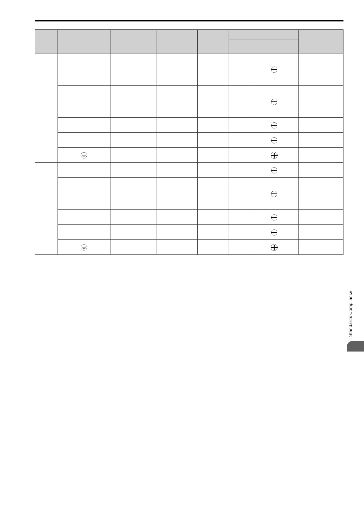
174
5.3 UL Standards
Wire
Terminal Screw
Recommended
Applicable Gauge
Stripping
Tightening Torque
Model
Terminal
Gauge
Length *1
AWG, kcmil
AWG, kcmil
Size
Shape
N∙m (in∙lb)
mm
•
≤ AWG 10
2.3
- 2.5
(19.8 - 22)
R/L1, S/L2, T/L3
4
10 - 2
18
M5
•
AWG 8 ≤
4.1
- 4.5
(36 - 40)
•
≤ AWG 10
2.3
- 2.5
(19.8 - 22)
U/T1, V/T2, W/T3
6
12 - 4
18
M5
•
AWG 8 ≤
4044
4.1
- 4.5
(36 - 40)
4.1
- 4.5
-, +1, +2
2
8-2
18
M5
(36 - 40)
1.5
- 1.7
B1, B2
8
12 - 6
10
M4
(13.5 - 15)
5.4
- 6.0
6
10 - 6
-
M6
(47.8
- 53.1)
4.1
- 4.5
R/L1, S/L2, T/L3
2
8-2
18
M5
(36 - 40)
•
≤ AWG 10
2.3
- 2.5
(19.8 - 22)
U/T1, V/T2, W/T3
4
10 - 2
18
M5
•
AWG 8 ≤
4.1
- 4.5
(36 - 40)
4060
4.1
- 4.5
-, +1, +2
2
6-2
18
M5
(36 - 40)
1.5
- 1.7
B1, B2
8
12 - 6
10
M4
(13.5 - 15)
5.4
- 6.0
6
10 - 6
-
M6
(47.8
- 53.1)
*1
Remove insulation from the ends of wires to expose the length of wire shown.
*2
If you turn on the internal EMC filter, the leakage current of the drive will be more than 3.5 mA. Use these closed-loop crimp
terminals or equivalent to connect a protective ground wire that has a minimum cross-sectional area of 10 mm2 (copper wire).
•
8-4NS from JST Mfg. Co., Ltd.
• R8-4S from NICHIFU Co.,Ltd.
■ Factory-Recommended Branch Circuit Protection for UL Listing
Use branch circuit protection to protect against short circuits and to maintain compliance with UL61800-5-1. The
manufacturer recommends connecting semiconductor protection fuses on the input side for branch circuit
protection.
WARNING! Electrical Shock Hazard. After the drive blows a fuse or trips an RCM/RCD, do not immediately energize the drive
or operate peripheral devices. Wait for the time specified on the warning label at a minimum and make sure that all indicators
5
are OFF. Then check the wiring and peripheral device ratings to find the cause of the problem. If you do not know the cause of
the problem, contact the manufacturer before you energize the drive or peripheral devices. If you do not fix the problem before
you operate the drive or peripheral devices, it can cause serious injury or death.
•
200 V class
Use the fuses specified in this document to prepare the drive for use on a circuit that supplies not more than
31,000 RMS and not more than 240 Vac when there is a short circuit in the power supply.
•
400 V class
Use the fuses specified in this document to prepare the drive for use on a circuit that supplies not more than
31,000 RMS and not more than 480 Vac when there is a short circuit in the power supply.
The built-in short circuit protection of the drive does not provide branch circuit protection. The user must provide
branch circuit protection as specified by the National Electric Code (NEC), the Canadian Electric Code, Part I
(CEC), and local codes.
175
5.3 UL Standards
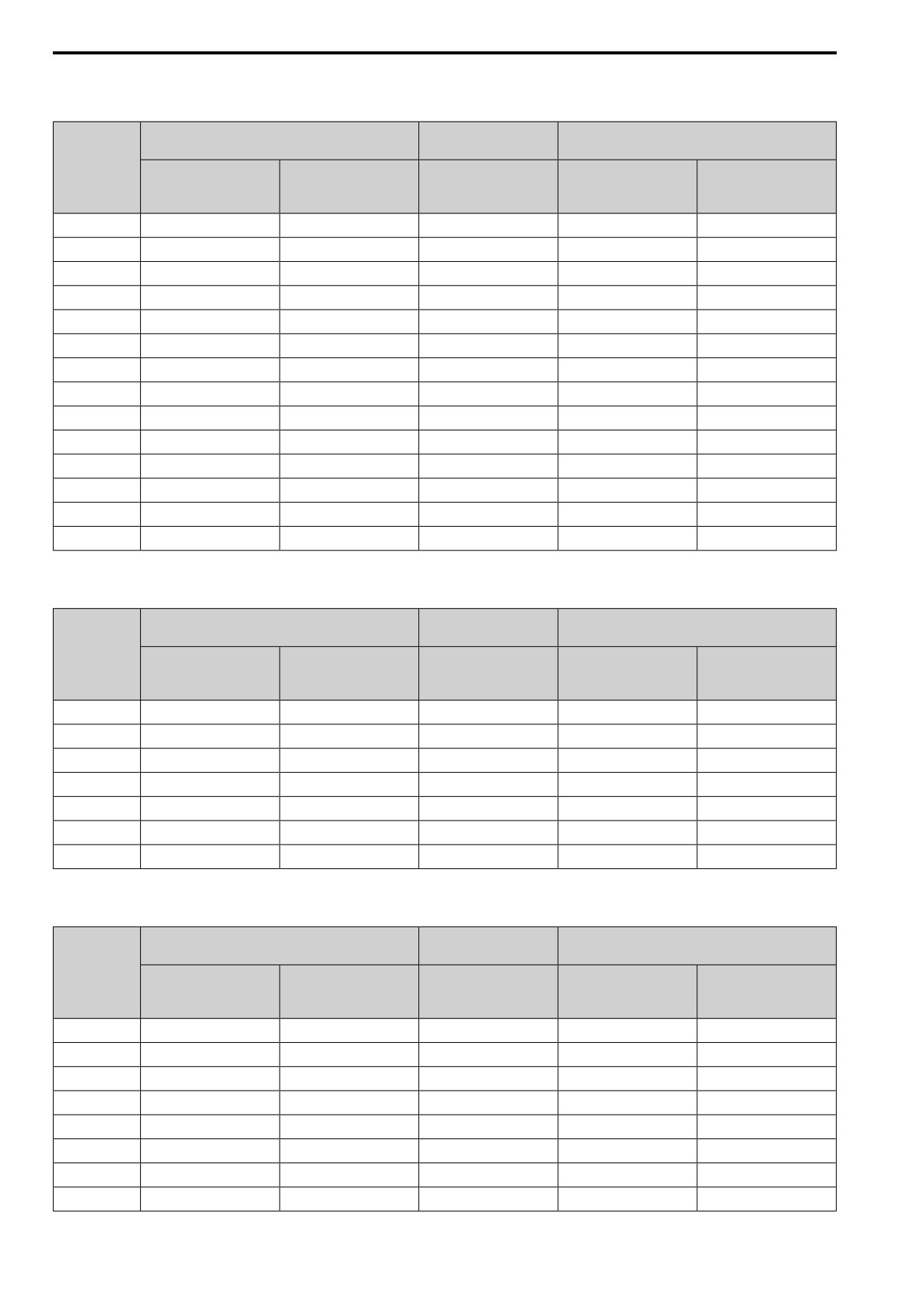
Three-Phase 200 V Class
Table 5.15 Factory-Recommended Branch Circuit Protection: Three-Phase 200 V Class
Maximum Applicable Motor Output
Semiconductor Protection Fuse Rated Current
Time Delay Fuse
kW (HP)
Manufacturer: EATON/Bussmann
Drive Model
Class J, CC, and T Fuse
Input Rated Current
ND
HD
Rated Current
Model
A
A
2001
0.18
(1/6)
0.1
(1/6)
3
FWH-25A14F
25
2002
0.37
(1/4)
0.25
(1/4)
6
FWH-25A14F
25
2004
0.75
(3/4)
0.55
(1/2)
6
FWH-25A14F
25
2006
1.1
(1.5)
0.75
(1)
10
FWH-25A14F
25
2008
1.5
(2)
1.1
(1.5)
15
FWH-70B
70
2010
2.2
(3)
1.5
(2)
20
FWH-70B
70
2012
3.0
(4)
2.2
(3)
25
FWH-70B
70
2018
3.7
(5)
3.0
(4)
30
FWH-90B
90
2021
5.5
(5)
4.0
(5)
40
FWH-90B
90
2030
7.5
(10)
5.5
(7.5)
-
FWH-100B
100
2042
11
(15)
7.5
(10)
-
FWH-150B
150
2056
15
(20)
11
(15)
-
FWH-200B
200
2070
18.5
(25)
15
(20)
-
FWH-200B
200
2082
22
(30)
18.5
(25)
-
FWH-225A
225
Single-Phase 200 V Class
Table 5.16 Factory-Recommended Branch Circuit Protection: Single-Phase 200 V Class
Maximum Applicable Motor Output
Semiconductor Protection Fuse Rated Current
Time Delay Fuse
kW (HP)
Manufacturer: EATON/Bussmann
Drive Model
Class J, T, and CC Fuse
Input Rated Current
ND
HD
Rated Current
Model
A
A
B001
0.18
(1/6)
0.1
(1/6)
3
FWH-25A14F
25
B002
0.37
(1/4)
0.25
(1/4)
6
FWH-25A14F
25
B004
0.75
(3/4)
0.55
(1/2)
10
FWH-60B
60
B006
1.1
(1.5)
1.1
(1)
15
FWH-80B
80
B010
2.2
(3)
1.5
(2)
25
FWH-100B
100
B012
3.0
(3)
2.2
(3)
30
FWH-125B
125
B018
-
4.0
(5)
-
FWH-150B
150
Three-Phase 400 V Class
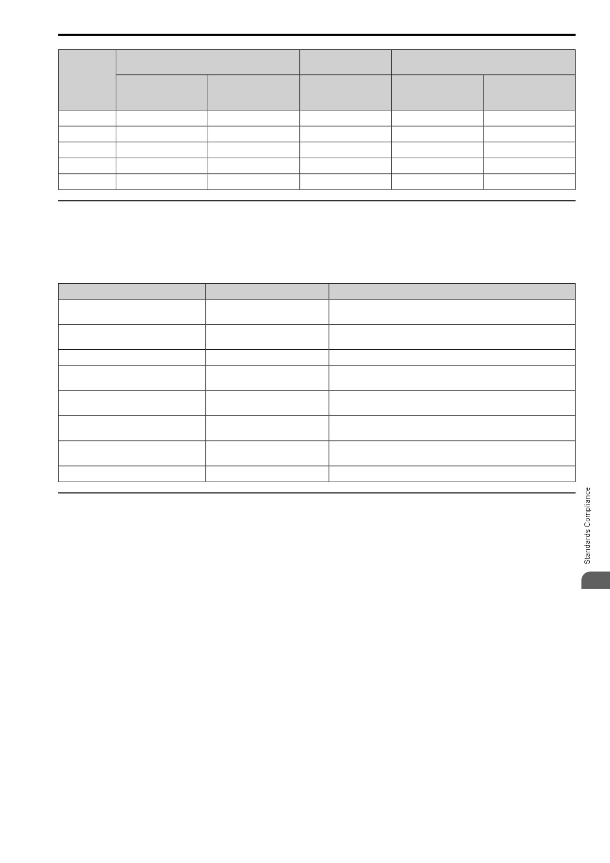
Table 5.17 Factory-Recommended Branch Circuit Protection: Three-Phase 400 V Class
Maximum Applicable Motor Output
Semiconductor Protection Fuse Rated Current
Time Delay Fuse
kW (HP)
Manufacturer: EATON/Bussmann
Drive Model
Class J, CC, and T Fuse
Input Rated Current
ND
HD
Rated Current
Model
A
A
4001
0.37
(1/2)
0.37
(1/2)
3
FWH-40B
40
4002
0.75
(1)
0.55
(3/4)
6
FWH-40B
40
4004
1.5
(2)
1.1
(2)
10
FWH-50B
50
4005
2.2
(3)
1.5
(3)
10
FWH-70B
70
4007
3.0
(4)
2.2
(3)
15
FWH-70B
70
4009
4.0
(5)
3.0
(4)
20
FWH-90B
90
4012
5.5
(7.5)
4.0
(5)
25
FWH-90B
90
4018
7.5
(10)
5.5
(10)
-
FWH-80B
80
176
5.3 UL Standards
Maximum Applicable Motor Output
Semiconductor Protection Fuse Rated Current
Time Delay Fuse
kW (HP)
Manufacturer: EATON/Bussmann
Drive Model
Class J, CC, and T Fuse
Input Rated Current
ND
HD
Rated Current
Model
A
A
4023
11.0
(15)
7.5
(10)
-
FWH-100B
100
4031
15.0
(20)
11.0
(15)
-
FWH-125B
125
4038
18.5
(25)
15.0
(20)
-
FWH-175B
175
4044
22.0
(30)
18.5
(25)
-
FWH-200B
200
4060
30.0
(40)
22.0
(30)
-
FWH-200B
200
◆ Low Voltage Wiring for Control Circuit Terminals
You must provide low voltage wiring as specified by the National Electric Code (NEC), the Canadian Electric
Code, Part I (CEC), and local codes. The manufacturer recommends the NEC class 1 circuit conductor. Use the
UL approved class 2 power supply for external power supply.
Table 5.18 Control Circuit Terminal Power Supplies
Input/Output
Terminals
Power Supply Specifications
Uses the LVLC power supply in the drive.
Digital input
DI1 to DI7, D0V, DIC, D24V
Use the UL Listed class 2 power supply for external power supply.
Uses the LVLC power supply in the drive.
Analog input
AI1, AI2, A0V ,+10V
Use the UL Listed class 2 power supply for external power supply.
Analog output
AO, A0V
Uses the LVLC power supply in the drive.
Uses the LVLC power supply in the drive.
Pulse train output
PO, A0V
Use the UL Listed class 2 power supply for external power supply.
Uses the LVLC power supply in the drive.
Pulse Train Input
PI, A0V
Use the UL Listed class 2 power supply for external power supply.
Uses the LVLC power supply in the drive.
Safe disable input
H1, H2, HC
Use the UL Listed class 2 power supply for external power supply.
Uses the LVLC power supply in the drive.
Serial communication input/output
RS485+, RS485-, A0V
Use the UL Listed class 2 power supply for external power supply.
24 V external power supply
E24V, A0V
Use the UL Listed class 2 power supply.
◆ Drive Motor Overload and Overheat Protection
The drive motor overload and overheat protection function complies with the National Electric Code (NEC) and
the Canadian Electric Code, Part I (CEC).
Set the Motor Rated Current and L1-01 through L1-04 [Motor Overload Protection Select] correctly to enable
motor overload and overheat protection.
Refer to the control method and set the motor rated current with E2-01 [Mot Rated Current (FLA)], E5-03 [PM
5
Mot Rated Current (FLA)], or E9-06 [Motor Rated Current].
177
5.4 对应中国RoHS指令
5.4
对应中国RoHS指令
15
图 5.18 中国RoHS标志
中国RoHS标志依据2016年1月26日公布的《电器电子产品有害物质限制使用管理办法》,以及《电子电气产品有
害物质限制使用标识要求》(SJ/T 11364-2014)作成。电子电气产品中特定6种有害物质的含量超过规定值时,应
标识此标志。中间的数字为在中国生产销售以及进口的电子电气产品的环保使用期限(年限)。电子电气产品的环
保使用期限从生产日期算起。在期限内,正常使用产品的过程中,不会有特定的6种有害物质外泄进而对环境、人
和财产造成深刻影响。
本产品的环保使用期限为15年。但需要注意的是环保使用期限并非产品的质量保证期限。
◆ 本产品中含有有害物质的信息
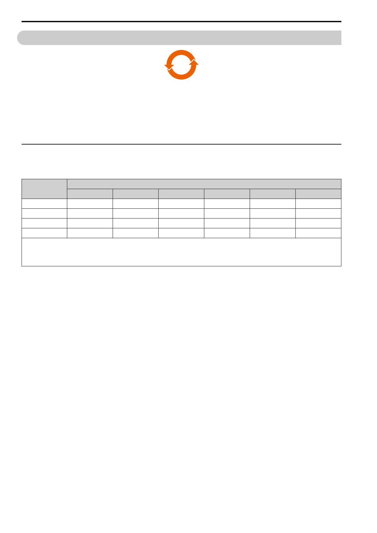
本产品中所含有害物质的详细信息如表 5.19所示。
表 5.19 本产品中有害物质的名称及含量
有害物质
部件名称
铅(Pb)
汞(Hg)
镉(Cd)
六价铬(Cr(VI))
多溴联苯(PBB)
多溴二苯醚(PBDE)
实装基板
×
○
○
○
○
○
电子元件
×
○
○
○
○
○
黄铜螺钉
×
○
○
○
○
○
铝压铸
×
○
○
○
○
○
本表格依据SJ/T 11364的规定编制。
○:表示该有害物质在该部件所有均质材料中的含量均在GB/T 26572规定的限量要求以下。
×:表示该有害物质至少在该部件的某一均质材料中的含量超出GB/T 26572规定的限量要求。
(注) 本产品符合欧盟RoHS指令。上表中的“×”表示含有欧盟RoHS指令豁免的有害物质。
178
5.5 China RoHS Compliance
5.5
China RoHS Compliance
15
Figure 5.19 China RoHS Mark
The China RoHS mark is displayed on products containing six specified hazardous substances that are in excess
of regulatory limits, based on the “Administrative Measures for the Restriction of the Use of Hazardous
Substances in Electrical and Electronic Products” and “Marking for the Restricted Use of Hazardous Substances in
Electronic and Electrical Products” (SJ/T 11364-2014), which were promulgated on January 26, 2016. The
number displayed in the center of the mark indicates the environment-friendly use period (number of years) in
which electrical and electronic products that are being produced, sold, or imported to China can be used. The date
of manufacture of the electrical and electronic product is the starting date of the environment-friendly use period
for the product. The six specified hazardous substances contained in the product will not leak outside of the
product during normal use within this period and will have no serious impact on the environment, the human
body, or property.
The environment-friendly use period for this product is 15 years. This period is not the product warranty period.
◆ Information on Hazardous Substances in This Product
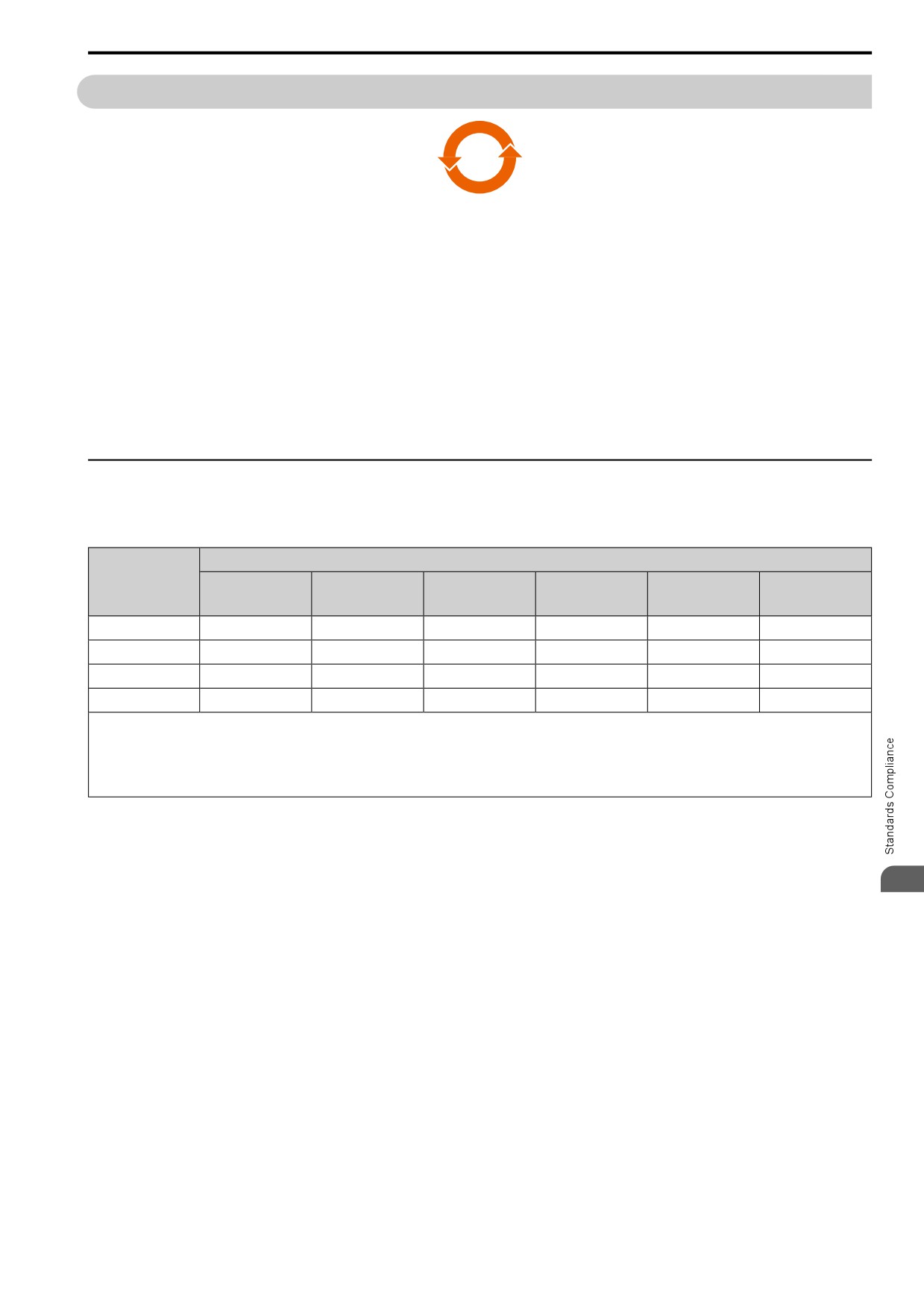
Table 5.20 shows the details on hazardous substances contained in this product.
Table 5.20 Contents of Hazardous Substances in This Product
Hazardous Substances
Parts Name
Polybrominated
Hexavalent
Polybrominated
Lead (Pb)
Mercury (Hg)
Cadmium (Cd)
Diphenyl Ethers
Chromium (Cr(VI))
Biphenyls (PBB)
(PBDE)
Circuit Board
×
○
○
○
○
○
Electronic Parts
×
○
○
○
○
○
Brass Screw
×
○
○
○
○
○
Aluminum Die Casting
×
○
○
○
○
○
This table has been prepared in accordance with the provisions outlined in SJ/T 11364.
○: Indicates that said hazardous substance contained in all of the homogeneous materials for this part is below or equal to the limit requirement of GB/T 26572.
×: Indicates that said hazardous substance contained in at least one of the homogeneous materials used for this part is above the limit requirement of GB/T 26572.
Note:
This product complies with EU RoHS directives. In this table, "×" indicates that hazardous substances that are exempt from EU RoHS directives are contained.
5
179
5.6 Safe Disable Input
5.6
Safe Disable Input
This section gives precautions to support the Safe Disable input. Contact the manufacturer for more information.
Figure 5.20 TUV Mark
The TUV mark identifies that the product complies with the safety standards.
The safety function complies with the following standards.
Table 5.21 Applied Safety Standards and Unified Standards
Safety Standards
Unified Standards
IEC/EN 61508:2010 (SIL3)
IEC 62061:2005/AMD2:2015 (SILCL3)
Functional Safety
EN 62061:2005/A2:2015 (SILCL3)
IEC 61800-5-2:2016 (SIL3)
EN 61800-5-2:2017 (SIL3)
Machine Safety
ISO/EN ISO 13849-1:2015 (Cat.3, PL e)
IEC 61000-6-7:2014
EMC
EN 61000-6-7:2015
IEC/EN 61326-3-1:2017
IEC 61800-5-1:2007/AMD1:2016
LVD
EN 61800-5-1:2007/A1:2017
Note:
SIL = Safety Integrity Level.
◆ Safe Disable Specifications
The Safe Disable input provides the stop function that complies with “Safe Torque Off” as specified by IEC/EN
61800-5-2. The Safe Disable input meets the requirements of ISO/EN ISO 13849-1 and IEC/EN 61508. It also has
a safety status monitor to detect safety circuit errors.
When you install the drive as a component in a system, you must make sure that the system complies with the
applicable safety standards.
Table 5.22 Safe Disable Specifications
Item
Description
• Input: 2
Safe Disable input (H1, H2)
Signal ON level: 18 Vdc to 28 Vdc
Input/Output
Signal OFF level: -4 Vdc to +4 Vdc
• Output: 1
MFDO safety monitor output for external device monitor (EDM)
Response time from when the input opens to when the drive output stops
3 ms or less
Response time from when the H1 and H2 terminal inputs open to when the EDM signal
30 ms or less
operates
Failure probability in Less frequent operation request mode
PFD = 1.38E-5
Failure probability in Frequent operation request mode or continuous mode
PFH = 3.35E-9
The Safe Disable input complies with the performance level requirements of EN ISO
Performance level
13849-1.
HFT (hardware fault tolerance)
N=1
Type of subsystem
Type B
MTTFD
High
DCavg
Medium
Mission time
10 years
EDM = External Device Monitoring
PFD = Probability of Failure on Demand
180
5.6 Safe Disable Input
PFH = Probability of Dangerous Failure per Hour
◆ Safety Precautions
DANGER! Sudden Movement Hazard. When you use the Safe Disable function in the safety system of a machine, do a full risk
assessment for the system to make sure that all parts of the system comply with applicable safety standards. Incorrect
application of the Safe Disable function can cause serious injury or death.
DANGER! Sudden Movement Hazard. If the output circuit of the drive is damaged and the Safe Disable function turns OFF the
drive output to a permanent magnet (PM) motor, the motor can rotate 180 electrical degrees. Prevent damage to equipment and
injury to personnel during this condition. Sudden motor movement can cause serious injury or death. It is possible for current to
flow through the motor winding in these conditions.
DANGER! Electrical Shock Hazard. You cannot depend on the Safe Disable function to prevent electrical shock. Disconnect all
power to the drive and wait for the time specified on the warning label before you remove covers. Check the drive for dangerous
voltages before servicing or repair work. If you do work on the drive when it is energized and there is no cover over the
electronic circuits, it can cause serious injury or death.
WARNING! Sudden Movement Hazard. Although the Safe Disable function is in operation, gravity or other external forces in the
vertical axis can move the motor. Incorrect application of the Safe Disable function can cause serious injury or death.
WARNING! Sudden Movement Hazard. Do not use the drive output signals to control external holding brakes or dynamic
brakes for functional safety. Use a system that conforms to the functional safety requirements. Incorrect application of the Safe
Disable function can cause serious injury or death. Systems that use drive output signals (including EDM) for safety are not safe
because drive output signals are not safety components.
WARNING! Sudden Movement Hazard. Connect the Safe Disable inputs to the devices as specified by the safety requirements.
If you connect the Safe Disable inputs incorrectly, it can cause serious injury or death.
WARNING! Sudden Movement Hazard. To use the Safe Disable inputs, remove the jumpers between terminals H1-HC and H2-
HC. If the Safe Disable circuit does not work correctly, it can cause serious injury or death.
WARNING! Sudden Movement Hazard. When you clear the Safe Disable input, make sure that the Safe Disable Monitor output
operates correctly as the specification for Safe Disable function. If the Safe Disable circuit does not operate correctly, it can
cause serious injury or death.
WARNING! Sudden Movement Hazard. Regularly examine the Safe Disable input and all other safety features. A system that
does not operate correctly can cause serious injury or death.
WARNING! Sudden Movement Hazard. Only let approved personnel who know about the drive, instruction manual, and safety
standards wire, examine, and maintain the Safe Disable input. If personnel are not approved, it can cause serious injury or
death.
WARNING! Sudden Movement Hazard. Only use the Safe Disable Monitor (multi-function output terminal set to the EDM
function) to monitor the Safe Disable status or to find a malfunction in the Safe Disable inputs. The monitor output is not a safety
output. If you use the Safe Disable Monitor incorrectly, it can cause death or serious injury.
Note:
• When you use a drive with a built in safety function, you must replace it 10 years after first use.
•A maximum of 3 ms will elapse from when terminals H1 or H2 shut off until the drive switches to the “Safe Torque Off” status. Set the
OFF status for terminals H1 and H2 to hold for at least 3 ms. The drive may not be able to switch to the “Safe Torque Off” status if
terminals H1 and H2 are only open for less than 3 ms.
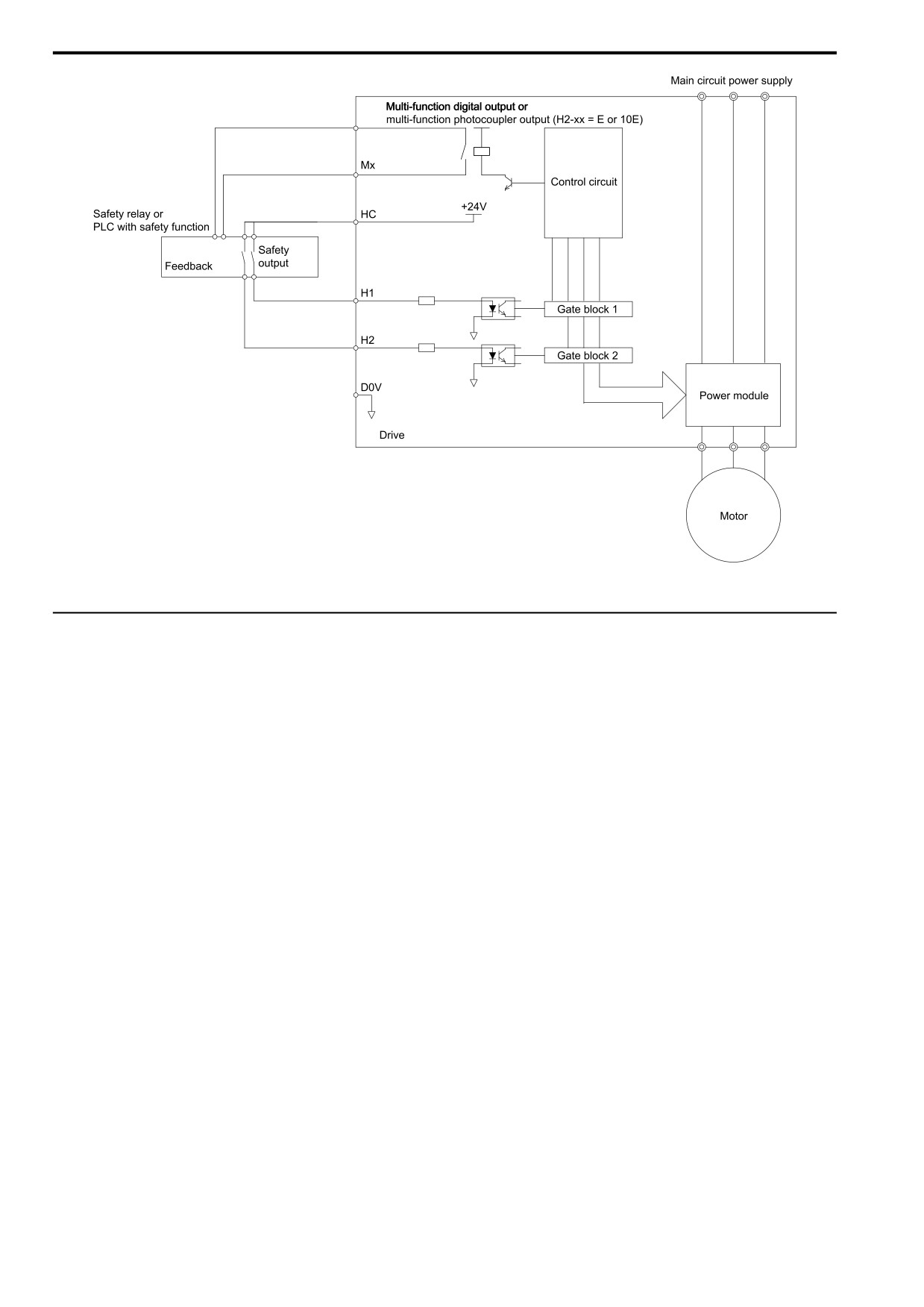
◆ Safe Disable Circuit
The Safe Disable circuit has two isolated channels (terminals H1 and H2) that stop the output transistors. The
input can use the internal power supply of the drive.
Set the EDM function to one of the MFDO terminals [H2-xx = E or 10E] to monitor the status of the Safe Disable
5
function. This is the “Safe Disable monitor output function”.
181
5.6 Safe Disable Input
multi-function photocoupler output (H2-xx = 21 or 121)
Figure 5.21 Safe Disable Function Wiring Example
◆ Connect Safe Disable Input Contacts to Multiple Drives
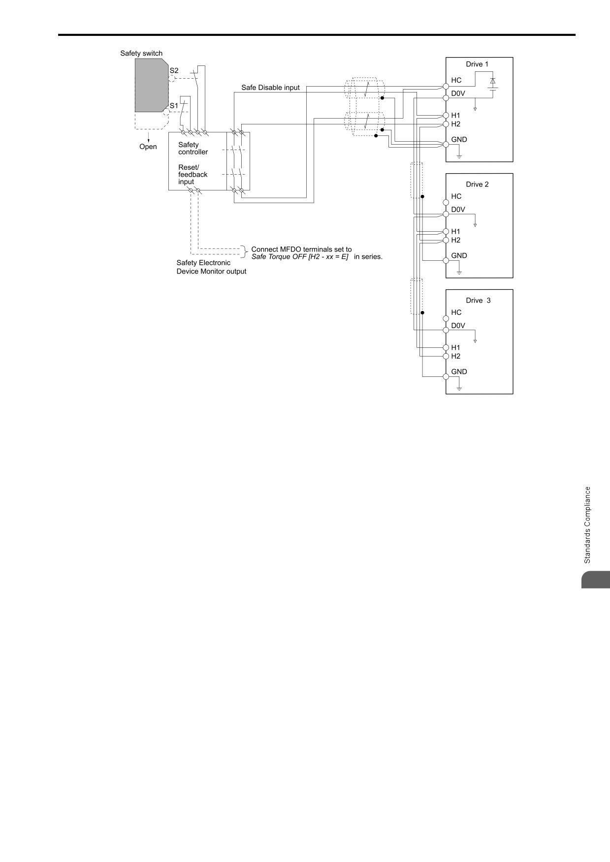
■ To Use the Drive Internal Power Supply
From the terminals HC-SN of drive 1, supply the power for the Safe Disable function for the applicable drives.
These conditions limit the number of units to connect:
• Internal power supply capacity
• Number of MFDIs used
• Supply current to the external sensors
182
5.6 Safe Disable Input
Figure 5.22 Connection Example to Use the Internal Power Supply
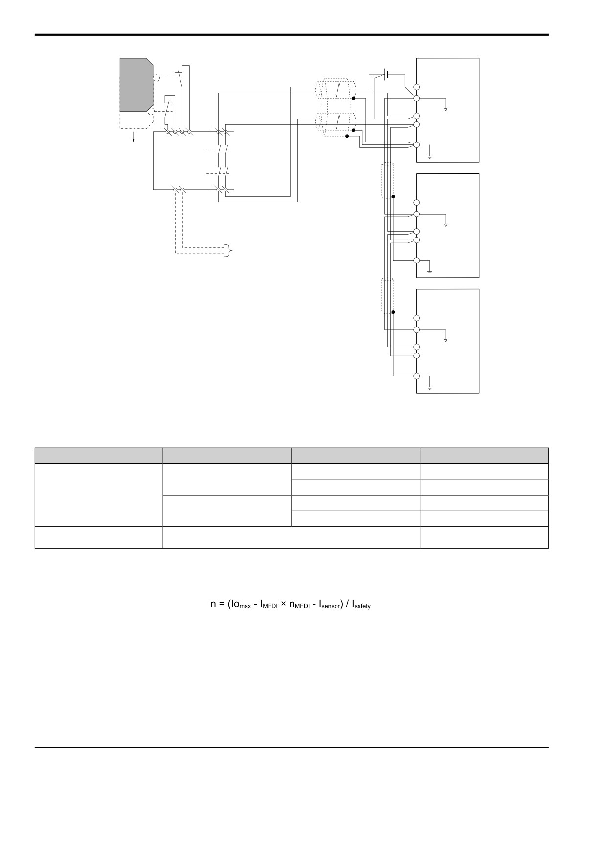
■ To Use 24 V External Power Supply
These conditions limit the number of units to connect:
• External power supply capacity
• Number of MFDIs used
• Supply current to the external sensors
5
183
5.6
Safe Disable Input
Safety switch
S2
Drive 1
HC
Safe Disable input
D0V
S1
H1
H2
Safety
GND
Open
controller
Reset/
feedback
input
Drive 2
HC
D0V
H1
H2
Connect MFDO terminals set to
Safe Torque OFF [H2 - xx = E] in series.
GND
Safety Electronic
Device Monitor output
Drive 3
HC
D0V
H1
H2
GND
Figure 5.23 Connection Example to Use 24 V External Power Supply
■ Number of possible units to connect
Power Supply
Digital Inputs
24 V Output
Number of Drive Units
Yes *1
1
Yes
(7-channel input)
Internal power supply
No
13
(Drive 1)
Yes *1
4
No
No
17
Different for different external power
External power supply
-
supply capacities *2
*1
This is when you use a maximum of 150 mA.
*2
24 V, 12 mA is necessary for each drive.
Use this formula to calculate the number of units to connect:
• n: Number of units to connect
• Iomax: Maximum current that the power supply can supply (234 mA for the internal power supply)
• IMFDI: Current consumed per MFDI (6 mA)
• nMFDI: Maximum number of MFDIs that can be activated at the same time (maximum of 7-channel)
• Isensor: Current externally supplied for sensor power supply (maximum of 150 mA)
• Isafety: Current consumed by Safe Disable terminals H1 and H2 (12 mA)
Note:
Round the values to the first decimal place.
◆ Enabling and Disabling the Drive Output (“Safe Torque Off”)
This is an example of drive operation when as the drive changes from the "Safe Torque Off" status to usual
operation.
184
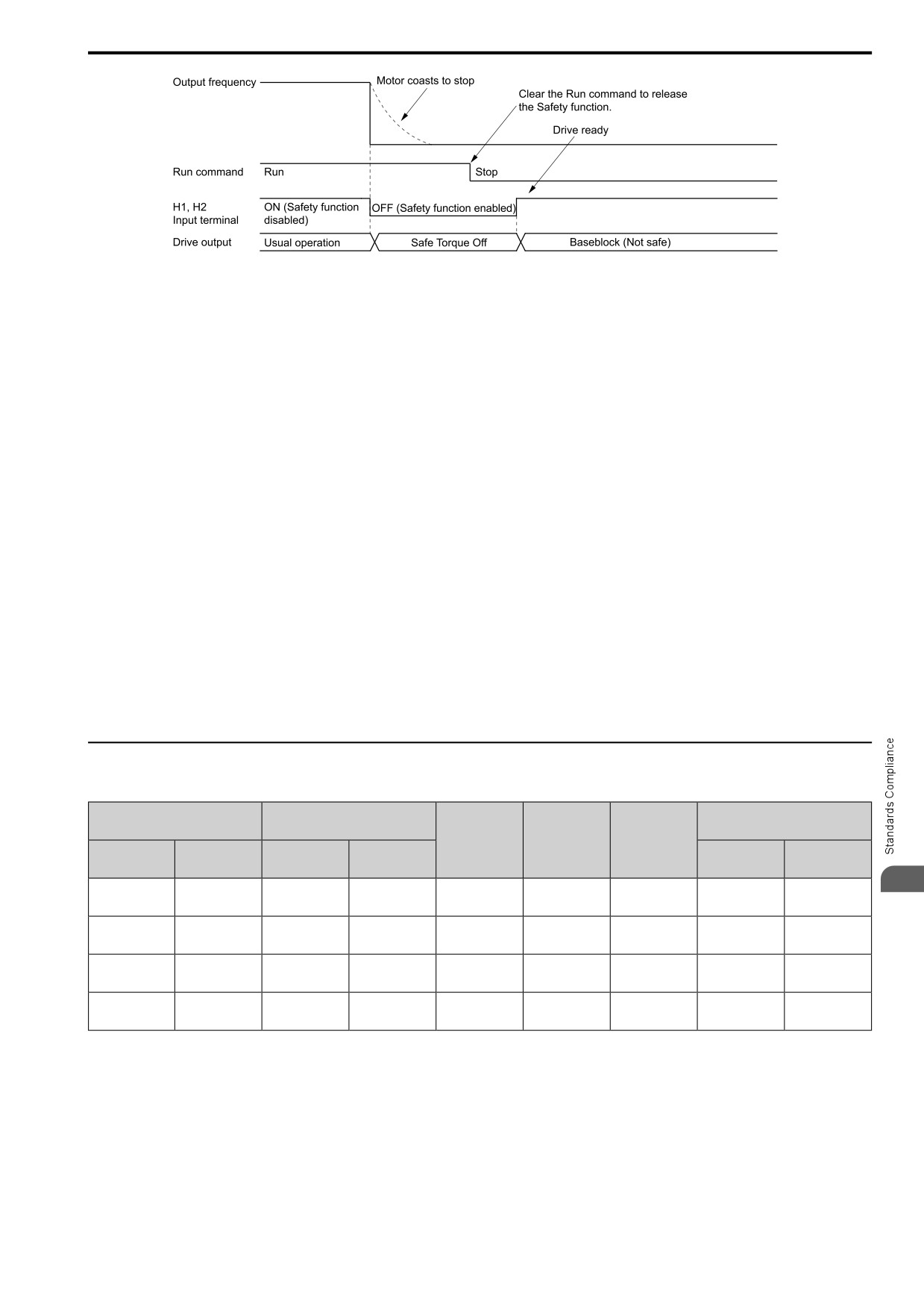
5.6 Safe Disable Input
Figure 5.24 Safe Disable Operation
■ Switching from Usual Operation to “Safe Torque Off”
Turn OFF (open) safety input terminal H1 or H2 to enable the Safe Disable function. When the Safe Disable
function is enabled while the motor is operating, the drive output and motor torque turn off and the motor always
coasts to stop. The b1-03 [Stopping Method Selection] setting does not have an effect on the stopping method.
The “Safe Torque Off” status is only possible with the Safe Disable function. Clear the Run command to stop the
drive. Turning off drive output (a baseblock condition) ≠ “Safe Torque Off”.
Note:
• When it is necessary to ramp to stop the motor, do not turn off terminals H1 and H2 until the motor fully stops. This will prevent the
motor from coasting to stop during usual operation.
•A maximum of 3 ms will elapse from when terminals H1 or H2 shut off until the drive switches to the "Safe Torque Off" status. Set the
OFF status for terminals H1 and H2 to hold for at least 3 ms. The drive may not be able to switch to the “Safe Torque Off” status if
terminals H1 and H2 are only open for less than 3 ms.
■ Going from “Safe Torque Off” to Usual Operation
The safety input will only release when there is no Run command.
• During Stop
When the Safe Disable function is triggered during stop, close the circuit between terminals H1-HC and H2-HC
to disable “Safe Torque Off”. Enter the Run command after the drive stops correctly.
• During Run
When the Safe Disable function is triggered during run, close the circuit between terminals H1-HC and H2-HC
to disable “Safe Torque Off” after clearing the Run command. Enter the Stop command, then enter the Run
command when terminals H1 and H2 are ON or OFF.
◆ Safe Disable Monitor Output Function and Keypad Display
Table 5.23 Safe Disable Input and External Device Monitor (EDM) Terminal Status
Modbus Register
Input Channel Status
Safety Monitor Output Status
0020H
Drive Output
Keypad
READY LED
Status
Display
Input 1
Input 2
MFDO Terminal
MFDO Terminal
bit C
bit D
(H1-HC)
(H2-HC)
(H2-xx = E)
(H2-xx = 10E)
5
ON
ON
Baseblock
Normally
READY:
OFF
ON
0
0
(Close the circuit)
(Close the circuit)
(Drive ready)
displayed
Illuminated
OFF
ON
Safety status
SToF
ALM/ERR:
OFF
ON
1
0
(Open)
(Close the circuit)
(STo)
(Flashing)
Flashing
ON
OFF
Safety status
SToF
ALM/ERR:
OFF
ON
1
0
(Close the circuit)
(Open)
(STo)
(Flashing)
Flashing
OFF
OFF
Safety status
STo
ON
OFF
READY: Flashing
0
1
(Open)
(Open)
(STo)
(Flashing)
■ Safety Function Status Monitor
The drive Safety monitor output sends a feedback signal about the status of the Safety function. The Safety
monitor output is one of the possible settings available for the MFDO terminals. If there is damage to the Safe
Disable circuit, a controller (PLC or safety relay) must read this signal as an input signal to hold the “Safe Torque
Off” status. This will help verify the condition of the safety circuit. Refer to the manual for the safety device for
more information about the Safety function.
It is possible to switch polarity of the Safety monitor output signal with the MFDO function settings. Refer to
Table 5.23 for setting instructions.
185
5.6 Safe Disable Input
■ Keypad Display
If the two input channels are OFF (Open), the keypad will flash STo [Safe Torque OFF].
If there is damage to the Safe disable circuit or the drive, the keypad will flash SToF [Safe Torque OFF
Hardware] when one input channel is OFF (Open), and the other is ON (Short circuit). When you use the Safe
disable circuit correctly, the keypad will not show SToF.
If there is damage to the drive, the keypad will show SCF [Safety Circuit Fault] when the drive detects a fault in
the Safe disable circuit. Refer to the chapter on Troubleshooting for more information.
◆ Validating the Safe Disable Function
After you replace parts or do maintenance on the drive, complete all necessary wiring to start the drive, then
follow these steps to test the Safe Disable input. Keep a record of the test results.
1. When the two input channels are OFF (Open), make sure that the keypad flashes STo [Safe Torque OFF], and
make sure that the motor is not running.
2. Monitor the ON/OFF status of the input channels and make sure that MFDO set to the EDM function operates
as shown in Table 5.23.
If one or more of the these items are true, the ON/OFF status of the MFDO may not display correctly on the
keypad.
• Incorrect parameter settings.
• A problem with an external device.
• The external wiring has a short circuit or is disconnected.
• There is damage to the device.
Find the cause and repair the problem to correctly display the status.
3. Make sure that the EDM signal operates during usual operation as shown in Table 5.23.
186
6
Network Communications
6.1
Safety Precautions
188
6.2
Field Bus Network Support
189
6.3
Modbus Communications
190
187
6.1 Safety Precautions
6.1
Safety Precautions
DANGER
Do not ignore the safety messages in this manual.
If you ignore the safety messages in this manual, it will cause serious injury or death. The manufacturer is not
responsible for injuries or damage to equipment.
188
6.2 Field Bus Network Support
6.2
Field Bus Network Support
You can use the PLC to control and monitor the drive through the network. The drive has a standard RS-485
interface (Modbus communications). Install a separately sold communication option on the drive to support other
network communications.
◆ Available Communication Options
Contact the manufacturer or your nearest sales representative to order a communication option.
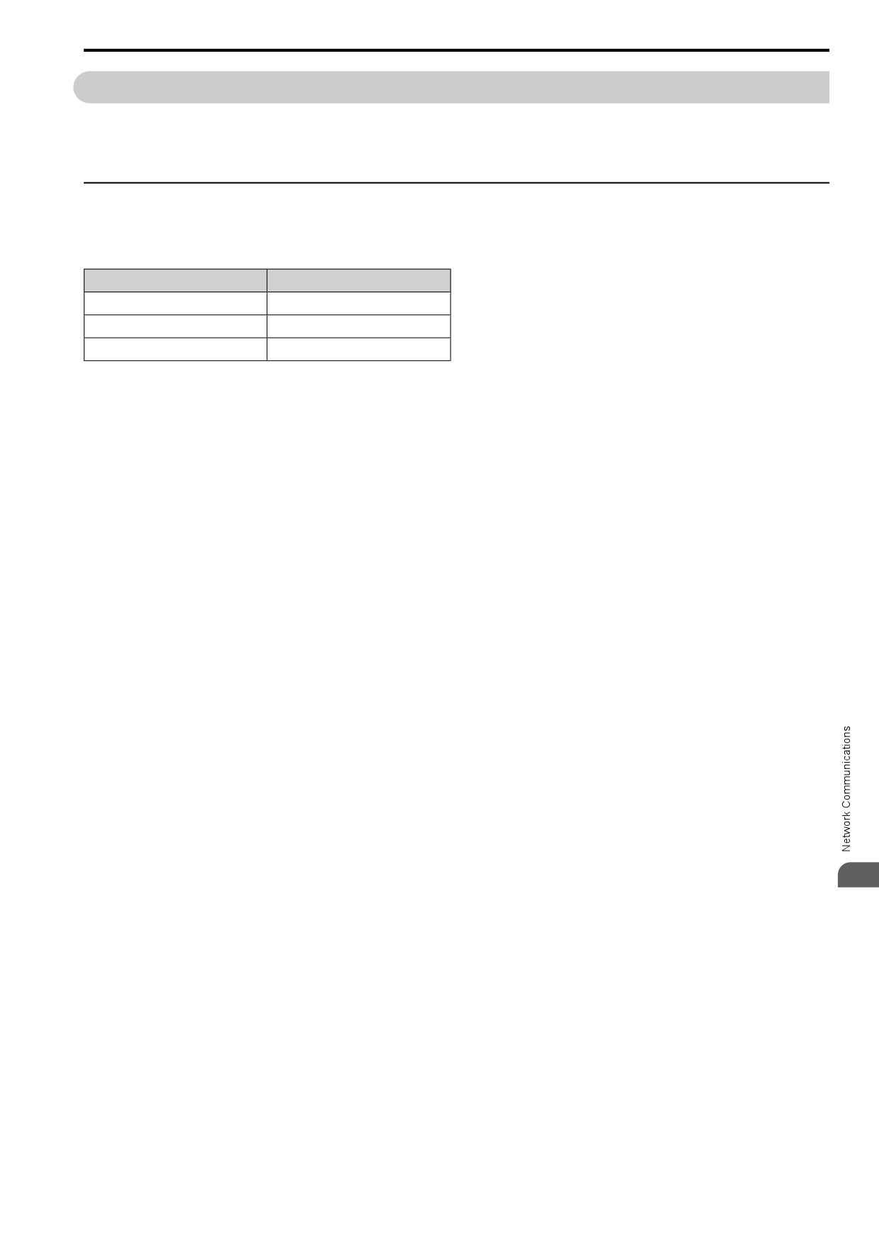
Table 6.1 Available Field Bus Network
Type of Communications
Option model
EtherCAT
SI-ES3
PROFINET
SI-EP3
EtherNet/IP
SI-EN3
6
189
6.3 Modbus Communications
6.3
Modbus Communications
This section gives detailed information about the parameters, error codes and communication procedures for
Modbus communications.
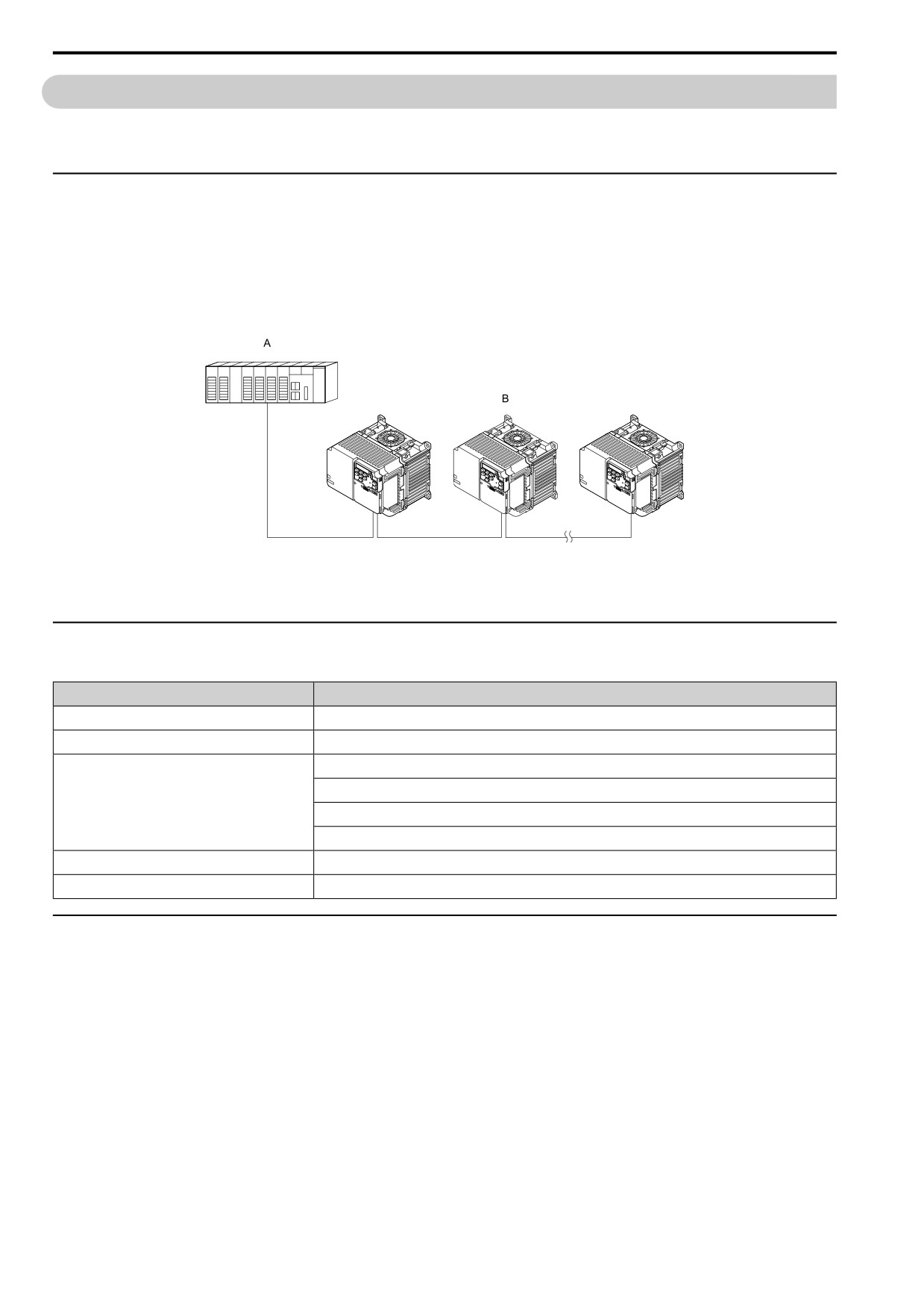
◆ Configure Master/Slave
You can use the Modbus protocol for serial communication with programmable controllers (PLC).
The Modbus communication uses one master (PLC) and a maximum of 31 slave drives. Serial communications
usually starts with a signal from the master to the slave drives.
A slave drive that receives a command from the master does the specified function and then sends a response back
to the master. You must set the address number for each slave drive before you start signal communications to
make sure that the master uses the correct address numbers.
A - Master (PLC)
B - Slave (drive)
Figure 6.1 PLC and Drive Connection Example
◆ Communication Specifications
Table 6.2 Modbus Specifications
Item
Specification
Interface
RS-485
Synchronization method
Asynchronous (start-stop synchronization)
Communications speed:1.2, 2.4, 4.8, 9.6, 19.2, 38.4, 57.6, 76.8, 115.2 kbps
Data length: 8 bit (fixed)
Communication parameter
Parity: even, odd, none
Stop bit 1 bit (fixed)
Communication protocol
Modbus standard (RTU mode only)
Number of possible units to connect
Maximum: 31 units
◆ Communication with the PLC
This section gives information about the settings for the termination resistor and how to connect to Modbus
communications. Modbus communications uses an RS-485 interface (2-wire sequence).
■ Connect Communications Cable
Use this procedure to start communication between the PLC and drive.
190
6.3 Modbus Communications
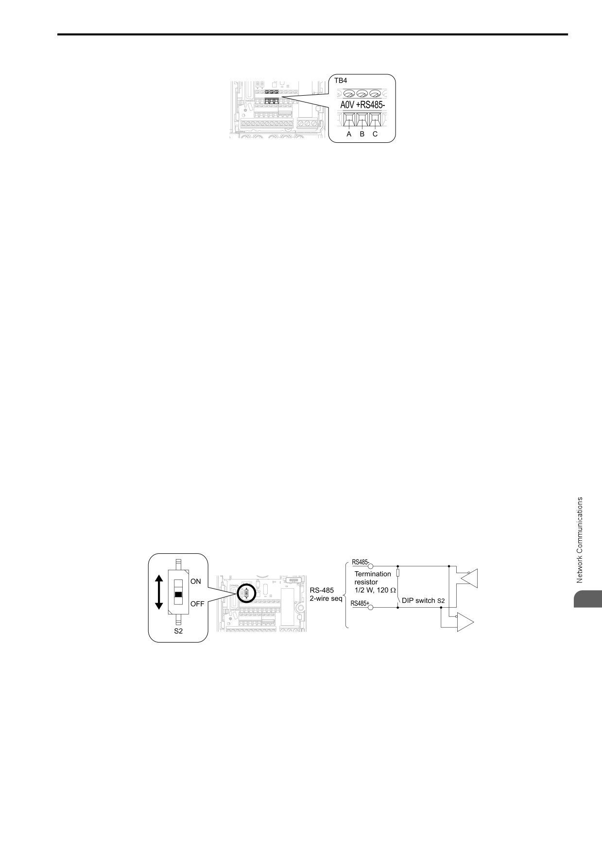
1. De-energize the drive then connect the communications cable to the PLC and the drive. The drive uses
terminal TB4 for Modbus communications.
A - Terminal
A0V: Shield ground
C
- Terminal RS485-: Communication input/output
(-)
B - Terminal
RS485+:
Communication input/output
(+)
Figure 6.2 Communications Cable Connection Terminal (TB4)
Note:
Isolate the communications wiring from the main circuit wiring and other high-power wiring Use shielded wires for the
communications wiring and connect cable sheaths to the ground terminal of the drive. Incorrect wiring procedures could
cause drive malfunction because of electrical interference.
2. Install the termination resistor on the network termination slave drive. Set DIP switch S2 to the ON position
to enable the termination resistor on the drive.
3. Energize the drive.
4. Use the drive keypad to set the necessary communications parameters H5-01 to H5-12.
• H5-01 [Mbus Address]
• H5-02 [Mbus BaudRate]
• H5-03 [Mbus Parity]
• H5-04 [Mbus Error Stop]
• H5-05 [Mbus Fault Detection Selection]
• H5-06 [Mbus Tx Wait Time]
• H5-09 [Mbus CE Detect Time]
• H5-10 [Mbus 0025H Unit Sel]
• H5-11 [Mbus ENTER Command Mode]
• H5-12 [Mbus Run Command Method Sel]
5. De-energize the drive and wait for the keypad display to turn off.
6. Energize the drive.
The drive is prepared to start communication with the PLC.
■ Set the Termination Resistor
You must enable
the termination resistor on the slave
terminal of the drive to use Modbus communications.
Use DIP switch
S2 on the terminal block to enable
and
disable the built-in termination resistor.
6
Figure 6.3 Modbus
Communication Terminal and DIP Switch S2
Use the tip of a
tweezers
or a jig
with a tip width of 0.8
mm (0.03 in) to set the DIP switch. When you install the
drive at the end of the communication line, set DIP switch S2 to ON. Set DIP switch S2 to OFF on all other
drives.
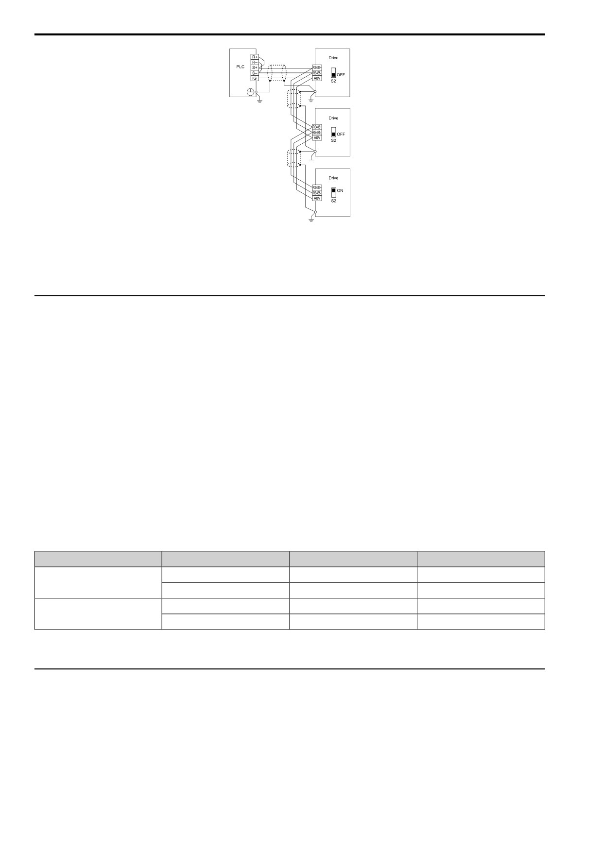
■ Wiring Diagram for More than One Drive
This is the correct wiring when you use more than one drive with Modbus communications.
191
6.3 Modbus Communications
Figure 6.4 Wiring Diagram for More than One Drive
Note:
1. Set DIP switch S2 to the ON position on the last drive of the Modbus communication network to enable the termination resistor.
2. When you remove the shield from the ground terminal, it can make the communication quality better.
◆ Modbus Drive Operations
Drive parameters will apply to the settings when the drive is running during Modbus communications. This
section gives information about the available functions and their related parameters.
■ Executable Functions
A PLC can do these operations with Modbus communications. Parameter settings (except H5-xx) do not have an
effect on the availability of these operations.
• Monitor the drive status and operate the drive
• Set and view parameters
• Fault Reset Procedure
• Multi-function input settings
The input command from Modbus communications and MFDI terminals (DI1 to DI7) are linked by a logical
OR operation.
■ Drive Control
Select the external command that sets the frequency references and motor run/stop with Modbus communications.
Use the following information to set the parameters as specified by the application.
Table 6.3 Necessary Parameter Settings for Drive Control from Modbus
LOCAL Control Selected
No.
Name
Setting Value
b1-01
Freq. Ref. Sel. 1
2 [Modbus]
External reference 1
b1-02
Run Comm. Sel 1
2 [Modbus]
b1-15
Freq. Ref. Sel. 2
2 [Modbus]
External reference 2
b1-16
Run Comm. Sel 2
2 [Modbus]
For more information about operation mode selection, refer to b1-01 [Freq. Ref. Sel. 1] and b1-02 [Run Comm.
Sel 1]. Refer to H1-xx = 9 [MFDI Function Select = Ext Ref 1/2] for more information about external command.
◆ Communications Timing
This section gives information about message timing.
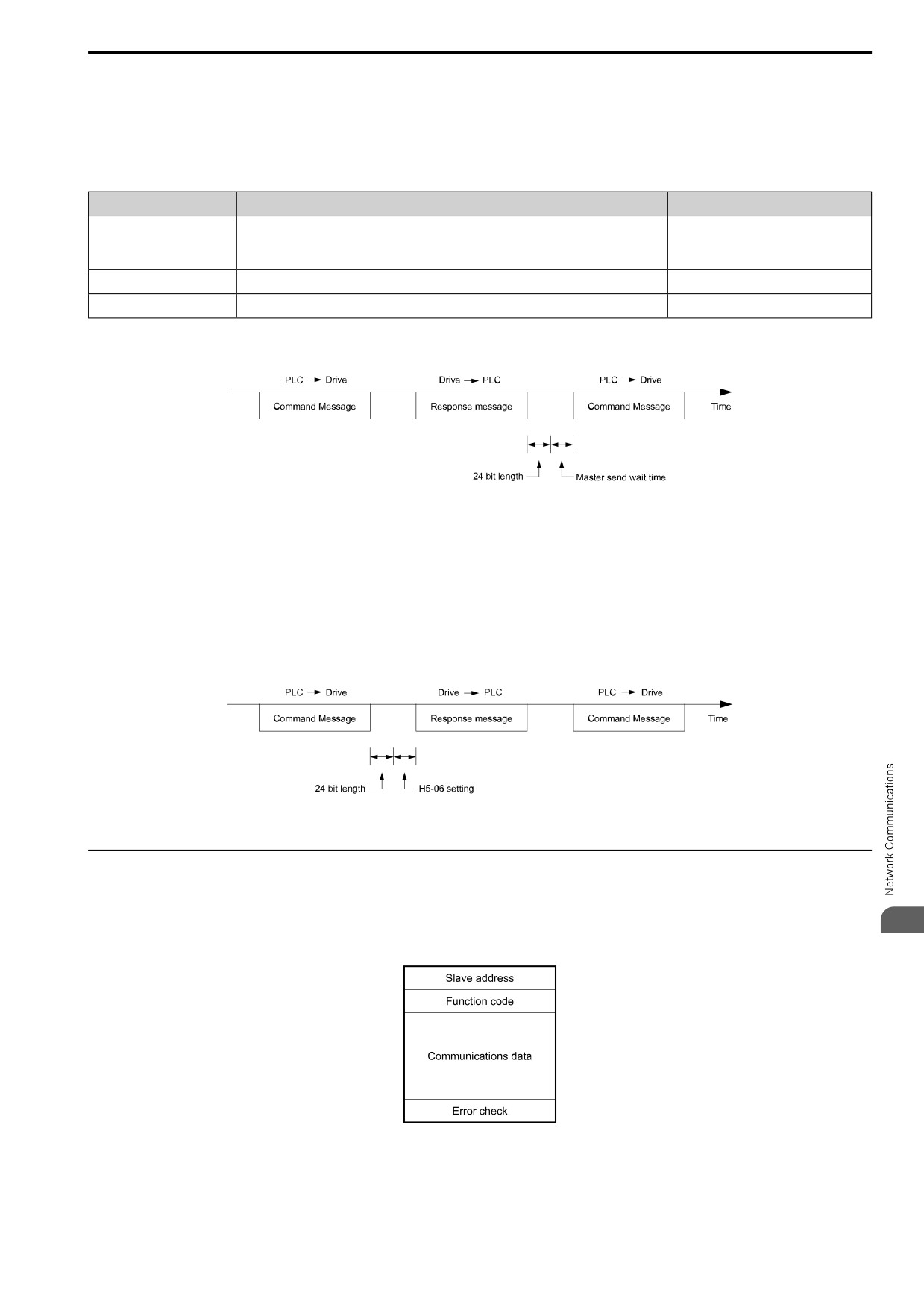
To prevent overrun of the slave side, the master cannot send a message to the same drive for a selected length of
time.
To prevent overrun of the master side, the slave cannot send a response message to the master for a selected length
of time.
192
6.3 Modbus Communications
■ Command Message from Master to Slave
To prevent data loss and overrun, after the master receives a message from the slave, the master cannot send the
same type of command message to the same slave for a selected length of time. The minimum wait time is
different for each type of message.
Table 6.4 Minimum Wait Time to Send a Message
Command Type
Example
Minimum Wait Time
• Operation commands (Run command, stop command)
1
• I/O settings
5 ms *1
• Reading the motor and parameter setting values
2
Writing a parameter
50 ms *1
3
Writing of modified data with the Enter command
3 to 5 s *1
*1
When the drive receives a message in the minimum wait time, it does command type 1 and sends a response message. If the drive
receives command type 2 or command type 3 messages in the minimum wait time, it will trigger a communications error or the drive
will ignore the command.
Figure 6.5 Minimum Wait Time to Send a Message
You must set the timer in the master to measure the length of time for the slave to respond to the master. If you set
the timer, but the slave does not send a response message in a specified length of time, the master will send the
message again.
■ Response Message from Slave
The slave receives the command message from the master then processes the data it received. The slave then waits
for the time set in H5-06 [Mbus Tx Wait Time] then sends a response message to the master. If overrun occurs on
the master, increase the wait time set in H5-06.
Figure 6.6 Response Wait Time
◆ Message Format
■ Communication Message Description
6
In Modbus communications, the master sends commands to the slave, then the slave responds. The master and
slave send their messages in the following configuration.
Figure 6.7 Message Format
The length of the data changes when the description of the command (function) changes.
193
6.3 Modbus Communications
■ Slave Address
Set the slave address of the drive to 00 to FF (Hex.). When the slave address is 00 (Hex), the master sends the
command and all slaves receive the command.
The slave will not send a response message to the master.
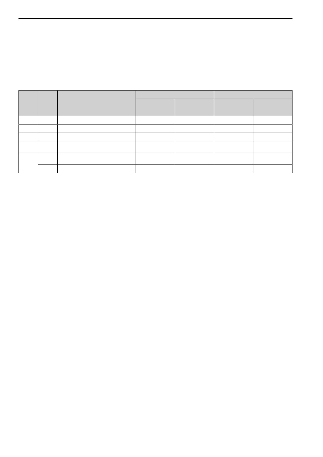
■ Function Code
There are five function codes that set commands.
Table 6.5 Function Codes
Command Message
Response Message
Subfunc
Function
tion
Code
Function
Minimum Data
Maximum Data
Minimum Data
Maximum Data
Code
(Hex.)
Length
Length
Length
Length
(Hex.)
(byte)
(byte)
(byte)
(byte)
03
-
Read the Description of Holding Register
8
8
7
37
08
-
Loopback Test
8
8
8
8
10
-
Writing to Multiple Holding Registers
11
41
8
8
Writing to Multiple Holding Registers / Reading
5A
-
11
41
17
17
the Register Indicated
Reading Contents of Non-Consecutive Holding
010D
10
248
10
248
Registers
67
010E
Writing to Non-Consecutive Holding Registers
14
250
8
8
■ Communications Data
Communications data is a series of data that uses the combination of the communications register number and the
data for these registers. The data length changes when the description of the command changes. For a loopback
test, it switches to test code.
The communications register for the drive has a 2-byte length. Data that is written to the register for the drive is
usually 2 bytes. Register data that is read from the drive is also 2 bytes.
■ Error Check
Error check uses the CRC-16 method to detect transmission errors. Use the procedure in this section to calculate
CRC-16.
Command Data
When the drive receives data, it will make sure that there are no errors in the data. The drive uses the procedure
below to calculate CRC-16, then compares that data with the CRC-16 value in the message. If the CRC-16 values
do not agree, the drive will not execute a command message.
When you calculate CRC-16 in Modbus communications, make sure that you set the start value as FFFF (Hex.).
All 16 bits must be 1.
Use this procedure to calculate CRC-16:
1. Make sure that the start value is FFFF (Hex.).
2. Calculate the FFFF (Hex.) start value and the XOR of the slave address (exclusive OR).
3. Move the step 2 results one column to the right. Do this shift until the carry bit is 1.
4. When the carry bit is 1, calculate XOR via the result from the above step 3 and A001 (Hex.).
5. Do steps 3 and 4 until the 8th shift to the right.
6. Use the result of step 5 to calculate the XOR and the data of the following messages (function code, register
address, data). Do steps 3 to 5 until the last data, then calculate.
7. The result of the last right shift or the value of the last XOR calculation is the result for CRC-16.
Figure 6.8 lists examples of the CRC-16 calculation of slave address 02 (Hex.) and function code 03 (Hex.). The
calculated results of CRC-16 for this section is D140 (Hex.).
Note:
The calculation example only gives information about some error checks with CRC-16. The drive will do the same error checks for the
next data.
194
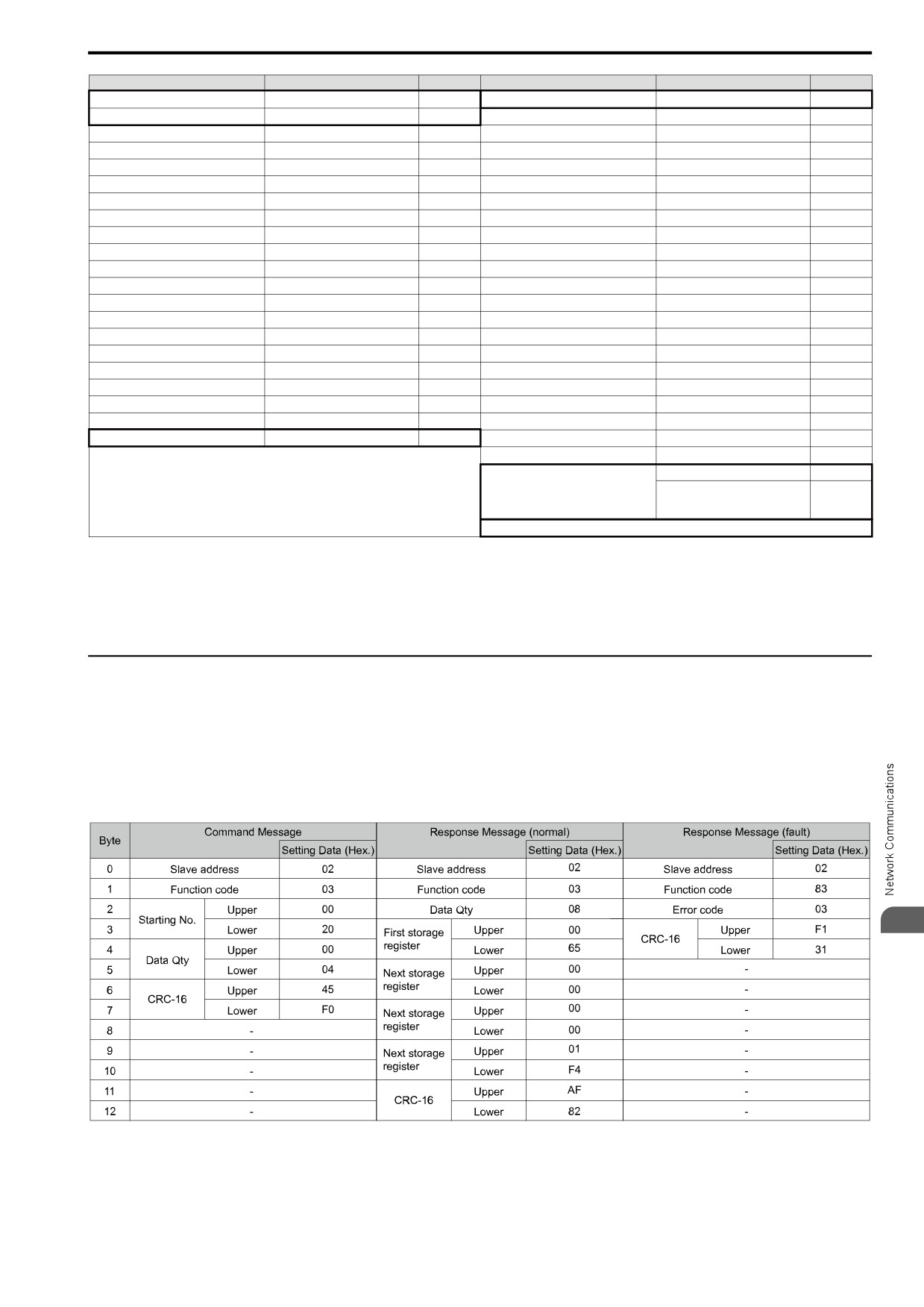
6.3 Modbus Communications
Description
Calculation
Overflow
Description
Calculation
Overflow
Initial value (FFFF(Hex.))
1111 1111 1111 1111
Function code 03 (Hex.)
0000 0011
Address 02 (Hex.)
0000 0010
XOR w result
1000 0001 0011 1101
XOR w initial value
1111 1111 1111 1101
Shift 1
0100 0000 1001 1110
1
Shift 1
0111 1111 1111 1110
1
XOR w A001 (Hex.)
1010 0000 0000 0001
XOR w A001 (Hex.)
1010 0000 0000 0001
XOR result
1110 0000 1001 1111
XOR result
1101 1111 1111 1111
Shift 2
0111 0000 0100 1111
1
Shift 2
0110 1111 1111 1111
1
XOR w A001 (Hex.)
1010 0000 0000 0001
XOR w A001 (Hex.)
1010 0000 0000 0001
XOR result
1101 0000 0100 1110
XOR result
1100 1111 1111 1110
Shift 3
0110 1000 0010 0111
0
Shift 3
0110 0111 1111 1111
0
Shift 4
0011 0100 0001 0011
1
Shift 4
0011 0011 1111 1111
1
XOR w A001 (Hex.)
1010 0000 0000 0001
XOR w A001 (Hex.)
1010 0000 0000 0001
XOR result
1001 0100 0001 0010
XOR result
1001 0011 1111 1110
Shift 5
0100 1010 0000 1001
0
Shift 5
0100 1001 1111 1111
0
Shift 6
0010 0101 0000 0100
1
Shift 6
0010 0100 1111 1111
1
XOR w A001 (Hex.)
1010 0000 0000 0001
XOR w A001 (Hex.)
1010 0000 0000 0001
XOR result
1000 0101 0000 0101
XOR result
1000 0100 1111 1110
Shift 7
0100 0010 1000 0010
1
Shift 7
0100 0010 0111 1111
0
XOR w A001 (Hex.)
1010 0000 0000 0001
Shift 8
0010 0001 0011 1111
1
XOR result
1110 0010 1000 0011
XOR w A001 (Hex.)
1010 0000 0000 0001
Shift 8
0111 0001 0100 0001
1
XOR result
1000 0001 0011 1110
XOR w A001 (Hex.)
1010 0000 0000 0001
XOR result
1101 0001 0100 0000
1101 0001 0100 0000
D
1
4
0
CRC-16
Perform operations with next data (function code)
(Lower)
(Upper)
Continue from here with next data.
Figure 6.8
CRC-16 Calculation Example
Response Data
The drive does the CRC-16 calculation for the response message and makes sure that the data does not have
errors. Make sure that the calculated value is the same value as the CRC-16 in the response message.
◆ Examples of Messages for Commands/Responses
The items in this section are examples of messages for commands/responses.
■ Read the Description of Holding Register
Uses function code 03 (Hex.) to read the contents of a maximum of 16 holding registers.
These are example messages when the drive reads status signal from the drive of slave 2, the error contents, fault
contents, and frequency references.
6
Figure 6.9 Message Example When Reading the Contents of Holding Register
195
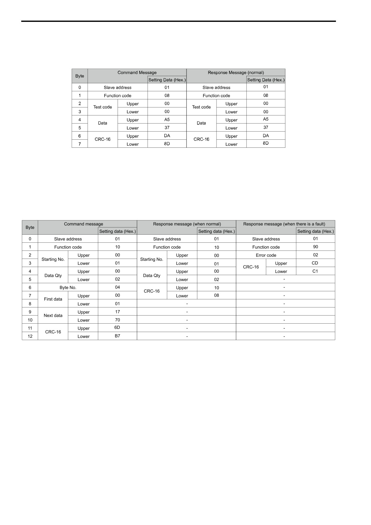
6.3 Modbus Communications
■ Loopback Test
The loopback test uses function code 08 (Hex.) and returns the command message as a response message. This
test checks communication between the master and slave. The test code and data can use desired values.
These are examples of messages given out when the loopback test is done with the drive of slave 1.
Figure 6.10 Message Example When Doing the Loopback Test
■ Writing to Multiple Holding Registers
You can write the data that you set to the number of holding registers set in function code 10 (hex). You must
configure the number of the holding registers and each 8 higher bits and 8 lower bits in order in the command
message for the write data. You can write to a maximum of 16 holding registers.
These are example messages when you use the PLC to set Forward run in the drive of slave 1 with a 60.00 Hz
frequency reference.
Figure 6.11 Message Example When Writing to Multiple Holding Registers
Note:
The number of bytes set in the command message set the data quantity × 2 during the command message. The response message uses
the same formula.
When you rewrite the parameter value with the write command through the H5-11 [Mbus ENTER Command
Mode] setting, you must use the Enter command to save and enable the contents of the changes.
■ Reading from More than One Holding Register/Reading the Indicated Register
The drive uses function code 5A (Hex.) to write to more than one register, then it reads the contents of four
holding registers at the same time.
The function for writing to more than one register is the same as the function for function code 10 (Hex.). You can
write to a maximum of 16 holding registers.
The four holding registers to be read from are specified in H5-25 to H5-28 [Mbus 5A RegX Selection].
This table shows example messages when you write to more than one holding register or when you read more
than one command register, this register data is used for the examples:
• The drive for slave 1 is set for Forward run with a frequency reference of 60.00 Hz.
196
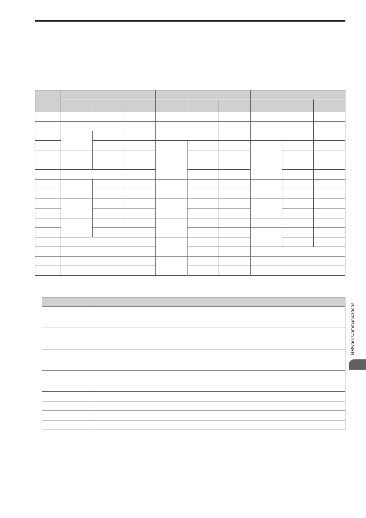
6.3 Modbus Communications
•
The setting in H5-25 to H5-28 and the data in the specified holding registers are as follows.
- H5-25 = 0044H: U1-05 [Motor Speed] = 60.00 Hz (6000 = 1770H)
- H5-26 = 0045H: U1-06 [Output Voltage Ref] = 200.0 V (2000 = 07D0H)
- H5-27 = 0042H: U1-03 [Output Current] = 50% of drive rated current (100% = 8192, 50% = 4096 = 1000H)
- H5-28 = 0049H: U1-10 [In Terminal Status] = 00H
Table 6.6 Message Example When Reading from More than One Holding Register/Reading the Indicated Register
Command Message
Response Message (When Normal)
Response Message (When There is a Fault)
Byte
Setting Data
Setting Data
Setting Data
(Hex.)
(Hex.)
(Hex.)
0
Slave address
01
Slave address
01
Slave address
01
5A
1
Function code
5A
Function code
Function code
DA
2
Upper
00
Register status
0F
Register status
0F
Starting No.
Data in holding
Data in holding
3
Lower
01
Upper
17
Upper
17
register 1
register 1
selected with
selected with
4
Upper
00
H5-25
Lower
70
H5-25
Lower
70
Data Quantity
5
Lower
02
Data in holding
Upper
07
Data in holding
Upper
07
register 2
register 2
selected with
selected with
6
Byte No.
04
Lower
D0
Lower
D0
H5-26
H5-26
Data in holding
Data in holding
7
Upper
00
Upper
10
Upper
10
register 3
register 3
First data
selected with
selected with
8
Lower
01
H5-27
Lower
00
H5-27
Lower
00
9
Upper
17
Data in holding
Upper
00
Data in holding
Upper
00
register 4
register 4
Next data
selected with
selected with
10
Lower
70
Lower
00
Lower
00
H5-28
H5-28
11
Upper
4F
Upper
00
Error code
02
CRC-16
Starting No.
12
Lower
43
Lower
01
Upper
E9
CRC-16
13
-
Upper
00
Lower
6C
Data Quantity
14
-
Lower
02
-
15
-
Upper
AC
-
CRC-16
16
-
Lower
D0
-
Note:
The number of bytes set in the command message set the data quantity × 2 during the command message.
Register status
bit 0
Data in register 1 selected with H5-25
1: Successfully read the register
0: Register read error
bit 1
Data in register 2 selected with H5-26
1: Successfully read the register
0: Register read error
bit 2
Data in register 3 selected with H5-27
1: Successfully read the register
0: Register read error
6
bit 3
Data in register 4 selected with H5-28
1: Successfully read the register
0: Register read error
bit 4
Not used
bit 5
Not used
bit 6
Not used
bit 7
Not used
When you rewrite the parameter value with the write command through the H5-11 [Mbus ENTER Command
Mode] setting, you must use the Enter command to save and enable the contents of the changes.
■ Reading the Contents of Non-Consecutive Holding Registers
The drive uses function code 67 (Hex.) and subfunction code 010D (Hex.) to read data with a maximum of 120
holding registers.
197
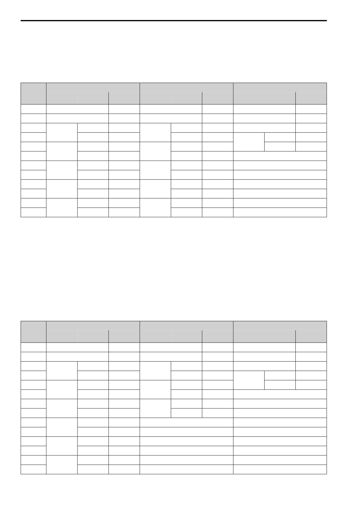
6.3 Modbus Communications
You must give the holding register number from which to read separately.
This table shows example messages when you read the frequency reference and torque limit from the drive for
slave 1, this register data is used for the examples:
•
0024H: U1-01 [Frequency Reference] = 60.00 Hz (6000 = 1770H)
•
0028H: U1-09 [Torque Reference] = 100.0% (1000 = 03E8H)
Table 6.7 Message Example When Reading the Contents of Non-Consecutive Holding Registers
Command Message
Response Message (When Normal)
Response Message (When There is a Fault)
Byte
Setting Data
Setting Data
Setting Data
(Hex.)
(Hex.)
(Hex.)
0
Slave address
01
Slave address
01
Slave address
01
1
Function code
67
Function code
67
Function code
E7
2
Upper
01
Upper
01
Error code
02
Subfunction
Subfunction
code
code
3
Lower
0D
Lower
0D
Upper
EA
CRC-16
4
Upper
00
Upper
00
Lower
31
Data Quantity
Byte No.
5
Lower
02
Lower
04
-
6
Upper
00
Upper
17
-
Holding register
Holding register
1 No.
1 data
7
Lower
24
Lower
70
-
8
Upper
00
Upper
03
-
Holding register
Holding register
2 No.
2 data
9
Lower
28
Lower
E8
-
10
Upper
8B
Upper
47
-
CRC-16
CRC-16
11
Lower
29
Lower
ED
-
Note:
The number of bytes set in the command message set the data quantity × 2 during the command message.
■ Writing to Non-Consecutive Holding Registers
The drive uses function code 67 (Hex.) and subfunction code 010E (Hex.) to read data with a maximum of 60
holding registers.
You must give the holding register number from which to write separately.
This table shows example messages when you write the frequency reference and torque limit from the drive for
slave 1, this register data os used for the examples:
•
0002H: Frequency Reference = 60.00 Hz (6000 = 1770H)
•
0004H: Torque Limit = 150.0% (1500 = 05DCH)
Table 6.8 Message Example When Writing to Non-Consecutive Holding Registers
Command Message
Response Message (When Normal)
Response Message (When There is a Fault)
Byte
Setting Data
Setting Data
Setting Data
(Hex.)
(Hex.)
(Hex.)
0
Slave address
01
Slave address
01
Slave address
01
1
Function code
67
Function code
67
Function code
E7
2
Upper
01
Upper
01
Error code
02
Subfunction
Subfunction
code
code
3
Lower
0E
Lower
0E
Upper
EA
CRC-16
4
Upper
00
Upper
00
Lower
31
Data Quantity
Data Quantity
5
Lower
02
Lower
02
-
6
Upper
00
Upper
D5
-
Byte No.
CRC-16
7
Lower
04
Lower
FC
-
8
Upper
00
-
-
Holding register
1 No.
9
Lower
02
-
-
10
Upper
17
-
-
Holding register
1 data
11
Lower
70
-
-
12
Upper
00
-
-
Holding register
2 No.
13
Lower
04
-
-
198