Q2V Driving Quality. Technical Manual (Item code: Q2V-Axxxx-xxx, 2020) - page 3
3.6 Control I/O Connections
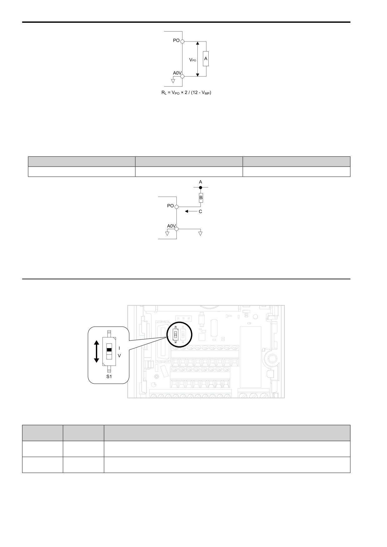
A - Load Impedance
Figure 3.28 Wiring to Use Pulse Train Output in Sourcing Mode
• Use in sinking mode
The external power supply changes the voltage level of the pulse train output signal. Keep the voltage from an
external source between 10.8 Vdc to 16.5 Vdc. Adjust the load impedance to keep the current at 16 mA or
lower.
External Power Supply (V)
Load Impedance (kΩ)
Sinking current (mA)
10.8 Vdc to 16.5 Vdc
1.0 kΩ or more
16 mA maximum
A - External power supply
C - Sinking current
B - Load Impedance
Figure 3.29
Wiring to Use Pulse Train Output in Sinking Mode
◆ Set the Input Signal for the
MFAI Terminal AI2
Use terminal AI2 to input a voltage or a
current signal.
Figure 3.30 Location of DIP Switch S1
Table 3.17 MFAI Terminal AI2 Signal Settings
DIP Switch S1
Parameter
Input Signal
Settings
Signal Level
I
H3-09 = 2: 4 mA to 20 mA/0% to 100% (input impedance: 250 Ω)
Current input
(Default)
H3-09 = 3: 0 mA to 20 mA/0% to 100% (input impedance: 250 Ω)
H3-09 = 0: 0 V to 10 V/0% to
100% (with zero limit)
(input impedance:
20 kΩ)
Voltage input
V
H3-09 = 1: 0 V to 10 V/0% to 100% (without zero limit) (input
impedance: 20 kΩ)
Note:
Use tweezers or a jig with a tip width of approximately 0.8 mm (0.03 in) to set DIP switches.
82
3.6 Control I/O Connections
◆ Set the Output Signal for the MFAO Terminal AO
Set the signal type for terminal AO
to voltage or
current output. Use jumper S5 and H4-07 [AO Signal Level
Select] to set the signal type.
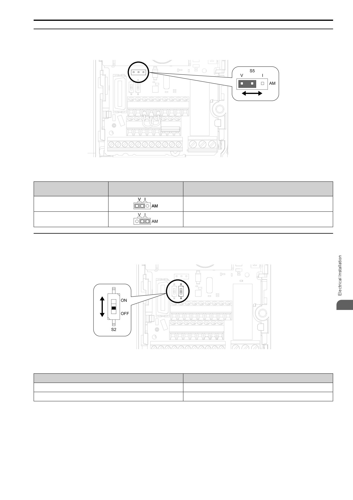
Figure 3.31 Location of Jumper Switch S5
Table 3.18 MFAO Terminal AO Signal
Settings
Parameter
Types of Output Signals
Jumper S5
Signal Level
Voltage output
H4-07
= 0: 0 V to 10 V
(Default)
Current output
H4-07 = 2: 4 mA to 20 mA
◆ Switch ON Termination Resistor for Modbus Communications
When the drive is the last slave in a Modbus communications, set DIP switch S2 to the
ON position. This drive
has a built-in termination resistor for the
RS-485 interface.
3
Figure 3.32 Location of DIP Switch S2
Table 3.19 Modbus Communications Termination Resistor Setting
DIP Switch S2
Description
ON
The
built-in termination resistor
is ON.
OFF (Default)
The
built-in termination resistor
is OFF.
83
3.7 Connect the Drive to a PC
3.7
Connect the Drive to a PC
The drive has a mini-B type USB port.
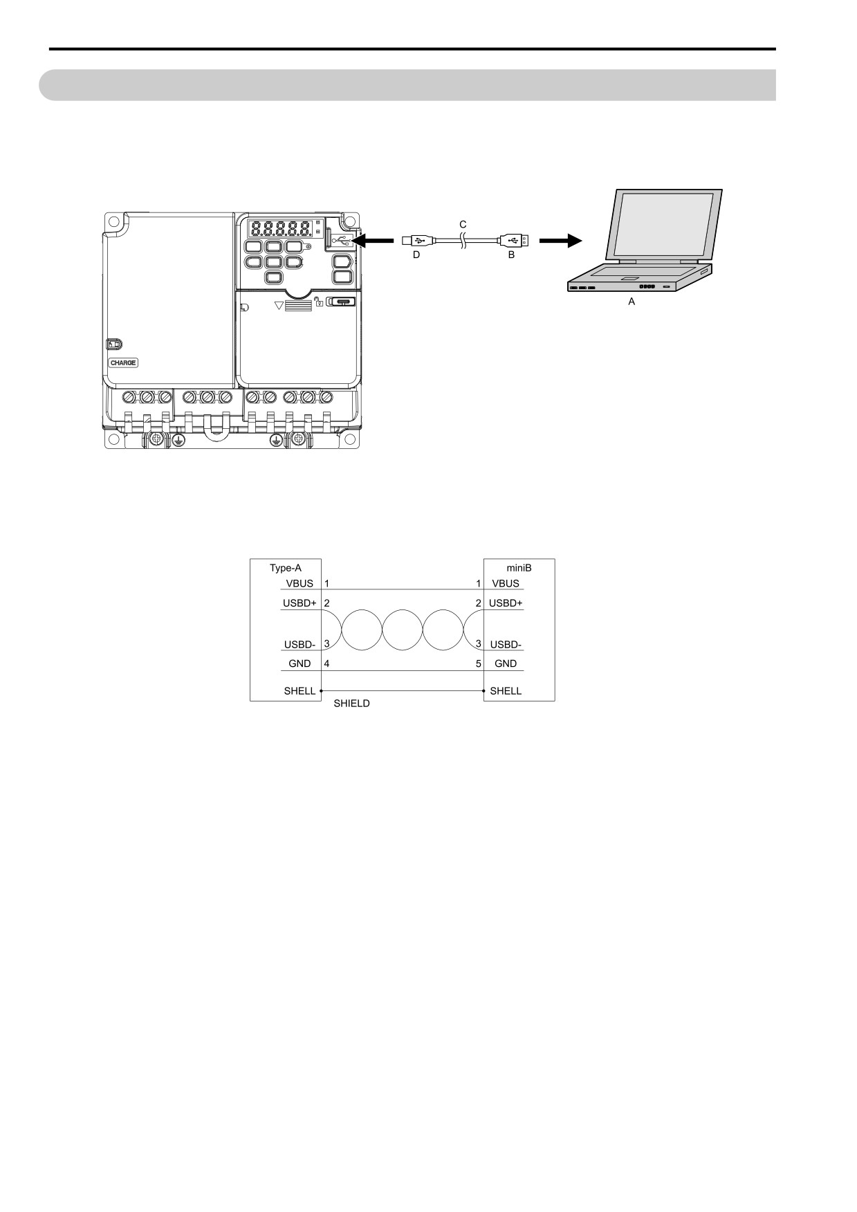
You can use a USB cable (USB 2.0, type: A - mini-B) to connect the drive to a type-A USB port on a PC. After
you connect the drive to the PC, you can use Q2Edit software to monitor drive performance and manage
parameter settings.
A - PC
C - USB 2.0, type A - mini-B cable
B - Type-A connector
D - Mini-B type connector
Figure 3.33 Connect to a PC (USB)
A USB cable with connectors connected with shielded wires is recommended.
Figure 3.34 Recommended USB Cable
84
3.8 External Interlock
3.8
External Interlock
For applications that will have unwanted effects on the system if the drive stops, make an interlock between
MFDO terminals set to H2-xx = 3 [MFDO Function Select = Fault] and H2-xx = 1 [Drive Ready].
◆ Drive Ready
When the drive is operating or is prepared to accept a Run command, the MFDO terminal to which Drive Ready
[H2-xx = 1] is set will enter the ON status.
In these conditions, Drive Ready is OFF and the drive ignores Run commands:
• The drive is de-energized
• During a fault
• There is problem with the control power supply
• There is a parameter setting error that will not let the drive run, although a Run command is entered
• An overvoltage or undervoltage fault occurs when the Run command is entered
• The drive is in Programming Mode.
◆ Interlock Circuit Example
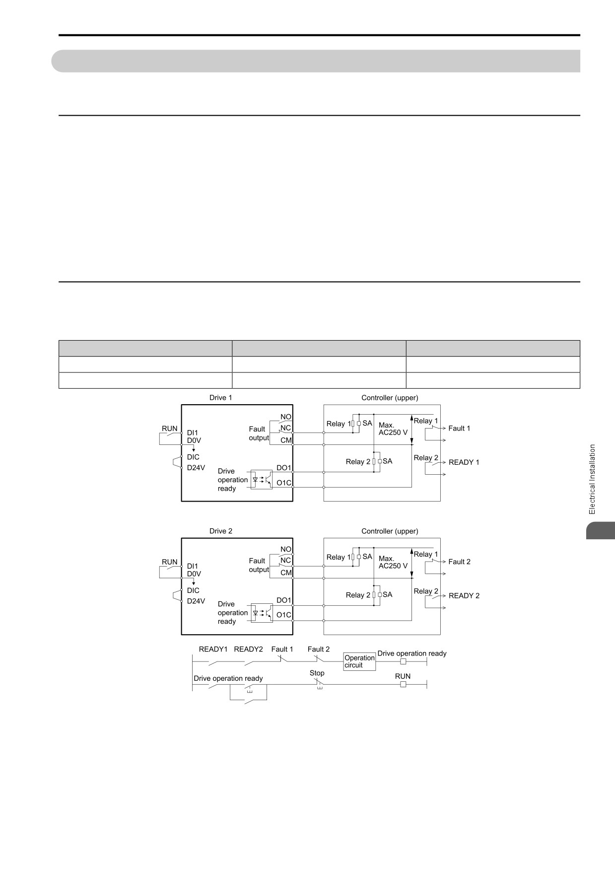
This is an example of how two drives that run one application use the Drive Ready and Fault output signals to
interlock with the controller.
Terminal
Output Signal
Parameter Settings for Output Signal
NO, NC, CM
Fault
H2-01 = 3
DO1-O1C
Drive Ready
H2-02 = 1
3
Figure 3.35 Interlock Circuit Example
85
3.9 Braking Resistor Installation
3.9
Braking Resistor Installation
A braking resistor or braking resistor unit (dynamic braking option) helps stop the motor quickly and smoothly
when there is high load inertia.
If you try to decelerate a motor in less time than usual for a coast to stop, the motor will rotate faster than the
synchronous speed that aligns with the set frequency. This will cause the motor to become an induction generator.
The inertia energy of the motor and regenerate to the drive and charge the drive DC bus capacitor and increase the
voltage. If the voltage is more than the overvoltage level, an ov [Overvoltage] will occur. To prevent these
overvoltage faults, a dynamic braking option is necessary.
WARNING!
Set L3-04 = 0 [StallP@Decel Enable = Disabled] when you operate the drive with:
• a regenerative converter
• regenerative unit
• braking resistor
• braking resistor unit.
If you set the parameter incorrectly, the drive can decelerate for too long and cause serious injury or death.
NOTICE: Before you connect a dynamic braking option to the drive, make sure that qualified personnel read and obey the
Braking Unit and Braking Resistor Unit Installation Manual (TOBPC72060001). If you do not read and obey the manual or if
personnel are not qualified it can cause damage to the drive and braking circuit.
Note:
• Select the correct braking circuit size to dissipate the power that is necessary to decelerate the load in the correct time. Before you run
the drive, make sure that the braking circuit can dissipate the energy for the set deceleration time.
• To install a dynamic braking option, set L8-01 = 0 [3%ERF DBR Protection = Disabled].
WARNING! Fire Hazard. Do not connect a braking resistor to terminals +1 or -. Use terminals B1 and B2 for the braking resistor
connections. If you connect a braking resistor to the incorrect terminals, it can cause damage to the drive and braking circuit and
serious injury or death.
NOTICE: Connect braking resistors to the drive as shown in the connection diagram examples. If you wire the braking circuits
incorrectly, it can cause damage to the drive or equipment.
To connect a Yaskawa ERF series braking resistor to the drive, set L8-01 = 1 [Enabled].
To use a non-ERF-type braking resistor, connect a thermal overload relay between the drive and the braking
resistor and set a circuit to turn OFF the drive power at the trip contacts of the thermal overload relay.
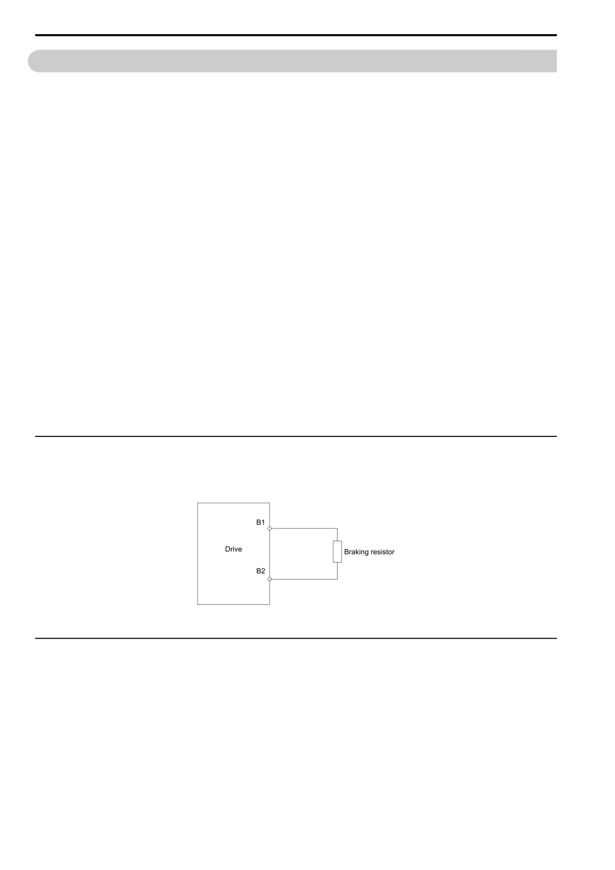
◆ Install a Braking Resistor: ERF-Type
Connect a braking resistor to drive models 2001 to 2021, B001 to B018, and 4001 to 4012. When you use a
braking resistor, set L8-01 = 1 [3%ERF DBR Protection = Enabled] and set one of the MFDO parameters H2-01
to H2-03 = 4C [MFDO Function Select = BrkRes Fault]. Use a sequence to turn OFF the power with a MFDO.
Figure 3.36 Install an ERF-Type Braking Resistor
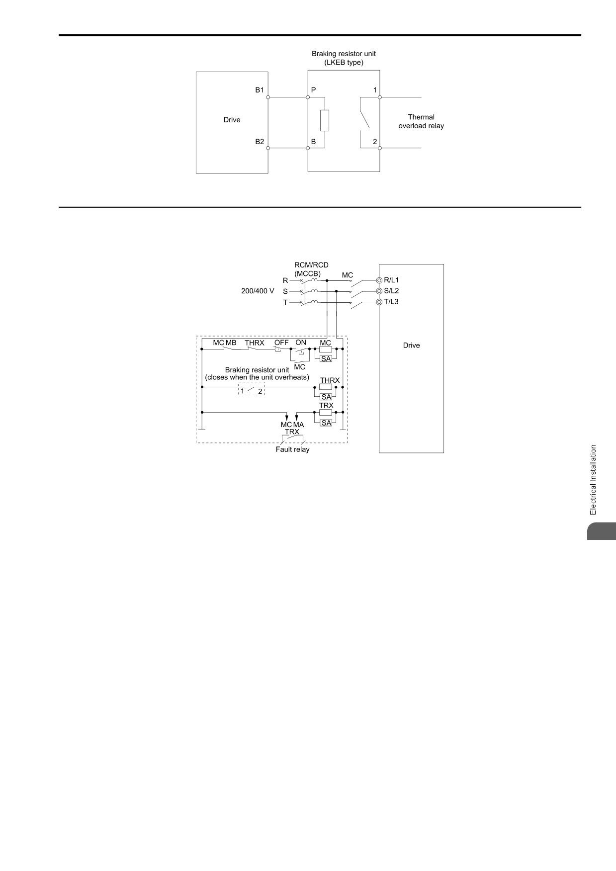
◆ Install a Braking Resistor Unit: LKEB-Type
Connect the braking resistor unit as shown. To install a braking resistor unit, set L8-01 = 0 [3%ERF DBR
Protection = Disabled].
This product has a built-in braking transistor.
To prevent overheating the braking resistor unit, set a sequence to de-energize the drive at the trip contacts of the
thermal overload relay.
86
3.9 Braking Resistor Installation
Figure 3.37 Install a Braking Resistor Unit: LKEB-Type
◆ Dynamic Braking Option Overload Protection
To prevent overheating the dynamic braking option, set a sequence to de-energize the drive at the trip contacts of
the thermal overload relay.
Figure 3.38 Power Supply Interrupt for Overheat Protection Example
WARNING! Fire Hazard. When you use a braking unit, use a thermal relay on the braking resistors and set a fault contact
output for the braking resistor unit to disconnect drive main power through an input contactor. Incorrect braking circuit protection
can cause the resistors to become too hot and cause serious injury or death.
3
87
3.10 Drive Wiring Protection
3.10
Drive Wiring Protection
◆ Installing a Earth Leakage Circuit Breaker (RCM/RCD)
When the drive output does switches at high speeds, it causes high frequency leakage current. To prevent
electrical shock and fires caused by ground fault protection that is not sufficient, install an RCM/RCD. Use a high
frequency RCM/RCD at the power input side of the drive and make sure that each drive has a minimum
cumulative sensitivity amperage of 30 mA. The specialized breaker detects only the leakage current from
frequency bands that are dangerous to humans.
If a device does not have protection against high frequencies, high frequency leakage currents can cause the
device to malfunction. If you have a malfunction on a device that is not protected, decrease the carrier frequency
of the drive, switch to a better breaker, or use an RCM/RCD with a minimum cumulative sensitivity amperage of
200 mA for each drive.
These conditions can have an effect on leakage current:
• Drive capacity
• Carrier frequency
• Wiring distance and types of motor cables
• EMI/RFI filter
To prevent damage and injury to personnel and drives, use a high-frequency RCM/RCD that is rated for AC and
DC power supplies.
Note:
The manufacturer recommends the following RCMs/RCDs, which are designed to operate with high frequencies.
• Mitsubishi Electric Corporation; NV series
• Schneider Electric; NS series
You can use a molded-case circuit breaker (MCCB) as a replacement for an RCM/RCD that is upstream in the
power supply system.
◆ Install a Molded-Case Circuit Breaker (MCCB) or Residual Current Monitor/
Device (RCM/RCD)
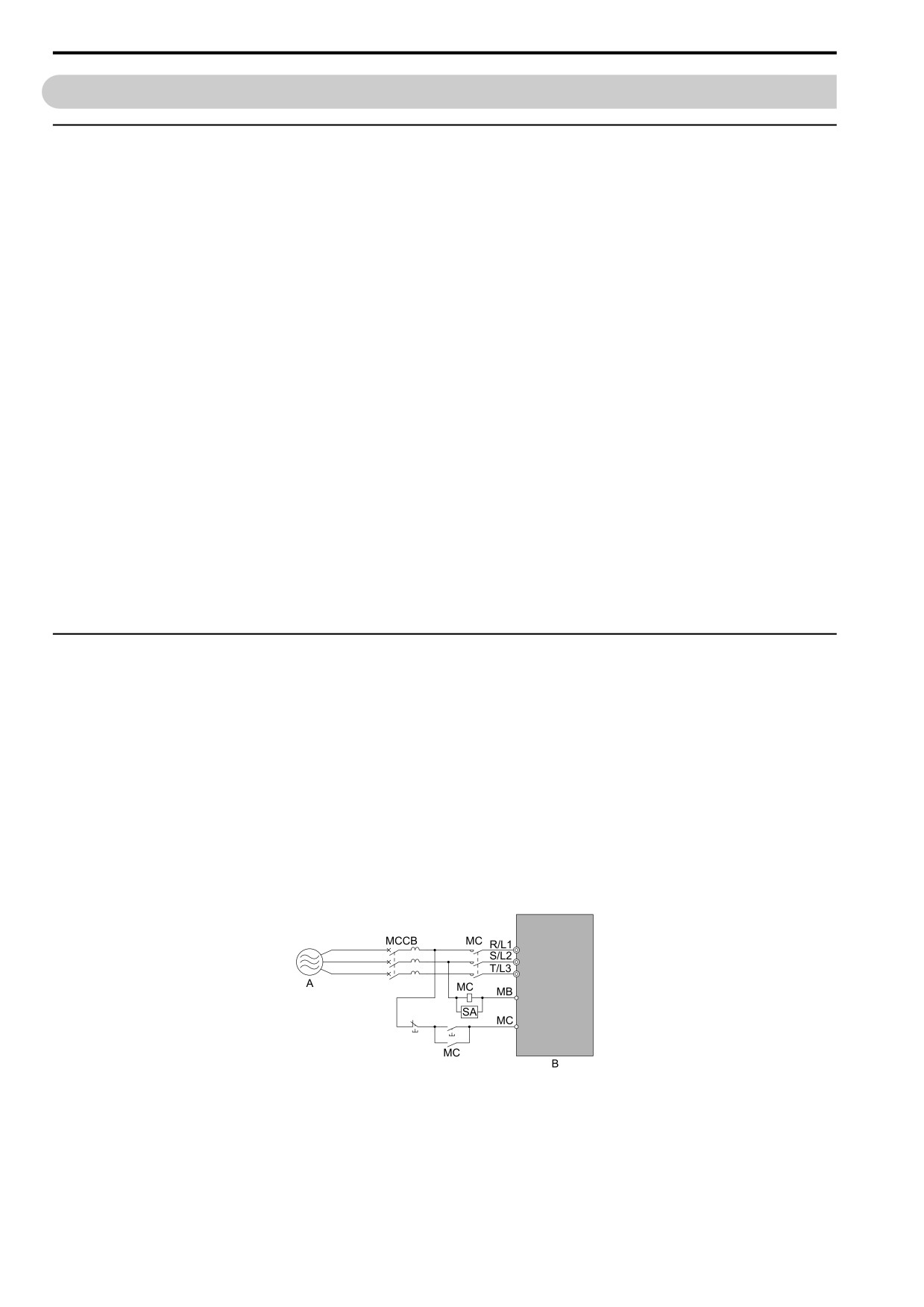
Install a molded-case circuit breaker (MCCB) or a ground fault circuit interrupter (RCM/RCD) for line protection
between the power supply and main circuit power supply input terminals R/L1, S/L2, and T/L3. The MCCB/
RCM/RCD give overload protection and also prevent damage to the main circuit and the devices that are wired to
the main circuit.
Use the information in this section to select the correct MCCB or RCM/RCD and to safely connect the device.
• The capacity of the MCCB or GFCI must be 1.5 to 2 times the rated output current of the drive. Use an MCCB
or RCM/RCD as an alternative to overheat protection (150% for one minute at the rated output current) to
prevent drive faults.
• When you connect more than one drive to one MCCB or RCM/RCD that is shared between multiple drives or
with other equipment, use a magnetic contactor (MC) and set a sequence that de-energizes the drive when it
outputs errors.
A - Power supply
B - Drive
Figure 3.39 Connect an MCCB
WARNING! Electrical Shock Hazard. Use an MCCB, RCM/RCD, or Magnetic Contactor (MC) to de-energize the drive before
you wire the main circuit terminal. If the main circuit terminal is energized during wiring, it will cause serious injury or death.
88

3.11 Dynamic Braking Option, Motor Protection
3.11
Dynamic Braking Option, Motor Protection
◆ Install an Electromagnetic Contactor (MC) at the Input Side of the Drive
You can use an MC as an alternative to a molded case circuit breaker (MCCB) when:
• The protective functions of the drive have been triggered
• An emergency stop occurred, and the sequence de-energizes the drive.
If an MC on the input side of the drive (primary side) stops the drive, regenerative braking will not operate, and
the drive will coast to stop.
NOTICE: When you connect electromagnetic switches or magnetic contactors to the output motor circuits, make sure that you
sequence them correctly. If the output motor circuit sequence is incorrect, it can cause damage to the drive.
NOTICE: The drive can fail if users frequently turn the drive ON and OFF with the MC on the power source side to Run and
Stop the drive. Incorrect operation can decrease the service life of the relay contacts and electrolytic capacitors. If you
frequently use the magnetic contactor on the power source side to Run and Stop the drive, it can cause drive failure.
Note:
• When machinery must not restart after recovery from a momentary power loss that occurred during run, install an MC at the input side
of the drive and set a sequence that does not automatically set the Run command to ON after recovery of power.
• When it is necessary to stop momentary power loss, for example to maintain a circuit that has momentary power loss, use a delayed-
release MC.
• Use an MC (magnetic contactor) to make sure that you can fully remove power to the drive when necessary. Wire the MC to open
when a fault output terminal is triggered.
■ Protect the Braking Resistor/Braking Resistor Unit
Use an MC on the input side (primary side) to prevent damage to the braking resistor/braking resistor unit.
WARNING! Fire Hazard. When you use a braking unit, use a thermal relay on the braking resistors and set a fault contact
output for the braking resistor unit to disconnect drive main power through an input contactor. Incorrect braking circuit protection
can cause the resistors to become too hot and cause serious injury or death.
◆ Install a Thermal Overload Relay on the Drive Output
A thermal overload relay disconnects the power line to the motor during a motor overload condition to prevent
damage to the motor. Install a thermal overload relay between the drive and motor in these conditions:
• When operating more than one motor from one drive.
• When operating the motor directly from the power line with a power line bypass.
When operating one motor from one drive, it is not necessary to install a thermal overload relay. The drive has
electronic motor overload protection in the drive software.
Note:
3
• When you install a thermal overload relay, set parameter L1-01 = 0 [Motor Cool Type for OL1 Calc = Disabled].
• Set up a sequence that will trip an external fault (coast to stop) for the contacts of the thermal overload relay.
■ General Precautions When Using Thermal Overload Relays
When you use a motor thermal overload relay on the drive output to prevent nuisance trips and overheating of the
motor at low speeds, be sure to think about these application precautions:
• Operation of a low speed motor
• When you operate more than one motor with one drive
• Length of the motor cables
• Nuisance tripping because of high drive carrier frequency
Operation of a Low Speed Motor
Usually, you use thermal overload relays on general-purpose motors (standard motors). When a drive drives a
general-purpose motor, the motor current is approximately 5% to 10% more than with a commercial power
supply. When a motor with a shaft-driven fan operates at low speeds, the cooling capacity decreases. This can
cause the motor to overheat when the load current is in the motor rated value. Enable the electronic thermal
protection in the drive when possible to prevent this problem.
The electronic thermal overload function uses the relation between the speed and heat characteristics in the
variable speed control range to simulate the cooling ability of general-purpose motors and forced-vented motors to
prevent damage to the motor.
89
3.11 Dynamic Braking Option, Motor Protection
When You Operate More than One Motor with One Drive
To disable the overload protection function of the electronic thermal protector of the drive, set L1-01 = 0 [Motor
Cool Type for OL1 Calc = Disabled].
Note:
If you operate more than one motor from one drive, you cannot use the electronic thermal protection of the drive.
Length of the Motor Cables
If you use long motor cables with a high carrier frequency, the increased leakage current can cause nuisance
tripping of the thermal relay. To prevent this, decrease the carrier frequency or increase the tripping level of the
thermal overload relay.
Nuisance Tripping Because of High Drive Carrier Frequency
High carrier frequency PWM drives make current waveforms that can increase the temperature in overload relays.
It may be necessary to increase the trip level setting when encountering nuisance triggering of the relay.
WARNING! Fire Hazard. Before you increase the detection level of the thermal relay, make sure that a secondary problem is
not the cause of the overload. Make sure that you know the local codes for electrical wiring, then adjust the electrothermal
settings. Incorrect thermal relay adjustment and incorrect wiring can cause serious injury or death.
90
3.12 Improve the Power Factor
3.12
Improve the Power Factor
AC reactors and DC reactors decrease surges in current and improve the power factor on the input side of the
drive. Connect an AC reactor or a DC reactor to the input side (primary side) in the these conditions:
• To decrease harmonic current or improve the power factor of the power supply
• When there is switching of phase advancing capacitor
• With a large capacity power supply transformer (600 kVA or more).
Note:
• You can use an AC reactor and DC reactor together.
• When you connect a thyristor converter (for example, a DC drive) to the same power supply system, you should use an AC reactor,
regardless of the conditions of the power supply.
• The main circuit terminal block for the drive, and the terminal blocks for the AC and DC reactors come in different shapes. Use
caution when you prepare the ends of the wires.
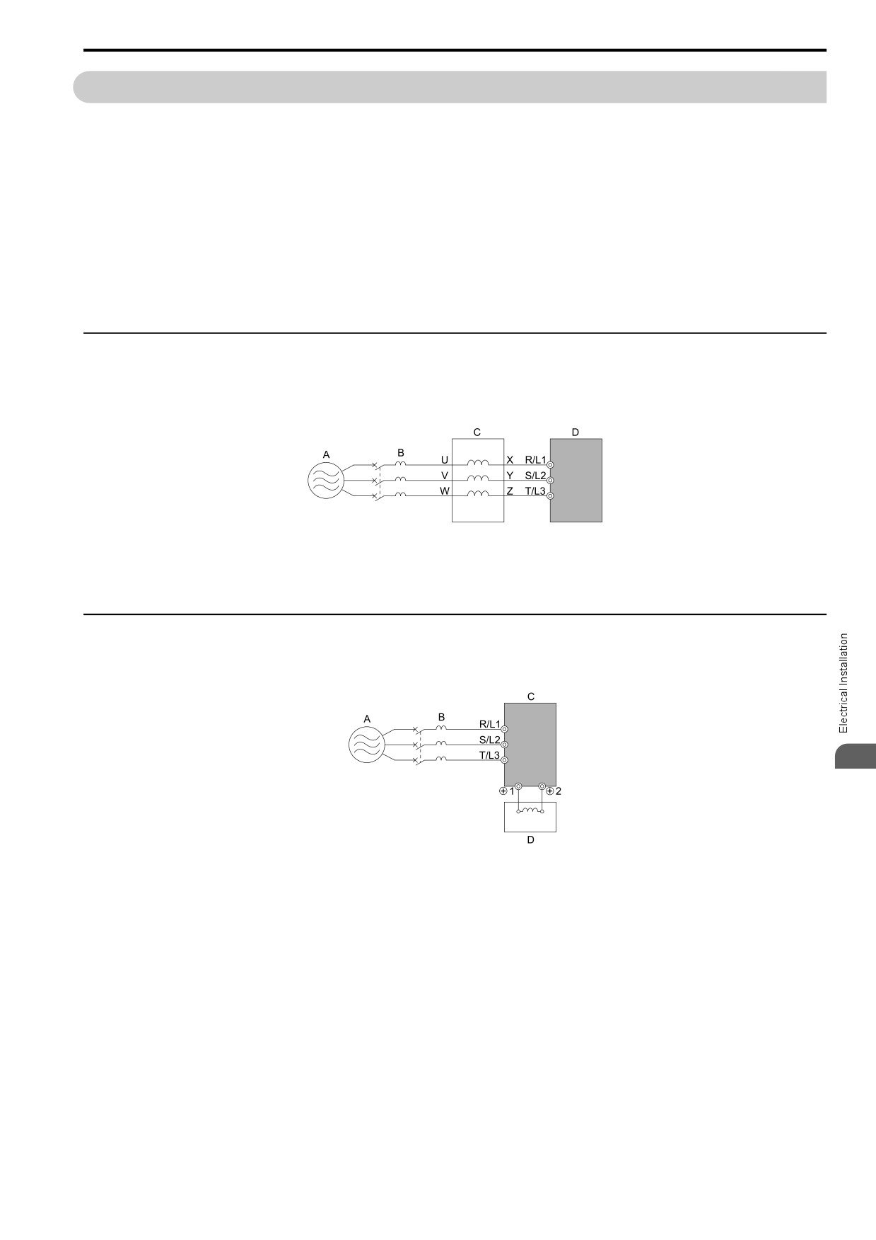
◆ Connect an AC Reactor
Note:
When you connect an AC reactor to the output side (secondary side) of the driver, set C6-02 = 1 [Carrier Frequency Selection = 2.0
kHz].
A - Power supply
C - AC reactor
B - MCCB
D - Drive
Figure 3.40 AC Reactor Connection Example
◆ Connect a DC Reactor
When you install a DC reactor, remove the jumper between terminals +1 and +2. If you will not use a DC link
choke, do not remove the jumper.
3
A - Power supply
C - Drive
B - MCCB
D - DC reactor
Figure 3.41 DC Reactor Connection Example
Note:
You cannot connect a DC reactor to drive models B001 to B018.
91
3.13 Prevent Switching Surge
3.13
Prevent Switching Surge
◆ Connect a Surge Protective Device
A surge protective device decreases the surge voltage that is generated from switching an inductive load near the
drive. Inductive loads include:
• Magnetic contactors
• Electromagnetic relays
• Magnetic valves
• Solenoids
• Magnetic brakes.
Always use a surge protective device or diode with inductive loads.
Note:
Do not connect a surge protective device to the drive output side.
92
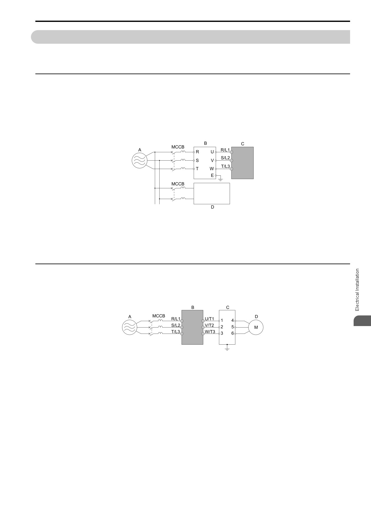
3.14 Decrease Noise
3.14
Decrease Noise
Note:
The main circuit terminal block for the drive and the terminal block for the noise filter come in different shapes. Use caution when you
prepare the ends of the wires.
◆ Connect a Noise Filter to the Input Side (Primary Side)
High-speed switching makes noise in the drive output. This noise flows from the drive to the power supply, and
can possibly have an effect on other equipment. Install a noise filter to the input side of the drive to decrease the
quantity of noise that flows to the power supply. A noise filter also prevents noise from entering the drive from the
power supply.
• Use a noise filter specially designed for drives.
• Install the noise filter as close as possible to the drive.
A - Power supply
C - Drive
B - Input side (primary side) noise filter
D - Other controller
Note:
The input side (primary side) noise filter model is LNFD-xx.
Figure 3.42 Example of Connecting the Noise Filter on the Input Side (Primary Side)
◆ Connect a Noise Filter to the Output Side (Secondary Side)
A noise filter on the output side of the drive decreases inductive noise and radio frequency interference.
NOTICE: Do not connect phase-advancing capacitors, LC/RC noise filters, or leakage breakers (RCM/RCD) to the motor
circuit. If you connect these devices to the output circuits, it can cause damage to the drive and connected equipment.
3
A - Power supply
C - Noise filter on output side (secondary side)
B - Drive
D - Motor
Figure 3.43 Example of Connecting the Noise Filter on the Output Side (Secondary Side)
Note:
Glossary
• Radio frequency interference:
Electromagnetic waves radiated from the drive and cables make noise through the full radio bandwidth that can have an effect on
nearby devices.
• Inductive noise:
The noise from electromagnetic induction can have an effect on the signal line and can cause the controller to malfunction.
■ Prevent Inductive Noise
In addition to installing a noise filter, you can also run all wiring through a grounded metal conduit to decrease
inductive noise occurring at the output side. Put the cables a minimum of 30 cm (11.8 in) away from the signal
line to prevent induced noise. Ground the cables to metal conduits.
93
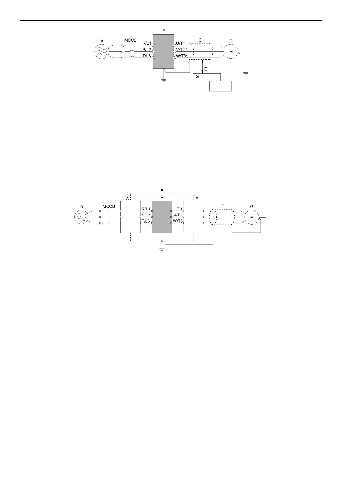
3.14 Decrease Noise
A - Power supply
E - Minimum of 30 cm (11.8 in) apart
B - Drive
F - Controller
C - Shielded motor cable
G - Signal line
D - Motor
Figure 3.44 Prevent Inductive Noise
■ Decrease Radio Frequency Interference
The drive, input lines, and output lines generate radio frequency interference. Use noise filters on input and output
sides and install the drive in a steel box to decrease radio frequency interference.
Note:
Keep the cable between the drive and motor as short as possible.
A - Steel box
E - Noise filter
B - Power supply
F - Shielded motor cable
C - Noise filter
G - Motor
D - Drive
Figure 3.45 Decrease Radio Frequency Interference
94
3.15 Protect the Drive during Failures
3.15
Protect the Drive during Failures
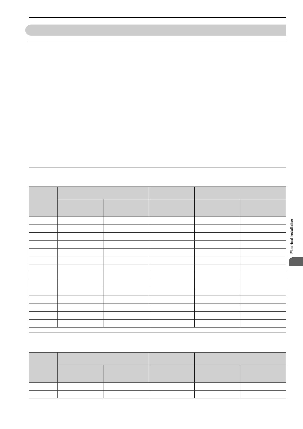
◆ Factory-Recommended Branch Circuit Protection for UL Listing
Use branch circuit protection to protect against short circuits and to maintain compliance with UL61800-5-1. The
manufacturer recommends connecting semiconductor protection fuses on the input side for branch circuit
protection. Refer to Three-Phase 400 V Class on page 96, Single-Phase 200 V Class on page 95, and Three-Phase
200 V Class on page 95 for more information.
WARNING! Electrical Shock Hazard. After the drive blows a fuse or trips an RCM/RCD, do not immediately energize the drive
or operate peripheral devices. Wait for the time specified on the warning label at a minimum and make sure that all indicators
are OFF. Then check the wiring and peripheral device ratings to find the cause of the problem. If you do not know the cause of
the problem, contact the manufacturer before you energize the drive or peripheral devices. If you do not fix the problem before
you operate the drive or peripheral devices, it can cause serious injury or death.
•
200 V class
Use the fuses specified in this document to prepare the drive for use on a circuit that supplies not more than
31,000 RMS and not more than 240 Vac when there is a short circuit in the power supply.
•
400 V class
Use the fuses specified in this document to prepare the drive for use on a circuit that supplies not more than
31,000 RMS and not more than 480 Vac when there is a short circuit in the power supply.
The built-in short circuit protection of the drive does not provide branch circuit protection. The user must provide
branch circuit protection as specified by the National Electric Code (NEC), the Canadian Electric Code, Part I
(CEC), and local codes.
◆ Three-Phase 200 V Class
Table 3.20 Factory-Recommended Branch Circuit Protection: Three-Phase 200 V Class
Maximum Applicable Motor Output
Semiconductor Protection Fuse Rated Current
Time Delay Fuse
kW (HP)
Manufacturer: EATON/Bussmann
Drive Model
Class J, CC, and T Fuse
Input Rated Current
ND
HD
Rated Current
Model
A
A
2001
0.18
(1/6)
0.1
(1/6)
3
FWH-25A14F
25
2002
0.37
(1/4)
0.25
(1/4)
6
FWH-25A14F
25
2004
0.75
(3/4)
0.55
(1/2)
6
FWH-25A14F
25
2006
1.1
(1.5)
0.75
(1)
10
FWH-25A14F
25
2008
1.5
(2)
1.1
(1.5)
15
FWH-70B
70
2010
2.2
(3)
1.5
(2)
20
FWH-70B
70
3
2012
3.0
(4)
2.2
(3)
25
FWH-70B
70
2018
3.7
(5)
3.0
(4)
30
FWH-90B
90
2021
5.5
(5)
4.0
(5)
40
FWH-90B
90
2030
7.5
(10)
5.5
(7.5)
-
FWH-100B
100
2042
11
(15)
7.5
(10)
-
FWH-150B
150
2056
15
(20)
11
(15)
-
FWH-200B
200
2070
18.5
(25)
15
(20)
-
FWH-200B
200
2082
22
(30)
18.5
(25)
-
FWH-225A
225
◆ Single-Phase 200 V Class
Table 3.21 Factory-Recommended Branch Circuit Protection: Single-Phase 200 V Class
Maximum Applicable Motor Output
Semiconductor Protection Fuse Rated Current
Time Delay Fuse
kW (HP)
Manufacturer: EATON/Bussmann
Drive Model
Class J, T, and CC Fuse
Input Rated Current
ND
HD
Rated Current
Model
A
A
B001
0.18
(1/6)
0.1
(1/6)
3
FWH-25A14F
25
B002
0.37
(1/4)
0.25
(1/4)
6
FWH-25A14F
25
95
3.15 Protect the Drive during Failures
Maximum Applicable Motor Output
Semiconductor Protection Fuse Rated Current
Time Delay Fuse
kW (HP)
Manufacturer: EATON/Bussmann
Drive Model
Class J, T, and CC Fuse
Input Rated Current
ND
HD
Rated Current
Model
A
A
B004
0.75
(3/4)
0.55
(1/2)
10
FWH-60B
60
B006
1.1
(1.5)
1.1
(1)
15
FWH-80B
80
B010
2.2
(3)
1.5
(2)
25
FWH-100B
100
B012
3.0
(3)
2.2
(3)
30
FWH-125B
125
B018
-
4.0
(5)
-
FWH-150B
150
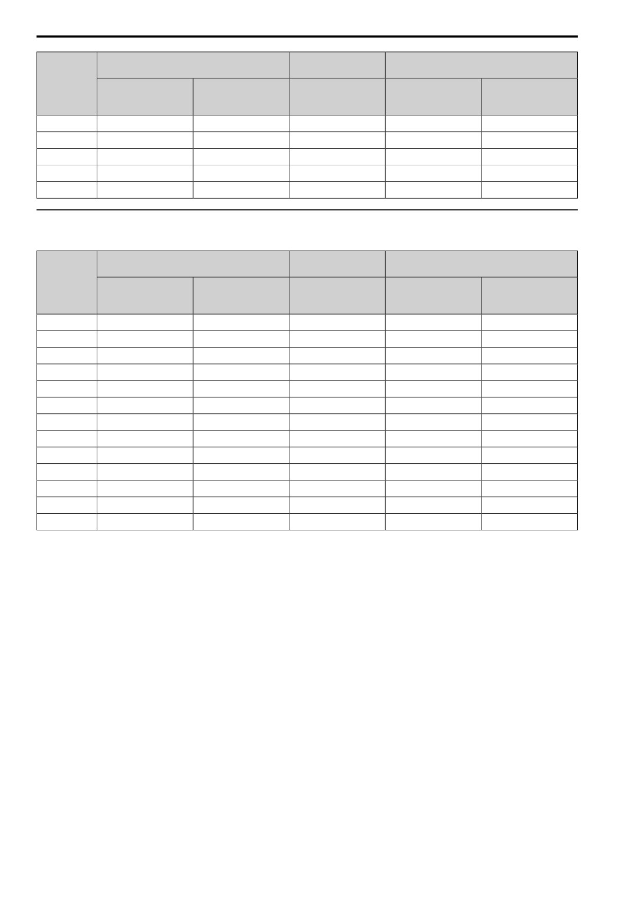
◆ Three-Phase 400 V Class
Table 3.22 Factory-Recommended Branch Circuit Protection: Three-Phase 400 V Class
Maximum Applicable Motor Output
Semiconductor Protection Fuse Rated Current
Time Delay Fuse
kW (HP)
Manufacturer: EATON/Bussmann
Drive Model
Class J, CC, and T Fuse
Input Rated Current
ND
HD
Rated Current
Model
A
A
4001
0.37
(1/2)
0.37
(1/2)
3
FWH-40B
40
4002
0.75
(1)
0.55
(3/4)
6
FWH-40B
40
4004
1.5
(2)
1.1
(2)
10
FWH-50B
50
4005
2.2
(3)
1.5
(3)
10
FWH-70B
70
4007
3.0
(4)
2.2
(3)
15
FWH-70B
70
4009
4.0
(5)
3.0
(4)
20
FWH-90B
90
4012
5.5
(7.5)
4.0
(5)
25
FWH-90B
90
4018
7.5
(10)
5.5
(10)
-
FWH-80B
80
4023
11.0
(15)
7.5
(10)
-
FWH-100B
100
4031
15.0
(20)
11.0
(15)
-
FWH-125B
125
4038
18.5
(25)
15.0
(20)
-
FWH-175B
175
4044
22.0
(30)
18.5
(25)
-
FWH-200B
200
4060
30.0
(40)
22.0
(30)
-
FWH-200B
200
96
3.16 Wiring Checklist
3.16
Wiring Checklist
Wire the drive, examine these items, then do a test run.
Table 3.23 Power Supply Voltage
Checked
No.
Item to Check
1
The power supply voltage must be in the input voltage specification range of the drive.
Table 3.24 Main Circuit Wiring
Checked
No.
Item to Check
1
• Put the power supply through a molded-case circuit breaker (MCCB) before it gets to the drive input.
• Connect an applicable MCCB.
2
Correctly wire the power supply to drive terminals R/L1, S/L2, T/L3, L/L1, and N/L2.
3
Correctly wire the drive and motor together.
The motor lines and drive output terminals U/T1, V/T2, and W/T3 must align to make the correct phase order.
Note:
If the phase order is incorrect, the drive will rotate in the opposite direction.
4
Use 600 V heat resistant indoor PVC wire for the power supply and motor lines.
Note:
Wire gauge recommendations assume use of 600 V class 2 heat-resistant indoor PVC wire.
5
Use the correct wire gauges for the main circuit.
Note:
• When the wiring distance between the drive and the motor is long, use this formula for the voltage drop in the wire:
Motor rated voltage (V) × 0.02 ≥ √3 × wire resistance (Ω/km) × wiring distance (m) × motor rated current (A) × 10-3
• When the cable between the drive and motor is longer than 50 m (164 ft), use parameter C6-02 [Carrier Frequency
Selection] to decrease the carrier frequency.
6
Correctly ground the drive.
7
Tighten the main circuit and grounding terminal screws of the drive to a correct tightening torque.
8
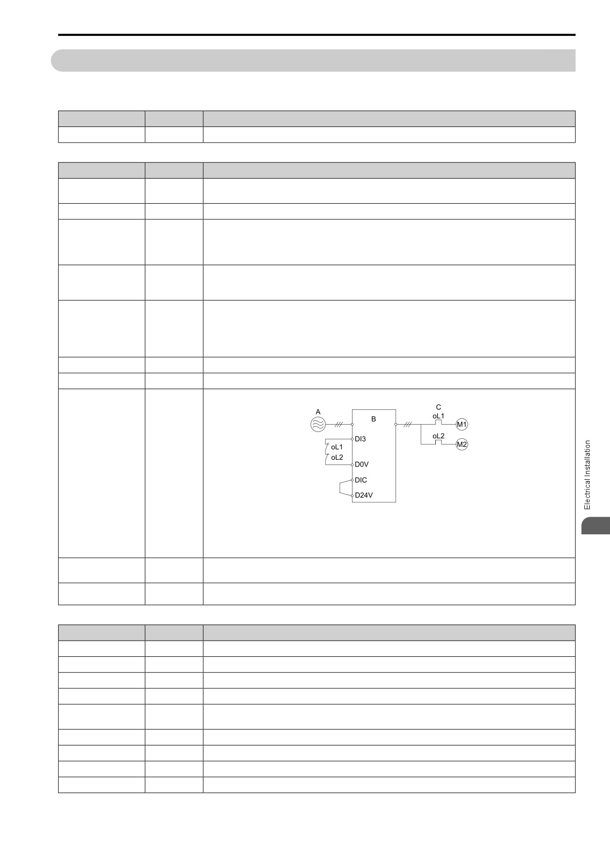
When operating more than one motor from one drive, set up overload protection circuits.
A - Power supply
C - oL1, oL2: Thermal overload
relay
3
B - Drive
Note:
Set H1-03 = 25 [DI3 Function Selection = ExF NC-AlCoast].
9
When you use a braking resistor or a braking resistor unit, install an electromagnetic contactor (MC).
Correctly install the resistor and make sure that overload protection uses the MC to shut off the power supply.
10
Make sure you did not install phase advancing capacitors, input noise filters, or ELCBs, GFCIs, RCM/RCDs on the output side
of the drive.
Table 3.25 Control Circuit Wiring
Checked
No.
Item to Check
1
Use twisted-pair cables for all drive control circuit wiring.
2
Ground the shields of shielded wiring to terminal GND.
3
For 3-Wire sequence, set parameters for MFDI terminals and wire control circuits.
4
Correctly install any options.
5
Examine the drive for other wiring errors.
Only use a multimeter to check wiring.
6
Tighten the control circuit terminal screws of the drive to a correct tightening torque.
7
Pick up all wire clippings.
8
Make sure that none of the wires on the terminal block touch other terminals or connections.
9
Make sure that you isolate the control circuit wiring from main circuit wiring in the control panel or in a duct.
97
3.16 Wiring Checklist
Checked
No.
Item to Check
10
Make sure that control circuit wiring is not longer than 50 m (164 ft).
11
Make sure that Safe Disable input wiring is not longer than 30 m (98 ft).
98
3.17 Motor Application Precautions
3.17
Motor Application Precautions
◆ Precautions for Existing Standard Motors
■ Low-Speed Range
When a drive operates a standard motor, it will lose more power compared to operating the motor with a
commercial power supply. In the low speed range, the temperature of the motor increases quickly because the
motor cannot decrease its temperature when the speed decreases. In these conditions, decrease the load torque of
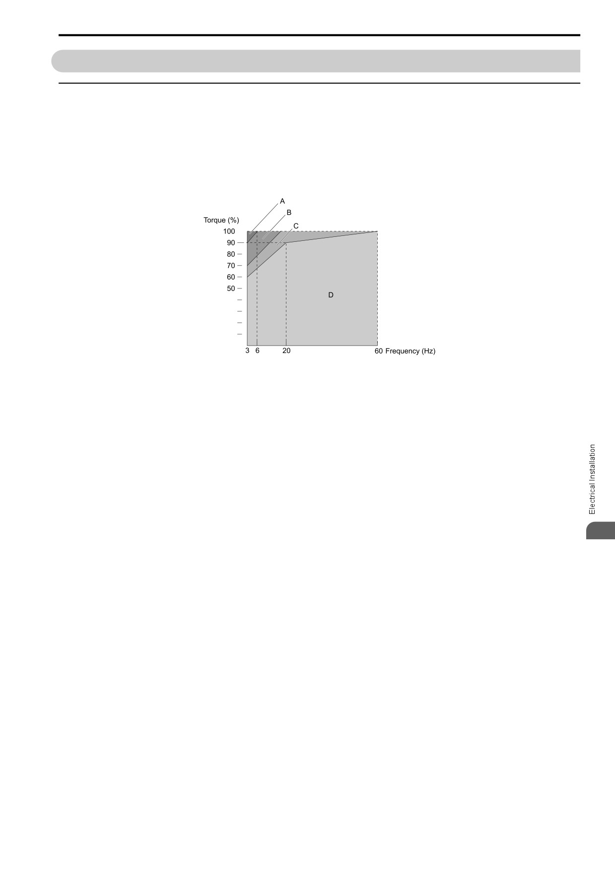
the motor in the low-speed range. Figure 3.46 shows the permitted load characteristics for a Yaskawa standard
motor. When 100% continuous torque is necessary at low speeds, use a motor designed to operate with a drive.
A - 25% ED (or 15 min)
C - 60% ED (or 40 min)
B - 40% ED (or 20 min)
D - Continuous operation
Figure 3.46 Permitted Load Characteristics for a Yaskawa Standard Motors
■ Insulation Withstand Voltage
Consider motor voltage tolerance levels and motor insulation in applications with an input voltage of over 440 V
or particularly long wiring distances. Use an insulated drive motor.
NOTICE: Use an inverter-duty motor or vector-duty motor with reinforced insulation and windings applicable for use with an AC
drive. If the motor does not have the correct insulation, it can cause a short circuit or ground fault from insulation deterioration.
■ High-Speed Operation
If you operate a motor more than its rated speed, you can have problems with the motor bearing durability and
dynamic balance of the machine. Contact the motor or machine manufacturer.
3
■ Torque Characteristics
When you operate a motor with a drive, the torque characteristics are different than when you operate the motor
directly from line power. Make sure that you know about the load torque characteristics for your application.
■ Vibration
Vibrations could occur in the these conditions:
• Resonance with the natural frequency of machinery
Use caution if you add a variable-speed drive to applications that operate the motor from line power at a
constant speed. If resonance occurs, install shock-absorbing rubber around the base of the motor and enable the
Jump frequency control.
• The motor is not balanced
Use caution if the motor speed is more than the rated motor speed.
• Subsynchronous resonance
Subsynchronous resonance can occur with long motor shafts and in applications such as turbines, blowers, and
fans with high inertia loads.
99
3.17 Motor Application Precautions
■ Audible Noise
The audible noise of the motor changes when the carrier frequency setting changes. When you use a high carrier
frequency, audible noise from the motor is equivalent to the motor noise generated when you operate from line
power. If you operate at speeds that are more than the rated rotation speed, the unwanted motor noise increases.
◆ Precautions for PM Motors
•
Contact the manufacturer or your nearest sales representative to use a PM motor that is not from the drive
manufacturer.
•
You cannot operate a PM motor from a commercial power supply. If you must operate from a commercial
power supply, use an induction motor.
•
You cannot operate more than one PM motor from one drive. Use an induction motor and a variable-speed
control drive.
•
In OLV/PM, the motor can operate in the reverse direction for 1/2 turn (electrical angle) at start up.
•
The quantity of generated starting torque changes when the control method and motor type change. Verify the
starting torque, permitted load characteristics, impact load tolerance, and speed control range before you set up
the motor with the drive. Contact the manufacturer or your nearest sales representative to use a motor that does
not meet these specifications.
•
In OLV/PM control, braking torque is always 125% or less when operating between 20% and 100% speed. A
braking resistor unit will not change the value. Braking torque is 50% or less when operating at 20% speed or
less.
•
When you use a holding brake in OLV/PM control, release the brake before you start the motor. Failure to set
the correct timing can cause a decrease in speed. Do not use these configurations in applications with heavy
loads, for example conveyors or elevators.
•
To restart a coasting motor that is rotating faster than 120 Hz, first use the Short Circuit Braking function to stop
the motor. A special braking resistor unit is necessary for Short Circuit Braking. Contact the manufacturer or
your nearest sales representative for more information.
To restart a coasting motor that is rotating slower than 120 Hz, use the Speed Search function.
If the motor cable is long, use Short Circuit Braking to stop the motor.
Note:
The Short Circuit Braking function uses the drive to forcefully cause a short across the motor wires to stop the motor before it has time
to coast to a stop.
•
You can also use EZOLV to operate synchronous reluctance motors (SynRM). Contact the manufacturer or your
nearest sales representative for more information.
•
If oC [Overcurrent], STPo [Motor Step-Out Detected], or LSo [Low Speed Motor Step-Out] occur during
restart, try Speed Search again and use the Short Circuit Braking function when you start to adjust the motor.
◆ Precautions for Specialized Motors
■ Pole Change Motors
The rated current of pole change motors is different than standard motors. Check the maximum current of the
motor before you select a drive. Always stop the motor before you switch between the number of motor poles. If
you change the number of poles while the motor is rotating, the overvoltage from regeneration or the overcurrent
protection circuitry will make the motor coast to stop.
■ Submersible Motors
The rated current of a submersible motor is more than the rated current of a standard motor. Use a sufficiently
large motor cable that will not let voltage drop decrease the maximum torque level.
■ Explosion-Proof Motors
You must test the motor and the drive together for explosion-proof certification. You must also test existing
installations of explosion-proof motors. The drive is not designed for explosion-proof areas. Install the drive in a
safe location.
The encoder used with pressure-resistant explosion-proof motors is intrinsically safe. When wiring between the
drive and encoder, always connect through a specialized pulse coupler.
100
3.17 Motor Application Precautions
■ Geared Motors
The continuous speed range is different for different lubricating methods and manufacturers. For oil lubrication,
continuous operation in the low-speed range can cause burnout. Contact the manufacturer for more information
about applications where operating at more than the rated frequency is necessary.
■ Single-Phase Motors
Variable speed drives are not designed to operate with single-phase motors. The drive is for use with three-phase
motors only. If you use capacitors to start the motor, it can cause a high frequency current to flow to the capacitors
and can damage the capacitors. A split-phase start or a repulsion start can burn out the starter coils because the
internal centrifugal switch is not activated.
■ Motors with Brakes
If you use a drive to operate a motor that has a brake connected to the output side, low voltage levels can cause
the brake to possibly not release at start. Use a motor with a brake that has a dedicated source of power for the
brake. Connect the brake power supply to the power supply side of the drive. Motors with built-in brakes make
noise when operating at low speeds.
◆ Notes on the Power Transmission Mechanism
For power transmission machinery that uses oil to lubricate gearboxes, transmissions, or reduction gears, make
sure that you use precaution if you operate the machinery continuously at low speed. Oil does not lubricate the
system as well at low speeds. If you operate at frequencies higher than the rated frequency, it can cause problems
with the power transmission mechanism. These problems include audible noise, decreased service life, and
decreased durability.
3
101
3.17 Motor Application Precautions
102
4
Startup Procedure and Test Run
4.1
Safety Precautions
104
4.2
Component Names and Functions
105
4.3
Set up the Drive with Manual Setup Mode
108
4.4
Drive Mode and Programming Mode
109
4.5
Start-up Procedures
113
4.6
Items to Check before Starting Up the Drive
117
4.7
Keypad Operation
118
4.8
Automatic Parameter Settings Optimized for Specific Applications
(Application Presets)
123
4.9
Auto-Tuning
124
4.10
Test Run
130
4.11
Fine Tuning during Test Runs (Adjust the Control Function)
132
4.12
Test Run Checklist
136
103
4.1 Safety Precautions
4.1
Safety Precautions
DANGER
Electrical Shock Hazard
Do not examine, connect, or disconnect wiring on an energized drive. Before servicing,
disconnect all power to the equipment and wait for the time specified on the warning label at a
minimum. The internal capacitor stays charged after the drive is de-energized. The charge
indicator LED extinguishes when the DC bus voltage decreases below 50 Vdc. When all
indicators are OFF, measure for dangerous voltages to make sure that the drive is safe.
If you do work on the drive when it is energized, it will cause serious injury or death from electrical shock. The
drive has internal capacitors that stay charged after you de-energize the drive.
WARNING
Electrical Shock Hazard
Do not operate the drive when covers are missing. Replace covers and shields before you
operate the drive. Use the drive only as specified by the instructions.
Some figures in this section include drives without covers or safety shields to more clearly show the inside of the
drive. If covers or safety shields are missing from the drive, it can cause serous injury or death.
Do not remove covers or touch circuit boards while the drive is energized.
If you touch the internal components of an energized drive, it can cause serious injury or death.
Sudden Movement Hazard
When you use a mechanical holding brake with the drive in a lifting application, you must close
the brake if an input terminal triggers the Baseblock command to stop drive output.
If you enter the baseblock command, the motor will suddenly coast and the load will slip, which can cause
serious injury or death.
When you use the drive in a lifting application, you must also install external safety circuitry.
The drive does not have protection against accidental load drops in lifting applications. Install
electrical and/or mechanical safety circuit mechanisms that are isolated from the drive circuitry.
If you do not use external safety circuitry, the drive could drop the load and cause serious injury or death.
104
4.2 Component Names and Functions
4.2
Component Names and Functions
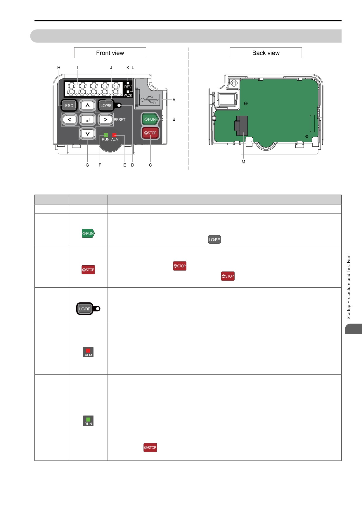
Figure 4.1 Keypad
Table 4.1 Keypad: Names and Functions
Symbol
Name
Function
A
USB Terminal
Insertion point for a USB cable. Uses a USB cable (USB standard 2.0, type A - mini-B) to connect the keypad to a PC.
Starts the drive in LOCAL Mode.
RUN Key
Starts the operation in Auto-Tuning Mode.
B
Note:
Before you use the keypad to operate the motor, push
on the keypad to set the drive to LOCAL Mode.
Stops drive operation.
Note:
STOP Key
C
Uses a stop-priority circuit. Push
to stop the motor. This will also stop the motor when a Run command is active at an
external Run command source (REMOTE Mode). To disable
priority, set o2-02 = 0 [STOP Key Selection of Function =
Disabled].
Illuminated: The keypad controls the Run command (LOCAL Mode).
LO/RE LED
OFF: The control circuit terminal or serial transmission device controls the Run command (REMOTE Mode).
D
Note:
• LOCAL: Operated using the keypad. Use the keypad to enter Run/Stop commands and the frequency reference command.
• REMOTE: Operated from the control circuit terminal or serial transmission. Use the frequency reference source entered in b1-01
and the Run command source selected in b1-02.
Illuminated: The drive detects a fault.
4
OFF: There are no drive faults or alarms.
Flashing:
ALM/ERR LED
• An alarm
E
• Operation Errors
• An Auto-Tuning error
Note:
The LED will illuminate to identify a fault if the drive detects a fault and an alarm at the same time.
Illuminated: The drive is in regular operation.
OFF: The drive is stopped.
Flashing:
• The drive is decelerating to stop.
• The drive received a Run command, but the frequency reference is 0 Hz.
Flashing quickly:
RUN LED
F
• The drive received a Run command from the MFDI terminals and is switching to REMOTE Mode while the drive is in LOCAL
Mode.
• The drive received a Run command from the MFDI terminals when the drive is not in Drive Mode.
• The drive received a Fast Stop command.
• The safety function shuts off the drive output.
• The user pushed
on the keypad while the drive is operating in REMOTE Mode.
• The drive is energized with an active Run command and b1-17 = 1 [RUN@PowerUp Selection = Disregard RUN].
105
4.2 Component Names and Functions
Symbol
Name
Function
Left Arrow Key
Moves the cursor to the left.
Up Arrow Key/
• Moves to a different screen.
Down Arrow Key
• Selects parameter numbers and increments or decrements setting values.
/
G
Right Arrow Key
• Moves the cursor to the right.
(RESET)
• Restarts the drive to clear a fault.
ENTER Key
• Enters parameter values and settings.
• Selects each mode, parameter, and set value.
ESC Key
• Goes back to the previous screen.
H
• Push and hold to go back to the frequency reference screen (the initial screen).
I
LED Display
Shows parameters, errors, and other data.
Switches drive control for the Run command and frequency reference between the keypad (LOCAL) and an external source
(REMOTE).
LO/RE Selection
Note:
Key
• The LOCAL/REMOTE Selection Key continuously stays enabled after the drive stops in Drive Mode. If the application must not
J
switch from REMOTE to LOCAL because it will have a negative effect on system performance, set o2-01 = 0 [LO/RE Key
Selection of Function = Disabled] to disable
• The drive will not switch between LOCAL and REMOTE when it is receiving a Run command from an external source.
REV LED
Illuminated: The drive received a Reverse run command.
K
PACK LED
Illuminated: The drive is In Q2pack operation.
L
Connects to the drive. Use an RJ-45 8-pin straight through UTP CAT5e extension cable to install the keypad in a different location
M
RJ-45 Connector
than the drive.
WARNING! Sudden Movement Hazard. If you change the control source when b1-07 = 2 [LO/RE Run Selection = Accept RUN],
the drive can start suddenly. Before you change the control source, remove all personnel from the area around the drive, motor,
and load. Sudden starts can cause serious injury or death.
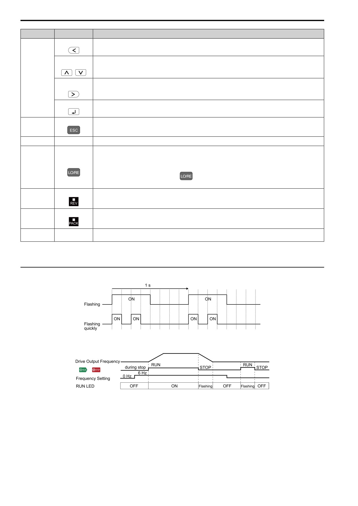
◆ LED Flashing Statuses
Figure 4.2 About indicator flashing statuses
/
Figure 4.3 Relation between RUN indicator and Drive Operation
106
4.2 Component Names and Functions
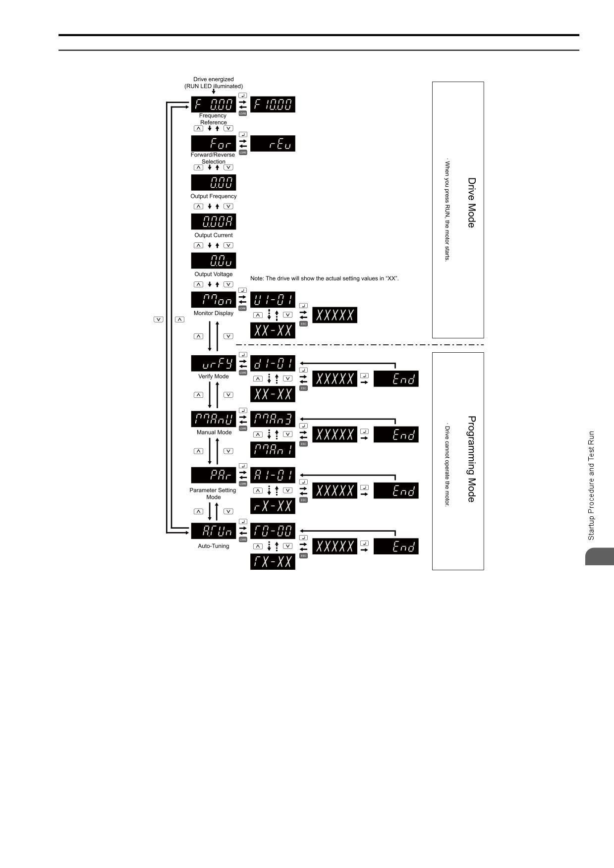
◆ Keypad Mode and Menu Displays
4
107
4.3 Set up the Drive with Manual Setup Mode
4.3
Set up the Drive with Manual Setup Mode
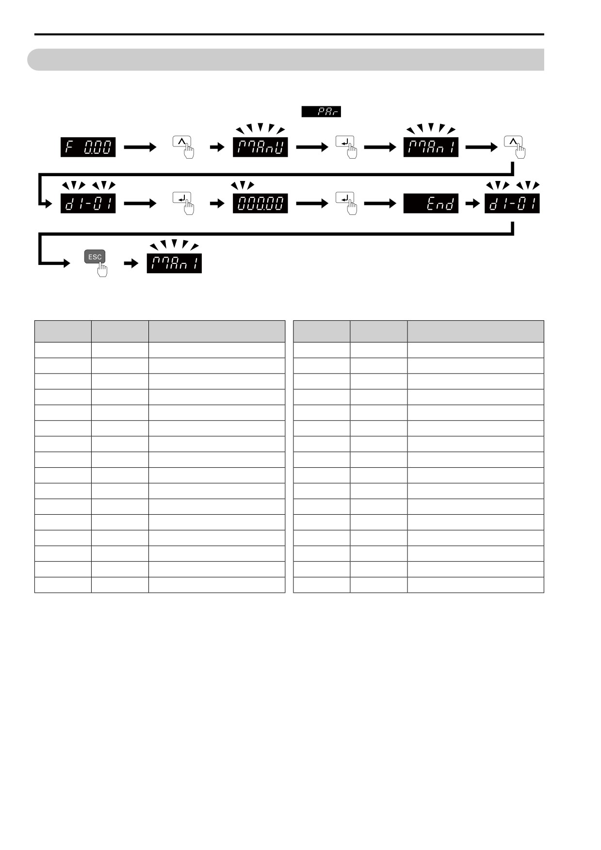
Drive parameters are in letter groups from A to U. Manual Setup Mode contains only the most frequently used
parameters to help you set up the drive more easily.
To access parameters not shown in the Setup Mode, use the
menu.
Figure 4.4 Parameters in Manual Setup Mode
Table 4.2 Parameters in Manual Setup Mode
User
User
Parameter
Name
Parameter
Name
Parameters
Parameters
A2-01
d1-01
Reference 1
A2-17
—
not used
A2-02
C1-01
Accel Time 1
A2-18
—
not used
A2-03
C1-02
Decel Time 1
A2-19
U1-16
SFS Output Frequency
A2-04
U1-01
Frequency Reference
A2-20
U1-05
Motor Speed
A2-05
U1-02
Output Frequency
A2-21
b5-02
Proportional Gain (P)
A2-06
U1-03
Output Current
A2-22
b5-03
Integral Time (I)
A2-07
d1-17
Jog Reference
A2-23
b5-05
Derivative Time (D)
A2-08
b1-01
Freq. Ref. Sel. 1
A2-24
U5-04
PID Setpoint
A2-09
b1-02
Run Comm. Sel 1
A2-25
U5-01
PID Feedback
A2-10
b1-03
Stopping Method Selection
A2-26
b5-01
PID Enable
A2-11
E2-11
Motor Rated Power (kW)
A2-27
b5-18
b5-19 PID SP Selection
A2-12
E2-01
Mot Rated Current (FLA)
A2-28
b5-06
PID Output Limit
A2-13
E2-04
Motor Pole Count
A2-29
b5-70
PID MainRefMode
A2-14
E1-04
Max Output Frequency
A2-30
b5-10
PID Output Gain Setting
A2-15
—
not used
A2-31
b5-11
PID Output Reverse Selection
A2-16
—
not used
A2-32
b5-17
PID Accel/Decel Time
Note:
• When you change A1-02 [Control Method], the settings of some parameters automatically change.
108
4.4 Drive Mode and Programming Mode
4.4
Drive Mode and Programming Mode
The keypad display of this drive has two modes: Drive Mode and Programming Mode.
• Drive Mode
Use this mode to operate the drive. These operations are available:
- Monitor operation statuses (for example, output frequency, output current, and output voltage)
- Set parameters that you can set while the drive is operating (for example, d1-01 to d1-17). Refer to Parameter
Details on page 431 for more information.
• Programming Mode
Use this mode to set parameters. These operations are available:
- Examine and set the parameters that are not at default settings (Verify Mode)
- See and set all parameters (Parameter Setting Mode)
- Automatically set motor parameters (Auto-Tuning Mode)
The following tables give information about the functions you can access when you push
/
Note:
You can use b1-08 [RUN@PRG Mode Selection] to set the drive to accept Run commands from an external source while in
Programming Mode.
• Set b1-08 = 1 [NoRUN@Program] to reject the Run command from an external source while in Programming Mode.
• Set b1-08 = 2 [RUN@Program] to accept the Run command from an external source while in Programming Mode.
• Set b1-08 = 3 [Program@Stop only] to prevent changes from Drive Mode to Programming Mode.
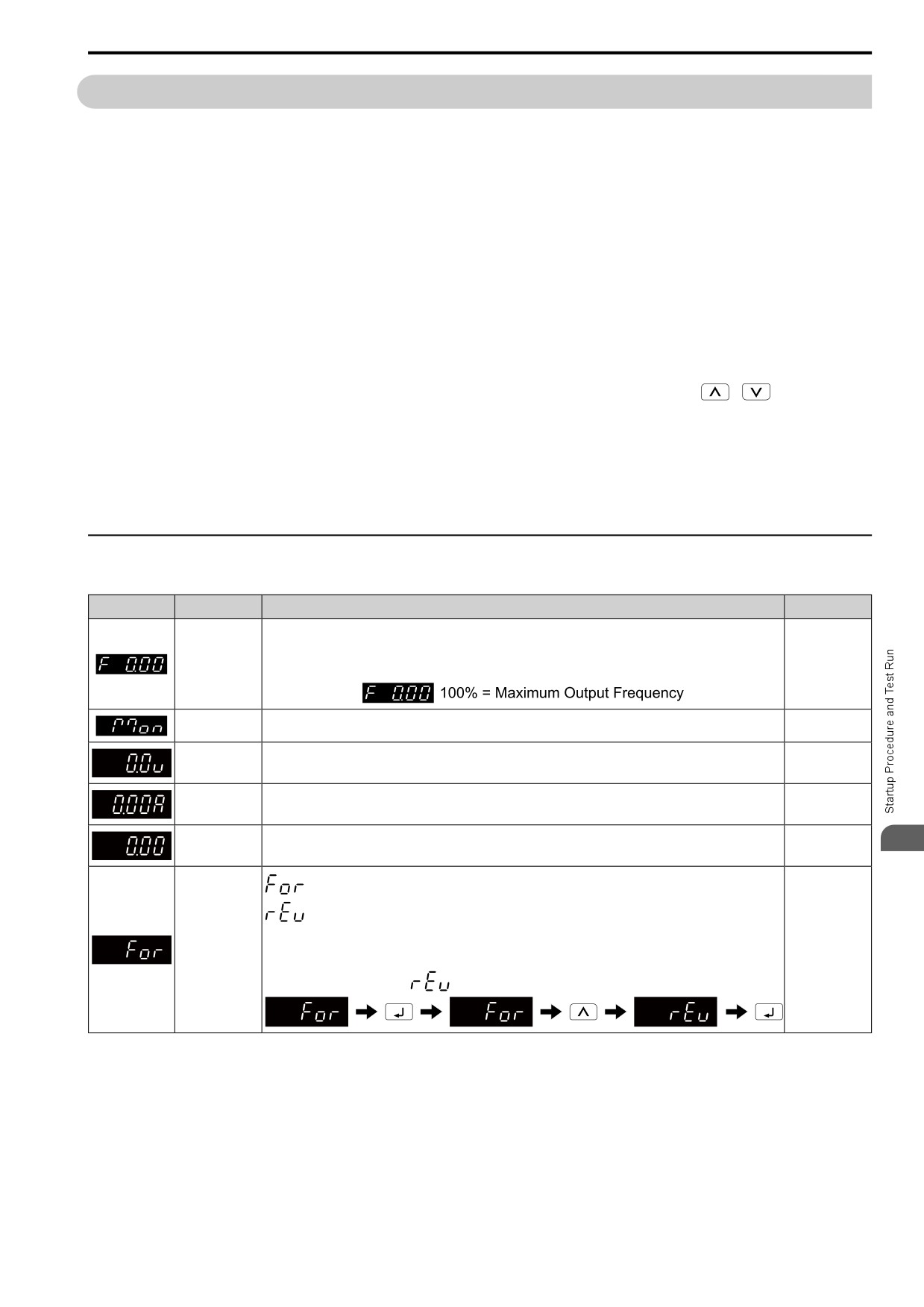
◆ Drive Mode (Operation of the motor and monitoring of operation status)
Table 4.3 Overview of the Modes
LED Display
Description
Description
Ref.
Frequency
You can set and monitor frequency references.
reference display
Note:
You can change what is shown on the keypad when you energize the drive. Use o1-02 [Monitor Selection at
-
Power-up] to set the items. When A1-02 = 6 [Control Method = PM AOLVector], the display unit is %.
Monitor display
The keypad shows Ux-xx [Monitor].
-
Output voltage
You can monitor the output voltage reference.
display
313
Use o1-01 [User Monitor Selection] to change the items shown on this display.
Output current
You can monitor the output current.
display
-
Output frequency
You can monitor the frequency output from the drive.
4
indicator
-
Forward/reverse
selection
: Motor rotates in forward direction
: Motor rotates in reverse direction
Note:
For applications where the motor must not rotate in reverse direction (for example, for fans and pumps), you can
-
use b1-04 [Reverse Operation Selection] to prevent reverse rotation.
How to set reverse operation
109
4.4 Drive Mode and Programming Mode
◆ Programming Mode (Parameter Settings)
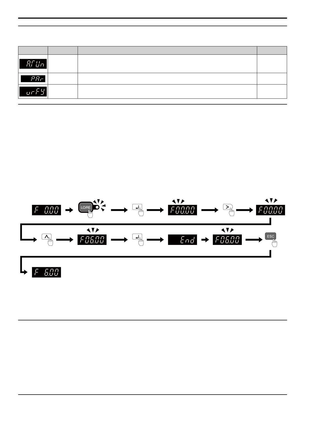
Table 4.4 Overview of the Modes
LED Display
Description
Description
Ref.
Auto-Tuning
The drive automatically calculates and sets the motor parameters.
124
Mode
125
126
Parameter Setting
You can see and set all parameters.
110
Mode
Verify Menu
You can examine and set the parameters that are not at default settings.
111
◆ Drive Mode
These operations are available in Drive Mode:
• Operate and stop the drive
• Show the drive status monitors (for example, frequency reference, output frequency, output current, and output
voltage)
• Show the alarm content
• Show the alarm history
Note:
To operate the drive, select Drive Mode. You can switch to other modes when the drive stops, but the drive must be in Drive Mode to
start operation.
These steps show how to set the frequency reference source to LOCAL (keypad) and change the frequency
reference from 0 Hz to 6 Hz.
Figure 4.5 Frequency Reference Setting in Drive Mode
Note:
To prevent an incorrect setting, after you enter the frequency reference, you must push the ENTER key to change the frequency
reference. Set o2-05 = 1 [LCD FreqRef Mode@Home Screen = Enabled] to change the frequency reference value without pushing the
ENTER key.
◆ Programming Mode
In Programming Mode, you can set parameters or do Auto-Tuning. This mode has 4 sub-modes for different
programming requirements:
• Verify Menu: Use this mode to examine and set the parameters that are not at default settings.
• Setup Mode: Use this mode to see and set the minimum parameters necessary for drive operation. Refer to
Verify and Set the Changed Parameters (Verify Menu) on page 111 for more information.
• Parameter Setting Mode: Use this mode to see and set all parameters.
• Auto-Tuning Mode: Use this mode to automatically set the motor parameters necessary for each control
method.
◆ Change Parameter Settings
Show the frequency reference screen in advance.
110
4.4 Drive Mode and Programming Mode
Note:
Push and hold
to go back to the frequency reference screen from any screen.
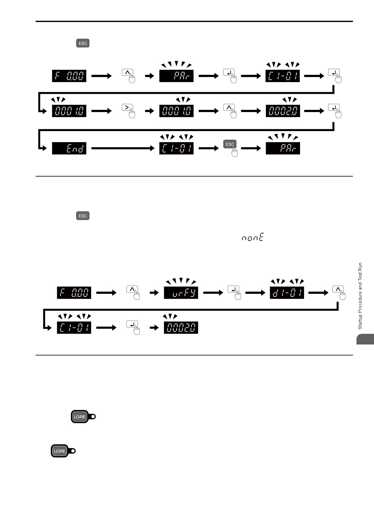
Use these steps to change C1-01 [Accel Time 1] from 1.0 s (default) to 2.0 s.
Figure 4.6 Key Operation Examples for Parameter Settings
◆ Verify and Set the Changed Parameters (Verify Menu)
Show the frequency reference screen in advance.
Note:
Push and hold
to go back to the frequency reference screen from any screen.
Use Verify mode to view all parameters that are not at default settings. This is very useful when you replace a
drive. When there are no changes to parameter settings, the display shows
. This lets you quickly access
and re-edit changed parameters.
Note:
The drive will only display A1-02 [Control Method], A1-xx, A2-01 to A2-32 [MAN1 Param1 to MAN3 Param12], and E5-01 [PM Mot
Code Selection].
4
Figure 4.7 Verify and Set the Changed Parameters
◆ How to Switch between LOCAL and REMOTE
LOCAL mode lets you use the keypad to input Run commands. REMOTE mode lets you use other sources than
the keypad to input Run commands.
WARNING! Sudden Movement Hazard. If you change the control source when b1-07 = 2 [LO/RE Run Selection = Accept RUN],
the drive can start suddenly. Before you change the control source, remove all personnel from the area around the drive, motor,
and load. Sudden starts can cause serious injury or death.
You can use
or MFDI functions (LOCAL/REMOTE Selection) to switch between LOCAL and
REMOTE.
Note:
1.
illuminates while the drive is in LOCAL Mode.
2. While you are entering a Run command, you cannot switch between LOCAL and REMOTE.
111
4.4 Drive Mode and Programming Mode
■ Use the LO/RE Selection Key on the Keypad to Switch between LOCAL and REMOTE
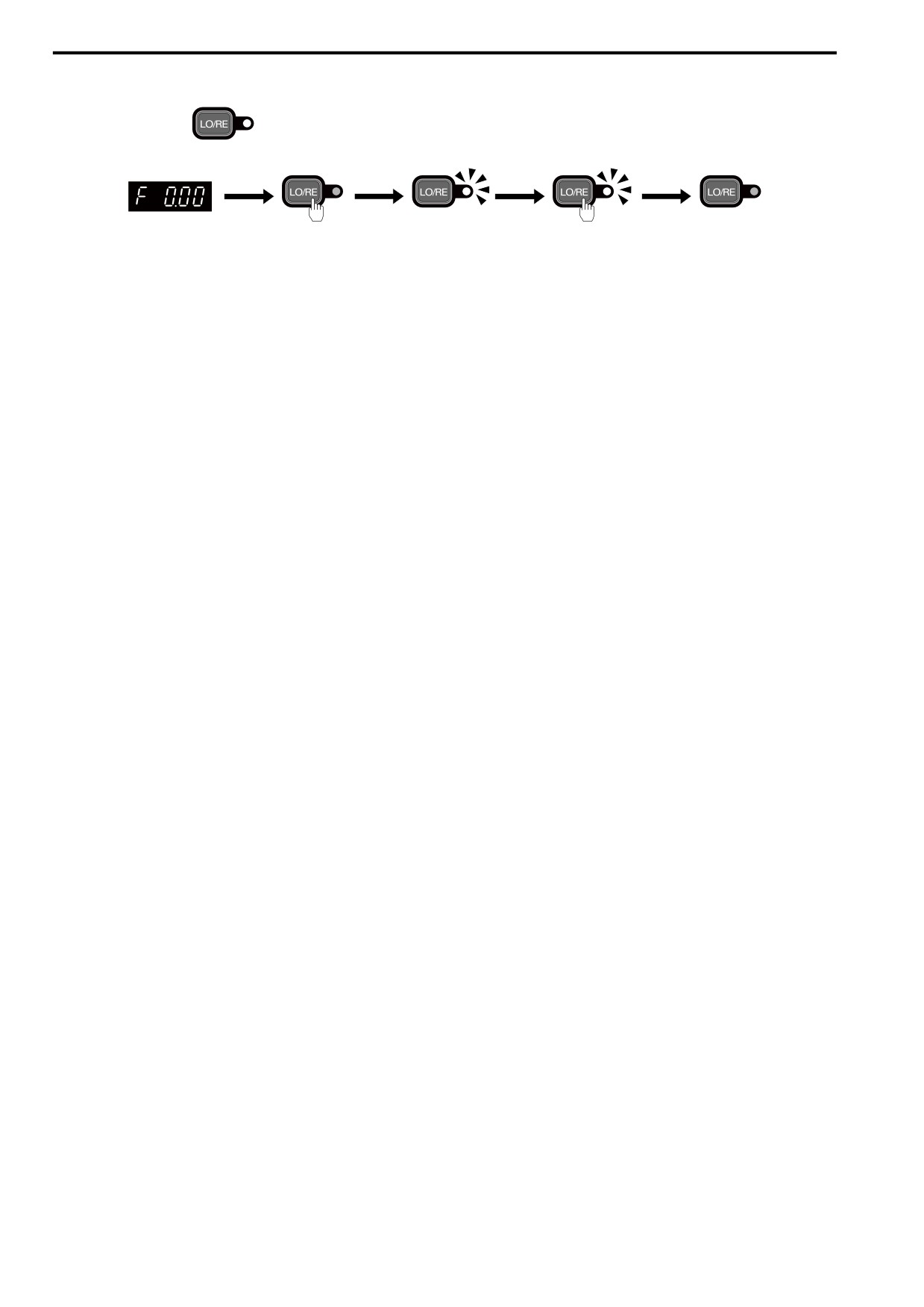
Each time you push
, the mode switches between LOCAL and REMOTE. The LED illuminates in
LOCAL Mode.
Figure 4.8 Use the LO/RE Selection Key to Switch between LOCAL and REMOTE
■ Use MFDI Terminals (DI1 to DI7) to Switch between LOCAL and REMOTE
When you set H1-xx = 11 [MFDI Function Select = LOC/REM Sel.], you can activate/deactivate the terminal to
switch between LOCAL and REMOTE. Set H1-xx = 11 to disable the LO/RE key on the keypad.
112
4.5 Start-up Procedures
4.5
Start-up Procedures
This section gives the basic steps necessary to start up the drive.
Use the flowcharts in this section to find the most applicable start-up method for your application.
This section gives information about only the most basic settings.
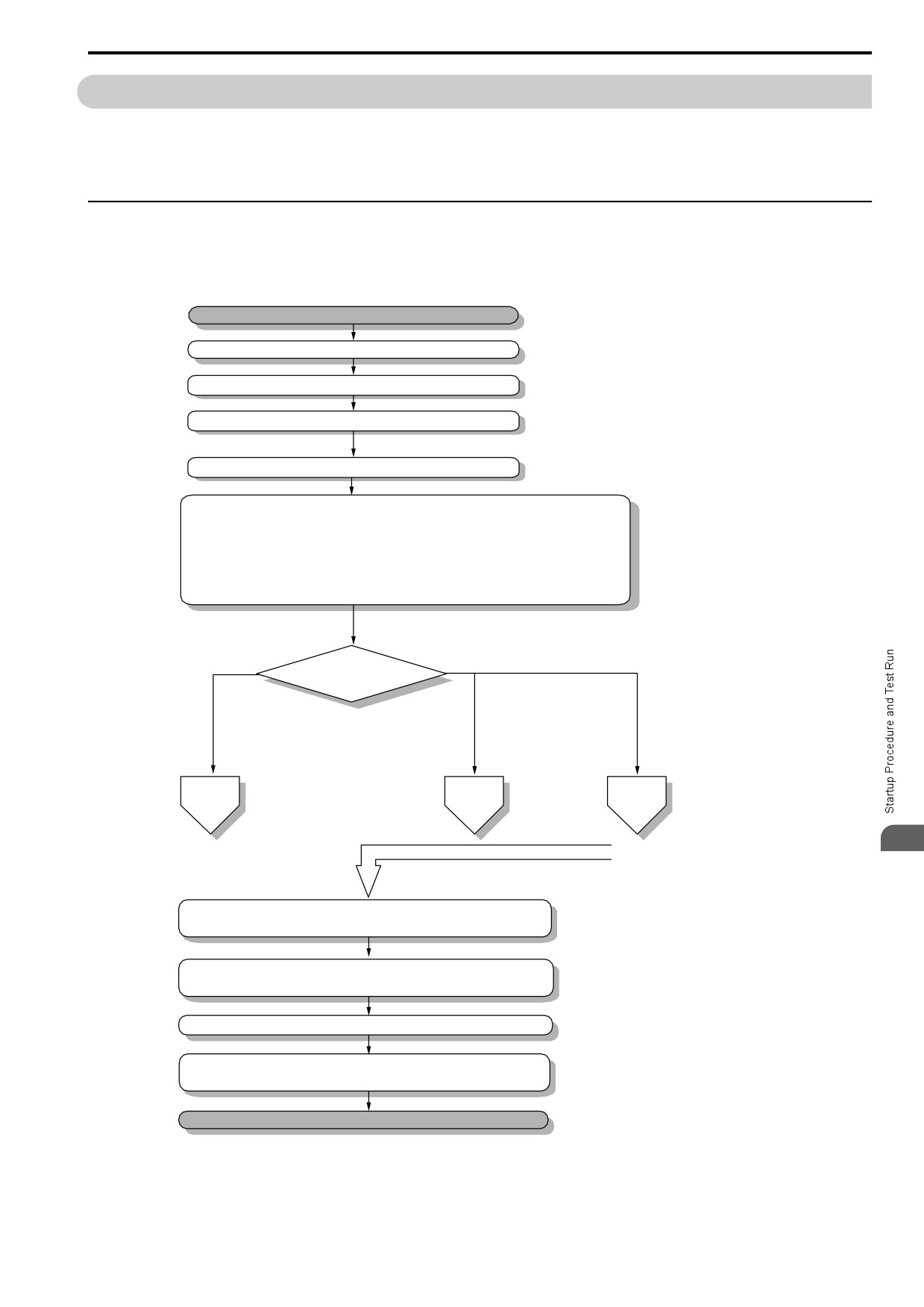
◆ Flowchart A: Connect and Run the Motor with Minimal Setting Changes
Flowchart A shows a basic start-up sequence to connect and run a motor with a minimum of setting changes.
Settings can change when the application changes.
Use the drive default parameter settings for basic applications where high precision is not necessary.
Start
Installation and Wiring
Check before Energizing Drive
Check after Energizing Drive
Set A1-02 [Control Method Selection].
Set the basic parameters.
- Set b1-02 [Run Command Selection] and b1-01 [Frequency Reference Selection]
- Set parameter H1, H2, H3, H4, or H6 to I/O functions
- Set d1-xx when you use multi-step speed
- Set C1-xx and C2-xx for accel/decel time and S-curve characteristics
- Set C6-01 to Heavy duty or Normal duty
- Set L3-04 when you use braking resistors or braking transistors
Control Method Selection
Induction
A1-02 =
PM motor
Induction motor and
motor
PM motor
0: V/f Control
5: Open Loop Vector Control
8: EZ Open
2: Open Loop Vector Control
for PM
Loop Vector Control
6: PM Advanced Open Loop
Vector Control
To
To
To
sub-chart
sub-chart
sub-chart
A-1
A-2
A-3
4
From sub-charts A-1, A-2, A-3
Perform no-load test-run. Make sure the machine operation, direction of
motor rotation, and functioning of multi-functional input/output is correct.
Operate with an actual load. Make sure that
the machine operates as you have set.
Fine tune parameters. Adjust application settings if necessary.
Check he machine operation and use the Verify function to
check the parameter settings.
Drive is ready to run the application.
Figure 4.9 Basic Steps before Startup
113
4.5 Start-up Procedures
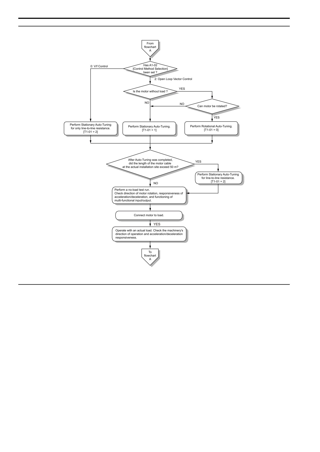
◆ Sub-Chart A-1: Induction Motor Auto-Tuning and Test Run Procedure
Figure 4.10 Induction Motor Auto-Tuning and Test Run Procedure
◆ Sub-Chart A-2: PM Motor Auto-Tuning and Test Run Procedure
Sub-Chart A-2 gives the basic steps to start up the drive for a PM motor.
WARNING! Crush Hazard. Test the system to make sure that the drive operates safely after you wire the drive and set
parameters. If you do not test the system, it can cause damage to equipment or serious injury or death.
114

4.5 Start-up Procedures
Figure 4.11 PM Motor Auto-Tuning and Test Run Procedure
*1
For Yaskawa PM motors (SMRD, SMRA-series, or SSR1-series), set E5-01 [PM Mot Code Selection]. For PM motors from a
different manufacturer, set E5-01 = FFFF.
◆ Sub-Chart A-3: EZ Open Loop Vector Control Test Run Procedure
4
Sub-chart A-3 gives the setup procedure to run a PM motor in EZ Open Loop Vector Control.
115
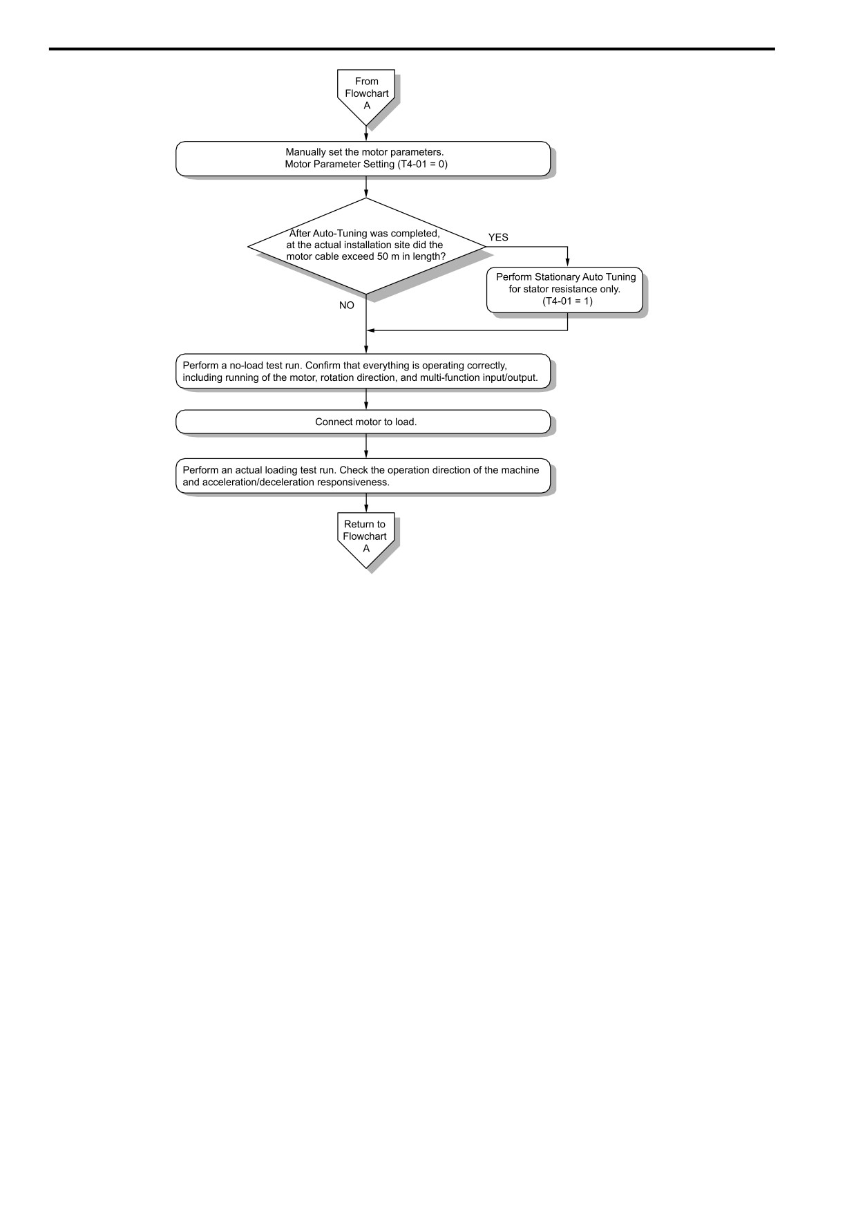
4.5 Start-up Procedures
Figure 4.12 Procedure for Test Run of EZ Open Loop Vector Control Method
116
4.6 Items to Check before Starting Up the Drive
4.6
Items to Check before Starting Up the Drive
◆ Check before You Energize the Drive
Check the following items before you energize the drive.
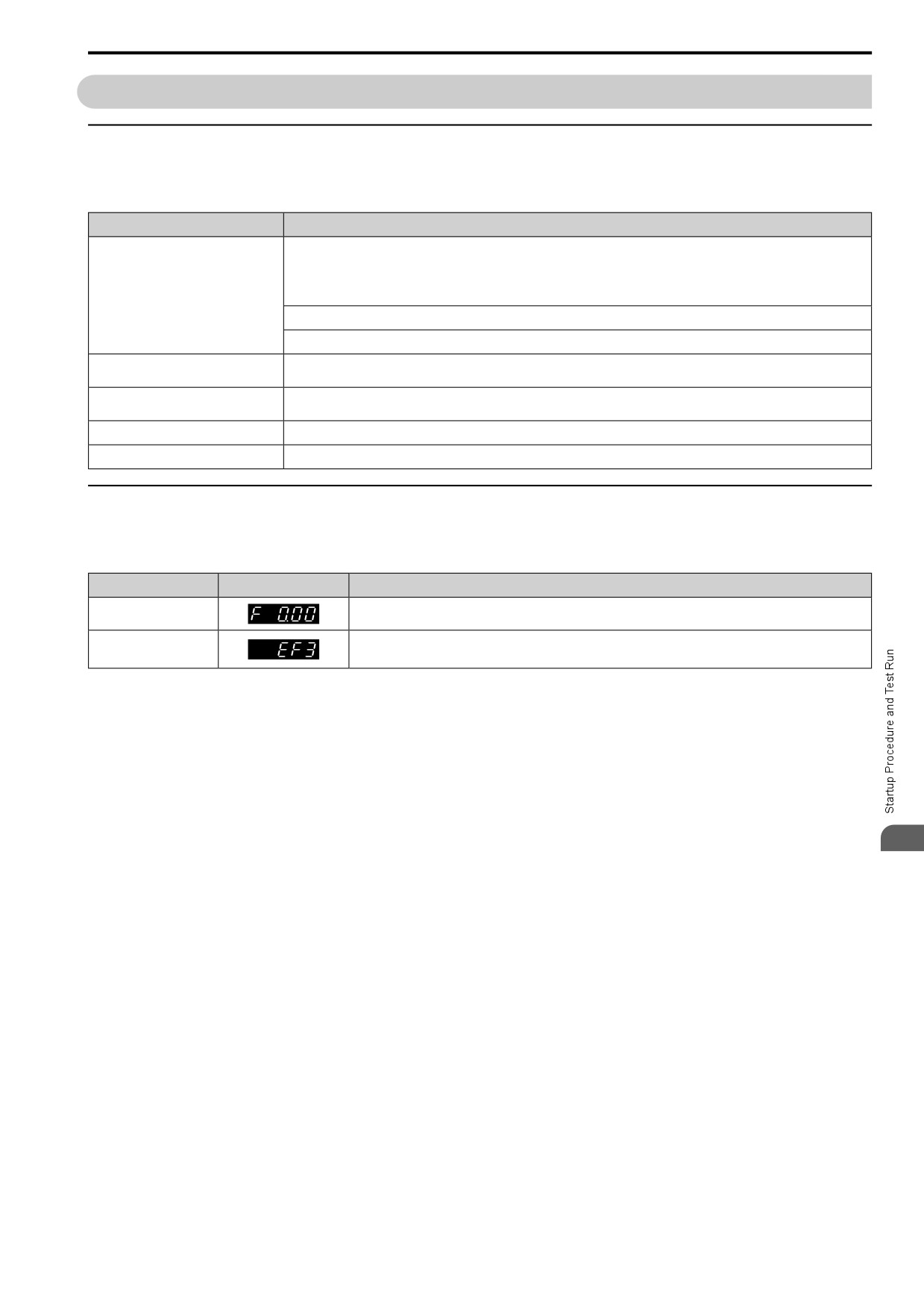
Table 4.5 Items to Check before You Energize the Drive
Items to Check
Description
The voltage of the input power supply must be:
Three-phase 200 V class: three-phase 200 Vac to 240 Vac 50/60 Hz, 270 Vdc to 340 Vdc
Single-phase 200 V class: single-phase 200 Vac to 240 Vac 50/60 Hz, 270 Vdc to 340 Vdc
Input Power Supply Voltage
Three-phase 400 V class: three-phase 380 Vac to 480 Vac 50/60 Hz, 513 Vdc to 679 Vdc
Correctly wire power supply input terminals R/L1, S/L2, and T/L3, or L and N.
Correctly ground the drive and motor.
Connection between Drive Output
Make sure that you connected drive output terminals U/T1, V/T2, and W/T3 in the correct sequence to align with motor terminals U,
Terminals and Motor Terminals
V, and W and tighten the screws to a correct tightening torque.
Make sure that you connected the drive control circuit terminals in the correct sequence to align with devices and switches and
Control Circuit Terminal Wiring
tighten the screws to a correct tightening torque.
Control Circuit Terminal Status
Turn OFF the inputs from all devices and switches connected to the drive control circuit terminals.
Connection between Machinery and Motor
Disengage all couplings and belts that connect the motor and machinery.
◆ Check after You Energize the Drive
Check the following items after you energize the drive. The keypad display is different depending on drive status.
Table 4.6 Display Status after You Energize the Drive
Status
Display
Description
The LED display shows the frequency reference.
During Usual Operation
When the Drive Detects a
The display is different for different faults. Refer to “213” to remove the cause of the fault.
Fault
The ALM LED will illuminate/blink.
4
117
4.7 Keypad Operation
4.7
Keypad Operation
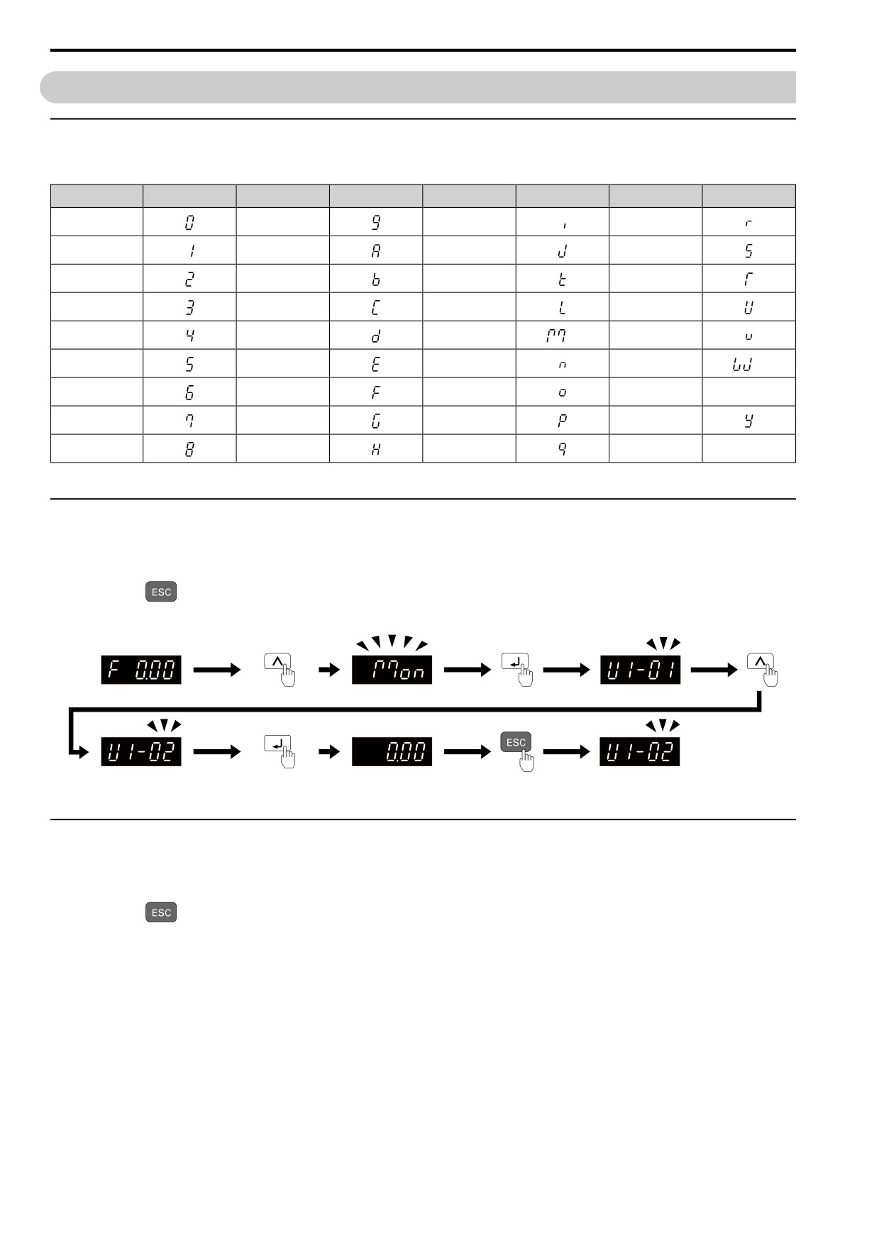
◆ Digital Character Mapping Table
The LED keypad shows the digital characters as follows.
Characters
LED Display
Characters
LED Display
Characters
LED Display
Characters
LED Display
0
9
I
R
1
A
J
S
2
B
K
T
3
C
L
U
4
D
M
*1
V
5
E
N
W
*1
6
F
O
X
No indication
7
G
P
Y
8
H
Q
Z
No indication
*1
Shown across two digits.
◆ Show the Monitor
Show the frequency reference screen in advance.
Note:
Push and hold
to go back to the frequency reference screen from any screen.
Use these steps to monitor parameter settings.
Figure 4.13 How to Monitor the Parameter Setting Values
◆ Check Modified Parameters
Show the frequency reference screen in advance.
Note:
Push and hold
to go back to the frequency reference screen from any screen.
Use Verify mode to view all parameters that are not at default settings. This is very useful when you replace a
drive. This lets you quickly access and re-edit changed parameters.
Note:
The drive will only display A1-02 [Control Method], A1-xx, A2-01 to A2-32 [MAN1 Param1 to MAN3 Param12], and E5-01 [PM Mot
Code Selection].
118
4.7 Keypad Operation
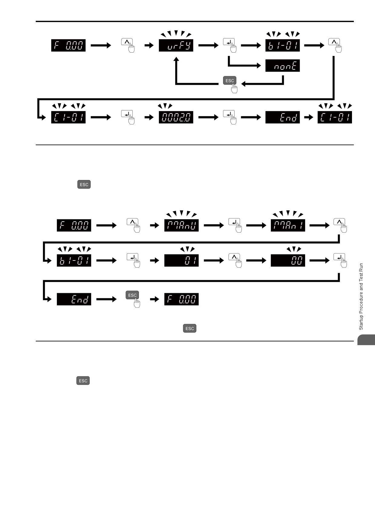
Figure 4.14 How to Examine the Changed Parameters
◆ Set and View Necessary Parameters
Show the frequency reference screen.
Note:
Press and hold
to return to frequency reference screen from any screen.
The Manual Setup mode shows the parameters and monitors set in A2-01 to A2-32 [MAN1 Param1 to MAN3
Param12]. This lets you quickly access and view and change these parameters and monitors.
Figure 4.15 View and Set the Necessary Parameters
Continue to change the parameters or press and hold
to go back to the frequency reference screen.
4
◆ Change Parameter Settings
Show the frequency reference screen in advance.
Note:
Push and hold
to go back to the frequency reference screen from any screen.
This example shows how to change C1-01 [Accel Time 1]. Set the parameter to the necessary value.
119
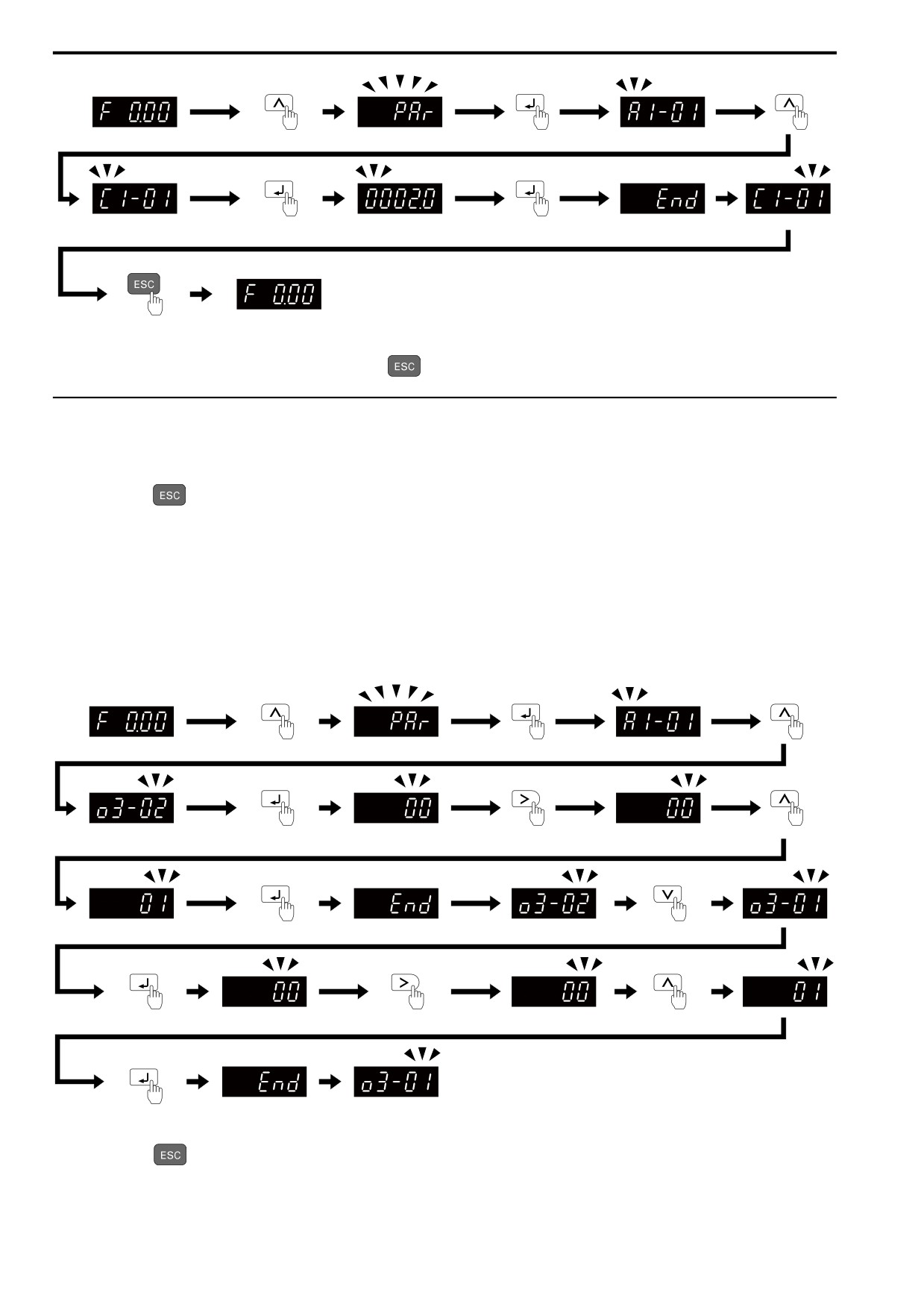
4.7 Keypad Operation
Figure 4.16 How to Change the Parameter Setting
Continue to change parameters or push and hold
to go back to the frequency reference screen.
◆ Save a Backup of Parameters
Show the frequency reference screen in advance.
Note:
Push and hold
to go back to the frequency reference screen from any screen.
Use these steps to save a backup of the drive parameters to the keypad.
Making backups of the parameter settings can save time when setting parameters after replacing a drive. If you set
up more than one drive, you can copy the parameter settings from a drive that completed a test run to the other
drives.
Note:
• Make sure that you stop the motor before you back up parameters.
• The drive does not accept Run commands while it is making a backup.
• Set o3-02 = 0 [COPY Allow Selection = Disabled] to protect the parameters saved in the keypad.
Figure 4.17 How to Save Backed-up Parameters
Push and hold
to go back to the frequency reference screen.
120