Q2V Driving Quality. Technical Manual (Item code: Q2V-Axxxx-xxx, 2020) - page 4
4.7 Keypad Operation
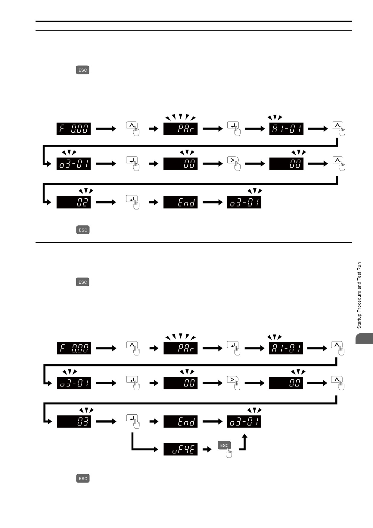
◆ Write Backed-up Parameters to the Drive
Show the frequency reference screen in advance.
Note:
Push and hold
to go back to the frequency reference screen from any screen.
Use these steps to write the parameters backed up in the keypad into a different drive.
Note:
• Make sure that you stop the drive before you restore the backed-up parameters.
• The drive does not accept Run commands while it is restoring parameters.
Figure 4.18 Writing backed up parameters
Push and hold
to go back to the frequency reference screen.
◆ Verify Keypad Parameters and Drive Parameters
Show the frequency reference screen in advance.
Note:
Push and hold
to go back to the frequency reference screen from any screen.
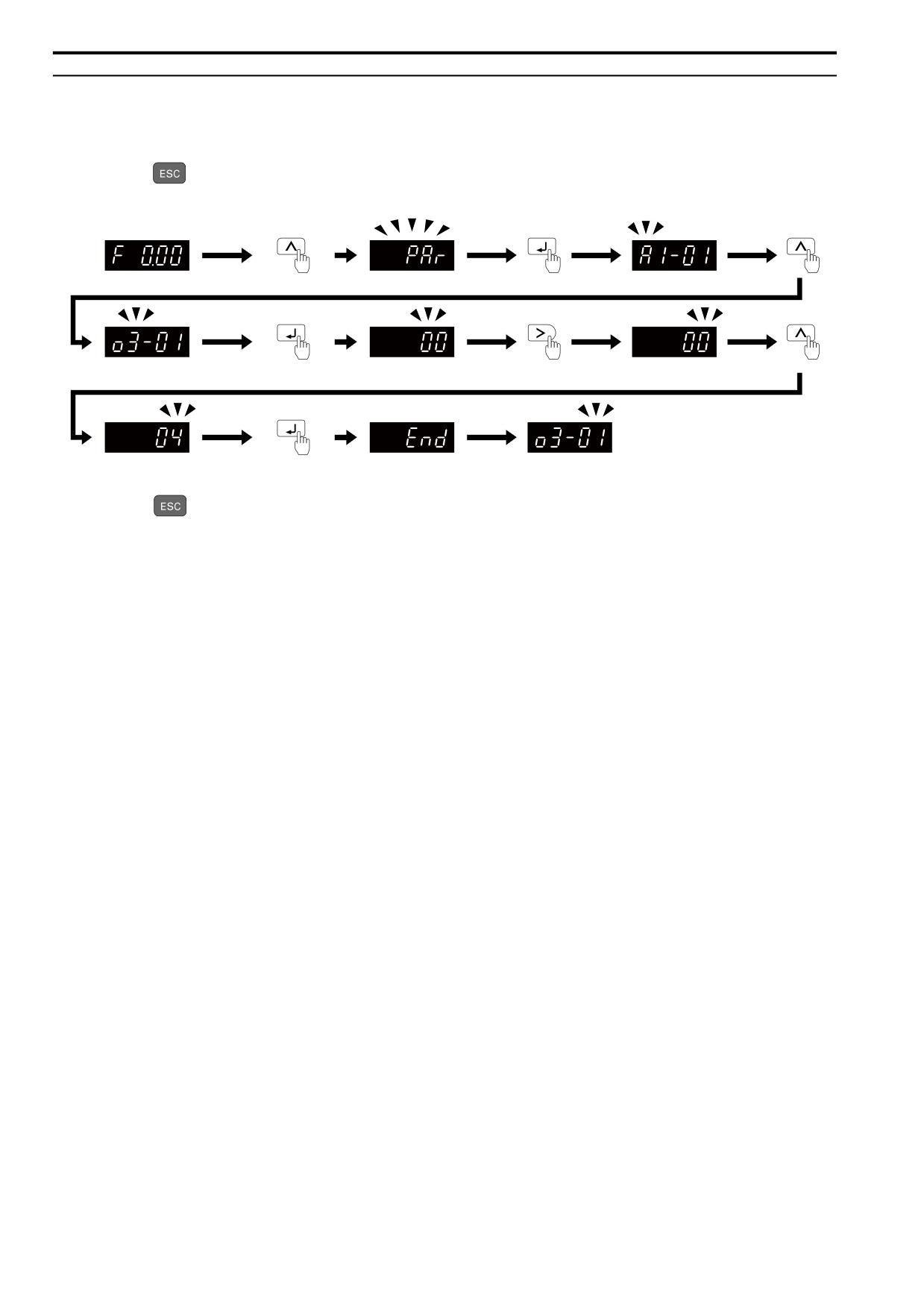
This procedure verifies that the parameter setting values that were backed up in the keypad agree with the
parameter setting values in the drive.
Note:
• Make sure that you stop the drive before you examine parameters.
• The drive does not accept Run commands while it is restoring parameters.
4
Figure 4.19 Verify Keypad Parameters and Drive Parameters
Push and hold
to go back to the frequency reference screen.
121
4.7 Keypad Operation
◆ Delete Parameters Backed Up to the Keypad
Show the frequency reference screen in advance.
Note:
Push and hold
to go back to the frequency reference screen from any screen.
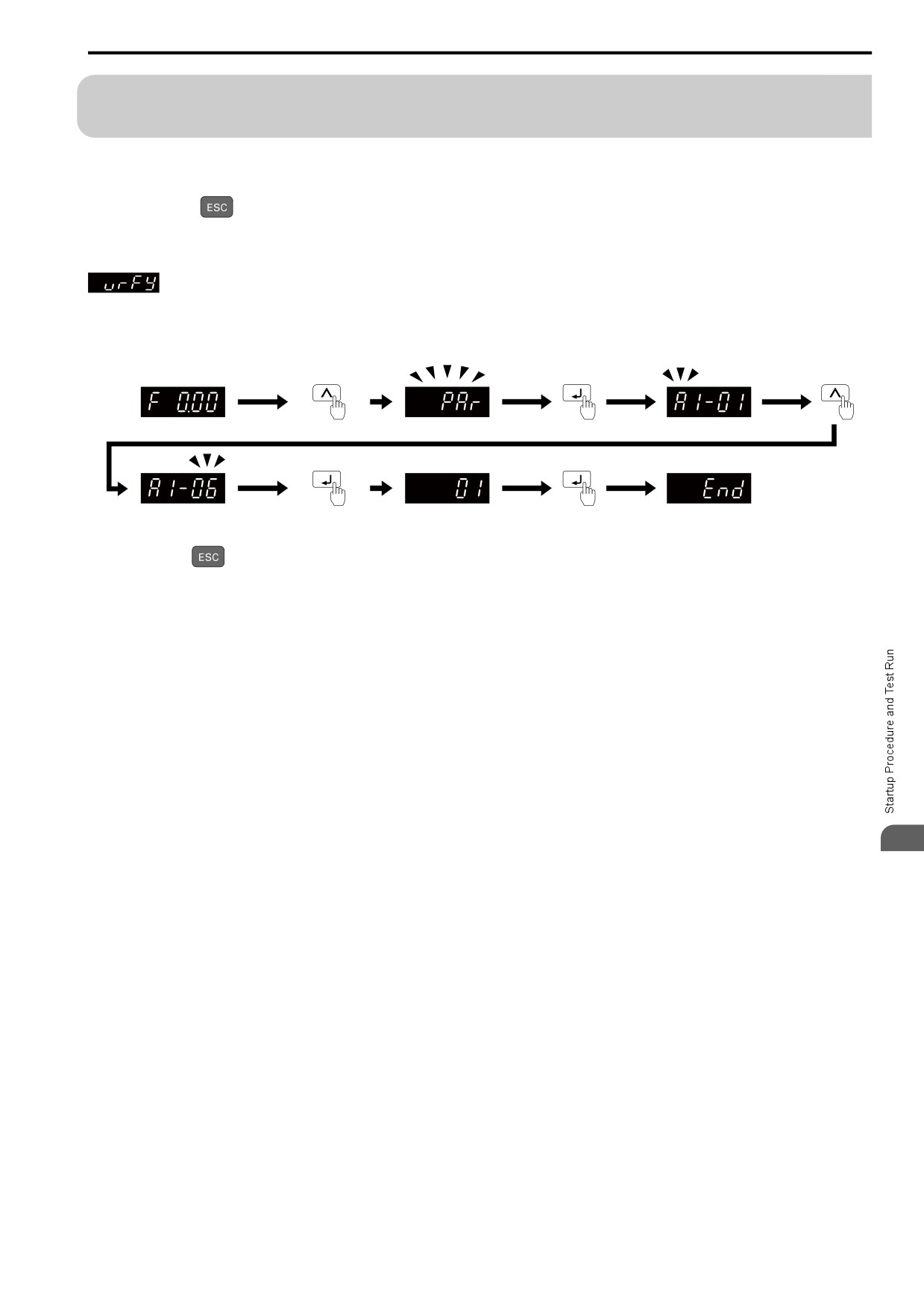
Use these steps to erase the parameters backed up in the keypad.
Figure 4.20 How to Erase the Backed-up Parameters
Push and hold
to go back to the frequency reference screen.
122
4.8 Automatic Parameter Settings Optimized for Specific Applications (Application Presets)
4.8
Automatic Parameter Settings Optimized for Specific
Applications (Application Presets)
Show the frequency reference screen.
Note:
Press and hold a
to return to frequency reference screen from any screen.
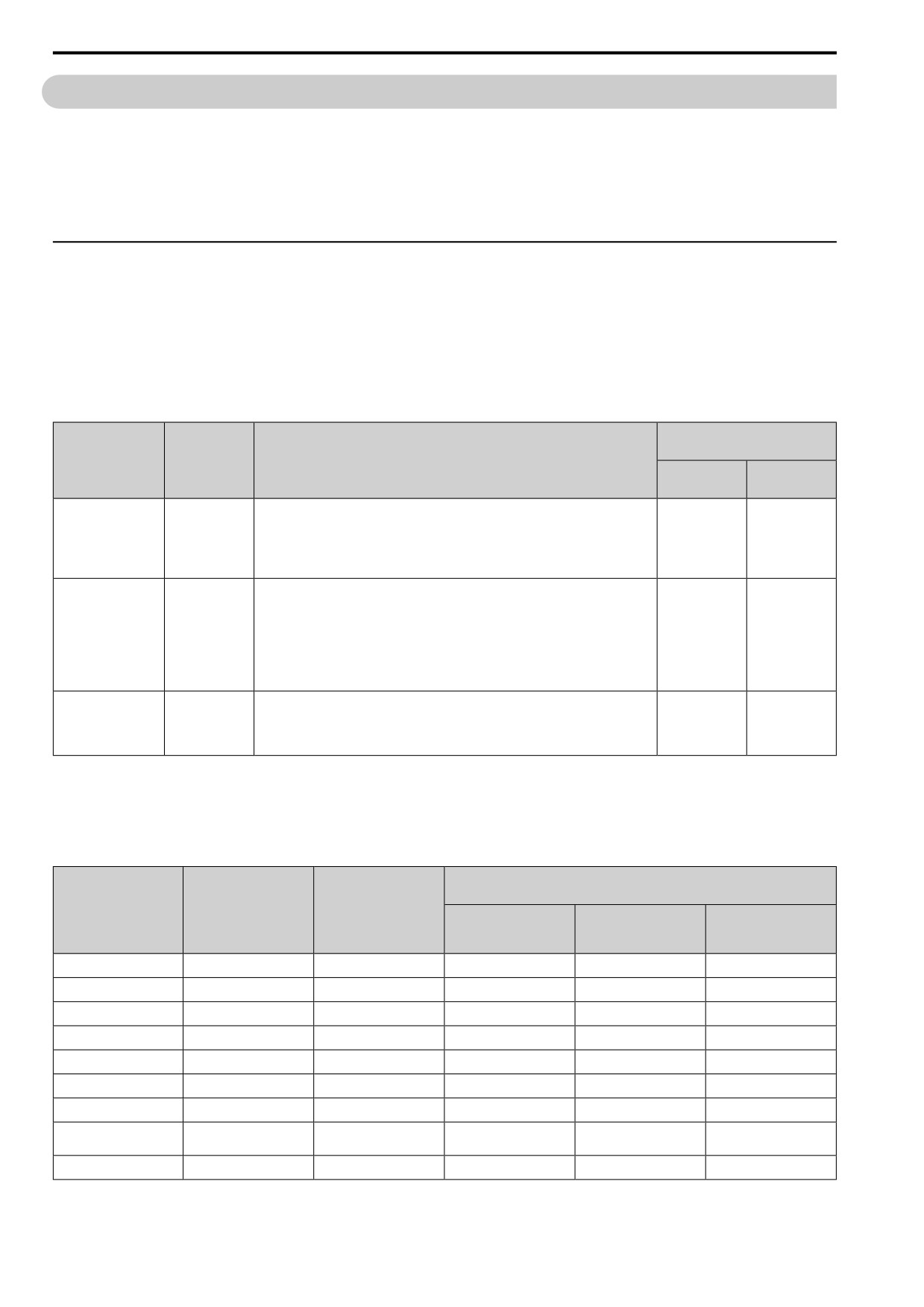
Use this procedure to set an application preset.
The drive has application presets to set the necessary parameters for different applications to their best values. Use
to find parameters that were changed automatically by the application preset function in A1-06.
Note:
Before you set A1-06, make sure that you set A1-03 = 2220, 3330 [Init Parameters = 2-Wire Initialization, 3-Wire Initialization] to
initialize parameters.
Figure 4.21 Automatic Parameter Settings
Press and hold
to go back to the frequency reference screen.
Note:
• Make sure that you do Auto-Tuning after you set A1-06 for a hoist application.
• It is not possible to change the A1-06 value. To set an application preset, first set A1-03 = 2220 to initialize parameters, then set this
parameter. If initializing all parameters will cause a problem, do not change the settings.
• When the drive changes to the A1-06 setting, it will also reset the parameters automatically registered to A2-17 to A2-32 [MAN2
Param7 to MAN3 Param12] when A2-33 = 1 [Manual Autoset Parameters = Auto Save].
4
123
4.9 Auto-Tuning
4.9
Auto-Tuning
Auto-Tuning uses motor characteristics to automatically set drive parameters for vector control. Think about the
type of motor, drive control method, and the motor installation environment and select the best Auto-Tuning
method.
WARNING! Crush Hazard. Rotational Auto-Tuning rotates the motor at 50% or more of the motor rated frequency. Make sure
that there are no issues related to safety in the area around the drive and motor. Increased motor frequency can cause serious
injury or death.
◆ Auto-Tuning for Induction Motors
This section gives information about Auto-Tuning for induction motors. Set motor parameters E1-xx and E2-xx
(or, for motor 2, E3-xx and E4-xx) for Auto-Tuning.
Note:
Do Stationary Auto-Tuning if you cannot do Rotational Auto-Tuning. There can be large differences between the measured results and
the motor characteristics when Auto-Tuning is complete. Examine the parameters for the measured motor characteristics after you do
Stationary Auto-Tuning.
Table 4.7 Auto-Tuning Mode Selection
Applicable Control Method
(A1-02 Setting)
Parameter
Method
Application Conditions and Benefits
Settings
V/f Control
OLVector
(0)
(2)
• When you can decouple the motor and load the motor can rotate freely while Auto-
Tuning.
Rotational Auto-
T1-01 = 0
• When operating motors that have fixed output characteristics.
x
x
Tuning
• When it is necessary to use motors that have high-precision control.
• When you cannot decouple the motor and load, but the motor load is less than 30%.
• When you cannot decouple the motor and load.
• When the motor load is more than 30%.
• When the information from the motor test report or motor nameplate is not available.
Stationary Auto-Tuning
With Stationary Auto-Tuning, the energized drive stays stopped for approximately 1
T1-01 = 1
-
x
1
minute. During this time, the drive automatically measures the necessary motor
parameters.
• When operating the motor with a less than 30% light load after Auto-Tuning.
Set T1-12 = 1 [Test Mode Selection = Yes] to do a test run after Auto-Tuning.
• After Auto-Tuning, the wiring distance between the drive and motor changed by 50 m
or more.
Stationary Line-Line
T1-01 = 2
x
x
Resistance
• When the wiring distance is 50 m or more in the V/f Control mode.
• When the motor output and drive capacity are different.
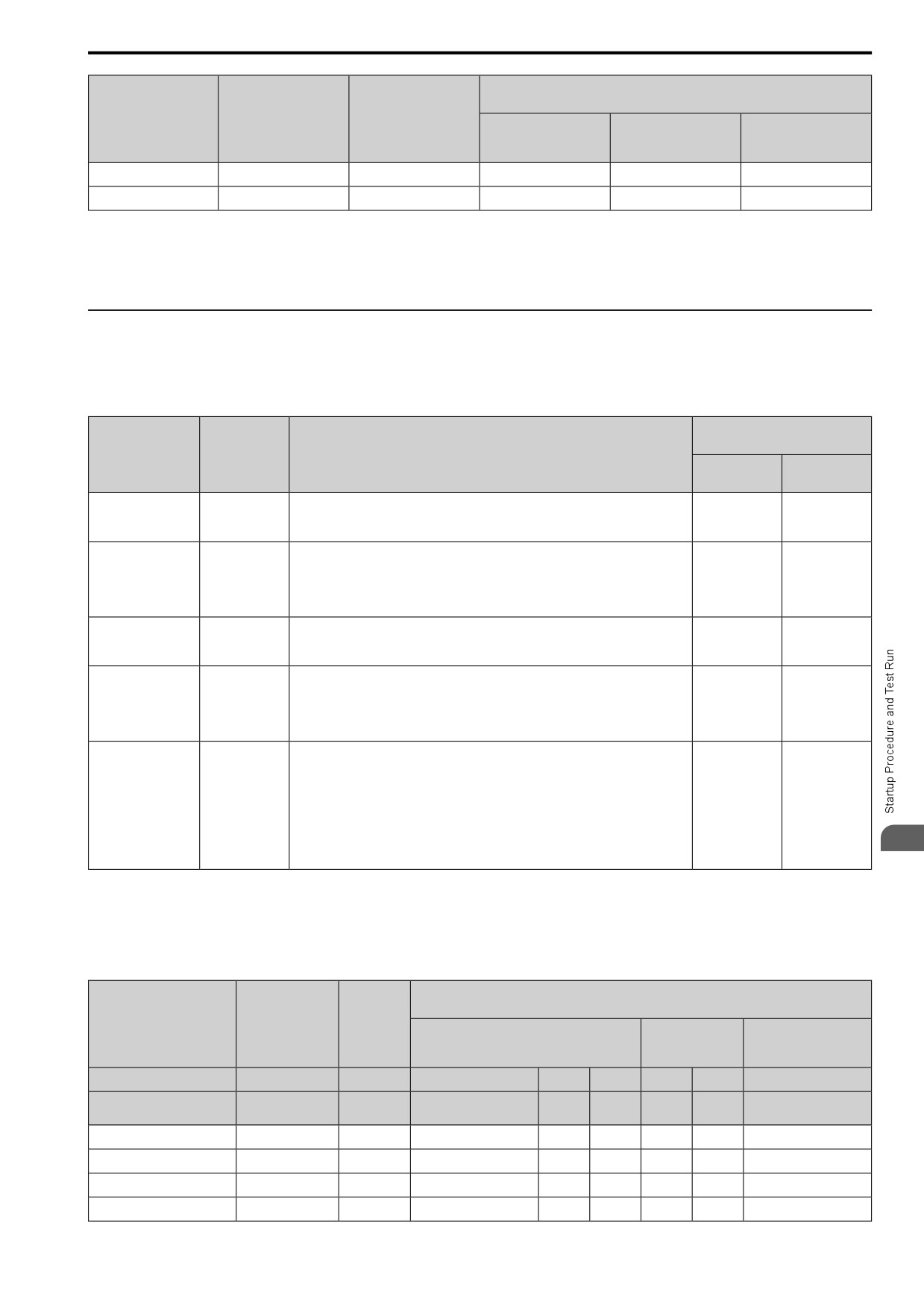
■ Input Data for Induction Motor Auto-Tuning
To do Auto-Tuning, input data for the items that have an "x" in the table below. Before starting Auto-Tuning,
prepare the motor test report or record the information on the motor nameplate as a reference.
Table 4.8 Input Data for Induction Motor Auto-Tuning
Auto-Tuning Mode
(T1-01 Setting)
Input Data
Parameter
Unit
Stationary Auto-Tuning
Stationary Line-Line
Rotational Auto-Tuning
1
Resistance
(0)
(1)
(2)
Motor Rated Power
T1-02
kW
x
x
x
Motor Rated Voltage
T1-03
V
x
x
-
Motor Rated Current
T1-04
A
x
x
x
Motor Base Frequency
T1-05
Hz
x
x
-
Motor Poles Number
T1-06
-
x
x
-
Motor Base Speed
T1-07
min-1
x
x
-
Motor NoLoad Current
T1-09
A
-
x
-
Motor Rated Slip
T1-10
Hz
-
x *1
-
Frequency
Motor Iron Loss
T1-11
W
x *2
-
-
124
4.9 Auto-Tuning
Auto-Tuning Mode
(T1-01 Setting)
Input Data
Parameter
Unit
Stationary Auto-Tuning
Stationary Line-Line
Rotational Auto-Tuning
1
Resistance
(0)
(1)
(2)
Test Mode Selection *3
T1-12
-
-
x *4
-
No-load Voltage
T1-13
V
x
x
-
*1
Shows 0 Hz as the default value. If you do not know the Motor Rated Slip Frequency, keep the setting at 0 Hz.
*2
Input this value when A1-02 = 0 [Control Method = V/f Control].
*3
If T1-12 = 1 [Test Mode Selection = Yes], when you run the motor in Drive Mode for the first time after Auto-Tuning, the drive will
automatically set E2-02 [Mot Rated Slip] and E2-03 [Mot No-Load Current].
*4
Input this value when T1-10 [Motor Rated Slip Frequency] = 0 Hz.
◆ Auto-Tuning for PM Motors
This section gives information about Auto-Tuning for PM motors. Auto-Tuning sets motor parameters E1-xx and
E5-xx.
Table 4.9 Auto-Tuning for PM Motors
Applicable Control Method
(A1-02 Setting)
Parameter
Mode
Application Conditions and Benefits
Settings
PM OLVector
PM AOLVector
(5)
(6)
• When the information from the motor test report or motor nameplate is available.
Manual Entry w/ Motor
T2-01 = 0
• Rotational/Stationary Auto-Tuning that energizes the motor is not done. Manually
x
x
Data Sheet
input the necessary motor parameters.
• When the information from the motor test report or motor nameplate is not available.
Note:
PM Stationary Auto-
T2-01 = 1
x
x
Tuning
With Stationary Auto-Tuning, the energized drive stays stopped for approximately 1
minute. During this time, the drive automatically measures the necessary motor
parameters.
PM Stationary Auto-
• After Auto-Tuning, the wiring distance between the drive and motor changed by 50 m
Tuning for Stator
T2-01 = 2
(164 ft) or more.
x
x
Resistance
• When the motor output and drive capacity are different.
• When the information from the motor test report or motor nameplate is not available.
• When you can decouple the motor and load and the motor can rotate freely while Auto-
PM Motor Code
T2-01 = 4
Tuning.
x
x
Selection
• The drive will automatically set the values measured during Auto-Tuning to the motor
parameters.
• Automatically sets the control parameters that are necessary to set n8-35 = 2
[InitRotorPos Selection = ] or n8-57 = 1 [High-Freq Injection = Enabled].
• Applicable to IPM motors only.
• Do Auto-Tuning with the motor connected to the drive.
High Frequency
T2-01 = 5
x
x
Injection
Note:
When you set n8-35 = 1 or n8-57 = 1, do High Frequency Injection Auto-Tuning. Set
the data on the motor nameplate to the drive before you do High Frequency Injection
4
Auto-Tuning. In High Frequency Injection Auto-Tuning, the drive energizes the
stopped motor and automatically adjusts the parameters.
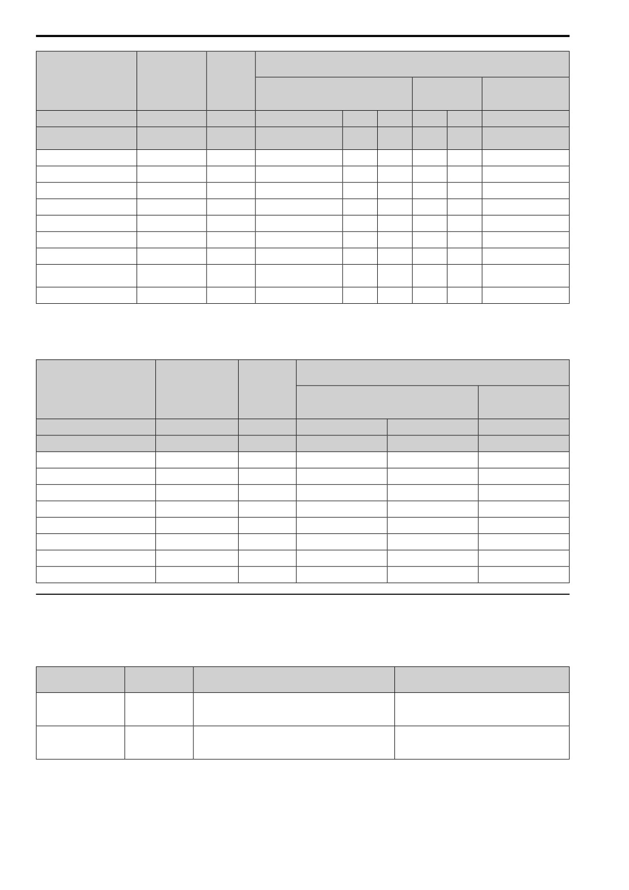
■ Input Data for PM Motor Auto-Tuning
To do Auto-Tuning, input data for these items that have an "x". Before starting Auto-Tuning, prepare the motor
test report or record the information on the motor nameplate as a reference.
Table 4.10 Input Data for PM Motor Auto-Tuning
Auto-Tuning Mode
(T2-01 Setting)
Input Data
Parameter
Unit
PM Static Full
PM Motor Parameter Settings
PM Static R Autotune
AutoTune
(0)
(2)
(1)
Control Method Selection
A1-02
-
5, 6
5
6
5
6
5, 6
Motor code of Yaskawa
PM Motor Code Selection
T2-02
-
FFFF *2
FFFF *2
-
-
-
motor *1
PM Motor Type
T2-03
-
-
-
-
x
x
-
PM Motor Rated Power
T2-04
kW
-
x
x
x
x
-
PM Motor Rated Voltage
T2-05
V
-
x
x
x
x
-
PM Motor Rated Current
T2-06
A
-
x
x
x
x
x
125
4.9 Auto-Tuning
Auto-Tuning Mode
(T2-01 Setting)
Input Data
Parameter
Unit
PM Static Full
PM Motor Parameter Settings
PM Static R Autotune
AutoTune
(0)
(2)
(1)
Control Method Selection
A1-02
-
5, 6
5
6
5
6
5, 6
Motor code of Yaskawa
PM Motor Code Selection
T2-02
-
FFFF *2
FFFF *2
-
-
-
motor *1
PM Motor Base Frequency
T2-07
Hz
-
x
-
x
-
-
Number of PM Motor Poles
T2-08
-
-
x
x
x
x
-
PM Motor Base Speed
T2-09
min-1
-
-
x
-
x
-
PM Motor Stator Resistance
T2-10
Ω
x
x
x
-
-
-
PM Motor d-Axis Inductance
T2-11
mH
x
x
x
-
-
-
PM Motor q-Axis Inductance
T2-12
mH
x
x
x
-
-
-
Back-EMF Units Selection
T2-13
-
x
x
x
-
-
-
Back-EMF Voltage Constant
T2-14
*3
x
x
x
-
-
-
(Ke)
Pull-In Current Level
T2-15
%
-
-
-
x
x
-
*1
Set the motor code for a Yaskawa PM motor.
*2
Set the motor code to FFFF for a PM motor from a different manufacturer.
*3
Changes when the value set in T2-13 changes.
Table 4.11 Input Data for PM Motor Auto-Tuning
Auto-Tuning Mode
(T2-01 Setting)
Input Data
Parameter
Unit
High Frequency
PM Rotary Autotune
Injection
(4)
(5)
Control Method Selection
A1-02
-
5
6
5, 6
PM Motor Code Selection
T2-02
-
-
-
-
PM Motor Type
T2-03
-
x
x
-
PM Motor Rated Power
T2-04
kW
x
x
-
PM Motor Rated Voltage
T2-05
V
x
x
-
PM Motor Rated Current
T2-06
A
x
x
-
PM Motor Base Frequency
T2-07
Hz
x
-
-
Number of PM Motor Poles
T2-08
-
x
x
-
PM Motor Base Speed
T2-09
min-1
-
x
-
Pull-In Current Level
T2-15
%
x
x
-
◆ Auto-Tuning in EZ Open Loop Vector Control Method
This section gives information about the Auto-Tuning mode for EZ Open Loop Vector Control. Auto-Tuning will
set the E9-xx parameters.
Table 4.12 EZ Tuning Mode Selection
Parameter
Applicable Control Method
Mode
Application Conditions and Benefits
Settings
(A1-02 Setting)
• Applicable when driving an induction motor or a PM motor
EZ Vector
Motor Parameter Setting
T4-01 = 0
• Suitable for derating torque applications, for example fans and
(8)
pumps.
• After Auto-Tuning, the wiring distance between the drive and
EZ Vector
Line-to-Line Resistance
T4-01 = 1
motor changed by 50 m or more.
(8)
• When the motor output and drive capacity are different.
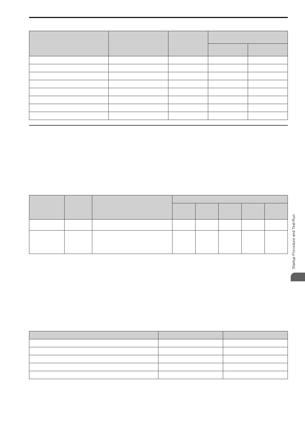
■ Auto-Tuning Input Data in EZ Open Loop Vector Control Method
To do Auto-Tuning, input data for the items that have an "x". Before starting Auto-Tuning, prepare the motor test
report or record the information on the motor nameplate as a reference.
126
4.9 Auto-Tuning
Table 4.13 Auto-Tuning Input Data in EZ Open Loop Vector Control Method
Auto-Tuning Mode
(T4-01 Setting)
Input Data
Parameter
Unit
Motor Constant
Static R Autotune
(0)
(1)
Motor Type Selection
T4-02
-
x
-
Motor Max Revolutions
T4-03
min-1
x
-
Motor Rated Revolutions
T4-04
min-1
x
-
Motor Rated Frequency
T4-05
Hz
x
-
Motor Rated Voltage
T4-06
V
x
-
PM Motor Rated Current (FLA)
T4-07
A
x
x
PM Motor Rated Power (kW)
T4-08
kW
x
-
Number of Motor Poles
T4-09
-
x
-
◆ ASR and Inertia Tuning
To increase drive responsiveness and prevent hunting, use Auto-Tuning to automatically adjust the control-related
parameters. These types of Auto-Tuning are available for the control system:
• Deceleration Rate Tuning
• KEB Tuning
Note:
If you do Control Tuning, you cannot set H1-xx = 61 [Motor 2 Select]. Do not do Control Tuning for applications that switch between
motor 1 and motor 2.
Table 4.14 Control Loop Tuning Selection
Applicable Control Methods (A1-02 Settings)
Parameter
Mode
Application Conditions and Benefits
PM
PM
Settings
V/f Control
OLVector
EZ Vector
OLVector
AOLVector
(0)
(2)
(8)
(5)
(6)
Deceleration Rate
To automatically adjust the deceleration rate to
T3-00 = 2
x
x
x
x
x
Tuning
prevent an ov [Overvoltage] fault.
• To automatically adjust parameter settings to
prevent an ov [Overvoltage] fault with the KEB
KEB Tuning
T3-00 = 3
Ride-Thru function.
x
x
x
x
x
• When L3-11 = 1 [Overvolt Supression Select =
Enabled].
■ Deceleration Rate Tuning
Deceleration Rate Tuning automatically sets the deceleration rate to prevent an ov [Overvoltage] fault during
4
motor deceleration. Set C1-11 [Accel/Decel Time Switchover Freq] first to automatically set parameters C1-02
[Decel Time 1] (high speed range) and C1-08 [Decel Time 4] (low speed range).
■ KEB Tuning
KEB Tuning automatically sets parameters used for the KEB Ride-Thru function and for the overvoltage
suppression function.
Control Tuning automatically sets these parameters in to the best values.
Table 4.15 Parameters set in Control Tuning
Parameters Automatically Set
Deceleration Rate Tuning
KEB Tuning
C1-02 [Decel Time 1]
x
-
C1-08 [Decel Time 4]
x *1
-
C1-09 [Fast Stop Time]
-
x *2
L2-06 [KEB Decel Time]
-
x *3
L3-25 [Load Inertia Ratio]
-
x
*1
The drive automatically sets C1-08 [Decel Time 4] only when C1-11 [Ac/Dec Switch Frequency] ≠ 0.
*2
When L2-29 = 1 [KEB Method = Single KEB1 Ride-Thru], the drive will automatically adjust C1-09 [Fast Stop Time] and will not
adjust L2-06 [KEB Decel Time]. If you must not change the Fast Stop time, do not do KEB Tuning.
127
4.9 Auto-Tuning
*3
When L2-29 = 2, 3, or 4 [KEB Method = Single KEB2 Ride-Thru, System KEB1 Ride-Thru, or System KEB2 Ride-Thru], the drive
will automatically adjust L2-06 [KEB Decel Time].
◆ Precautions before Auto-Tuning
Examine the topics in this section before you start Auto-Tuning.
■ Prepare for Basic Auto-Tuning
• You must input data from the motor nameplate or motor test report to do Auto-Tuning. Make sure that this data
is available before you do Auto-Tuning.
• For best performance, make sure that the drive input supply voltage is equal to or more than the motor rated
voltage.
Note:
Better performance is possible when you use a motor with a rated voltage that is less than the input supply voltage (by 20 V for 200 V
class models or by 40 V for 400 V class models). This is very important when you operate the motor at more than 90% of base speed,
where high torque precision is necessary. If the input power supply is equal to the motor rated voltage, the drive output voltage will not
be sufficient and performance will decrease.
• Push
on the keypad to cancel Auto-Tuning.
• If a Safe Disable input signal is input to the drive during Auto-Tuning, Auto-Tuning measurements will not
complete successfully. If this occurs, cancel the Auto-Tuning, then do it again.
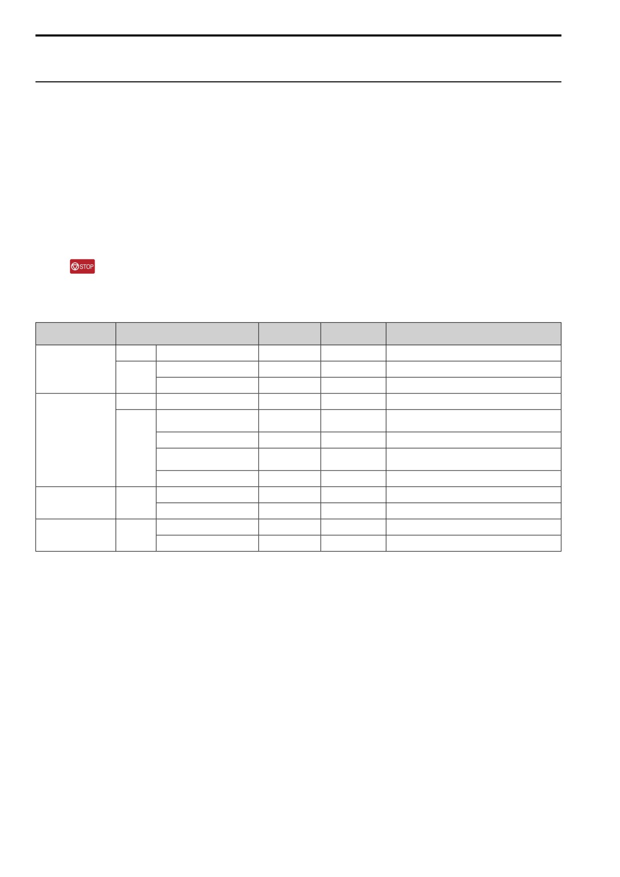
Table 4.16 Status of Input/Output Terminals during Auto-Tuning
Multi-Function
Auto-Tuning Type
Mode
Parameter
Multi-Function Output *1
Input
Rotational
Rotational Auto-Tuning
T1-01 = 0
Disabled
Functions the same as during usual operation.
Induction Motor Auto-
Stationary Auto-Tuning 1
T1-01 = 1
Disabled
Keeps the status at the start of Auto-Tuning.
Tuning
Stationary
Line-to-Line Resistance
T1-01 = 2
Disabled
Keeps the status at the start of Auto-Tuning.
Rotational
PM Motor Code Selection
T2-01 = 4
Disabled
Functions the same as during usual operation.
Manual Entry w/ Motor Data
T2-01 = 0
Disabled
Disabled
Sheet
PM Motor Auto-Tuning
PM Stationary Auto-Tuning
T2-01 = 1
Disabled
Keeps the status at the start of Auto-Tuning.
Stationary
PM Stationary Auto-Tuning for
T2-01 = 2
Disabled
Keeps the status at the start of Auto-Tuning.
Stator Resistance
High Frequency Injection
T2-01 = 5
Disabled
Keeps the status at the start of Auto-Tuning.
Motor Parameter Setting
T4-01 = 0
Disabled
Disabled
EZ Tuning
Stationary
Line-to-Line Resistance
T4-01 = 1
Disabled
Keeps the status at the start of Auto-Tuning.
Deceleration Rate Tuning
T3-00 = 2
Disabled
Functions the same as during usual operation.
ASR and Inertia Tuning
Rotational
KEB Tuning
T3-00 = 3
Disabled
Functions the same as during usual operation.
*1
When you set a terminal to H2-xx = 3 [MFDO Function Selection = Fault], it will function the same as during usual operation.
WARNING! Crush Hazard. Wire a sequence that will not let a multi-function output terminal open the holding brake during
Stationary Auto-Tuning. If the holding brake is open during Stationary Auto-Tuning, it can cause serious injury or death.
WARNING! Sudden Movement Hazard.. Before you do Rotational Auto-Tuning, disconnect the load from the motor. The load
can move suddenly and cause serious injury or death.
WARNING! Crush Hazard. Rotational Auto-Tuning rotates the motor at 50% or more of the motor rated frequency. Make sure
that there are no issues related to safety in the area around the drive and motor. Increased motor frequency can cause serious
injury or death.
WARNING! Electrical Shock Hazard. During Auto-Tuning, the motor will receive high voltage when the motor is stopped. Do not
touch the motor until Auto-Tuning is complete. If you touch a motor that is energized, it can cause serious injury or death.
■ Precautions before Rotational Auto-Tuning
WARNING! Electrical Shock Hazard. During Auto-Tuning, the motor will receive high voltage when the motor is stopped. Do not
touch the motor until Auto-Tuning is complete. If you touch a motor that is energized, it can cause serious injury or death.
• Uncouple the drive from the motor before Rotational Auto-Tuning to prevent drive malfunction. If you do
Rotational Auto-Tuning with the motor connected to a load that is more than 30% of the motor duty rating, the
drive will not correctly calculate the motor parameters and the motor can operate incorrectly.
• When the load is 30% or less of the motor duty rating, you can do Auto-Tuning with the motor connected to a
load.
• Make sure that the motor magnetic brake is released.
• Make sure that external force from the machine will not cause the motor to rotate.
128
4.9 Auto-Tuning
■ Precautions before Stationary Auto-Tuning
• Make sure that the motor magnetic brake is not open.
• Make sure that external force from the machine will not cause the motor to rotate.
WARNING! Electrical Shock Hazard. During Auto-Tuning, the motor will receive high voltage when the motor is stopped. Do not
touch the motor until Auto-Tuning is complete. If you touch a motor that is energized, it can cause serious injury or death.
■ Automatically Set E2-02 [Mot Rated Slip] and E2-03 [Mot No-Load Current]
If T1-12 = 1 [Test Mode Selection = Yes] when selecting Stationary Auto-Tuning, the drive will automatically set
motor parameters E2-02 [Mot Rated Slip] and E2-03 [Mot No-Load Current] after Auto-Tuning is complete when
you use the motor for the first time in Drive Mode.
After Stationary Auto-Tuning is complete, use this procedure to do the operation in test mode:
1. Check the E2-02 and E2-03 values on the “Modified Parameters/Fault Log” screen or the “Parameters” screen.
2. Operate the motor in Drive Mode with these conditions:
• Make sure that you connect all wiring between the drive and motor
• Make sure that a mechanical brake on the motor shaft is not locked
• The maximum motor load must be 30% of the rated load.
• Keep a constant speed of 30% of E1-06 [Base Frequency] (default value = maximum frequency) or more
for 1 second or longer.
3. After the motor stops, examine the values of E2-02 and E2-03 again in the Verify Menu or Parameter Setting
Mode.
4. Make sure that the input data is correct.
When the settings in E2-02 and E2-03 are different than in step 1, the drive set the values automatically.
■ Precautions before Stationary Auto-Tuning for Line-to-Line Resistance and Stator
Resistance Auto-Tuning
In V/f control, when the motor cable is 50 meters (164 feet) or longer, do Stationary Auto-Tuning for Line-to-Line
Resistance.
WARNING! Electrical Shock Hazard. During Auto-Tuning, the motor will receive high voltage when the motor is stopped. Do not
touch the motor until Auto-Tuning is complete. If you touch a motor that is energized, it can cause serious injury or death.
■ Precautions before Using Deceleration Rate Tuning and KEB Tuning
Before Deceleration Rate Tuning or KEB Tuning, check these items:
• Do not do Deceleration Rate Tuning if you use a braking resistor unit or a regenerative converter.
• Do Deceleration Rate Tuning and KEB Tuning with the load attached to the motor.
• Do not do Deceleration Rate Tuning or KEB Tuning for these applications:
In Deceleration Rate Tuning and KEB Tuning, the drive will automatically rotate the motor forward and
accelerate and decelerate the motor again and again.
4
- On a machine that does not let the motor rotate forward
- In applications with a small range of operation (trolleys and other such applications that can only move
linearly)
- In elevator applications
- Applications where sudden acceleration and sudden deceleration are not applicable.
• To do KEB Tuning with the external main circuit capacitors connected to the drive, set L3-26 [DC Bus
Capacitors Extension] then do KEB Tuning.
• Do not do KEB Tuning or Deceleration Rate Tuning if the drive is set to use H1-xx = 61 [MFDI Function
Select = Motor 2 Select]. Failure to obey can cause an ov [Overvoltage] fault.
129
4.10 Test Run
4.10
Test Run
After you set the basic parameters and do Auto-Tuning, do a test run.
WARNING! Crush Hazard. Test the system to make sure that the drive operates safely after you wire the drive and set
parameters. If you do not test the system, it can cause damage to equipment or serious injury or death.
◆ No-Load Test Run
Before connecting the motor to the machine, make sure that you check the operation status of the motor.
■ Precautions before Operation
Before rotating the motor, check these items:
• Check for safety issues near the drive, motor, and machine.
• Make sure that all emergency stop circuits and machine safety mechanisms are operating correctly.
■ Items to Check before Operation
Check these items before operation:
• Is the motor rotating in the forward direction?
• Is the motor rotating smoothly (no unusual sounds or unusual vibrations)?
• Does the motor accelerate/decelerate smoothly?
◆ Do a No-Load Test Run
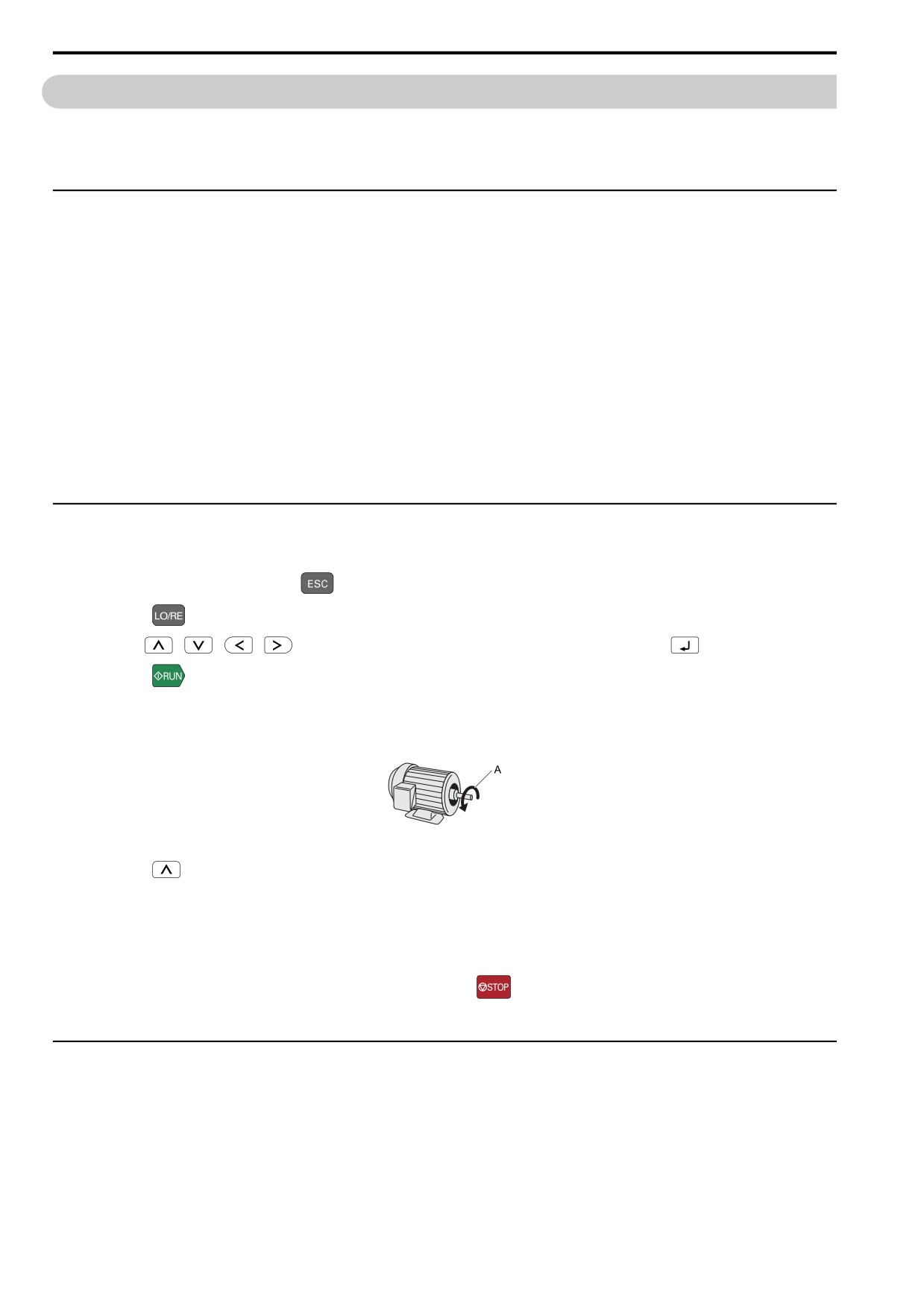
Do these steps for a no-load test run:
1. Energize the drive, or push
to show the frequency reference screen.
2. Push
to illuminate the LOCAL/REMOTE LED.
3. Use
/
/
/
to set d1-01 = 6.00 [Reference 1 = 6.00 Hz], then push
4. Push
The RUN indicator illuminates, and the motor runs at 6.00 Hz in the forward direction.
5. Make sure that the motor is rotating in the correct direction and that the drive does not show a fault.
If the drive detects a fault, remove the cause.
A - Forward Rotation of Motor (Counter Clockwise Direction as Seen from Load Shaft)
6. Push
to increase the frequency reference value.
Change the setting value in increments of 10 Hz if necessary and examine the response.
Ex.: 6 Hz → 20 Hz → 30 Hz → 40 Hz → 50 Hz → 60 Hz
7. Each time you increase the setting value, use U1-03 [Output Current] to check the drive output current.
When the output current of the drive is not more than the motor rated current, the status is correct.
8. Make sure that the motor rotates correctly, then push
The RUN LED flashes and goes off when the motor stops completely.
◆ Actual-Load Test Run
Test the operation without a load, then connect the motor and machine to do a test run.
■ Precautions before Operation
Before rotating the motor, check these items:
• Check for safety issues near the drive, motor, and machine.
• Make sure that all emergency stop circuits and machine safety mechanisms are operating correctly.
130
4.10 Test Run
• Make sure that the motor is fully stopped.
• Connect the motor with the machine.
Make sure that there are no loose installation screws and that the motor load shafts and machine junctions are
correctly secured.
• Keep the keypad near you to push
immediately if there is unusual or incorrect operation.
■ Items to Check before Operation
• Make sure that the direction of the machine operation is correct (The motor must rotate in the correct direction).
• Make sure that the motor accelerates and decelerates smoothly.
◆ Do an Actual-Load Test Run
Before a test run, make sure that U1-03 [Output Current] is not too high.
Connect the motor and machine, then do the test run with the same procedure that you used for the no-load test
run.
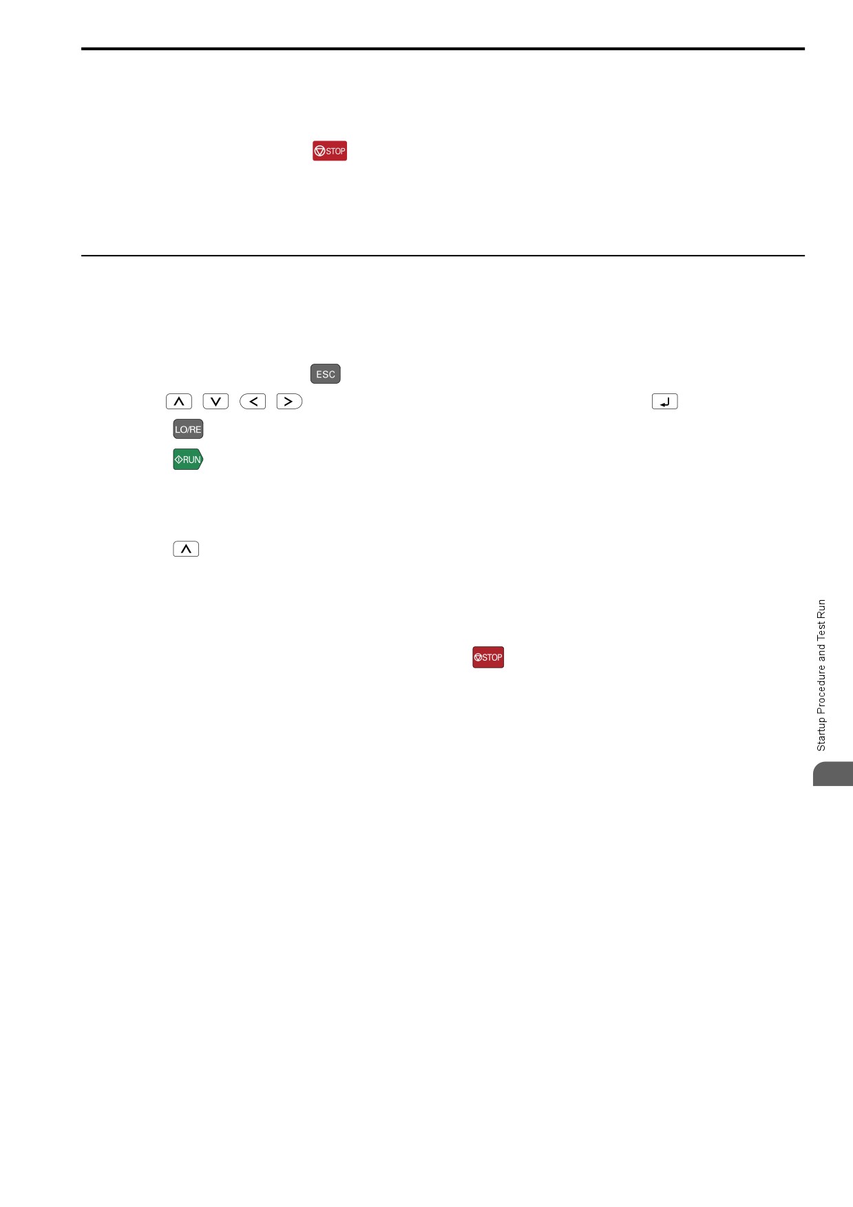
1. Energize the drive, or push
to show the frequency reference screen.
2. Use
/
/
/
to set d1-01 = 6.00 [Reference 1 = 6.00 Hz], then push
3. Push
to illuminate the LOCAL/REMOTE LED.
4. Push
The RUN indicator illuminates, and the motor runs at 6.00 Hz in the forward direction.
5. Make sure that the motor is rotating in the correct direction and that the drive does not show a fault.
If the drive detects a fault, remove the cause.
6. Push
to increase the frequency reference value.
Change the setting value in increments of 10 Hz if necessary and examine the response.
Ex.: 6 Hz → 20 Hz → 30 Hz → 40 Hz → 50 Hz → 60 Hz
7. Each time you increase the setting value, use U1-03 [Output Current] to check the drive output current.
When the output current of the drive is not more than the motor rated current, the status is correct.
8. Make sure that the motor rotates correctly, then push
The RUN LED flashes and goes off when the motor stops completely.
9. Change the frequency reference and direction of motor rotation, and make sure that there are no unusual
sounds or vibrations.
10. If the control function causes hunting or oscillation errors, adjust the settings to stop the errors.
4
131
4.11 Fine Tuning during Test Runs (Adjust the Control Function)
4.11
Fine Tuning during Test Runs (Adjust the Control
Function)
This section gives information about the adjustment procedures to stop hunting or oscillation errors caused by the
control function during a test run. Adjust the applicable parameters as specified by your control method and drive
status.
Note:
This section only lists frequently adjusted parameters. If you must adjust parameters that have a higher degree of precision, contact the
manufacturer.
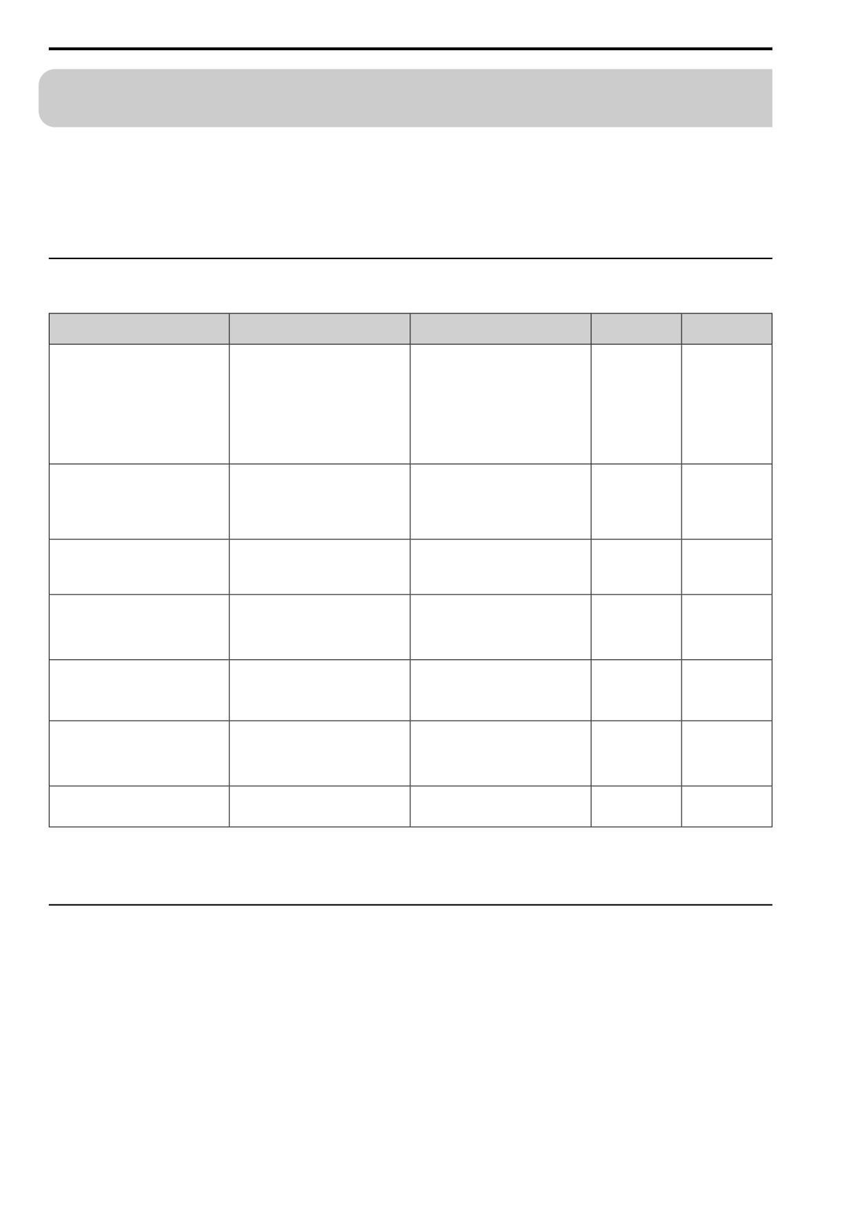
◆ V/f Control
Table
4.17 Parameters for Fine Tuning the Drive (A1-02 = 0 [V/f Control])
Issue
Parameter Number
Possible Solutions
Default
Recommended
Setting
• If torque is not sufficient with heavy
loads, decrease the setting value.
• If hunting or oscillation occur with light
loads, increase the setting value.
Hunting or oscillation at mid-range speeds
n1-02 [HuntPrev Gain Setting]
• If hunting occurs with a low-inductance
1.00
0.10
- 2.00
(10 Hz to 40 Hz)
motor, for example a motor with a
larger frame size or a high-frequency
motor, lower the setting value. Set n1-
01 = 1 [HuntPrev Selection =
Enabled].
• If the volume of the motor excitation
• The volume of the motor excitation
sound is too high, increase the carrier
sound is too high.
frequency.
1 to upper limit
• Hunting or oscillation at low speeds (10
C6-02 [Carrier Frequency Selection]
1
(2 kHz) *1
• If hunting or oscillation occur at low or
value
Hz or lower), or at mid-range speeds
mid-range speeds, decrease the carrier
(10 Hz to 40 Hz)
frequency.
• If torque or speed response are slow,
• Unsatisfactory motor torque and speed
decrease the setting value.
response
C4-02 [Trq Comp Delay Time]
200 ms *2
100 ms to 1000 ms
• If hunting or oscillation occur, increase
• Hunting or oscillation
the setting value.
• If torque at low speeds (10 Hz or lower)
• Torque at low speeds (10 Hz or lower)
is not sufficient, increase the setting
is not sufficient.
C4-01 [Trq Comp Gain]
value.
1.00
0.50
- 1.50
• Hunting or oscillation
• If hunting or oscillation occur with light
loads, decrease the setting value.
• If you use the drive with an IE3 high
Decrease the setting value in these
efficiency motor, the current that is
conditions:
more than the motor rated current will
C4-01 [Trq Comp Gain]
1.00
0.00
- 1.00
• Drive trips at overload.
flow and trip at overload. Hunting or
oscillation.
• Hunting or oscillation.
• If torque at low speeds (10 Hz or lower)
• Torque at low speeds (10 Hz or lower)
is not sufficient, increase the setting
• E1-08 [Mid A Voltage]
• E1-08: 16.0 V *3
Default setting +/- 5
is not sufficient.
value.
• E1-10 [Min Output Voltage]
• E1-10: 12.0 V *3
V *4
• Large initial vibration at start up.
• If there is large initial vibration at start
up, decrease the setting value
Set E2-01 [Mot Rated Current (FLA)], E2-
0.0
(no slip
Speed precision is unsatisfactory.
C3-01 [Slip Comp Gain]
02 [Mot Rated Slip], and E2-03 [Mot No-
0.5
- 1.5
compensation)
Load Current], then adjust C3-01.
*1
The default setting changes when the settings for C6-01 [ND/HD Duty Selection] and o2-04 [Drive KVA Selection] change.
*2
The default setting changes when the settings for A1-02 [Control Method] and o2-04 change.
*3
The default setting changes when the settings for A1-02 and E1-03 [V/f Pattern Selection] change.
*4
Recommended settings are for 200 V class drives. Multiply the voltage by 2 for 400 V class drives.
◆ Open Loop Vector Control Method
In Open Loop Vector Control, keep C4-01 [Trq Comp Gain] at its default setting (1.00).
If you cannot get speed precision during regeneration in Open Loop Vector Control, set C3-04 = 1 [Slip
Comp@Regen = Enable>6 Hz].
132
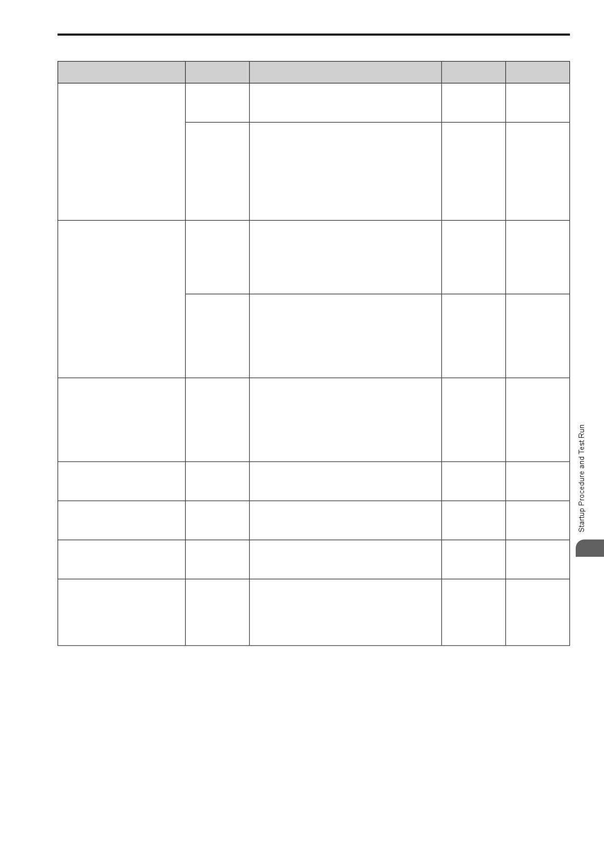
4.11 Fine Tuning during Test Runs (Adjust the Control Function)
Table 4.18 Parameters for Fine Tuning the Drive (A1-02 = 2 [OLVector])
Issue
Parameter
Possible Solutions
Default
Recommended
Number
Setting
•
To increase the speed of torque or speed response, decrease
the setting value in increments of 0.05.
n2-01 [AFR Gain]
1.00
0.50
- 2.00
•
If hunting or oscillation occur, decrease the setting value in
increments of 0.05.
•
To increase the speed of torque or speed response, decrease
the setting value in increments of 10 ms and examine the
• Unsatisfactory motor torque and speed
response.
response
•
If hunting or oscillation occur or if the load inertia is too
• Hunting or oscillation at mid-range
much, increase the setting value in increments of 50 ms and
speeds (10 Hz to 40 Hz)
examine the response.
n2-02 [AFR Time 1]
50 ms
50 ms to 2000 ms
Note:
Make sure that this parameter setting is: n2-02 ≤ n2-03 [AFR
Time 2] holds true.
When you adjust n2-02, you must also increase the C4-02
[Trq Comp Delay Time] value by the same ratio.
•
If ov occurs, increase the setting value in increments of 50 ms
and examine the response.
•
If the response is not sufficient, decrease the setting value in
increments of 10 ms and examine the response.
n2-03 [AFR Time 2]
750 ms
750 ms to 2000 ms
Note:
Make sure that this parameter setting is: n2-02 [AFR Time 1]
≤ n2-03. When you adjust n2-03, you must also increase the
C4-06 [M2 Trq Comp Delay Time] value by the same ratio.
ov [overvoltage] occurs when the drive
stops accelerating, starts to decelerate, or
•
If ov occurs, increase the setting value in increments of 10 ms
when there are large changes in the load.
and examine the response.
•
If the response is not sufficient, decrease the setting value in
increments of 2 ms and examine the response.
C4-06 [M2 Trq
Note:
150 ms
150 ms to 750 ms
Comp Delay Time]
Make sure that this parameter setting is: C4-02 [Trq Comp
Delay Time] ≤ C4-06.
When you adjust C4-06, you must also increase the n2-03
[AFR Time 2] value by the same ratio.
•
If torque or speed response are slow, decrease the setting
value in increments of 2 ms.
•
If hunting or oscillation occur, increase the setting value in
• Unsatisfactory motor torque and speed
increments of 10 ms.
response
C4-02 [Trq Comp
Note:
20 ms *1
20 ms - 100 ms *1
Delay Time]
• Hunting or oscillation
Make sure that this parameter setting is: C4-02 ≤ C4-06 [M2
Trq Comp Delay Time].
When you adjust C4-02, you must also increase the n2-02
[AFR Time 1] value by the same ratio.
•
If speed response is slow, decrease the setting value in
• Speed response is slow.
C3-02 [Slip Comp
increments of 10 ms.
200 ms *1
100 ms to 500 ms
• Speed is not stable.
Delay Time]
•
If speed is not stable, increase the value in increments of 10
ms.
•
If speed is too slow, increase the setting value in increments of
C3-01 [Slip Comp
0.1.
Speed precision is unsatisfactory.
1.0 *2
0.5
- 1.5
Gain]
•
If speed is too fast, decrease the setting value in increments of
0.1.
• The volume of the motor excitation
•
If the volume of the motor excitation sound is too high,
C6-02 [Carrier
4
sound is too high.
increase the carrier frequency.
0 to upper limit
Frequency
7(Swing PWM1) *3
• Hunting or oscillation at low speeds (10
•
If hunting or oscillation occur at low speeds, decrease the
value
Selection]
Hz or lower)
carrier frequency.
•
If torque or speed response are slow, increase the setting
value.
• Torque at low speeds (10 Hz or lower)
• E1-08 [Mid A
•
If there is large initial vibration at start up, decrease the setting
is not sufficient. speed response is slow.
Voltage]
• E1-08: 12.0 V *2
Default setting +/- 2
value
• Speed response is slow.
• E1-10 [Min
• E1-10: 2.5 V *2
V *4
Note:
• Large initial vibration at start up.
Output Voltage]
If you set the value too high, the drive can output a large
torque reference although the load is light.
*1
The default setting changes when the settings for A1-02 [Control Method] and o2-04 [Drive KVA Selection] change.
*2
The default setting changes when the settings for A1-02 [Control Method] and E1-03 [V/f Pattern Selection] change.
*3
The default setting changes when the settings for C6-01 [Normal / Heavy Duty Selection] and o2-04 change.
*4
Recommended settings are for 200 V class drives. Multiply the voltage by 2 for 400 V class drives.
133
4.11 Fine Tuning during Test Runs (Adjust the Control Function)
◆ Fine-Tuning Open Loop Vector Control for PM Motors
Table
4.19 Parameters for Fine Tuning the Drive (A1-02 = 5 [PM OLVector])
Issue
Parameter
Possible Solutions
Default
Recommended
Number
Setting
• Check the settings for E1-06, E1-04 [Base Frequency, Max
Output Frequency].
• Check the E5-xx and make sure that all motor data has been
set correctly.
E1-xx parameters,
Unsatisfactory motor performance
-
-
E5-xx parameters
Note:
Do not set E5-05 [PM Mot Resistance (Ohms/Phase)] to a
line-to-line resistance value.
• Do Auto-Tuning.
Near the actual load
n8-55 [Load Inertia]
Adjust to match the load inertia ratio of the motor and machine.
0
inertia ratio.
n8-45 [SpdFbck
Decrease the setting value in increments of 0.05.
0.80
-
Det.Gain]
Unsatisfactory motor torque and speed
response
Adjust the setting value.
C4-01 [Trq Comp
Note:
0.00
1.00
Gain]
Setting this value too high can cause overcompensation and
motor oscillation.
n8-51 [Ac/Dec Pull-
Increase the setting value in increments of 5%.
50%
-
In Current]
• b2-02 [DCI
Use DC Injection Braking at start.
• b2-02: Adjust as
Braking Current]
Note:
• b2-02: 50%
necessary.
• b2-03 [DCInj
This can cause the motor to rotate in reverse for
• b2-03: 0.00 s
• Oscillation when the motor starts.
• b2-03: 0.5 s
Time@Start]
approximately 1/8 of a turn at start.
• Motor stalls.
Increase the setting value.
Note:
Near the actual load
n8-55 [Load Inertia]
0
When operating a single motor or with a minimum amount of
inertia ratio.
inertia, setting this value too high can cause motor
oscillation.
50%
Note:
When n8-79 =
There is too much current during
n8-79 [Pull-In
0, the drive will
Decrease in
Set n8-79 < n8-51.
deceleration.
Curr@Deceleration]
apply the n8-51
increments of 5%.
setting to the
pull-in current
during
deceleration.
n8-47 [Pull-In
Comp.Time
Decrease the setting value in increments of 0.2 s.
5.0 s
-
Constant]
n8-48 [Pull-In
Current (for PM
Increase the setting value in increments of 5%.
30%
-
Stalling or oscillation occurs when load is
Motors)]
applied during constant speed
Increase the setting value.
Note:
Near the actual load
n8-55 [Load Inertia]
0
When operating a single motor or with a minimum amount of
inertia ratio.
inertia, setting this value too high can cause motor
oscillation.
n8-45 [SpdFbck
Hunting or oscillation
Increase the setting value in increments of 0.05.
0.80
-
Det.Gain]
• Yaskawa motor
Set the motor
• E5-09 [PM
code from the
BackEMF Vpeak
motor nameplate.
The drive detects STPo [Motor Step-Out
• Adjust the setting value.
(mV/(rad/ s))]
*1
• Motor from
Detected] fault when the load is not too
• Examine the motor code on the motor nameplate or the data
• E5-24 [PM
another
high.
sheet, then set correct values for E5-09 or E5-24.
BackEMF L-L
manufacturer
Vrms (mV/rpm)]
Set the values
from the test
report.
The drive detected stalling or STPo [Motor
•
200.0 V
n8-62 [Output Volt
Step-Out Detected] at high speed and
Set to a value lower than the actual input voltage.
-
Limit Level]
•
400.0 V
maximum output voltage.
*1
The default setting changes when the settings for E5-01 [PM Mot Code Selection] and o2-04 [Drive KVA Selection] change.
134
4.11 Fine Tuning during Test Runs (Adjust the Control Function)
◆ Advanced Open Loop Vector Control Method for PM
Table 4.20 Parameters for Fine Tuning the Drive (A1-02 = 6 [PM AOLVector])
Issue
Parameter
Possible Solutions
Default
Recommended
Number
Setting
• High speed
C5-01 [ASR
• If torque or speed response are slow, increase the setting value
PGain 1]
in increments of 5.00.
10.00
5.00 to 30.00 *1
• Low speed
• If hunting or oscillation occur, decrease the setting value.
C5-03 [ASR
• Unsatisfactory motor torque and speed
PGain 2]
response
• Hunting or oscillation
• High speed
C5-02 [ASR
• If torque or speed response are slow, decrease the setting
ITime 1]
value.
0.500 s
0.300 s to 1.000 s *1
• Low speed
• If hunting or oscillation occur, increase the setting value.
C5-04 [ASR
ITime 2]
The drive cannot find ASR proportional
C5-07 [ASR Gain
Change the ASR proportional gain and ASR integral time to
0.0% to maximum
gain or integral time for low speed or high
0.0%
Switch Frequency]
conform to the output frequency.
rotation speed
speed.
C5-06 [ASR Delay
If the rigidity of the machine is unsatisfactory and vibration is
Hunting or oscillation
0.016 s
0.016 s to 0.035 s *1
Time]
possible, increase the setting value in increments of 0.010.
E1-xx parameters,
Refer to the motor nameplate or test report and set E1-xx or E5-xx
Step-out
-
-
E5-xx parameters
correctly.
*1
The best values for a no-load operation are different than the best values for actual loading operation.
◆ EZ Open Loop Vector Control Method
Table 4.21 Parameters for Fine Tuning the Drive (A1-02 = 8 [EZ Vector])
Issue
Parameter Number
Possible Solutions
Default
Recommended
Setting
• If torque or speed response are slow,
• High speed
increase the setting value in increments
C5-01 [ASR PGain 1]
of 5.00.
10.00
10.00 to 50.00 *1
• Low speed
• Unsatisfactory motor torque and speed
C5-03 [ASR PGain 2]
• If hunting or oscillation occur, decrease
response
the setting value.
• Hunting or oscillation
• High speed
• If torque or speed response are slow,
C5-02 [ASR ITime 1]
decrease the setting value.
0.500 s
0.300 s to 1.000 s *1
• Low speed
• If hunting or oscillation occur, increase
C5-04 [ASR ITime 2]
the setting value.
The drive cannot find ASR proportional
Change the ASR proportional gain and
0.0% to maximum
gain or integral time for low speed or high
C5-07 [ASR Gain Switch Frequency]
ASR integral time to conform to the output
0.0%
rotation speed
speed.
frequency.
If the rigidity of the machine is
unsatisfactory and vibration is possible,
Hunting or oscillation
C5-06 [ASR Delay Time]
0.004 s
0.004 s to 0.020 s *1
increase the setting value in increments of
0.010.
Refer to the motor nameplate or test report
Step-out
E9-xx parameters
-
-
and set E9-xx correctly.
4
Increase in
Oscillation when the motor starts.
n8-51 [Ac/Dec Pull-In Current]
Increase the setting value.
80%
increments of 5%.
L7-01 to L7-04 [FW Torque Limit to RV
Increase in
Motor stalls.
Increase the setting value.
200%
Reg. TrqLimit]
increments of 10%.
*1
The best values for a no-load operation are different than the best values for actual loading operation.
135
4.12 Test Run Checklist
4.12
Test Run Checklist
Examine the items in this checklist and check each item before a test run.
Checked
No.
Description
1
Correctly install and wire the drive as specified by this manual.
2
Energize the drive.
3
Set the voltage for the power supply in E1-01 [Input AC Supply Voltage].
Check the applicable items as specified by your control method.
WARNING! Sudden Movement Hazard. Correctly wire the start/stop and safety circuits before you energize the drive. If you
momentarily close a digital input terminal, it can start a drive that is programmed for 3-Wire control and cause serious injury or
death from moving equipment.
Table 4.22 V/f [A1-02 = 0]
Checked
No.
Description
Select the best V/f pattern for your application and motor characteristics.
4
Example: For a motor with a rated frequency of 60 Hz, set E1-03 = 1 [V/f Pattern Selection = CT_60-60Hzmax] as a standard V/f pattern.
Table 4.23 OLV [A1-02 = 2]
Checked
No.
Description
5
Decouple motor shafts and machines.
Refer to the information on the motor nameplate and set this data correctly:
• Motor rated power (kW) to T1-02
• Motor rated voltage (V) to T1-03
6
• Motor rated current (A) to T1-04
• Motor base frequency (Hz) to T1-05
• Number of motor poles to T1-06
• Motor base speed (min-1) to T1-07
7
Do Rotational Auto-Tuning.
Table 4.24 OLV/PM [A1-02 = 5]
Checked
No.
Description
8
Set E5-01 through E5-24 [PM Motor Settings].
Table 4.25 AOLV/PM [A1-02 = 6]
Checked
No.
Description
9
Set E5-01 through E5-24 [PM Motor Settings].
10
Set C5-01 [ASR PGain 1] and C5-02 [ASR ITime 1].
Checked
No.
Description
11
Make sure that the keypad shows READY LED before you start to operate the motor.
12
To give the Run command and frequency reference from the keypad, push
to set to LOCAL Mode (when in LOCAL Mode, the LO/RE
LED illuminates).
13
If the motor rotates in the opposite direction during test run, switch two of the motor cables (U/T1, V/T2, W/T3).
14
Set Heavy Duty or Normal Duty Mode with C6-01 [ND/HD Duty Selection] to conform to the load condition.
15
Set E2-01 [Mot Rated Current (FLA)] and L1-01 [Motor Cool Type for OL1 Calc] correctly for motor thermal protection.
Set the drive for REMOTE Mode when the control circuit terminals supply the Run command and frequency reference (in REMOTE Mode, the
16
LO/RE LED turns OFF).
When you use terminal AI1 for the frequency reference:
17
• Set H3-01 = 0, 1 [AI1 Signal Level Select = 0 to 10V (Lower Limit at 0), 0 to +10 V (Without Lower Limit)].
• Set H3-02 = 4 [AI1 Function Selection = Freq Ref/BIAS].
136
4.12 Test Run Checklist
Checked
No.
Description
When you use terminal AI2 for the frequency reference:
• Voltage input
- Set DIP Switch S1 on the drive to “V”.
- Set H3-09 = 0, 1 [AI2 Signal Level Select = 0 to 10V (Lower Limit at 0), 0 to +10V (Without Lower Limit)].
18
- Set H3-10 = 4 [AI2 Function Selection = Freq Ref/BIAS].
• Current input
- Set DIP Switch S1 on the drive to “I”.
- Set H3-09 = 2, 3 [AI2 Signal Level Select = 4 to 20 mA, 0 to 20 mA].
- Set H3-10 = 4 [AI2 Function Selection = Freq Ref/BIAS].
Make sure that the frequency reference gets to the necessary minimum and maximum values.
If drive operation is incorrect, make these adjustments:
• Gain Adjustment
Set the maximum voltage and current values, then adjust the analog input gain until the frequency reference is at the necessary value.
- For terminal AI1 input: H3-03
19
- For terminal AI2 input: H3-11
• Bias adjustment
Set the maximum voltage and current values, then adjust the analog input gain until the frequency reference is at the necessary value.
- For terminal AI1 input: H3-04
- For terminal AI2 input: H3-12
4
137
4.12 Test Run Checklist
138
5
Standards Compliance
5.1
Safety Precautions
140
5.2
European Standards
142
5.3
UL Standards
166
5.4
对应中国RoHS指令
178
5.5
China RoHS Compliance
179
5.6
Safe Disable Input
180
139
5.1 Safety Precautions
5.1
Safety Precautions
DANGER
Electrical Shock Hazard
Do not examine, connect, or disconnect wiring on an energized drive. Before servicing,
disconnect all power to the equipment and wait for the time specified on the warning label at a
minimum. The internal capacitor stays charged after the drive is de-energized. The charge
indicator LED extinguishes when the DC bus voltage decreases below 50 Vdc. When all
indicators are OFF, measure for dangerous voltages to make sure that the drive is safe.
If you do work on the drive when it is energized, it will cause serious injury or death from electrical shock. The
drive has internal capacitors that stay charged after you de-energize the drive.
WARNING
Electrical Shock Hazard
Do not operate the drive when covers are missing. Replace covers and shields before you
operate the drive. Use the drive only as specified by the instructions.
Some figures in this section include drives without covers or safety shields to more clearly show the inside of the
drive. If covers or safety shields are missing from the drive, it can cause serous injury or death.
Always ground the motor-side grounding terminal.
If you do not ground the equipment correctly, it can cause serious injury or death if you touch the motor case.
Do not remove covers or touch circuit boards while the drive is energized.
If you touch the internal components of an energized drive, it can cause serious injury or death.
Only let approved personnel install, wire, maintain, examine, replace parts, and repair the drive.
If personnel are not approved, it can cause serious injury or death.
Do not wear loose clothing or jewelry when you do work on the drive. Tighten loose clothing
and remove all metal objects, for example watches or rings.
Loose clothing can catch on the drive and jewelry can conduct electricity and cause serious injury or death.
Do not modify the drive body or drive circuitry.
Modifications to drive body and circuitry can cause serious injury or death, will cause damage to the drive, and
will void the warranty. The manufacturer is not responsible for modifications of the product made by the user.
Fire Hazard
Tighten all terminal screws to the correct tightening torque.
Connections that are too loose or too tight can cause incorrect operation and damage to the drive. Incorrect
connections can also cause death or serious injury from fire.
Tighten screws at an angle in the specified range shown in this manual.
If you tighten the screws at an angle not in the specified range, you can have loose connections that can cause
damage to the terminal block or start a fire and cause serious injury or death.
Do not use the main circuit power supply (Overvoltage Category III) at incorrect voltages.
Operate the drive in the specification range of the input voltage on the drive nameplate.
Voltages that are higher than the permitted nameplate tolerance can cause damage to the drive.
Do not put flammable or combustible materials on top of the drive and do not install the drive
near flammable or combustible materials. Attach the drive to metal or other noncombustible
material.
Flammable and combustible materials can start a fire and cause serious injury or death.
140
5.1 Safety Precautions
WARNING
Crush Hazard
Wear eye protection when you do work on the drive.
If you do not use correct safety equipment, it can cause serious injury or death.
Electrical Shock Hazard
After the drive blows a fuse or trips an RCM/RCD, do not immediately energize the drive or
operate peripheral devices. Wait for the time specified on the warning label at a minimum and
make sure that all indicators are OFF. Then check the wiring and peripheral device ratings to
find the cause of the problem. If you do not know the cause of the problem, contact the
manufacturer before you energize the drive or peripheral devices.
If you do not fix the problem before you operate the drive or peripheral devices, it can cause serious injury or
death.
NOTICE
When you touch the drive and circuit boards, make sure that you observe correct electrostatic
discharge (ESD) procedures.
If you do not follow procedures, it can cause ESD damage to the drive circuitry.
Do not break the electrical connection between the drive and the motor when the drive is
outputting voltage.
Incorrect equipment sequencing can cause damage to the drive.
Before you connect a dynamic braking option to the drive, make sure that qualified personnel
read and obey the Braking Unit and Braking Resistor Unit Installation Manual
(TOBPC72060001).
If you do not read and obey the manual or if personnel are not qualified it can cause damage to the drive and
braking circuit.
Make sure that all connections are correct after you install the drive and connect peripheral
devices.
Incorrect connections can cause damage to the drive.
Note:
Do not use unshielded cable for control wiring. Use shielded, twisted-pair wires and ground the shield to the ground terminal of the
drive. Unshielded wire can cause electrical interference and unsatisfactory system performance.
5
141
5.2 European Standards
5.2
European Standards
Figure 5.1 CE Mark
The CE Mark identifies that the product meets environmental and safety standards in the European Union.
Products manufactured, sold, or imported in the European Union must display the CE Mark.
European Union standards include standards for electrical appliances (Low Voltage Directive), standards for
electrical noise (EMC Directive), and standards for machinery (Machinery Directive).
This product displays the CE Mark in accordance with the Low Voltage Directive, the EMC Directive, and the
Machinery Directive.
Table 5.1 Harmonized Standard
European Directive
Harmonized Standard
CE Low Voltage Directive Compliance
EN 61800-5-1:2007
2014/35/EU
EMC Directive
EN 61800-3:2004/A1:2012
2014/30/EU
• EN ISO 13849-1:2015 (Cat.3, PL e)
Machinery Directive
• EN 62061:2005/A2:2015 (SILCL3)
2006/42/EC
• EN 61800-5-2:2007
142
5.2 European Standards
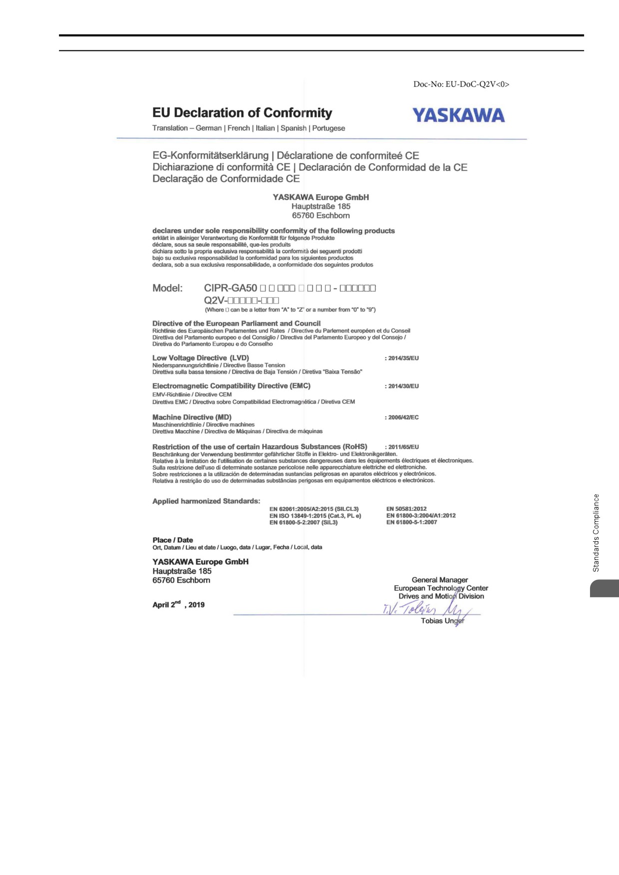
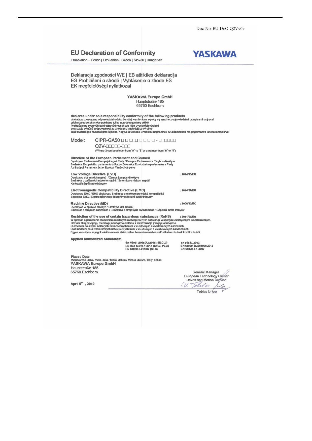
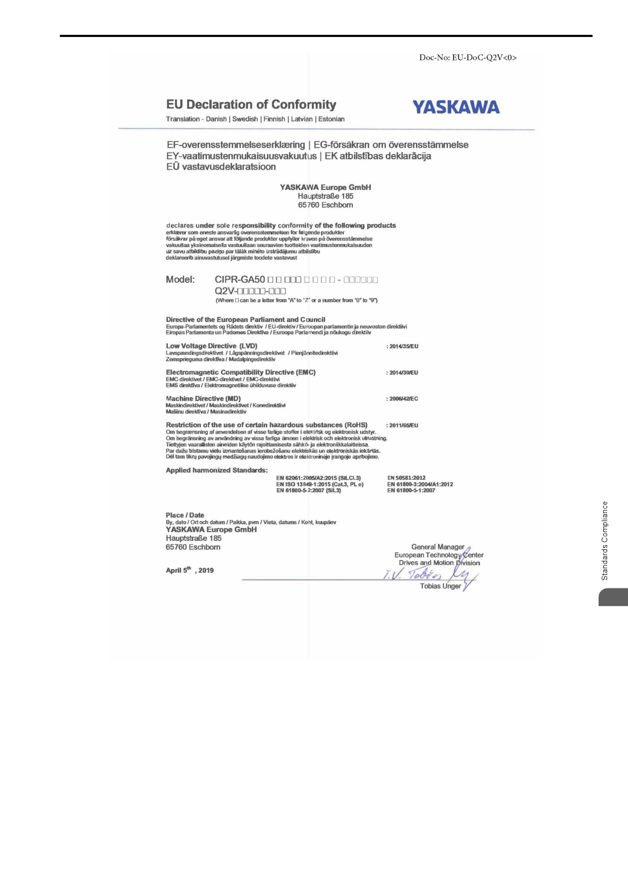
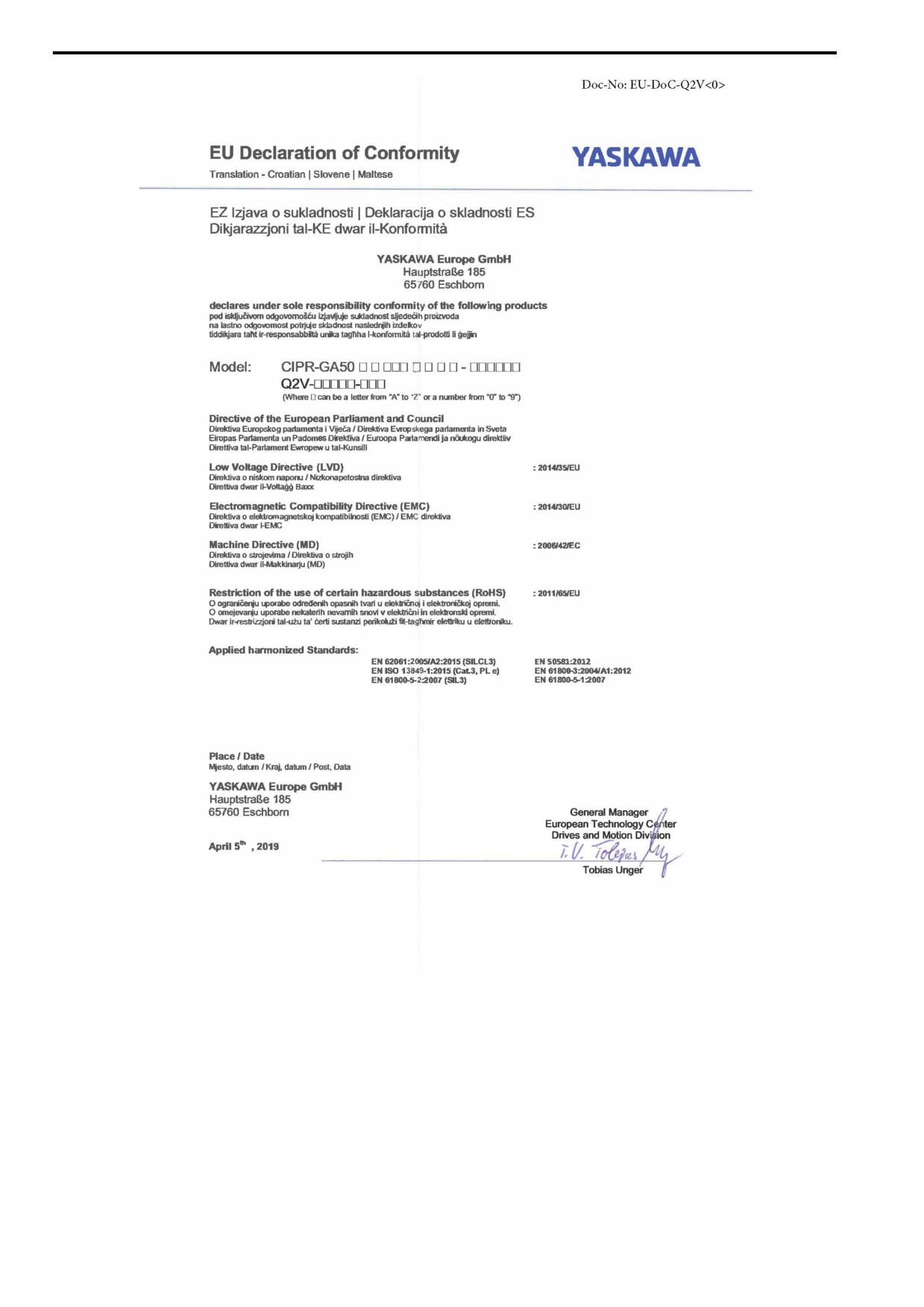
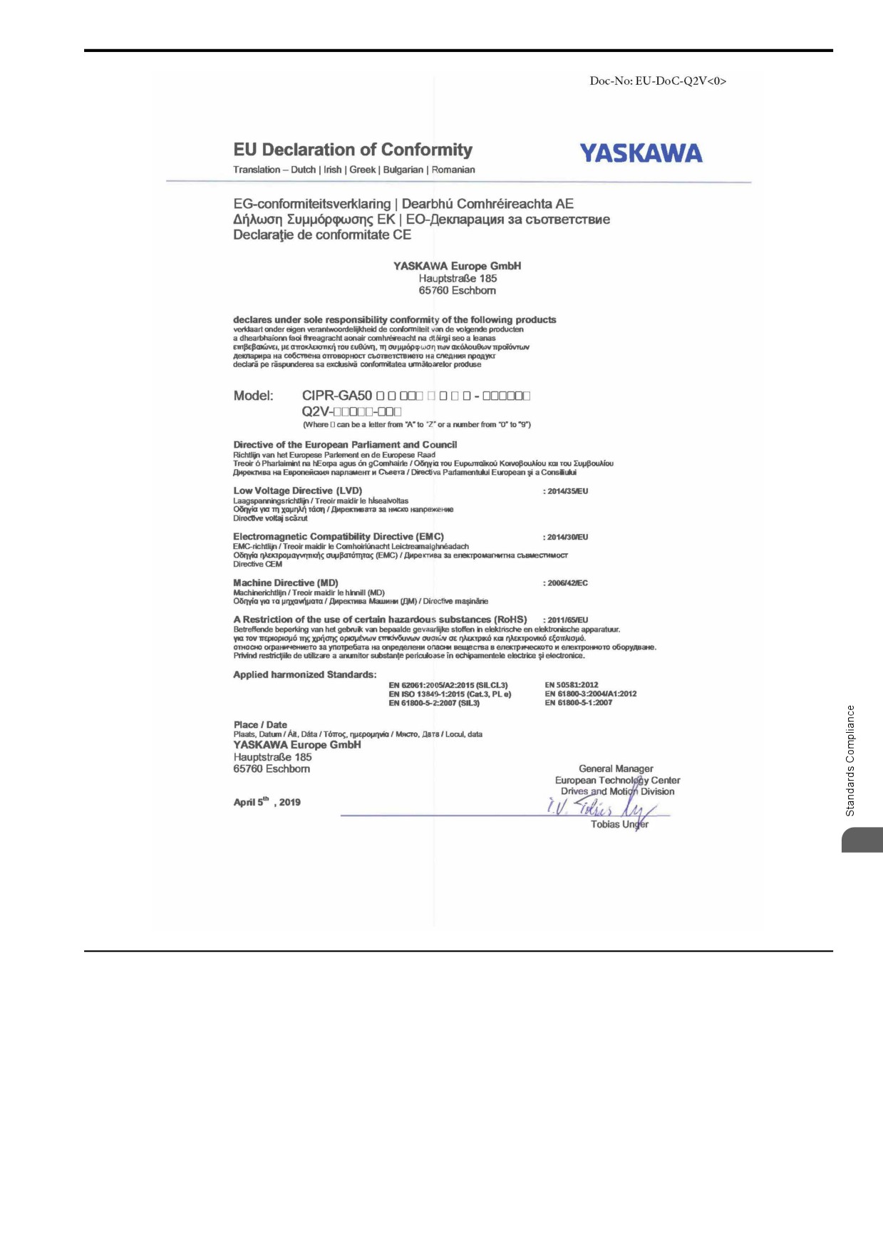
◆ EU Declaration of Conformity
5
143
5.2 European Standards
144
5.2 European Standards
5
145
5.2 European Standards
146
5.2 European Standards
5
◆ CE Low Voltage Directive Compliance
This product is tested according to IEC/EN 61800-5-1:2007 and complies with the CE Low Voltage Directive.
The following conditions must be satisfied for machines and devices incorporating this product to comply with
the CE Low Voltage Directive.
■ Area of Use
Install this product in a location with Overvoltage Category III and pollution degree 2 or less as specified in IEC/
CE 60664.
147
5.2 European Standards
■ Guarding Against Debris
When you install IP20/UL Open type drives, use an enclosure that does not let unwanted material enter the drive
from above or below.
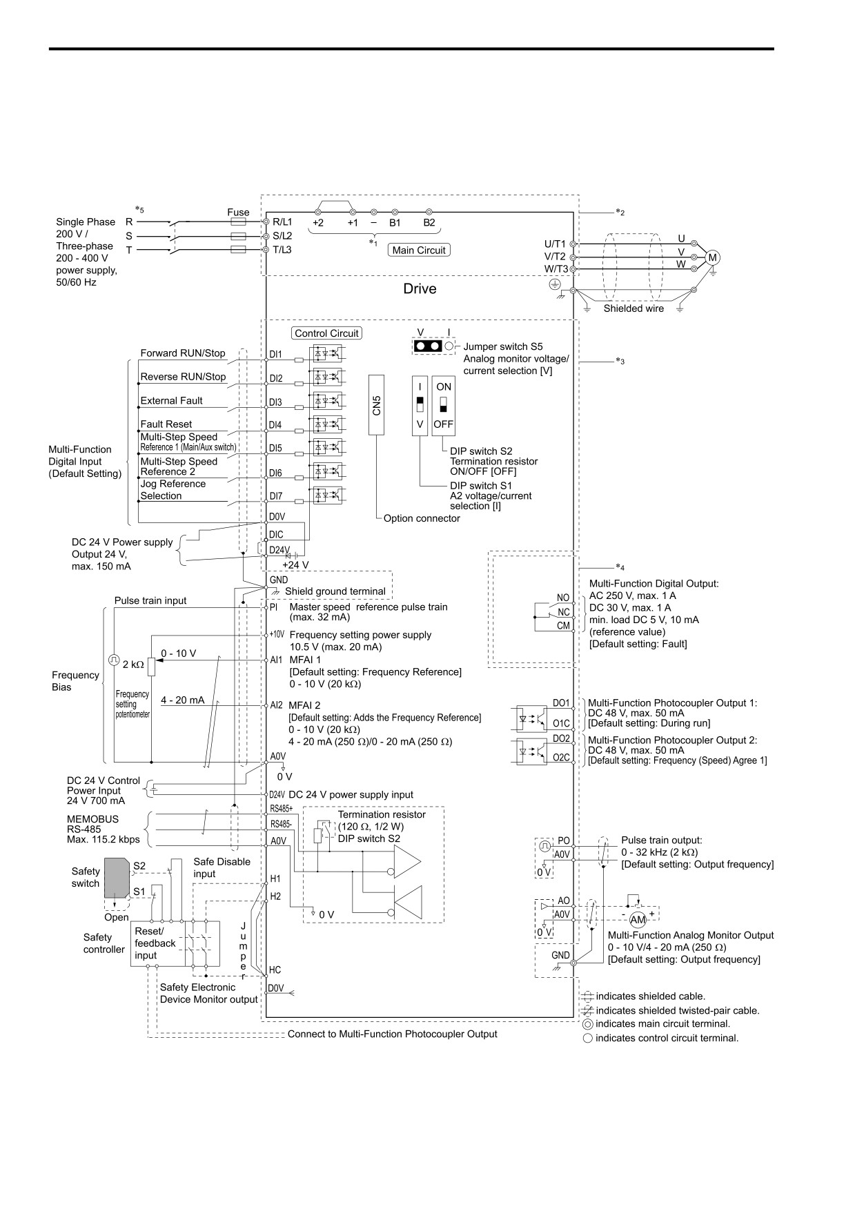
■ Wiring Diagram
Example of a drive that is wired to comply with the CE Low Voltage Directive.
Figure 5.2 Wiring Diagram for CE Low Voltage Directive Compliance
148
5.2 European Standards
*1
Use terminals -, +1, +2, B1, and B2 to connect options to the drive.
WARNING! Fire Hazard. Only connect factory-recommended devices or circuits to drive terminals B1, B2, -, +1, +2, and
+3 terminals. Do not connect AC power to these terminals. Incorrect wiring can cause damage to the drive and serious
injury or death from fire.
*2
For circuit protection, the main circuit is separated from the surface case that can touch the main circuit.
*3
The control circuit is a Safety Extra-Low Voltage circuit. Separate this circuit from other circuits with reinforced insulation. Make
sure that the Safety Extra-Low Voltage circuit is connected as specified.
*4
Reinforced insulation separates the output terminals from other circuits. Users can also connect circuits that are not Safety Extra-Low
Voltage circuits if the drive output is 250 Vac 1 A maximum or 30 Vdc 1 A maximum.
*5
Set L8-05 = 1 [In PhaseLoss Selection = Enabled] or set the wiring sequence to prevent input phase loss.
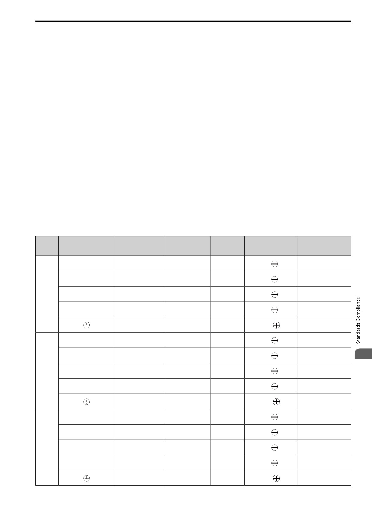
■ Main Circuit Wire Gauges and Tightening Torques (CE-compliance)
WARNING! Electrical Shock Hazard. Make sure that the protective ground wire complies with technical standards and local
safety regulations. The EN 61800-5-1: 2007 standard specifies that users must wire the power supply to automatically turn off
when the protective ground wire disconnects. If you turn on the internal EMC filter, the leakage current of the drive will be more
than 3.5 mA. You can also connect a protective ground wire that has a minimum cross-sectional area of 10 mm 2 (copper wire).
If you do not obey the standards and regulations, it can cause serious injury or death.
WARNING! Electrical Shock Hazard. Only connect peripheral options, for example a DC reactor or braking resistor, to terminals
+1, +2, -, B1, and B2. Failure to obey can cause serious injury or death.
Note:
• The recommended wire gauges are based on drive continuous current ratings with 75 °C (167 °F) 600 V class 2 heat-resistant indoor
PVC wire. Assume these conditions:
-Ambient temperature: 40 °C (104 °F) maximum
-Wiring distance: 100 m (3281 ft) maximum
-Normal Duty rated current value
• Refer to the instruction manual for each device for recommended wire gauges to connect peripheral devices or options to terminals +1,
+2, -, B1, and B2. Contact the manufacturer or your nearest sales representative if the recommended wire gauges for the peripheral
devices or options are out of the range of the applicable gauges for the drive.
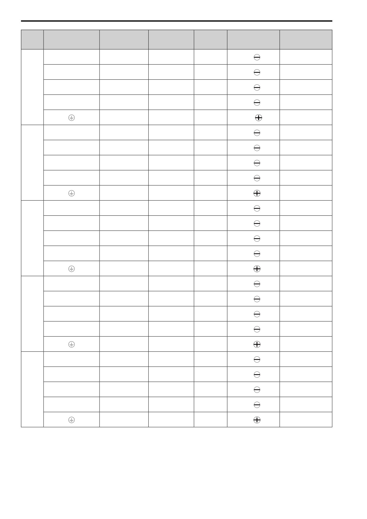
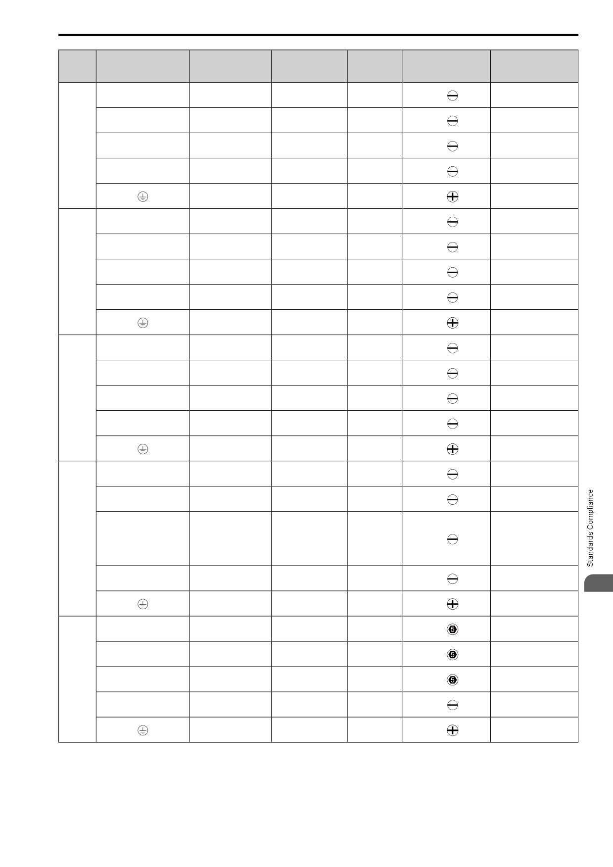
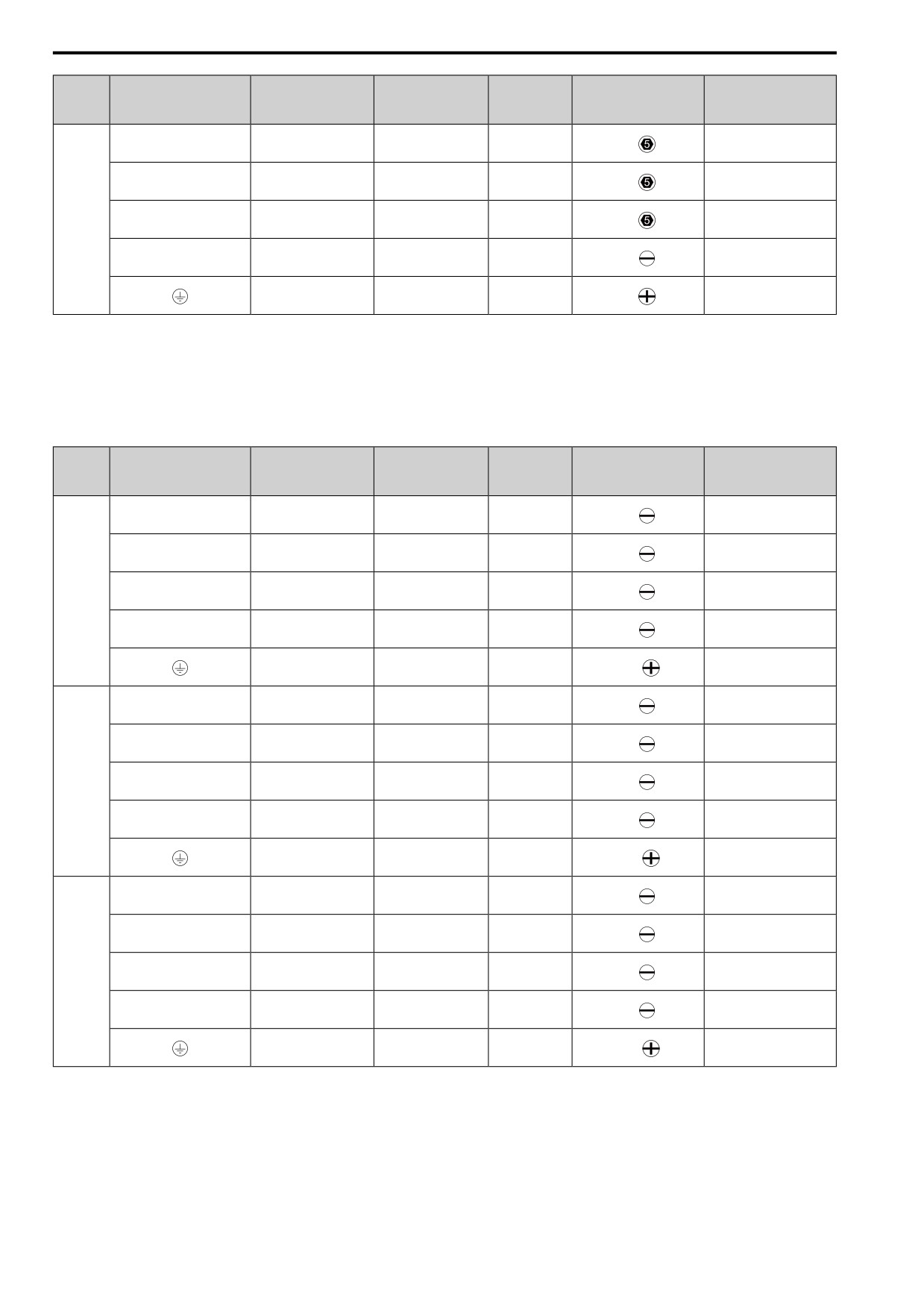
Three-Phase 200 V Class (CE-compliance)
Wire Stripping
Recommended Gauge
Applicable Gauge
Tightening Torque
Model
Terminal
Length *1
Terminal Screw
mm2
mm2
N∙m (in∙lb)
mm
0.5
- 0.6
R/L1, S/L2, T/L3
2.5
2.5
6.5
M3
(4.4
- 5.3)
0.5
- 0.6
U/T1, V/T2, W/T3
2.5
2.5
6.5
M3
(4.4
- 5.3)
0.5
- 0.6
2001
-, +1, +2
2.5
2.5
6.5
M3
(4.4
- 5.3)
0.5
- 0.6
B1, B2
2.5
2.5
6.5
M3
(4.4
- 5.3)
0.8
- 1.0
2.5 *2
2.5 *2
-
M3.5
(7.1
- 8.9)
0.5
- 0.6
R/L1, S/L2, T/L3
2.5
2.5
6.5
M3
(4.4
- 5.3)
0.5
- 0.6
U/T1, V/T2, W/T3
2.5
2.5
6.5
5
M3
(4.4
- 5.3)
0.5
- 0.6
2002
-, +1, +2
2.5
2.5
6.5
M3
(4.4
- 5.3)
0.5
- 0.6
B1, B2
2.5
2.5
6.5
M3
(4.4
- 5.3)
0.8
- 1.0
2.5 *2
2.5 *2
-
M3.5
(7.1
- 8.9)
0.5
- 0.6
R/L1, S/L2, T/L3
2.5
2.5
6.5
M3
(4.4
- 5.3)
0.5
- 0.6
U/T1, V/T2, W/T3
2.5
2.5
6.5
M3
(4.4
- 5.3)
0.5
- 0.6
2004
-, +1, +2
2.5
2.5
6.5
M3
(4.4
- 5.3)
0.5
- 0.6
B1, B2
2.5
2.5
6.5
M3
(4.4
- 5.3)
0.8
- 1.0
2.5 *2
2.5 *2
-
M3.5
(7.1
- 8.9)
149
5.2 European Standards
Wire Stripping
Recommended Gauge
Applicable Gauge
Tightening Torque
Model
Terminal
Length *1
Terminal Screw
mm2
mm2
N∙m (in∙lb)
mm
0.5
- 0.6
R/L1, S/L2, T/L3
2.5
2.5
6.5
M3
(4.4
- 5.3)
0.5
- 0.6
U/T1, V/T2, W/T3
2.5
2.5
6.5
M3
(4.4
- 5.3)
0.5
- 0.6
2006
-, +1, +2
2.5
2.5
6.5
M3
(4.4
- 5.3)
0.5
- 0.6
B1, B2
2.5
2.5
6.5
M3
(4.4
- 5.3)
0.8
- 1.0
2.5 *2
2.5 *2
-
M3.5
(7.1
- 8.9)
0.5
- 0.6
R/L1, S/L2, T/L3
2.5
2.5 - 4
8
M3
(4.4
- 5.3)
0.5
- 0.6
U/T1, V/T2, W/T3
2.5
2.5 - 4
8
M3
(4.4
- 5.3)
0.5
- 0.6
2008
-, +1, +2
2.5
2.5 - 4
8
M3
(4.4
- 5.3)
0.5
- 0.6
B1, B2
2.5
2.5 - 4
8
M3
(4.4
- 5.3)
1.2
- 1.5
4 *2
2.5 - 6 *2
-
M4
(10.6
- 13.3)
0.5
- 0.6
R/L1, S/L2, T/L3
2.5
2.5 - 4
8
M3
(4.4
- 5.3)
0.5
- 0.6
U/T1, V/T2, W/T3
2.5
2.5 - 4
8
M3
(4.4
- 5.3)
0.5
- 0.6
2010
-, +1, +2
2.5
2.5 - 4
8
M3
(4.4
- 5.3)
0.5
- 0.6
B1, B2
2.5
2.5 - 4
8
M3
(4.4
- 5.3)
1.2
- 1.5
4 *2
2.5 - 6 *2
-
M4
(10.6
- 13.3)
0.5
- 0.6
R/L1, S/L2, T/L3
2.5
2.5 - 4
8
M3
(4.4
- 5.3)
0.5
- 0.6
U/T1, V/T2, W/T3
2.5
2.5 - 4
8
M3
(4.4
- 5.3)
0.5
- 0.6
2012
-, +1, +2
2.5
2.5 - 4
8
M3
(4.4
- 5.3)
0.5
- 0.6
B1, B2
2.5
2.5 - 4
8
M3
(4.4
- 5.3)
1.2
- 1.5
4 *2
2.5 - 6 *2
-
M4
(10.6
- 13.3)
1.5
- 1.7
R/L1, S/L2, T/L3
2.5
2.5 - 4
10
M4
(13.5 - 15)
1.5
- 1.7
U/T1, V/T2, W/T3
2.5
2.5 - 4
10
M4
(13.5 - 15)
1.5
- 1.7
2018
-, +1, +2
4
2.5 - 6
10
M4
(13.5 - 15)
1.5
- 1.7
B1, B2
2.5
2.5 - 4
10
M4
(13.5 - 15)
1.2
- 1.5
6 *2
2.5 - 6 *2
-
M4
(10.6
- 13.3)
150
5.2 European Standards
Wire Stripping
Recommended Gauge
Applicable Gauge
Tightening Torque
Model
Terminal
Length *1
Terminal Screw
mm2
mm2
N∙m (in∙lb)
mm
1.5
- 1.7
R/L1, S/L2, T/L3
4
2.5 - 6
10
M4
(13.5 - 15)
1.5
- 1.7
U/T1, V/T2, W/T3
2.5
2.5 - 4
10
M4
(13.5 - 15)
1.5
- 1.7
2021
-, +1, +2
6
4 - 10
10
M4
(13.5 - 15)
1.5
- 1.7
B1, B2
2.5
2.5 - 4
10
M4
(13.5 - 15)
1.2
- 1.5
6 *2
2.5 - 6 *2
-
M4
(10.6
- 13.3)
1.5
- 1.7
R/L1, S/L2, T/L3
6
4 - 10
10
M4
(13.5 - 15)
1.5
- 1.7
U/T1, V/T2, W/T3
6
4 - 10
10
M4
(13.5 - 15)
1.5
- 1.7
2030
-, +1, +2
10
2.5 - 16
10
M4
(13.5 - 15)
1.5
- 1.7
B1, B2
2.5
2.5 - 4
10
M4
(13.5 - 15)
2.0
- 2.5
6 *2
6 - 16
-
M5
(17.7
- 22.1)
1.5
- 1.7
R/L1, S/L2, T/L3
10
2.5 - 16
10
M4
(13.5 - 15)
1.5
- 1.7
U/T1, V/T2, W/T3
10
2.5 - 16
10
M4
(13.5 - 15)
2.3
- 2.5
2042
-, +1, +2
16
4 - 25
18
M5
(19.8 - 22)
1.5
- 1.7
B1, B2
4
2.5 - 6
10
M4
(13.5 - 15)
2.0
- 2.5
10
6 - 16
-
M5
(17.7
- 22.1)
2.3
- 2.5
R/L1, S/L2, T/L3
16
4 - 25
18
M5
(19.8 - 22)
2.3
- 2.5
U/T1, V/T2, W/T3
16
4 - 25
18
M5
(19.8 - 22)
•
≤ 25 mm2
2.3
- 2.5
(19.8 - 22)
2056
-, +1, +2
25
6 - 35
18
M5
•
35 mm2 ≤
4.1
- 4.5
(36 - 40)
1.5
- 1.7
B1, B2
10
4 - 16
10
M4
(13.5 - 15)
5
5.4
- 6.0
10
10 - 25
-
M6
(47.8
- 53.1)
5 - 5.5
R/L1, S/L2, T/L3
25
6 - 35
20
M6
(45 - 49)
5 - 5.5
U/T1, V/T2, W/T3
16
6 - 25
20
M6
(45 - 49)
5 - 5.5
2070
-, +1, +2
35
10 - 50
20
M6
(45 - 49)
1.5
- 1.7
B1, B2
10
4 - 16
10
M4
(13.5 - 15)
5.4
- 6.0
16
10 - 25
-
M6
(47.8
- 53.1)
151
5.2 European Standards
Wire Stripping
Recommended Gauge
Applicable Gauge
Tightening Torque
Model
Terminal
Length *1
Terminal Screw
mm2
mm2
N∙m (in∙lb)
mm
5 - 5.5
R/L1, S/L2, T/L3
35
10 - 50
20
M6
(45 - 49)
5 - 5.5
U/T1, V/T2, W/T3
25
10 - 35
20
M6
(45 - 49)
5 - 5.5
2082
-, +1, +2
50
16 - 70
20
M6
(45 - 49)
1.5
- 1.7
B1, B2
16
4 - 16
10
M4
(13.5 - 15)
5.4
- 6.0
16
10 - 25
-
M6
(47.8
- 53.1)
*1
Remove insulation from the ends of wires to expose the length of wire shown.
*2
If you turn on the internal EMC filter, the leakage current of the drive will be more than 3.5 mA. Use these closed-loop crimp
terminals or equivalent to connect a protective ground wire that has a minimum cross-sectional area of 10 mm2
(copper wire).
•
8-4NS from JST Mfg. Co., Ltd.
• R8-4S from NICHIFU Co.,Ltd.
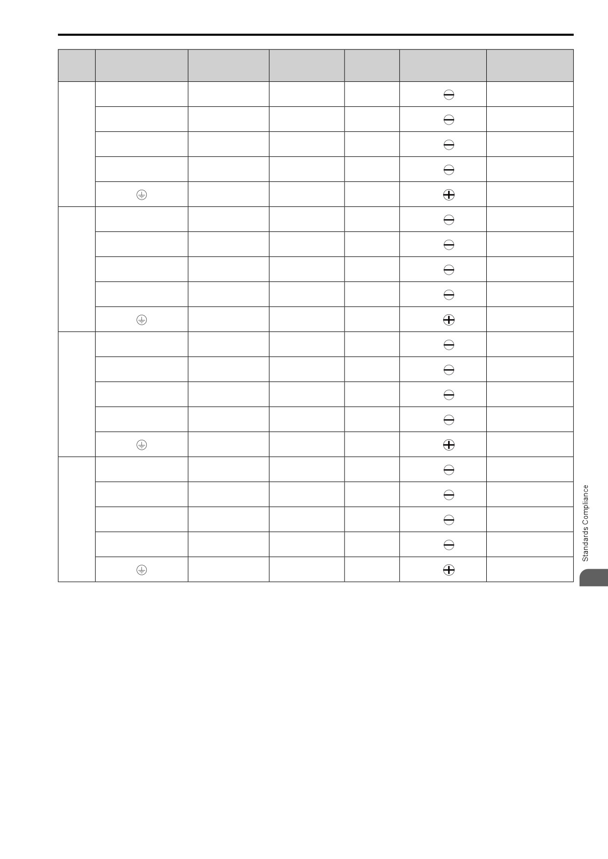
Single-Phase 200 V Class (CE-compliance)
Wire Stripping
Recommended Gauge
Applicable Gauge
Tightening Torque
Model
Terminal
Length *1
Terminal Screw
mm2
mm2
N∙m (in∙lb)
mm
0.5
- 0.6
L/L1, N/L2
2.5
2.5
6.5
M3
(4.4
- 5.3)
0.5
- 0.6
U/T1, V/T2, W/T3
2.5
2.5
6.5
M3
(4.4
- 5.3)
0.5
- 0.6
B001
-, +1
2.5
2.5
6.5
M3
(4.4
- 5.3)
0.5
- 0.6
B1, B2
2.5
2.5
6.5
M3
(4.4
- 5.3)
0.8
- 1.0
2.5 *2
2.5 *2
-
M3.5
(7.1
- 8.9)
0.5
- 0.6
L/L1, N/L2
2.5
2.5
6.5
M3
(4.4
- 5.3)
0.5
- 0.6
U/T1, V/T2, W/T3
2.5
2.5
6.5
M3
(4.4
- 5.3)
0.5
- 0.6
B002
-, +1
2.5
2.5
6.5
M3
(4.4
- 5.3)
0.5
- 0.6
B1, B2
2.5
2.5
6.5
M3
(4.4
- 5.3)
0.8
- 1.0
2.5 *2
2.5 *2
-
M3.5
(7.1
- 8.9)
0.5
- 0.6
L/L1, N/L2
2.5
2.5
6.5
M3
(4.4
- 5.3)
0.5
- 0.6
U/T1, V/T2, W/T3
2.5
2.5
6.5
M3
(4.4
- 5.3)
0.5
- 0.6
B004
-, +1
2.5
2.5
6.5
M3
(4.4
- 5.3)
0.5
- 0.6
B1, B2
2.5
2.5
6.5
M3
(4.4
- 5.3)
0.8
- 1.0
2.5 *2
2.5 *2
-
M3.5
(7.1
- 8.9)
152
5.2 European Standards
Wire Stripping
Recommended Gauge
Applicable Gauge
Tightening Torque
Model
Terminal
Length *1
Terminal Screw
mm2
mm2
N∙m (in∙lb)
mm
0.5
- 0.6
L/L1, N/L2
2.5
2.5 - 4
8
M3
(4.4
- 5.3)
0.5
- 0.6
U/T1, V/T2, W/T3
2.5
2.5 - 4
8
M3
(4.4
- 5.3)
0.5
- 0.6
B006
-, +1
2.5
2.5 - 4
8
M3
(4.4
- 5.3)
0.5
- 0.6
B1, B2
2.5
2.5 - 4
8
M3
(4.4
- 5.3)
1.2
- 1.5
2.5 *2
2.5 - 6 *2
-
M4
(10.6
- 13.3)
0.5
- 0.6
L/L1, N/L2
2.5
2.5 - 4
8
M3
(4.4
- 5.3)
0.5
- 0.6
U/T1, V/T2, W/T3
2.5
2.5 - 4
8
M3
(4.4
- 5.3)
0.5
- 0.6
B010
-, +1
2.5
2.5 - 4
8
M3
(4.4
- 5.3)
0.5
- 0.6
B1, B2
2.5
2.5 - 4
8
M3
(4.4
- 5.3)
1.2
- 1.5
2.5 *2
2.5 - 6 *2
-
M4
(10.6
- 13.3)
1.5
- 1.7
L/L1, N/L2
4
2.5 - 6
10
M4
(13.5 - 15)
1.5
- 1.7
U/T1, V/T2, W/T3
2.5
2.5 - 4
10
M4
(13.5 - 15)
1.5
- 1.7
B012
-, +1
4
2.5 - 6
10
M4
(13.5 - 15)
1.5
- 1.7
B1, B2
2.5
2.5 - 4
10
M4
(13.5 - 15)
1.2
- 1.5
4 *2
2.5 - 6 *2
-
M4
(10.6
- 13.3)
1.5
- 1.7
L/L1, N/L2
6
2.5 - 10
10
M4
(13.5 - 15)
1.5
- 1.7
U/T1, V/T2, W/T3
2.5
2.5 - 4
10
M4
(13.5 - 15)
1.5
- 1.7
B018
-, +1
6
2.5 - 10
10
M4
(13.5 - 15)
1.5
- 1.7
B1, B2
2.5
2.5 - 4
10
M4
(13.5 - 15)
2.0
- 2.5
6 *2
4 - 10 *2
-
M5
(17.7
- 22.1)
5
*1
Remove insulation from the ends of wires to expose the length of wire shown.
*2
If you turn on the internal EMC filter, the leakage current of the drive will be more than 3.5 mA. Use these closed-loop crimp
terminals or equivalent to connect a protective ground wire that has a minimum cross-sectional area of 10 mm2 (copper wire).
• 8-4NS from JST Mfg. Co., Ltd.
• R8-4S from NICHIFU Co.,Ltd.
153
5.2 European Standards
Three-Phase 400 V Class (CE-compliance)
Wire Stripping
Recommended Gauge
Applicable Gauge
Tightening Torque
Model
Terminal
Length *1
Terminal Screw
mm2
mm2
N∙m (in∙lb)
mm
0.5
- 0.6
R/L1, S/L2, T/L3
2.5
2.5 - 4
8
M3
(4.4
- 5.3)
0.5
- 0.6
U/T1, V/T2, W/T3
2.5
2.5 - 4
8
M3
(4.4
- 5.3)
0.5
- 0.6
4001
-, +1, +2
2.5
2.5 - 4
8
M3
(4.4
- 5.3)
0.5
- 0.6
B1, B2
2.5
2.5 - 4
8
M3
(4.4
- 5.3)
1.2
- 1.5
2.5 *2
2.5 - 6 *2
-
M4
(10.6
- 13.3)
0.5
- 0.6
R/L1, S/L2, T/L3
2.5
2.5 - 4
8
M3
(4.4
- 5.3)
0.5
- 0.6
U/T1, V/T2, W/T3
2.5
2.5 - 4
8
M3
(4.4
- 5.3)
0.5
- 0.6
4002
-, +1, +2
2.5
2.5 - 4
8
M3
(4.4
- 5.3)
0.5
- 0.6
B1, B2
2.5
2.5 - 4
8
M3
(4.4
- 5.3)
1.2
- 1.5
2.5 *2
2.5 - 6 *2
-
M4
(10.6
- 13.3)
0.5
- 0.6
R/L1, S/L2, T/L3
2.5
2.5 - 4
8
M3
(4.4
- 5.3)
0.5
- 0.6
U/T1, V/T2, W/T3
2.5
2.5 - 4
8
M3
(4.4
- 5.3)
0.5
- 0.6
4004
-, +1, +2
2.5
2.5 - 4
8
M3
(4.4
- 5.3)
0.5
- 0.6
B1, B2
2.5
2.5 - 4
8
M3
(4.4
- 5.3)
1.2
- 1.5
4 *2
2.5 - 6 *2
-
M4
(10.6
- 13.3)
0.5
- 0.6
R/L1, S/L2, T/L3
2.5
2.5 - 4
8
M3
(4.4
- 5.3)
0.5
- 0.6
U/T1, V/T2, W/T3
2.5
2.5 - 4
8
M3
(4.4
- 5.3)
0.5
- 0.6
4005
-, +1, +2
2.5
2.5 - 4
8
M3
(4.4
- 5.3)
0.5
- 0.6
B1, B2
2.5
2.5 - 4
8
M3
(4.4
- 5.3)
1.2
- 1.5
4 *2
2.5 - 6 *2
-
M4
(10.6
- 13.3)
0.5
- 0.6
R/L1, S/L2, T/L3
2.5
2.5 - 4
8
M3
(4.4
- 5.3)
0.5
- 0.6
U/T1, V/T2, W/T3
2.5
2.5 - 4
8
M3
(4.4
- 5.3)
0.5
- 0.6
4007
-, +1, +2
2.5
2.5 - 4
8
M3
(4.4
- 5.3)
0.5
- 0.6
B1, B2
2.5
2.5 - 4
8
M3
(4.4
- 5.3)
1.2
- 1.5
4 *2
2.5 - 6 *2
-
M4
(10.6
- 13.3)
154
5.2 European Standards
Wire Stripping
Recommended Gauge
Applicable Gauge
Tightening Torque
Model
Terminal
Length *1
Terminal Screw
mm2
mm2
N∙m (in∙lb)
mm
0.5
- 0.6
R/L1, S/L2, T/L3
2.5
2.5 - 4
8
M3
(4.4
- 5.3)
0.5
- 0.6
U/T1, V/T2, W/T3
2.5
2.5 - 4
8
M3
(4.4
- 5.3)
0.5
- 0.6
4009
-, +1, +2
2.5
2.5 - 4
8
M3
(4.4
- 5.3)
0.5
- 0.6
B1, B2
2.5
2.5 - 4
8
M3
(4.4
- 5.3)
1.2
- 1.5
4 *2
2.5 - 6 *2
-
M4
(10.6
- 13.3)
1.5
- 1.7
R/L1, S/L2, T/L3
2.5
2.5 - 4
10
M4
(13.5 - 15)
1.5
- 1.7
U/T1, V/T2, W/T3
2.5
2.5 - 4
10
M4
(13.5 - 15)
1.5
- 1.7
4012
-, +1, +2
2.5
2.5 - 4
10
M4
(13.5 - 15)
1.5
- 1.7
B1, B2
2.5
2.5 - 4
10
M4
(13.5 - 15)
1.2
- 1.5
4 *2
2.5 - 6 *2
-
M4
(10.6
- 13.3)
1.5
- 1.7
R/L1, S/L2, T/L3
2.5
2.5 - 4
10
M4
(13.5 - 15)
1.5
- 1.7
U/T1, V/T2, W/T3
2.5
2.5 - 4
10
M4
(13.5 - 15)
1.5
- 1.7
4018
-, +1, +2
4
2.5 - 6
10
M4
(13.5 - 15)
1.5
- 1.7
B1, B2
2.5
2.5 - 4
10
M4
(13.5 - 15)
2.0
- 2.5
4 *2
2.5 - 16
-
M5
(17.7
- 22.1)
1.5
- 1.7
R/L1, S/L2, T/L3
4
2.5 - 6
10
M4
(13.5 - 15)
1.5
- 1.7
U/T1, V/T2, W/T3
4
2.5 - 6
10
M4
(13.5 - 15)
1.5
- 1.7
4023
-, +1, +2
4
4-6
10
M4
(13.5 - 15)
1.5
- 1.7
B1, B2
2.5
2.5 - 4
10
M4
(13.5 - 15)
2.0
- 2.5
4 *2
4 - 16
-
M5
(17.7
- 22.1)
5
1.5
- 1.7
R/L1, S/L2, T/L3
6
4 - 10
10
M4
(13.5 - 15)
1.5
- 1.7
U/T1, V/T2, W/T3
6
4 - 10
10
M4
(13.5 - 15)
2.3
- 2.5
4031
-, +1, +2
10
2.5 - 16
18
M5
(19.8 - 22)
1.5
- 1.7
B1, B2
2.5
2.5 - 4
10
M4
(13.5 - 15)
5.4
- 6.0
6 *2
6 - 16 *2
-
M6
(47.8
- 53.1)
155
5.2 European Standards
Wire Stripping
Recommended Gauge
Applicable Gauge
Tightening Torque
Model
Terminal
Length *1
Terminal Screw
mm2
mm2
N∙m (in∙lb)
mm
1.5
- 1.7
R/L1, S/L2, T/L3
10
4 - 16
10
M4
(13.5 - 15)
1.5
- 1.7
U/T1, V/T2, W/T3
6
2.5 - 10
10
M4
(13.5 - 15)
2.3
- 2.5
4038
-, +1, +2
16
4 - 25
18
M5
(19.8 - 22)
1.5
- 1.7
B1, B2
4
2.5 - 6
10
M4
(13.5 - 15)
5.4
- 6.0
10
6 - 16
-
M6
(47.8
- 53.1)
2.3
- 2.5
R/L1, S/L2, T/L3
16
4 - 25
18
M5
(19.8 - 22)
2.3
- 2.5
U/T1, V/T2, W/T3
10
4 - 16
18
M5
(19.8 - 22)
2.3
- 2.5
4044
-, +1, +2
16
6 - 25
18
M5
(19.8 - 22)
1.5
- 1.7
B1, B2
6
4 - 10
10
M4
(13.5 - 15)
5.4
- 6.0
10
6 - 16
-
M6
(47.8
- 53.1)
•
≤ 25 mm2
2.3
- 2.5
(19.8 - 22)
R/L1, S/L2, T/L3
25
6 - 35
18
M5
•
35 mm2 ≤
4.1
- 4.5
(36 - 40)
2.3
- 2.5
U/T1, V/T2, W/T3
16
4 - 25
18
M5
(19.8 - 22)
•
≤ 25 mm
2
4060
2.3
- 2.5
(19.8 - 22)
-, +1, +2
25
6 - 35
18
M5
•
35 mm2 ≤
4.1
- 4.5
(36 - 40)
1.5
- 1.7
B1, B2
10
2.5 - 16
10
M4
(13.5 - 15)
5.4
- 6.0
10
6 - 16
-
M6
(47.8
- 53.1)
*1
Remove insulation from the ends of wires to expose the length of wire shown.
*2
If you turn on the internal EMC filter, the leakage current of the drive will be more than 3.5 mA. Use these closed-loop crimp
terminals or equivalent to connect a protective ground wire that has a minimum cross-sectional area of 10 mm2 (copper wire).
•
8-4NS from JST Mfg. Co., Ltd.
• R8-4S from NICHIFU Co.,Ltd.
■ Connect a Fuse to the Input Side (Primary Side)
The drive circuit protection must comply with EN 61800-5-1:2007 for protection against a short circuit in the
internal circuitry. Connect semiconductor protection fuses on the input side for branch circuit protection.
WARNING! Electrical Shock Hazard. After the drive blows a fuse or trips an RCM/RCD, do not immediately energize the drive
or operate peripheral devices. Wait for the time specified on the warning label at a minimum and make sure that all indicators
are OFF. Then check the wiring and peripheral device ratings to find the cause of the problem. If you do not know the cause of
the problem, contact the manufacturer before you energize the drive or peripheral devices. If you do not fix the problem before
you operate the drive or peripheral devices, it can cause serious injury or death.
Three-Phase 200 V Class
Table 5.2 Factory-Recommended Branch Circuit Protection: Three-Phase 200 V Class
Semiconductor Protection Fuse Rated Current
Semiconductor Protection Fuse Rated Current
Drive Model
Drive Model
Manufacturer: EATON/Bussmann
Manufacturer: EATON/Bussmann
2001
FWH-25A14F
2006
FWH-25A14F
2008
FWH-70B
2002
FWH-25A14F
2004
FWH-25A14F
2010
FWH-70B
156
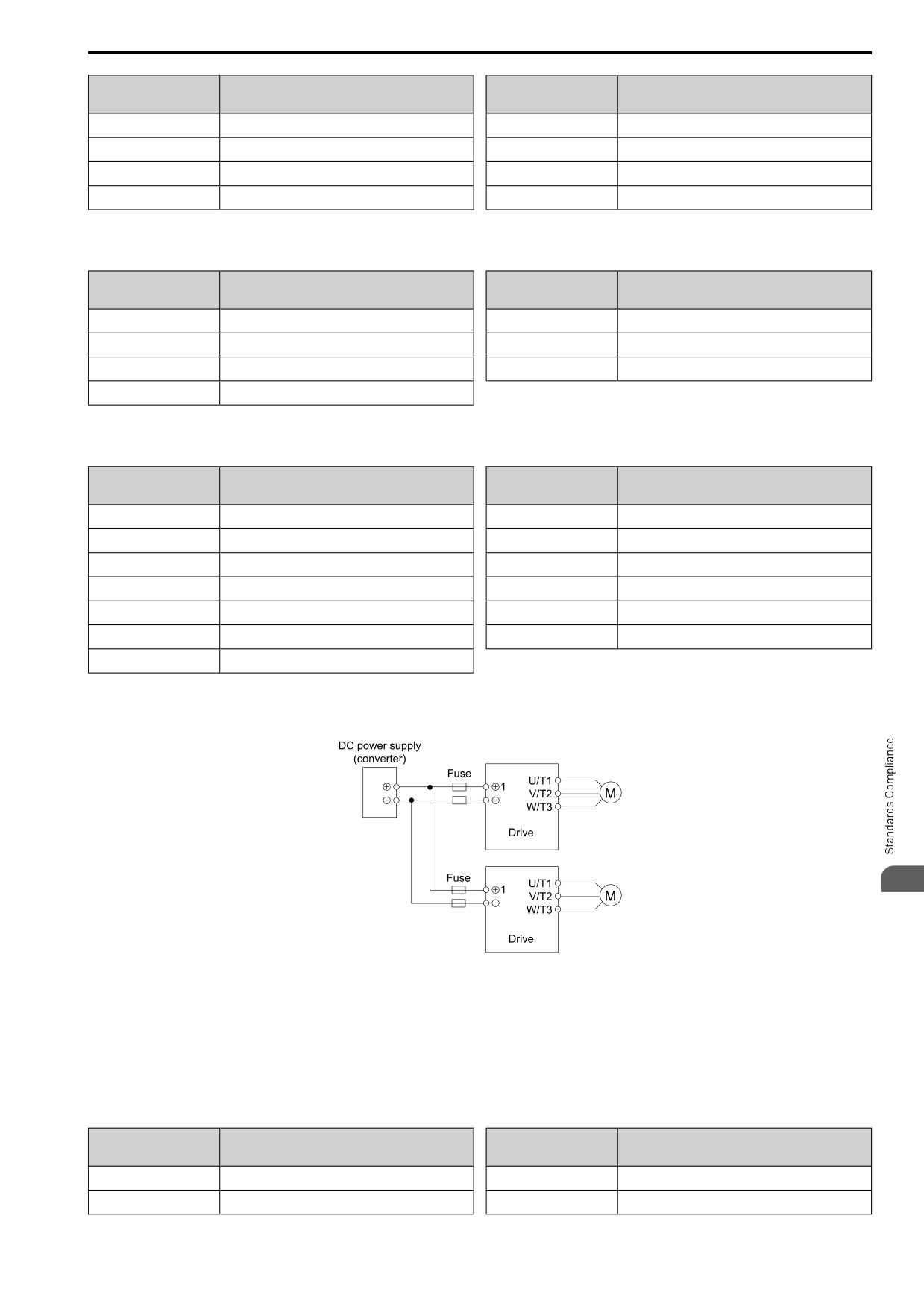
5.2 European Standards
Semiconductor Protection Fuse Rated Current
Semiconductor Protection Fuse Rated Current
Drive Model
Drive Model
Manufacturer: EATON/Bussmann
Manufacturer: EATON/Bussmann
2012
FWH-70B
2042
FWH-150B
2018
FWH-90B
2056
FWH-200B
2021
FWH-90B
2070
FWH-200B
2030
FWH-100B
2082
FWH-225A
Single-Phase 200 V Class
Table 5.3 Factory-Recommended Branch Circuit Protection: Single-Phase 200 V Class
Semiconductor Protection Fuse Rated Current
Semiconductor Protection Fuse Rated Current
Drive Model
Drive Model
Manufacturer: EATON/Bussmann
Manufacturer: EATON/Bussmann
B001
FWH-25A14F
B010
FWH-100B
B002
FWH-25A14F
B012
FWH-125B
B004
FWH-60B
B018
FWH-150B
B006
FWH-80B
Three-Phase 400 V Class
Table 5.4 Factory-Recommended Branch Circuit Protection: Three-Phase 400 V Class
Semiconductor Protection Fuse Rated Current
Semiconductor Protection Fuse Rated Current
Drive Model
Drive Model
Manufacturer: EATON/Bussmann
Manufacturer: EATON/Bussmann
4001
FWH-40B
4018
FWH-80B
4002
FWH-40B
4023
FWH-100B
4004
FWH-50B
4031
FWH-125B
4005
FWH-70B
4038
FWH-175B
4007
FWH-70B
4044
FWH-200B
4009
FWH-90B
4060
FWH-200B
4012
FWH-90B
■ CE Standards Compliance for DC Power Supply Input
To comply with CE Standards, install a fuse for the DC power supply input.
5
Two drives are connected in parallel.
Figure 5.3 Wiring Example for DC Power Supply Input
WARNING! Electrical Shock Hazard. Do not ground the main circuit bus. Incorrect wiring can cause serious injury or death.
Note:
• Install a fuse for each drive when operating more than one drive. If one fuse blows, replace all fuses.
• Install the external filter (system) to comply with the EMC Directive.
Table 5.5 Recommended Fuse: Three-Phase 200 V Class
Fuse
Fuse
Drive Model
Drive Model
Manufacturer: Bussmann
Manufacturer: Bussmann
2001
FWH-25A14F
2004
FWH-25A14F
2002
FWH-25A14F
2006
FWH-25A14F
157
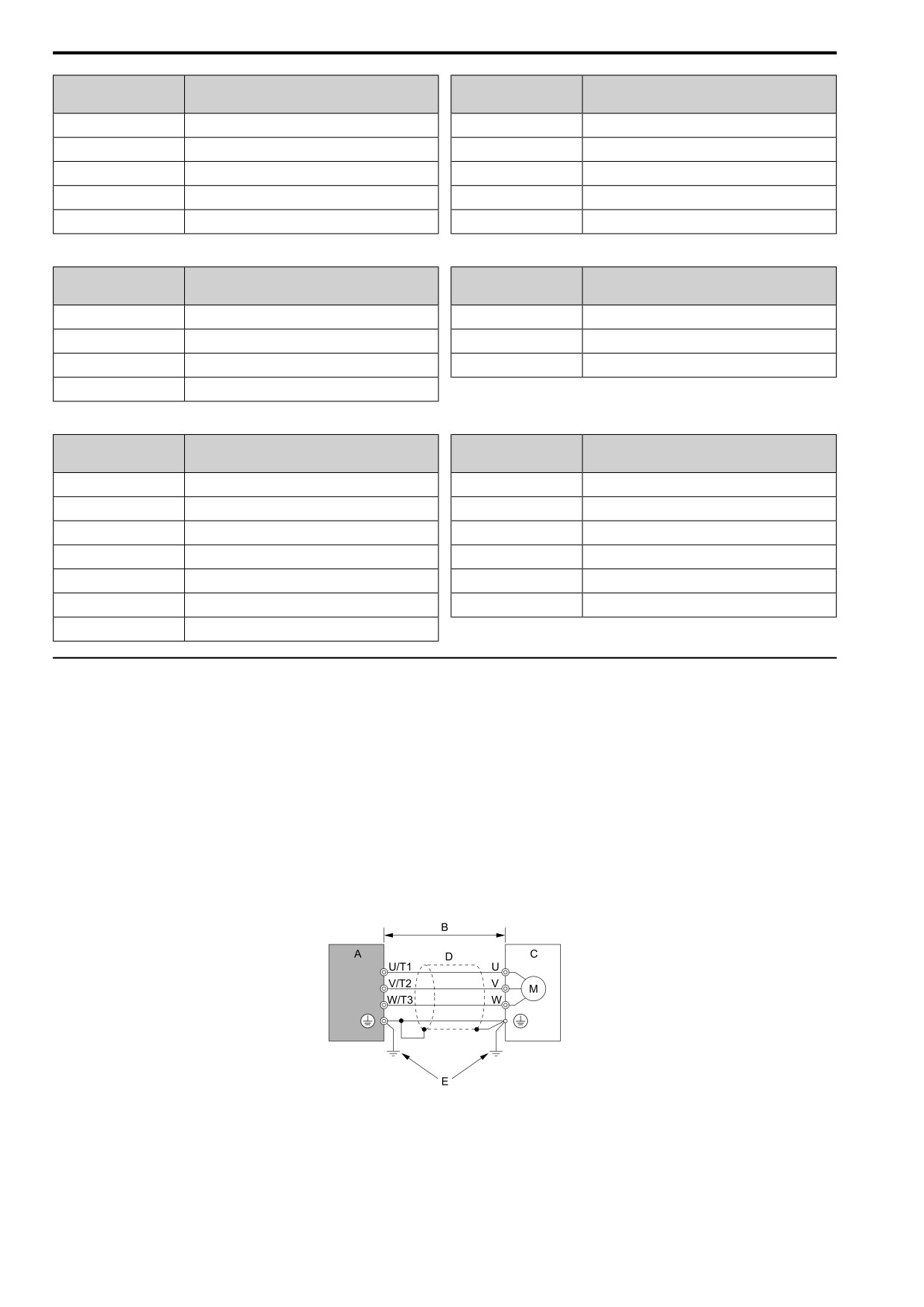
5.2
European Standards
Fuse
Fuse
Drive Model
Drive Model
Manufacturer: Bussmann
Manufacturer: Bussmann
2008
FWH-70B
2030
FWH-100B
2010
FWH-70B
2042
FWH-150B
2012
FWH-70B
2056
FWH-200B
2018
FWH-90B
2070
FWH-200B
2021
FWH-90B
2082
FWH-225A
Table 5.6 Recommended Fuse: Single-Phase 200 V Class
Fuse
Fuse
Drive Model
Drive Model
Manufacturer: Bussmann
Manufacturer: Bussmann
B001
FWH-25A14F
B010
FWH-100B
B002
FWH-25A14F
B012
FWH-125B
B004
FWH-60B
B018
FWH-150B
B006
FWH-80B
Table 5.7 Recommended Fuse: Three-Phase 400 V Class
Fuse
Fuse
Drive Model
Drive Model
Manufacturer: Bussmann
Manufacturer: Bussmann
4001
FWH-40B
4018
FWH-80B
4002
FWH-40B
4023
FWH-100B
4004
FWH-50B
4031
FWH-125B
4005
FWH-70B
4038
FWH-175B
4007
FWH-70B
4044
FWH-200B
4009
FWH-90B
4060
FWH-200B
4012
FWH-90B
◆ EMC Directive
Use drives with built-in EMC filters or install external EMC filters to the drive input side to comply with the
EMC Directive. Drives with built-in EMC filters were tested in accordance with European standard EN 61800-
3:2004/A1:2012, and comply with the EMC Directive.
■ Install a Drive to Conform to the EMC Directive
Install the drives with this procedure to comply with the EMC Directive when the drive is a single unit or installed
in a larger device.
1. Install the drive on a grounded metal plate.
2. Wire the drive and motor.
3. Ground the wire shielding on the drive side and motor side.
A - Drive
D - Metal conduit
B - Wiring length *1
E - Grounding wire
C - Motor
Figure 5.4 Wiring the Drive and Motor
158
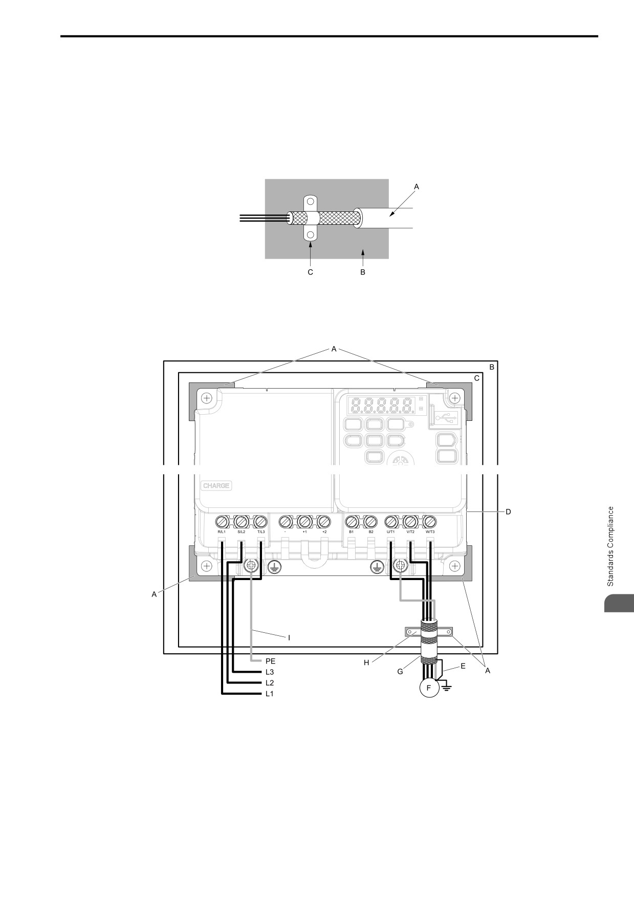
5.2 European Standards
*1
The maximum wiring length between the drive and motor is:
•
2xxx, 4xxx: 20 m (65.6 ft)
• Bxxx: 10 m (32.8 ft)
Note:
• Use a braided shield cable for the drive and motor wiring or put the wires through a metal conduit.
• Keep the cable between the drive and motor and the grounding wire as short as possible.
4. Use a cable clamp to ground the motor cable to the metal plate.
Note:
Make sure that the protective ground wire complies with technical specifications or local safety standards.
A - Braided shield cable
C - Cable clamp (conductive)
B - Metal plate
Figure 5.5 Ground the shield
5
A - Grounding surface (Remove any paint or
F - Motor
sealant.)
G - Motor cable
B - Enclosure panel
H - Cable clamp
C - Metal plate
I - Grounding wire
D - Drive
E - Shielded wire
Figure 5.6 Install a Drive with a Built-in EMC Filter
159