Q2V Driving Quality. Technical Manual (Item code: Q2V-Axxxx-xxx, 2020) - page 2
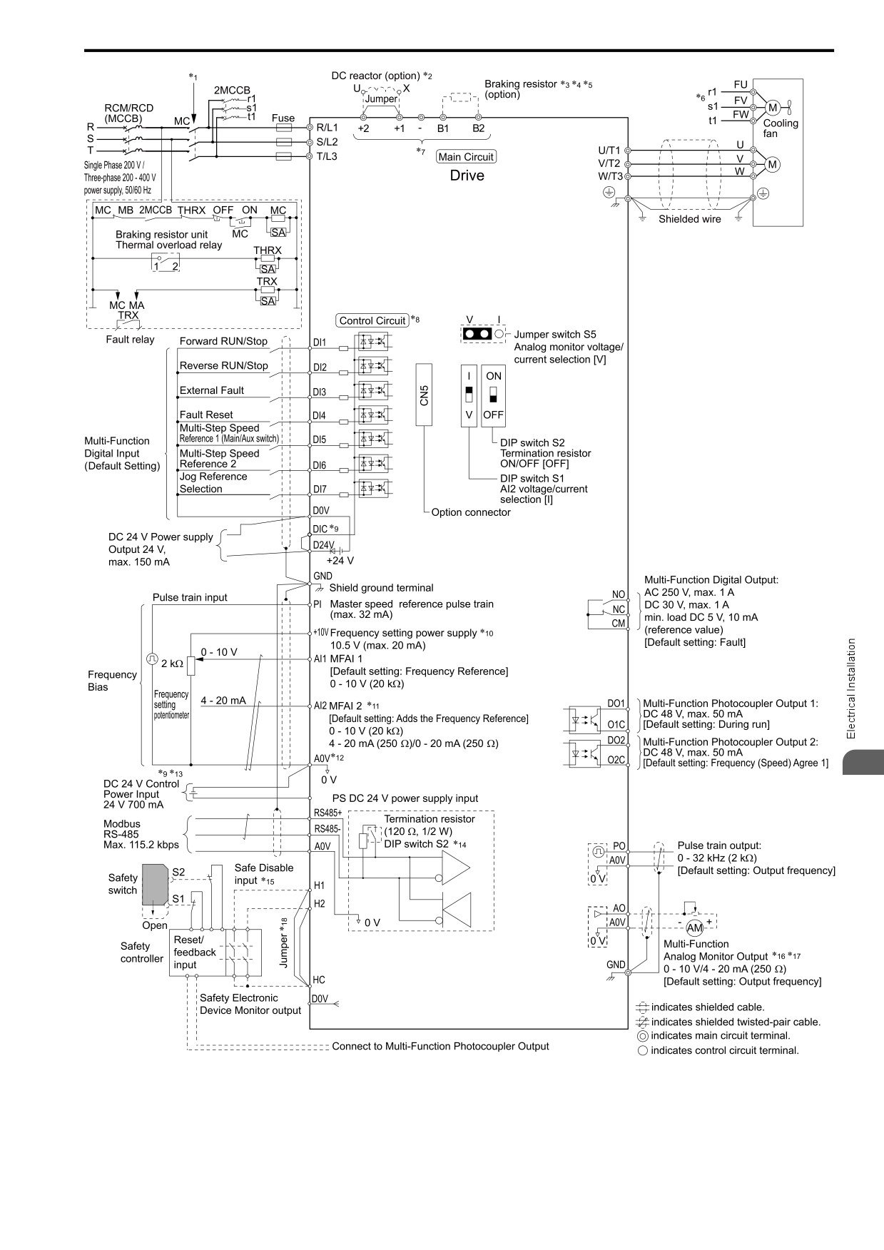
3.2 Standard Connection Diagram
3
E24
Figure 3.1 Standard Drive Connection Diagram
*1
Set the wiring sequence to de-energize the drive with the MFDO. If the drive outputs a fault during fault restart when you use the
fault restart function, set L5-02 = 2 [Fault@Reset Select = Enable Fault Output] to de-energize the drive. Be careful when you use a
cut-off sequence. The default setting for L5-02 is 1 [Disable Fault Output].
*2
When you install a DC reactor, you must remove the jumper between terminals +1 and +2.
43
3.2
Standard Connection Diagram
*3
When you use a regenerative converter or regenerative unit, set L8-55 = 0 [DB IGBT Protection = Disable]. If L8-55 = 1 [Enabled],
the drive will detect rF [Braking Resistor Fault].
*4
When you use a regenerative converter, regenerative unit, braking resistor, or braking resistor unit, set L3-04 = 0 [StallP@Decel
Enable = Disabled]. If L3-04 = 1 [Enabled], the drive could possibly not stop in the specified deceleration time.
*5
When you use an ERF-type braking resistor, set L8-01 = 1 [3%ERF DBR Protection = Enabled] and set a wiring sequence to de-
energize the drive with the MFDO.
*6
Cooling fan wiring is not necessary for self-cooling motors.
*7
Connect peripheral options to terminals -, +1, +2, B1, and B2.
WARNING! Fire Hazard. Only connect factory-recommended devices or circuits to drive terminals B1, B2, -, +1, +2, and
+3 terminals. Do not connect AC power to these terminals. Incorrect wiring can cause damage to the drive and serious
injury or death from fire.
*8
Connect a 24 V power supply to terminals E24V-A0V to operate the control circuit while the main circuit power supply is OFF.
*9
To set the MFDI power supply (Sinking/Sourcing Mode or internal/external power supply), install wire jumpers between terminals
DIC-D24V and DIC-D0V.
NOTICE: Do not close the circuit between terminals D24V and D0V. A closed circuit between these terminals will cause
damage to the drive.
• Sinking Mode: Install a jumper between terminals DIC and D24V.
NOTICE: Do not close the circuit between terminals DIC and D0V. A closed circuit between these terminals will cause
damage to the drive.
• Sourcing Mode: Install a jumper between terminals DIC and D0V.
NOTICE: Do not close the circuit between terminals DIC and D24V. A closed circuit between these terminals will cause
damage to the drive.
• External Power Supply: No jumper is necessary between terminals DIC-D0V and terminals DIC-D24V.
*10
The maximum output current capacity for terminal RS485+ on the control circuit is 20 mA.
NOTICE: Damage to Equipment. Do not install a jumper between terminals +10V and AC. A closed circuit between these
terminals will cause damage to the drive.
*11
DIP switch S1 sets terminal AI2 for voltage or current input. The default setting for S1 is current input (“I” side).
*12
Do not ground the control circuit terminals A0V or connect them to the drive.
NOTICE: Do not ground the AC control circuit terminals and only connect the A0V terminals according to the product
instructions. If you connect the A0V terminals incorrectly, it can cause damage to the drive.
*13
Connect the positive lead from an external 24 Vdc power supply to terminal E24V and the negative lead to terminal A0V.
NOTICE: Connect terminals E24V and A0V correctly for the 24 V power supply. If you connect the wires to the incorrect
terminals, it will cause damage to the drive.
*14
Set DIP switch S2 to “ON” to enable the termination resistor in the last drive in a Modbus network.
*15
Use only Sourcing Mode for Safe Disable input.
*16
Use multi-function analog monitor outputs with analog frequency meters, ammeters, voltmeters, and wattmeters. Do not use monitor
outputs with feedback-type signal devices.
*17
Jumper S5 sets terminal AO for voltage or current output. The default setting for S5 is voltage output (“V” side).
*18
Disconnect the wire jumpers between H1 and HC and H2 and HC to use the Safe Disable input.
44
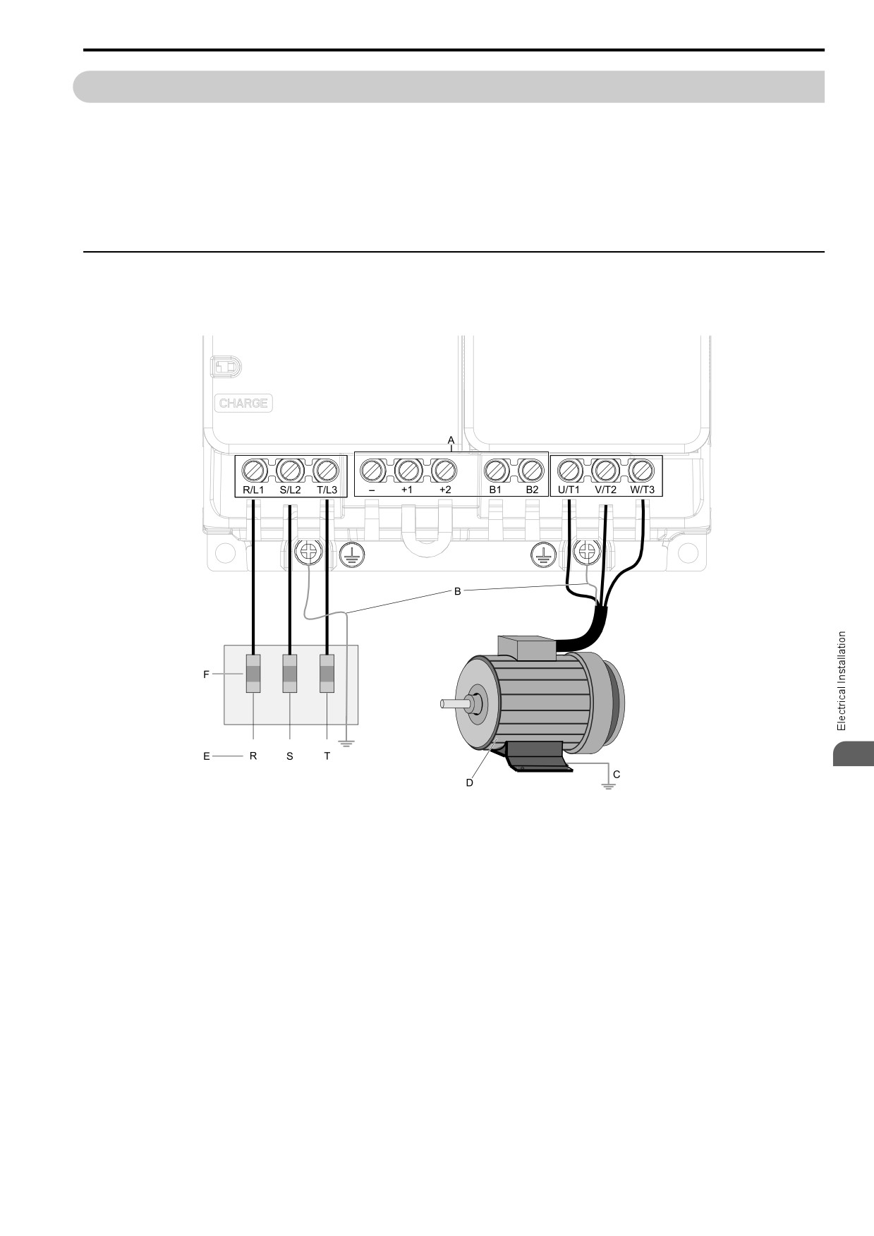
3.3 Main Circuit Wiring
3.3
Main Circuit Wiring
This section gives
information about the functions, specifications, and procedures necessary to safely and
correctly wire the main circuit in the drive.
NOTICE: The drive can fail if users frequently turn the drive ON and OFF with the MC on the power source
side to Run and
Stop the drive. Incorrect operation can decrease the service life of the
relay contacts and electrolytic capacitors. If you
frequently use the magnetic contactor on the power source side to Run and Stop
the drive, it can cause drive failure.
Note:
Soldered wire connections can become loose over time and cause unsatisfactory drive
performance.
◆ Motor and
Main Circuit Connections
WARNING! Electrical
Shock Hazard. Do not connect terminals R/L1, S/L2, T/L3, L/L1, N/L2, U/T1,
V/T2, W/T3, -, +1, +2, B1, or
B2 to the ground terminal. If you connect these terminals to earth ground, it can cause damage to the drive
or serious injury or
death.
3
Note:
The locations of terminals are different for different drive models.
A - DC bus terminal
D - Three-Phase Motor
B - Connect to the drive ground terminal.
E - Use terminals R/L1, S/L2, and T/L3 for three-
phase power supply input. Use terminals L/L1
C - Ground the motor case.
and N/L2 for single-phase power supply input.
F - Input Protection (Fuses or Circuit Breakers)
Figure 3.2 Wiring the Main Circuit and Motor
45
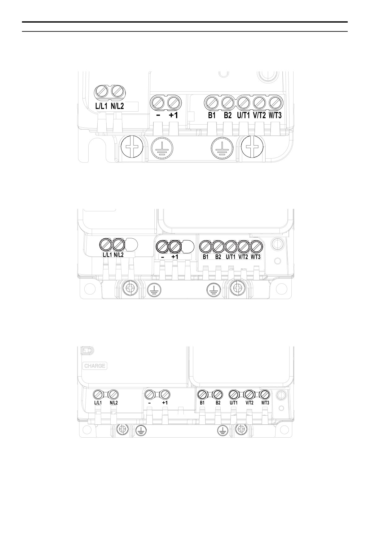
3.3 Main Circuit Wiring
◆ Configuration of Main Circuit Terminal Block
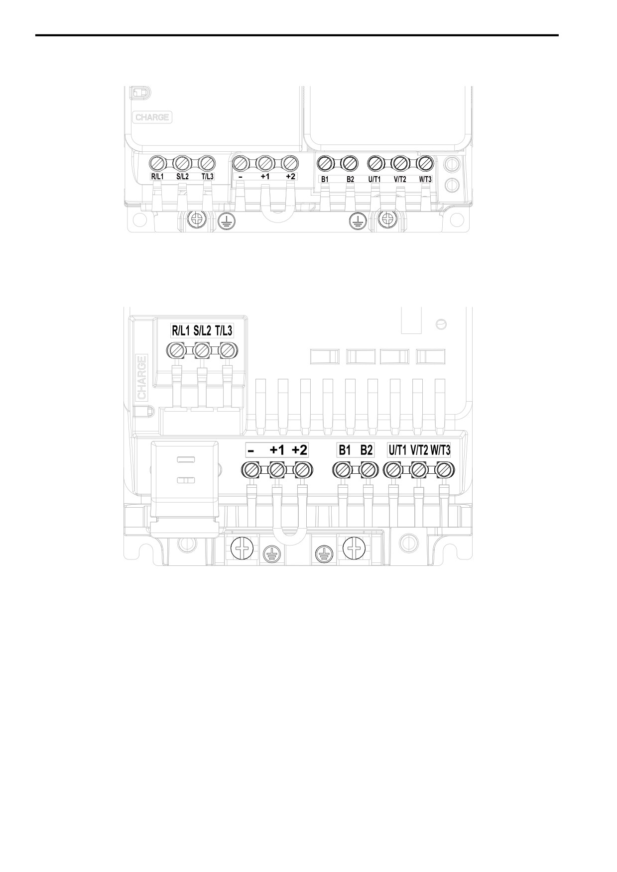
■ Models B001
-
B004
Figure 3.3 Single-Phase, With a Built-in EMC Filter
■ Models B006
-
B010
Figure 3.4 Single-Phase,
With a Built-in EMC Filter
■ Model B012
Figure 3.5 Single-Phase, With a Built-in EMC Filter
46
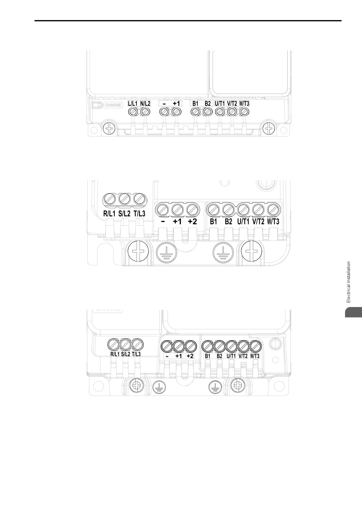
3.3
Main Circuit Wiring
■ Model B018
Figure 3.6 Single-Phase, Without a Built-in EMC Filter
■ Models 2001
-
2006
Figure 3.7 Three-Phase, With a Built-in EMC Filter
■ Models 2008
-
2012, 4001 - 4009
3
Figure 3.8 Three-Phase, With a Built-in EMC Filter
47
3.3 Main Circuit Wiring
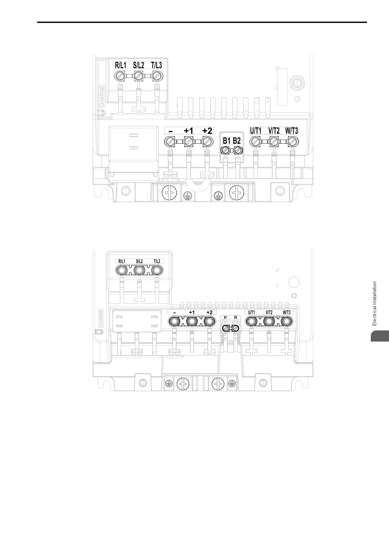
■ Model 2018
-
2021, 4012
Figure 3.9 Three-Phase, With a Built-in EMC Filter
■ Models 2030
-
2042, 4018 - 4023
Figure 3.10 Three-Phase, With a Built-in EMC Filter
48
3.3
Main Circuit Wiring
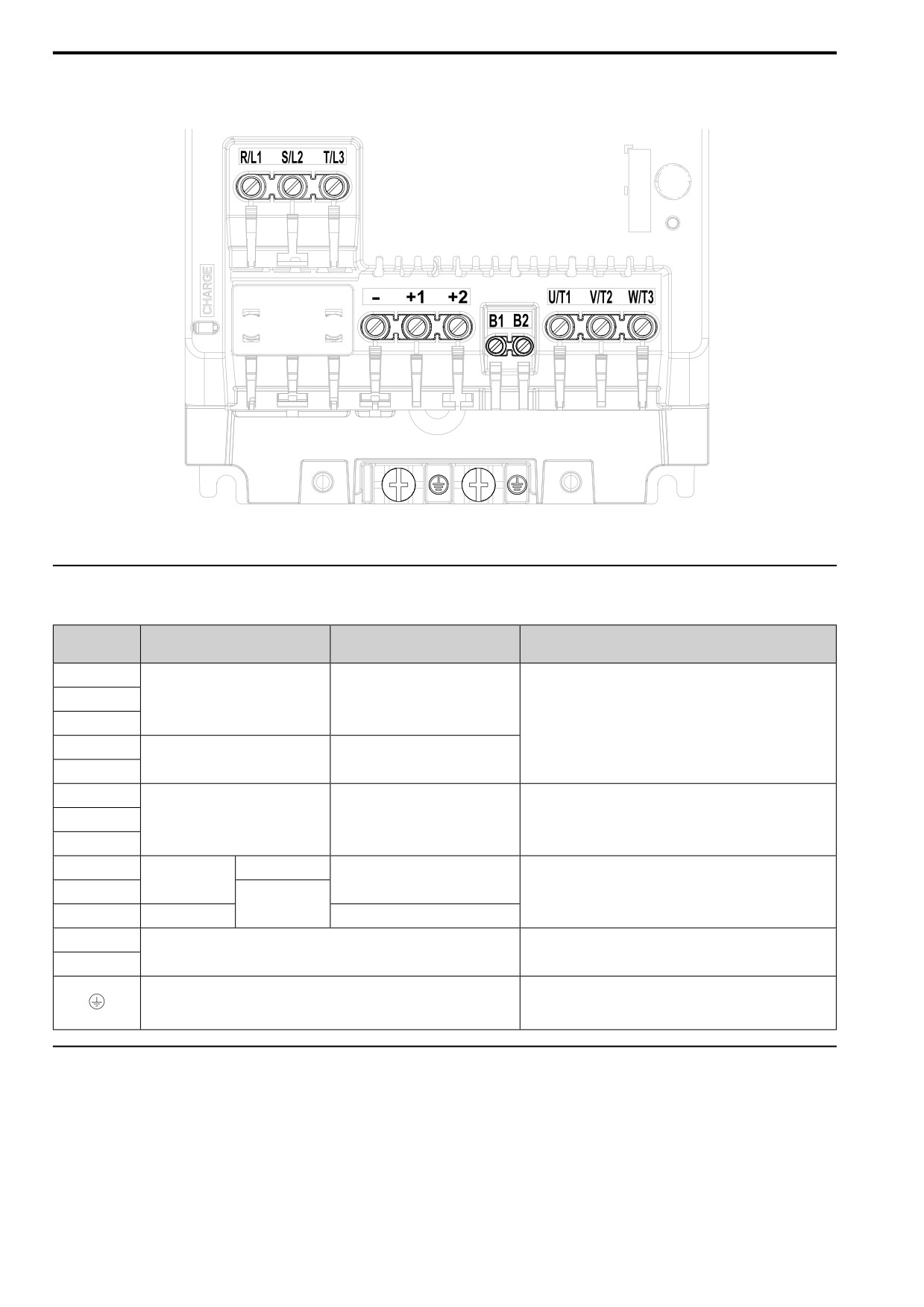
■ Models 2056,
4031 - 4038
Figure 3.11 Three-Phase, With a Built-in EMC Filter
■ Models 2070,
2082
3
Figure 3.12 Three-Phase, With a Built-in EMC Filter
49
3.3 Main Circuit Wiring
■ Models 4044,
4060
Figure 3.13 Three-Phase, With a Built-in EMC Filter
◆ Main Circuit Terminal Functions
Table 3.1 Main Circuit Terminal Names and Functions
Models 2001 - 2082
Terminal
Models B001 - B018
Function
Models 4001 - 4060
R/L1
S/L2
Main circuit power supply input
-
T/L3
To connect a commercial power supply.
L/L1
-
Main circuit power supply input
N/L2
U/T1
V/T2
Drive output
Drive output
To connect a motor.
W/T3
-
-
+1 and +2: To connect a DC reactor.
DC power input
DC power input
+1
Note:
DC reactor
Remove the jumper between terminals +1 and +2 to connect a DC
connection
reactor.
+2
-
-
B1
Braking resistor connection
To connect a braking resistor or braking resistor unit.
B2
To ground the drive.
Ground Wiring
•
200 V: D class grounding (ground to 100 Ω or less)
•
400 V: C class grounding (ground to 10 Ω or less)
◆ Wire Selection
Select the correct wires for main circuit wiring.
Refer to Main Circuit Wire Gauges and Tightening Torques (CE-compliance) on page 149 for wire gauges and
tightening torques as specified by European standards.
Refer to Main Circuit Wire Gauges and Tightening Torques (UL Compliance) on page 167 for wire gauges and
tightening torques as specified by UL standards.
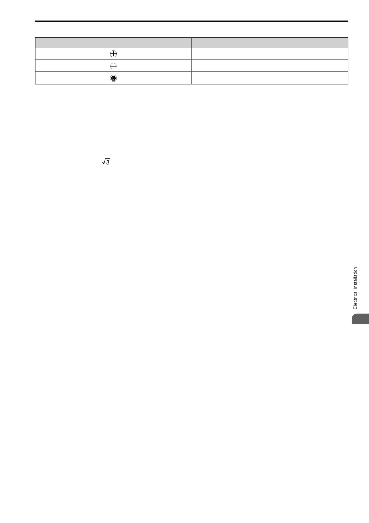
These tables use icons in Table 3.2 to show the shapes of the screw heads.
50
3.3 Main Circuit Wiring
Table 3.2 Icons to Identify Screw Shapes
Icon
Screw Shape
+/-
Slotted (-)
Hex socket cap (WAF: 5 mm)
■ Wire Selection Precautions
WARNING! Electrical Shock Hazard. Make sure that the protective ground wire conforms to technical standards and local
safety regulations. The IEC/EN 61800-5-1:2007 standard specifies that you must wire the power supply to automatically de-
energize when the protective ground wire disconnects. If you turn on the internal EMC filter, the leakage current of the drive will
be more than 3.5 mA. You can also connect a protective ground wire that has a minimum cross-sectional area of 10 mm2
(copper wire). If you do not obey the standards and regulations, it can cause serious injury or death.
Think about line voltage drop before selecting wire gauges. Select wire gauges that drop the voltage by 2% or less
of the rated voltage. Increase the wire gauge and the cable length when the risk of voltage drops increases.
Calculate line voltage drop with this formula:
Line voltage drop (V) =
× wire resistance (Ω/km) × wiring distance (m) × motor rated current (A) × 10-3.
■ Precautions during Wiring
• Refer to “AC Drive Option Braking Unit, Braking Resistor Unit Instruction Manual (TOBPC72060001)” for
information about wire gauges and tightening torques to connect braking resistor units.
• Use terminals +1 and - to connect a regenerative converter or regenerative unit.
WARNING! Fire Hazard. Do not connect a braking resistor to terminals +1 or -. Use terminals B1 and B2 for the braking resistor
connections. If you connect a braking resistor to the incorrect terminals, it can cause damage to the drive and braking circuit and
serious injury or death.
■ Main Circuit Wire Gauges and Tightening Torques for CE Compliance
WARNING! Electrical Shock Hazard. Make sure that the protective ground wire conforms to technical standards and local
safety regulations. The IEC/EN 61800-5-1:2007 standard specifies that you must wire the power supply to automatically de-
energize when the protective ground wire disconnects. If you turn on the internal EMC filter, the leakage current of the drive will
be more than 3.5 mA. You can also connect a protective ground wire that has a minimum cross-sectional area of 10 mm2
(copper wire). If you do not obey the standards and regulations, it can cause serious injury or death.
Note:
• The recommended wire gauges are based on drive continuous current ratings with 75 °C (167 °F) 600 V class 2 heat-resistant indoor
PVC wire. Assume these conditions:
-Ambient temperature: 40 °C (104 °F) maximum
-Wiring distance: 100 m (3281 ft) maximum
-Normal duty rated current value
3
• Use terminals +1, +2, -, B1, and B2 to connect peripheral options, for example a DC reactor or a braking resistor. Do not connect other
items to these terminals.
• Refer to the instruction manual for each device for recommended wire gauges to connect peripheral devices or options to terminals +1,
+2, -, B1, and B2. Contact the manufacturer or your nearest sales representative if the recommended wire gauges for the peripheral
devices or options are out of the range of the applicable gauges for the drive.
51
3.3 Main Circuit Wiring
Three-Phase 200 V Class (CE-compliance)
Wire Stripping
Recommended Gauge
Applicable Gauge
Tightening Torque
Model
Terminal
Length *1
Terminal Screw
mm2
mm2
N∙m (in∙lb)
mm
0.5
- 0.6
R/L1, S/L2, T/L3
2.5
2.5
6.5
M3
(4.4
- 5.3)
0.5
- 0.6
U/T1, V/T2, W/T3
2.5
2.5
6.5
M3
(4.4
- 5.3)
0.5
- 0.6
2001
-, +1, +2
2.5
2.5
6.5
M3
(4.4
- 5.3)
0.5
- 0.6
B1, B2
2.5
2.5
6.5
M3
(4.4
- 5.3)
0.8
- 1.0
2.5 *2
2.5 *2
-
M3.5
(7.1
- 8.9)
0.5
- 0.6
R/L1, S/L2, T/L3
2.5
2.5
6.5
M3
(4.4
- 5.3)
0.5
- 0.6
U/T1, V/T2, W/T3
2.5
2.5
6.5
M3
(4.4
- 5.3)
0.5
- 0.6
2002
-, +1, +2
2.5
2.5
6.5
M3
(4.4
- 5.3)
0.5
- 0.6
B1, B2
2.5
2.5
6.5
M3
(4.4
- 5.3)
0.8
- 1.0
2.5 *2
2.5 *2
-
M3.5
(7.1
- 8.9)
0.5
- 0.6
R/L1, S/L2, T/L3
2.5
2.5
6.5
M3
(4.4
- 5.3)
0.5
- 0.6
U/T1, V/T2, W/T3
2.5
2.5
6.5
M3
(4.4
- 5.3)
0.5
- 0.6
2004
-, +1, +2
2.5
2.5
6.5
M3
(4.4
- 5.3)
0.5
- 0.6
B1, B2
2.5
2.5
6.5
M3
(4.4
- 5.3)
0.8
- 1.0
2.5 *2
2.5 *2
-
M3.5
(7.1
- 8.9)
0.5
- 0.6
R/L1, S/L2, T/L3
2.5
2.5
6.5
M3
(4.4
- 5.3)
0.5
- 0.6
U/T1, V/T2, W/T3
2.5
2.5
6.5
M3
(4.4
- 5.3)
0.5
- 0.6
2006
-, +1, +2
2.5
2.5
6.5
M3
(4.4
- 5.3)
0.5
- 0.6
B1, B2
2.5
2.5
6.5
M3
(4.4
- 5.3)
0.8
- 1.0
2.5 *2
2.5 *2
-
M3.5
(7.1
- 8.9)
0.5
- 0.6
R/L1, S/L2, T/L3
2.5
2.5 - 4
8
M3
(4.4
- 5.3)
0.5
- 0.6
U/T1, V/T2, W/T3
2.5
2.5 - 4
8
M3
(4.4
- 5.3)
0.5
- 0.6
2008
-, +1, +2
2.5
2.5 - 4
8
M3
(4.4
- 5.3)
0.5
- 0.6
B1, B2
2.5
2.5 - 4
8
M3
(4.4
- 5.3)
1.2
- 1.5
4 *2
2.5 - 6 *2
-
M4
(10.6
- 13.3)
52
3.3
Main Circuit Wiring
Wire Stripping
Recommended Gauge
Applicable Gauge
Tightening Torque
Model
Terminal
Length *1
Terminal Screw
mm2
mm2
N∙m (in∙lb)
mm
0.5
- 0.6
R/L1, S/L2, T/L3
2.5
2.5 - 4
8
M3
(4.4
- 5.3)
0.5
- 0.6
U/T1, V/T2, W/T3
2.5
2.5 - 4
8
M3
(4.4
- 5.3)
0.5
- 0.6
2010
-, +1, +2
2.5
2.5 - 4
8
M3
(4.4
- 5.3)
0.5
- 0.6
B1, B2
2.5
2.5 - 4
8
M3
(4.4
- 5.3)
1.2
- 1.5
4 *2
2.5 - 6 *2
-
M4
(10.6
- 13.3)
0.5
- 0.6
R/L1, S/L2, T/L3
2.5
2.5 - 4
8
M3
(4.4
- 5.3)
0.5
- 0.6
U/T1, V/T2, W/T3
2.5
2.5 - 4
8
M3
(4.4
- 5.3)
0.5
- 0.6
2012
-, +1, +2
2.5
2.5 - 4
8
M3
(4.4
- 5.3)
0.5
- 0.6
B1, B2
2.5
2.5 - 4
8
M3
(4.4
- 5.3)
1.2
- 1.5
4 *2
2.5 - 6 *2
-
M4
(10.6
- 13.3)
1.5
- 1.7
R/L1, S/L2, T/L3
2.5
2.5 - 4
10
M4
(13.5 - 15)
1.5
- 1.7
U/T1, V/T2, W/T3
2.5
2.5 - 4
10
M4
(13.5 - 15)
1.5
- 1.7
2018
-, +1, +2
4
2.5 - 6
10
M4
(13.5 - 15)
1.5
- 1.7
B1, B2
2.5
2.5 - 4
10
M4
(13.5 - 15)
1.2
- 1.5
6 *2
2.5 - 6 *2
-
M4
(10.6
- 13.3)
1.5
- 1.7
R/L1, S/L2, T/L3
4
2.5 - 6
10
M4
(13.5 - 15)
1.5
- 1.7
U/T1, V/T2, W/T3
2.5
2.5 - 4
10
M4
(13.5 - 15)
1.5
- 1.7
2021
-, +1, +2
6
4 - 10
10
M4
(13.5 - 15)
3
1.5
- 1.7
B1, B2
2.5
2.5 - 4
10
M4
(13.5 - 15)
1.2
- 1.5
6 *2
2.5 - 6 *2
-
M4
(10.6
- 13.3)
1.5
- 1.7
R/L1, S/L2, T/L3
6
4 - 10
10
M4
(13.5 - 15)
1.5
- 1.7
U/T1, V/T2, W/T3
6
4 - 10
10
M4
(13.5 - 15)
1.5
- 1.7
2030
-, +1, +2
10
2.5 - 16
10
M4
(13.5 - 15)
1.5
- 1.7
B1, B2
2.5
2.5 - 4
10
M4
(13.5 - 15)
2.0
- 2.5
6 *2
6 - 16
-
M5
(17.7
- 22.1)
53
3.3 Main Circuit Wiring
Wire Stripping
Recommended Gauge
Applicable Gauge
Tightening Torque
Model
Terminal
Length *1
Terminal Screw
mm2
mm2
N∙m (in∙lb)
mm
1.5
- 1.7
R/L1, S/L2, T/L3
10
2.5 - 16
10
M4
(13.5 - 15)
1.5
- 1.7
U/T1, V/T2, W/T3
10
2.5 - 16
10
M4
(13.5 - 15)
2.3
- 2.5
2042
-, +1, +2
16
4 - 25
18
M5
(19.8 - 22)
1.5
- 1.7
B1, B2
4
2.5 - 6
10
M4
(13.5 - 15)
2.0
- 2.5
10
6 - 16
-
M5
(17.7
- 22.1)
2.3
- 2.5
R/L1, S/L2, T/L3
16
4 - 25
18
M5
(19.8 - 22)
2.3
- 2.5
U/T1, V/T2, W/T3
16
4 - 25
18
M5
(19.8 - 22)
•
≤ 25 mm2
2.3
- 2.5
(19.8 - 22)
2056
-, +1, +2
25
6 - 35
18
M5
•
35 mm2 ≤
4.1
- 4.5
(36 - 40)
1.5
- 1.7
B1, B2
10
4 - 16
10
M4
(13.5 - 15)
5.4
- 6.0
10
10 - 25
-
M6
(47.8
- 53.1)
5 - 5.5
R/L1, S/L2, T/L3
25
6 - 35
20
M6
(45 - 49)
5 - 5.5
U/T1, V/T2, W/T3
16
6 - 25
20
M6
(45 - 49)
5 - 5.5
2070
-, +1, +2
35
10 - 50
20
M6
(45 - 49)
1.5
- 1.7
B1, B2
10
4 - 16
10
M4
(13.5 - 15)
5.4
- 6.0
16
10 - 25
-
M6
(47.8
- 53.1)
5 - 5.5
R/L1, S/L2, T/L3
35
10 - 50
20
M6
(45 - 49)
5 - 5.5
U/T1, V/T2, W/T3
25
10 - 35
20
M6
(45 - 49)
5 - 5.5
2082
-, +1, +2
50
16 - 70
20
M6
(45 - 49)
1.5
- 1.7
B1, B2
16
4 - 16
10
M4
(13.5 - 15)
5.4
- 6.0
16
10 - 25
-
M6
(47.8
- 53.1)
*1
Remove insulation from the ends of wires to expose the length of wire shown.
*2
If you turn on the internal EMC filter, the leakage current of the drive will be more than 3.5 mA. Use these closed-loop crimp
terminals or equivalent to connect a protective ground wire that has a minimum cross-sectional area of 10 mm2 (copper wire).
•
8-4NS from JST Mfg. Co., Ltd.
• R8-4S from NICHIFU Co.,Ltd.
54
3.3
Main Circuit Wiring
Single-Phase 200 V Class (CE-compliance)
Wire Stripping
Recommended Gauge
Applicable Gauge
Tightening Torque
Model
Terminal
Length *1
Terminal Screw
mm2
mm2
N∙m (in∙lb)
mm
0.5
- 0.6
L/L1, N/L2
2.5
2.5
6.5
M3
(4.4
- 5.3)
0.5
- 0.6
U/T1, V/T2, W/T3
2.5
2.5
6.5
M3
(4.4
- 5.3)
0.5
- 0.6
B001
-, +1
2.5
2.5
6.5
M3
(4.4
- 5.3)
0.5
- 0.6
B1, B2
2.5
2.5
6.5
M3
(4.4
- 5.3)
0.8
- 1.0
2.5 *2
2.5 *2
-
M3.5
(7.1
- 8.9)
0.5
- 0.6
L/L1, N/L2
2.5
2.5
6.5
M3
(4.4
- 5.3)
0.5
- 0.6
U/T1, V/T2, W/T3
2.5
2.5
6.5
M3
(4.4
- 5.3)
0.5
- 0.6
B002
-, +1
2.5
2.5
6.5
M3
(4.4
- 5.3)
0.5
- 0.6
B1, B2
2.5
2.5
6.5
M3
(4.4
- 5.3)
0.8
- 1.0
2.5 *2
2.5 *2
-
M3.5
(7.1
- 8.9)
0.5
- 0.6
L/L1, N/L2
2.5
2.5
6.5
M3
(4.4
- 5.3)
0.5
- 0.6
U/T1, V/T2, W/T3
2.5
2.5
6.5
M3
(4.4
- 5.3)
0.5
- 0.6
B004
-, +1
2.5
2.5
6.5
M3
(4.4
- 5.3)
0.5
- 0.6
B1, B2
2.5
2.5
6.5
M3
(4.4
- 5.3)
0.8
- 1.0
2.5 *2
2.5 *2
-
M3.5
(7.1
- 8.9)
0.5
- 0.6
L/L1, N/L2
2.5
2.5 - 4
8
M3
(4.4
- 5.3)
0.5
- 0.6
U/T1, V/T2, W/T3
2.5
2.5 - 4
8
M3
(4.4
- 5.3)
3
0.5
- 0.6
B006
-, +1
2.5
2.5 - 4
8
M3
(4.4
- 5.3)
0.5
- 0.6
B1, B2
2.5
2.5 - 4
8
M3
(4.4
- 5.3)
1.2
- 1.5
2.5 *2
2.5 - 6 *2
-
M4
(10.6
- 13.3)
0.5
- 0.6
L/L1, N/L2
2.5
2.5 - 4
8
M3
(4.4
- 5.3)
0.5
- 0.6
U/T1, V/T2, W/T3
2.5
2.5 - 4
8
M3
(4.4
- 5.3)
0.5
- 0.6
B010
-, +1
2.5
2.5 - 4
8
M3
(4.4
- 5.3)
0.5
- 0.6
B1, B2
2.5
2.5 - 4
8
M3
(4.4
- 5.3)
1.2
- 1.5
2.5 *2
2.5 - 6 *2
-
M4
(10.6
- 13.3)
55
3.3 Main Circuit Wiring
Wire Stripping
Recommended Gauge
Applicable Gauge
Tightening Torque
Model
Terminal
Length *1
Terminal Screw
mm2
mm2
N∙m (in∙lb)
mm
1.5
- 1.7
L/L1, N/L2
4
2.5 - 6
10
M4
(13.5 - 15)
1.5
- 1.7
U/T1, V/T2, W/T3
2.5
2.5 - 4
10
M4
(13.5 - 15)
1.5
- 1.7
B012
-, +1
4
2.5 - 6
10
M4
(13.5 - 15)
1.5
- 1.7
B1, B2
2.5
2.5 - 4
10
M4
(13.5 - 15)
1.2
- 1.5
4 *2
2.5 - 6 *2
-
M4
(10.6
- 13.3)
1.5
- 1.7
L/L1, N/L2
6
2.5 - 10
10
M4
(13.5 - 15)
1.5
- 1.7
U/T1, V/T2, W/T3
2.5
2.5 - 4
10
M4
(13.5 - 15)
1.5
- 1.7
B018
-, +1
6
2.5 - 10
10
M4
(13.5 - 15)
1.5
- 1.7
B1, B2
2.5
2.5 - 4
10
M4
(13.5 - 15)
2.0
- 2.5
6 *2
4 - 10 *2
-
M5
(17.7
- 22.1)
*1
Remove insulation from the ends of wires to expose the length of wire shown.
*2
If you turn on the internal EMC filter, the leakage current of the drive will be more than 3.5 mA. Use these closed-loop crimp
terminals or equivalent to connect a protective ground wire that has a minimum cross-sectional area of 10 mm2 (copper wire).
•
8-4NS from JST Mfg. Co., Ltd.
• R8-4S from NICHIFU Co.,Ltd.
Three-Phase 400 V Class (CE-compliance)
Wire Stripping
Recommended Gauge
Applicable Gauge
Tightening Torque
Model
Terminal
Length *1
Terminal Screw
mm2
mm2
N∙m (in∙lb)
mm
0.5
- 0.6
R/L1, S/L2, T/L3
2.5
2.5 - 4
8
M3
(4.4
- 5.3)
0.5
- 0.6
U/T1, V/T2, W/T3
2.5
2.5 - 4
8
M3
(4.4
- 5.3)
0.5
- 0.6
4001
-, +1, +2
2.5
2.5 - 4
8
M3
(4.4
- 5.3)
0.5
- 0.6
B1, B2
2.5
2.5 - 4
8
M3
(4.4
- 5.3)
1.2
- 1.5
2.5 *2
2.5 - 6 *2
-
M4
(10.6
- 13.3)
0.5
- 0.6
R/L1, S/L2, T/L3
2.5
2.5 - 4
8
M3
(4.4
- 5.3)
0.5
- 0.6
U/T1, V/T2, W/T3
2.5
2.5 - 4
8
M3
(4.4
- 5.3)
0.5
- 0.6
4002
-, +1, +2
2.5
2.5 - 4
8
M3
(4.4
- 5.3)
0.5
- 0.6
B1, B2
2.5
2.5 - 4
8
M3
(4.4
- 5.3)
1.2
- 1.5
2.5 *2
2.5 - 6 *2
-
M4
(10.6
- 13.3)
56
3.3
Main Circuit Wiring
Wire Stripping
Recommended Gauge
Applicable Gauge
Tightening Torque
Model
Terminal
Length *1
Terminal Screw
mm2
mm2
N∙m (in∙lb)
mm
0.5
- 0.6
R/L1, S/L2, T/L3
2.5
2.5 - 4
8
M3
(4.4
- 5.3)
0.5
- 0.6
U/T1, V/T2, W/T3
2.5
2.5 - 4
8
M3
(4.4
- 5.3)
0.5
- 0.6
4004
-, +1, +2
2.5
2.5 - 4
8
M3
(4.4
- 5.3)
0.5
- 0.6
B1, B2
2.5
2.5 - 4
8
M3
(4.4
- 5.3)
1.2
- 1.5
4 *2
2.5 - 6 *2
-
M4
(10.6
- 13.3)
0.5
- 0.6
R/L1, S/L2, T/L3
2.5
2.5 - 4
8
M3
(4.4
- 5.3)
0.5
- 0.6
U/T1, V/T2, W/T3
2.5
2.5 - 4
8
M3
(4.4
- 5.3)
0.5
- 0.6
4005
-, +1, +2
2.5
2.5 - 4
8
M3
(4.4
- 5.3)
0.5
- 0.6
B1, B2
2.5
2.5 - 4
8
M3
(4.4
- 5.3)
1.2
- 1.5
4 *2
2.5 - 6 *2
-
M4
(10.6
- 13.3)
0.5
- 0.6
R/L1, S/L2, T/L3
2.5
2.5 - 4
8
M3
(4.4
- 5.3)
0.5
- 0.6
U/T1, V/T2, W/T3
2.5
2.5 - 4
8
M3
(4.4
- 5.3)
0.5
- 0.6
4007
-, +1, +2
2.5
2.5 - 4
8
M3
(4.4
- 5.3)
0.5
- 0.6
B1, B2
2.5
2.5 - 4
8
M3
(4.4
- 5.3)
1.2
- 1.5
4 *2
2.5 - 6 *2
-
M4
(10.6
- 13.3)
0.5
- 0.6
R/L1, S/L2, T/L3
2.5
2.5 - 4
8
M3
(4.4
- 5.3)
0.5
- 0.6
U/T1, V/T2, W/T3
2.5
2.5 - 4
8
M3
(4.4
- 5.3)
0.5
- 0.6
4009
-, +1, +2
2.5
2.5 - 4
8
M3
(4.4
- 5.3)
3
0.5
- 0.6
B1, B2
2.5
2.5 - 4
8
M3
(4.4
- 5.3)
1.2
- 1.5
4 *2
2.5 - 6 *2
-
M4
(10.6
- 13.3)
1.5
- 1.7
R/L1, S/L2, T/L3
2.5
2.5 - 4
10
M4
(13.5 - 15)
1.5
- 1.7
U/T1, V/T2, W/T3
2.5
2.5 - 4
10
M4
(13.5 - 15)
1.5
- 1.7
4012
-, +1, +2
2.5
2.5 - 4
10
M4
(13.5 - 15)
1.5
- 1.7
B1, B2
2.5
2.5 - 4
10
M4
(13.5 - 15)
1.2
- 1.5
4 *2
2.5 - 6 *2
-
M4
(10.6
- 13.3)
57
3.3 Main Circuit Wiring
Wire Stripping
Recommended Gauge
Applicable Gauge
Tightening Torque
Model
Terminal
Length *1
Terminal Screw
mm2
mm2
N∙m (in∙lb)
mm
1.5
- 1.7
R/L1, S/L2, T/L3
2.5
2.5 - 4
10
M4
(13.5 - 15)
1.5
- 1.7
U/T1, V/T2, W/T3
2.5
2.5 - 4
10
M4
(13.5 - 15)
1.5
- 1.7
4018
-, +1, +2
4
2.5 - 6
10
M4
(13.5 - 15)
1.5
- 1.7
B1, B2
2.5
2.5 - 4
10
M4
(13.5 - 15)
2.0
- 2.5
4 *2
2.5 - 16
-
M5
(17.7
- 22.1)
1.5
- 1.7
R/L1, S/L2, T/L3
4
2.5 - 6
10
M4
(13.5 - 15)
1.5
- 1.7
U/T1, V/T2, W/T3
4
2.5 - 6
10
M4
(13.5 - 15)
1.5
- 1.7
4023
-, +1, +2
4
4-6
10
M4
(13.5 - 15)
1.5
- 1.7
B1, B2
2.5
2.5 - 4
10
M4
(13.5 - 15)
2.0
- 2.5
4 *2
4 - 16
-
M5
(17.7
- 22.1)
1.5
- 1.7
R/L1, S/L2, T/L3
6
4 - 10
10
M4
(13.5 - 15)
1.5
- 1.7
U/T1, V/T2, W/T3
6
4 - 10
10
M4
(13.5 - 15)
2.3
- 2.5
4031
-, +1, +2
10
2.5 - 16
18
M5
(19.8 - 22)
1.5
- 1.7
B1, B2
2.5
2.5 - 4
10
M4
(13.5 - 15)
5.4
- 6.0
6 *2
6 - 16 *2
-
M6
(47.8
- 53.1)
1.5
- 1.7
R/L1, S/L2, T/L3
10
4 - 16
10
M4
(13.5 - 15)
1.5
- 1.7
U/T1, V/T2, W/T3
6
2.5 - 10
10
M4
(13.5 - 15)
2.3
- 2.5
4038
-, +1, +2
16
4 - 25
18
M5
(19.8 - 22)
1.5
- 1.7
B1, B2
4
2.5 - 6
10
M4
(13.5 - 15)
5.4
- 6.0
10
6 - 16
-
M6
(47.8
- 53.1)
2.3
- 2.5
R/L1, S/L2, T/L3
16
4 - 25
18
M5
(19.8 - 22)
2.3
- 2.5
U/T1, V/T2, W/T3
10
4 - 16
18
M5
(19.8 - 22)
2.3
- 2.5
4044
-, +1, +2
16
6 - 25
18
M5
(19.8 - 22)
1.5
- 1.7
B1, B2
6
4 - 10
10
M4
(13.5 - 15)
5.4
- 6.0
10
6 - 16
-
M6
(47.8
- 53.1)
58
3.3 Main Circuit Wiring
Wire Stripping
Recommended Gauge
Applicable Gauge
Tightening Torque
Model
Terminal
Length *1
Terminal Screw
mm2
mm2
N∙m (in∙lb)
mm
•
≤ 25 mm2
2.3
- 2.5
(19.8 - 22)
R/L1, S/L2, T/L3
25
6 - 35
18
M5
•
35 mm2 ≤
4.1
- 4.5
(36 - 40)
2.3
- 2.5
U/T1, V/T2, W/T3
16
4 - 25
18
M5
(19.8 - 22)
•
≤ 25 mm
2
4060
2.3
- 2.5
(19.8 - 22)
-, +1, +2
25
6 - 35
18
M5
•
35 mm2 ≤
4.1
- 4.5
(36 - 40)
1.5
- 1.7
B1, B2
10
2.5 - 16
10
M4
(13.5 - 15)
5.4
- 6.0
10
6 - 16
-
M6
(47.8
- 53.1)
*1
Remove insulation from the ends of wires to expose the length of wire shown.
*2
If you turn on the internal EMC filter, the leakage current of the drive will be more than 3.5 mA. Use these closed-loop crimp
terminals or equivalent to connect a protective ground wire that has a minimum cross-sectional area of 10 mm2 (copper wire).
•
8-4NS from JST Mfg. Co., Ltd.
• R8-4S from NICHIFU Co.,Ltd.
■ Main Circuit Wire Gauges and Tightening Torques for UL Compliance
WARNING! Electrical Shock Hazard. Make sure that the protective ground wire conforms to technical standards and local
safety regulations. The IEC/EN 61800-5-1:2007 standard specifies that you must wire the power supply to automatically de-
energize when the protective ground wire disconnects. If you turn on the internal EMC filter, the leakage current of the drive will
be more than 3.5 mA. You can also connect a protective ground wire that has a minimum cross-sectional area of 10 mm2
(copper wire). If you do not obey the standards and regulations, it can cause serious injury or death.
Note:
• The recommended wire gauges are based on drive continuous current ratings with 75 °C (167 °F) 600 V class 2 heat-resistant indoor
PVC wire. Assume these conditions:
-Ambient temperature: 40 °C (104 °F) maximum
-Wiring distance: 100 m (3281 ft) maximum
-Normal duty rated current value
• Use terminals +1, +2, -, B1, and B2 to connect peripheral options, for example a DC reactor or a braking resistor. Do not connect other
items to these terminals.
• Refer to the instruction manual for each device for recommended wire gauges to connect peripheral devices or options to terminals +1,
+2, -, B1, and B2. Contact the manufacturer or your nearest sales representative if the recommended wire gauges for the peripheral
devices or options are out of the range of the applicable gauges for the drive.
3
59
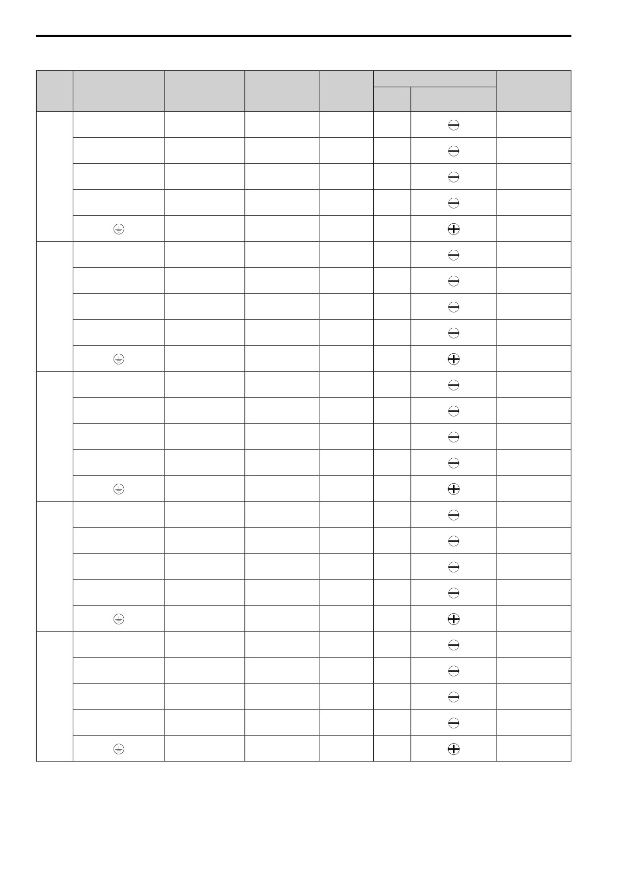
3.3 Main Circuit Wiring
Three-Phase 200 V Class (UL-compliance)
Wire
Terminal Screw
Recommended
Applicable Gauge
Stripping
Tightening Torque
Model
Terminal
Gauge
Length *1
mm2
mm2
Size
Shape
N∙m (in∙lb)
mm
0.5
- 0.6
R/L1, S/L2, T/L3
2
2
6.5
M3
(4.4
- 5.3)
0.5
- 0.6
U/T1, V/T2, W/T3
2
2
6.5
M3
(4.4
- 5.3)
0.5
- 0.6
2001
-, +1, +2
2
2
6.5
M3
(4.4
- 5.3)
0.5
- 0.6
B1, B2
2
2
6.5
M3
(4.4
- 5.3)
0.8
- 1.0
2 *2
2 *2
-
M3.5
(7.1
- 8.9)
0.5
- 0.6
R/L1, S/L2, T/L3
2
2
6.5
M3
(4.4
- 5.3)
0.5
- 0.6
U/T1, V/T2, W/T3
2
2
6.5
M3
(4.4
- 5.3)
0.5
- 0.6
2002
-, +1, +2
2
2
6.5
M3
(4.4
- 5.3)
0.5
- 0.6
B1, B2
2
2
6.5
M3
(4.4
- 5.3)
0.8
- 1.0
2 *2
2 *2
-
M3.5
(7.1
- 8.9)
0.5 -
0.6
R/L1, S/L2, T/L3
2
2
6.5
M3
(4.4 -
5.3)
0.5 -
0.6
U/T1, V/T2, W/T3
2
2
6.5
M3
(4.4 -
5.3)
0.5 -
0.6
2004
-, +1, +2
2
2
6.5
M3
(4.4 -
5.3)
0.5 -
0.6
B1, B2
2
2
6.5
M3
(4.4 -
5.3)
0.8 -
1.0
2 *2
2 *2
-
M3.5
(7.1 -
8.9)
0.5 -
0.6
R/L1, S/L2, T/L3
2
2
6.5
M3
(4.4 -
5.3)
0.5 -
0.6
U/T1, V/T2, W/T3
2
2
6.5
M3
(4.4 -
5.3)
0.5 -
0.6
2006
-, +1, +2
2
2
6.5
M3
(4.4 -
5.3)
0.5 -
0.6
B1, B2
2
2
6.5
M3
(4.4 -
5.3)
0.8 -
1.0
2 *2
2 *2
-
M3.5
(7.1 -
8.9)
0.5 -
0.6
R/L1, S/L2, T/L3
2
2 - 3.5
8
M3
(4.4 -
5.3)
0.5 -
0.6
U/T1, V/T2, W/T3
2
2 - 3.5
8
M3
(4.4 -
5.3)
0.5 -
0.6
2008
-, +1, +2
2
2 - 3.5
8
M3
(4.4 -
5.3)
0.5 -
0.6
B1, B2
2
2 - 3.5
8
M3
(4.4 -
5.3)
1.2 -
1.5
3.5 *2
2 - 5.5 *2
-
M4
(10.6 -
13.3)
60
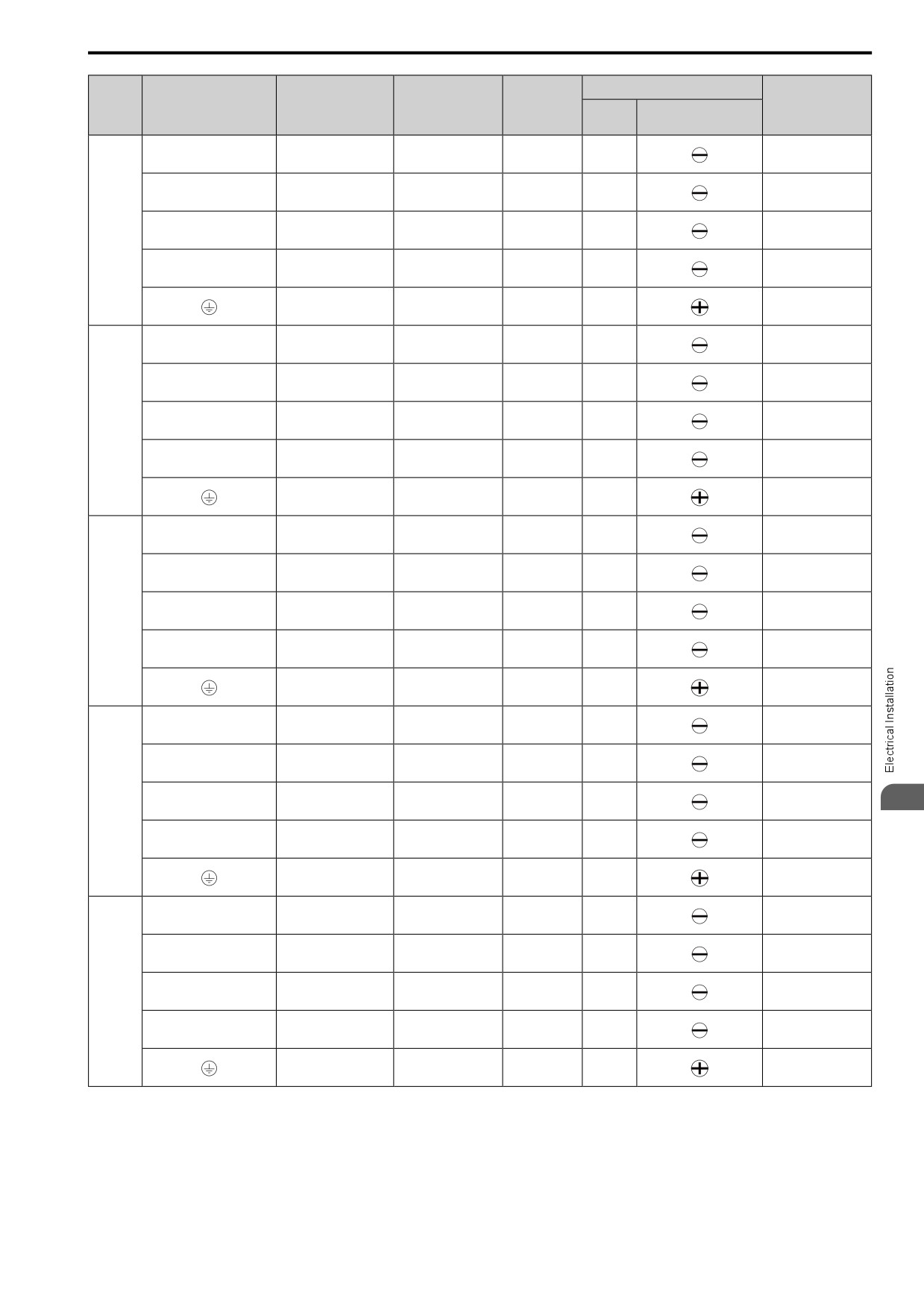
3.3
Main Circuit Wiring
Wire
Terminal Screw
Recommended
Applicable Gauge
Stripping
Tightening Torque
Model
Terminal
Gauge
Length *1
mm2
mm2
Size
Shape
N∙m (in∙lb)
mm
0.5
- 0.6
R/L1, S/L2, T/L3
2
2 - 3.5
8
M3
(4.4
- 5.3)
0.5
- 0.6
U/T1, V/T2, W/T3
2
2 - 3.5
8
M3
(4.4
- 5.3)
0.5
- 0.6
2010
-, +1, +2
2
2 - 3.5
8
M3
(4.4
- 5.3)
0.5
- 0.6
B1, B2
2
2 - 3.5
8
M3
(4.4
- 5.3)
1.2
- 1.5
3.5 *2
2 - 5.5 *2
-
M4
(10.6
- 13.3)
0.5
- 0.6
R/L1, S/L2, T/L3
2
2 - 3.5
8
M3
(4.4
- 5.3)
0.5
- 0.6
U/T1, V/T2, W/T3
2
2 - 3.5
8
M3
(4.4
- 5.3)
0.5
- 0.6
2012
-, +1, +2
3.5
2 - 5.5
8
M3
(4.4
- 5.3)
0.5
- 0.6
B1, B2
2
2 - 3.5
8
M3
(4.4
- 5.3)
1.2
- 1.5
3.5 *2
2 - 5.5 *2
-
M4
(10.6
- 13.3)
1.5
- 1.7
R/L1, S/L2, T/L3
3.5
2 - 5.5
10
M4
(13.5 - 15)
1.5
- 1.7
U/T1, V/T2, W/T3
3.5
2 - 5.5
10
M4
(13.5 - 15)
1.5
- 1.7
2018
-, +1, +2
5.5
3.5 - 8
10
M4
(13.5 - 15)
1.5
- 1.7
B1, B2
2
2 - 3.5
10
M4
(13.5 - 15)
1.2
- 1.5
5.5 *2
2 - 5.5 *2
-
M4
(10.6
- 13.3)
1.5
- 1.7
R/L1, S/L2, T/L3
5.5
3.5 - 8
10
M4
(13.5 - 15)
1.5
- 1.7
U/T1, V/T2, W/T3
3.5
3.5
- 5.5
10
M4
(13.5 - 15)
1.5
- 1.7
2021
-, +1, +2
8
2-8
10
M4
3
(13.5 - 15)
1.5
- 1.7
B1, B2
2
2 - 3.5
10
M4
(13.5 - 15)
1.2
- 1.5
5.5 *2
2 - 5.5 *2
-
M4
(10.6
- 13.3)
1.5
- 1.7
R/L1, S/L2, T/L3
8
2 - 14
10
M4
(13.5 - 15)
1.5
- 1.7
U/T1, V/T2, W/T3
8
2 - 14
10
M4
(13.5 - 15)
1.5
- 1.7
2030
-, +1, +2
14
3.5 - 14
10
M4
(13.5 - 15)
1.5
- 1.7
B1, B2
3.5
2 - 5.5
10
M4
(13.5 - 15)
2.0
- 2.5
5.5 *2
5.5 - 14
-
M5
(17.7
- 22.1)
61
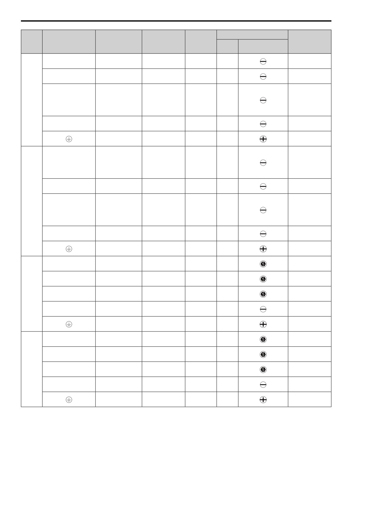
3.3 Main Circuit Wiring
Wire
Terminal Screw
Recommended
Applicable Gauge
Stripping
Tightening Torque
Model
Terminal
Gauge
Length *1
mm2
mm2
Size
Shape
N∙m (in∙lb)
mm
1.5
- 1.7
R/L1, S/L2, T/L3
14
3.5 - 14
10
M4
(13.5 - 15)
1.5
- 1.7
U/T1, V/T2, W/T3
14
3.5 - 14
10
M4
(13.5 - 15)
•
≤ 22 mm2
2.3
- 2.5
(19.8 - 22)
2042
-, +1, +2
22
5.5 - 30
18
M5
•
30 mm2 ≤
4.1
- 4.5
(36 - 40)
1.5
- 1.7
B1, B2
5.5
3.5 - 8
10
M4
(13.5 - 15)
2.0
- 2.5
8 *2
5.5 - 14
-
M5
(17.7
- 22.1)
•
≤ 22 mm2
2.3
- 2.5
(19.8 - 22)
R/L1, S/L2, T/L3
22
5.5 - 30
18
M5
•
30 mm2 ≤
4.1
- 4.5
(36 - 40)
2.3
- 2.5
U/T1, V/T2, W/T3
14
5.5 - 22
18
M5
(19.8 - 22)
•
≤ 22 mm
2
2056
2.3
- 2.5
(19.8 - 22)
-, +1, +2
30
8 - 30
18
M5
•
30 mm2 ≤
4.1
- 4.5
(36 - 40)
1.5
- 1.7
B1, B2
14
2 - 14
10
M4
(13.5 - 15)
5.4
- 6.0
8 *2
8 - 22
-
M6
(47.8
- 53.1)
5 - 5.5
R/L1, S/L2, T/L3
30
8 - 38
20
M6
(45 - 49)
5 - 5.5
U/T1, V/T2, W/T3
22
5.5 - 30
20
M6
(45 - 49)
5 - 5.5
2070
-, +1, +2
38
14 - 50
20
M6
(45 - 49)
1.5
- 1.7
B1, B2
14
5.5 - 14
10
M4
(13.5 - 15)
5.4
- 6.0
14
8 - 22
-
M6
(47.8
- 53.1)
5 - 5.5
R/L1, S/L2, T/L3
38
14 - 50
20
M6
(45 - 49)
5 - 5.5
U/T1, V/T2, W/T3
30
8 - 38
20
M6
(45 - 49)
5 - 5.5
2082
-, +1, +2
50
22 - 60
20
M6
(45 - 49)
1.5
- 1.7
B1, B2
14
5.5 - 14
10
M4
(13.5 - 15)
5.4
- 6.0
14
8 - 22
-
M6
(47.8
- 53.1)
*1
Remove insulation from the ends of wires to expose the length of wire shown.
*2
If you turn on the built-in EMC filter, the leakage current of the drive will be more than 3.5 mA. Use these closed-loop crimp
terminals or equivalent to connect a protective ground wire that has a minimum cross-sectional area of 10 mm2 (copper wire).
•
8-4NS from JST Mfg. Co., Ltd.
• R8-4S from NICHIFU Co.,Ltd.
62
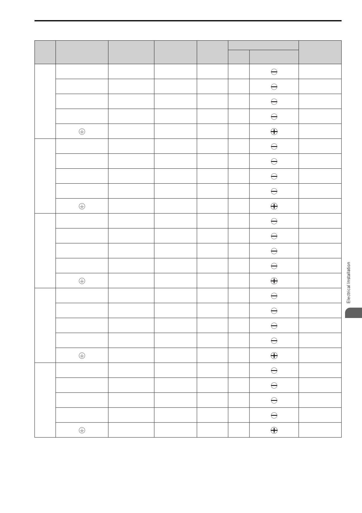
3.3
Main Circuit Wiring
Single-Phase 200 V Class (UL-compliance)
Wire
Terminal Screw
Recommended
Applicable Gauge
Stripping
Tightening Torque
Model
Terminal
Gauge
Length *1
mm2
mm2
Size
Shape
N∙m (in∙lb)
mm
0.5
- 0.6
L/L1, N/L2
2
2
6.5
M3
(4.4
- 5.3)
0.5
- 0.6
U/T1, V/T2, W/T3
2
2
6.5
M3
(4.4
- 5.3)
0.5
- 0.6
B001
-, +1
2
2
6.5
M3
(4.4
- 5.3)
0.5
- 0.6
B1, B2
2
2
6.5
M3
(4.4
- 5.3)
0.8
- 1.0
2 *2
2 *2
-
M3.5
(7.1
- 8.9)
0.5
- 0.6
L/L1, N/L2
2
2
6.5
M3
(4.4
- 5.3)
0.5
- 0.6
U/T1, V/T2, W/T3
2
2
6.5
M3
(4.4
- 5.3)
0.5
- 0.6
B002
-, +1
2
2
6.5
M3
(4.4
- 5.3)
0.5
- 0.6
B1, B2
2
2
6.5
M3
(4.4
- 5.3)
0.8
- 1.0
2 *2
2 *2
-
M3.5
(7.1
- 8.9)
0.5
- 0.6
L/L1, N/L2
2
2
6.5
M3
(4.4
- 5.3)
0.5
- 0.6
U/T1, V/T2, W/T3
2
2
6.5
M3
(4.4
- 5.3)
0.5
- 0.6
B004
-, +1
2
2
6.5
M3
(4.4
- 5.3)
0.5
- 0.6
B1, B2
2
2
6.5
M3
(4.4
- 5.3)
0.8
- 1.0
2 *2
2 *2
-
M3.5
(7.1
- 8.9)
0.5
- 0.6
L/L1, N/L2
2
2 - 3.5
8
M3
(4.4
- 5.3)
0.5
- 0.6
U/T1, V/T2, W/T3
2
2 - 3.5
8
M3
(4.4
- 5.3)
3
0.5
- 0.6
B006
-, +1
2
2 - 3.5
8
M3
(4.4
- 5.3)
0.5
- 0.6
B1, B2
2
2 - 3.5
8
M3
(4.4
- 5.3)
1.2
- 1.5
3.5 *2
2 - 5.5 *2
-
M4
(10.6
- 13.3)
0.5
- 0.6
L/L1, N/L2
3.5
2 - 5.5
8
M3
(4.4
- 5.3)
0.5
- 0.6
U/T1, V/T2, W/T3
2
2 - 3.5
8
M3
(4.4
- 5.3)
0.5
- 0.6
B010
-, +1
3.5
2 - 5.5
8
M3
(4.4
- 5.3)
0.5
- 0.6
B1, B2
2
2 - 3.5
8
M3
(4.4
- 5.3)
1.2
- 1.5
3.5 *2
2 - 5.5 *2
-
M4
(10.6
- 13.3)
63
3.3 Main Circuit Wiring
Wire
Terminal Screw
Recommended
Applicable Gauge
Stripping
Tightening Torque
Model
Terminal
Gauge
Length *1
mm2
mm2
Size
Shape
N∙m (in∙lb)
mm
1.5
- 1.7
L/L1, N/L2
5.5
3.5 - 8
10
M4
(13.5 - 15)
1.5
- 1.7
U/T1, V/T2, W/T3
2
2 - 3.5
10
M4
(13.5 - 15)
1.5
- 1.7
B012
-, +1
5.5
3.5 - 8
10
M4
(13.5 - 15)
1.5
- 1.7
B1, B2
2
2 - 3.5
10
M4
(13.5 - 15)
1.2
- 1.5
3.5 *2
2 - 5.5 *2
-
M4
(10.6
- 13.3)
1.5
- 1.7
L/L1, N/L2
8
3.5 - 14
10
M4
(13.5 - 15)
1.5
- 1.7
U/T1, V/T2, W/T3
3.5
2 - 5.5
10
M4
(13.5 - 15)
1.5
- 1.7
B018
-, +1
8
3.5 - 14
10
M4
(13.5 - 15)
1.5
- 1.7
B1, B2
2
2 - 3.5
10
M4
(13.5 - 15)
2.0
- 2.5
5.5 *2
4 - 8 *2
-
M5
(17.7
- 22.1)
*1
Remove the insulation from the wire ends to the length shown in “Wire Stripping Length”.
*2
If you turn on the built-in EMC filter, the leakage current of the drive will be more than 3.5 mA. Use these closed-loop crimp
terminals or equivalent to connect a protective ground wire that has a minimum cross-sectional area of 10 mm2 (copper wire).
•
8-4NS from JST Mfg. Co., Ltd.
• R8-4S from NICHIFU Co.,Ltd.
Three-Phase 400 V Class (UL-compliance)
Wire
Terminal Screw
Recommended
Applicable Gauge
Stripping
Tightening Torque
Model
Terminal
Gauge
Length *1
mm2
N∙m (in∙lb)
mm2
Size
Shape
mm
0.5
- 0.6
R/L1, S/L2, T/L3
2
2 - 3.5
8
M3
(4.4
- 5.3)
0.5
- 0.6
U/T1, V/T2, W/T3
2
2 - 3.5
8
M3
(4.4
- 5.3)
0.5
- 0.6
4001
-, +1, +2
2
2 - 3.5
8
M3
(4.4
- 5.3)
0.5
- 0.6
B1, B2
2
2 - 3.5
8
M3
(4.4
- 5.3)
1.2
- 1.5
2 *2
2 - 5.5 *2
-
M4
(10.6
- 13.3)
0.5
- 0.6
R/L1, S/L2, T/L3
2
2 - 3.5
8
M3
(4.4
- 5.3)
0.5
- 0.6
U/T1, V/T2, W/T3
2
2 - 3.5
8
M3
(4.4
- 5.3)
0.5
- 0.6
4002
-, +1, +2
2
2 - 3.5
8
M3
(4.4
- 5.3)
0.5
- 0.6
B1, B2
2
2 - 3.5
8
M3
(4.4
- 5.3)
1.2
- 1.5
2 *2
2 - 5.5 *2
-
M4
(10.6
- 13.3)
64
3.3
Main Circuit Wiring
Wire
Terminal Screw
Recommended
Applicable Gauge
Stripping
Tightening Torque
Model
Terminal
Gauge
Length *1
mm2
mm2
Size
Shape
N∙m (in∙lb)
mm
0.5
- 0.6
R/L1, S/L2, T/L3
2
2 - 3.5
8
M3
(4.4
- 5.3)
0.5
- 0.6
U/T1, V/T2, W/T3
2
2 - 3.5
8
M3
(4.4
- 5.3)
0.5
- 0.6
4004
-, +1, +2
2
2 - 3.5
8
M3
(4.4
- 5.3)
0.5
- 0.6
B1, B2
2
2 - 3.5
8
M3
(4.4
- 5.3)
1.2
- 1.5
3.5 *2
2 - 5.5 *2
-
M4
(10.6
- 13.3)
0.5
- 0.6
R/L1, S/L2, T/L3
2
2 - 3.5
8
M3
(4.4
- 5.3)
0.5
- 0.6
U/T1, V/T2, W/T3
2
2 - 3.5
8
M3
(4.4
- 5.3)
0.5
- 0.6
4005
-, +1, +2
2
2 - 3.5
8
M3
(4.4
- 5.3)
0.5
- 0.6
B1, B2
2
2 - 3.5
8
M3
(4.4
- 5.3)
1.2
- 1.5
3.5 *2
2 - 5.5 *2
-
M4
(10.6
- 13.3)
0.5
- 0.6
R/L1, S/L2, T/L3
2
2 - 3.5
8
M3
(4.4
- 5.3)
0.5
- 0.6
U/T1, V/T2, W/T3
2
2 - 3.5
8
M3
(4.4
- 5.3)
0.5
- 0.6
4007
-, +1, +2
2
2 - 3.5
8
M3
(4.4
- 5.3)
0.5
- 0.6
B1, B2
2
2 - 3.5
8
M3
(4.4
- 5.3)
1.2
- 1.5
3.5 *2
2 - 5.5 *2
-
M4
(10.6
- 13.3)
0.5
- 0.6
R/L1, S/L2, T/L3
2
2 - 3.5
8
M3
(4.4
- 5.3)
0.5
- 0.6
U/T1, V/T2, W/T3
2
2 - 3.5
8
M3
(4.4
- 5.3)
0.5
- 0.6
4009
-, +1, +2
2
2 - 3.5
8
M3
3
(4.4
- 5.3)
0.5
- 0.6
B1, B2
2
2 - 3.5
8
M3
(4.4
- 5.3)
1.2
- 1.5
3.5 *2
2 - 5.5 *2
-
M4
(10.6
- 13.3)
1.5
- 1.7
R/L1, S/L2, T/L3
2
2 - 3.5
10
M4
(13.5 - 15)
1.5
- 1.7
U/T1, V/T2, W/T3
2
2 - 3.5
10
M4
(13.5 - 15)
1.5
- 1.7
4012
-, +1, +2
3.5
2 - 5.5
10
M4
(13.5 - 15)
1.5
- 1.7
B1, B2
2
2 - 3.5
10
M4
(13.5 - 15)
1.2
- 1.5
3.5 *2
2 - 5.5 *2
-
M4
(10.6
- 13.3)
65
3.3 Main Circuit Wiring
Wire
Terminal Screw
Recommended
Applicable Gauge
Stripping
Tightening Torque
Model
Terminal
Gauge
Length *1
mm2
mm2
Size
Shape
N∙m (in∙lb)
mm
1.5
- 1.7
R/L1, S/L2, T/L3
3.5
2 - 5.5
10
M4
(13.5 - 15)
1.5
- 1.7
U/T1, V/T2, W/T3
3.5
2 - 5.5
10
M4
(13.5 - 15)
1.5
- 1.7
4018
-, +1, +2
5.5
3.5 - 8
10
M4
(13.5 - 15)
1.5
- 1.7
B1, B2
2
2 - 3.5
10
M4
(13.5 - 15)
2.0
- 2.5
3.5 *2
2 - 14
-
M5
(17.7
- 22.1)
1.5
- 1.7
R/L1, S/L2, T/L3
5.5
3.5 - 8
10
M4
(13.5 - 15)
1.5
- 1.7
U/T1, V/T2, W/T3
5.5
3.5 - 8
10
M4
(13.5 - 15)
1.5
- 1.7
4023
-, +1, +2
5.5
2-8
10
M4
(13.5 - 15)
1.5
- 1.7
B1, B2
2
2 - 3.5
10
M4
(13.5 - 15)
2.0
- 2.5
3.5 *2
5.5 - 14
-
M5
(17.7
- 22.1)
1.5
- 1.7
R/L1, S/L2, T/L3
14
2 - 14
10
M4
(13.5 - 15)
1.5
- 1.7
U/T1, V/T2, W/T3
8
2 - 14
10
M4
(13.5 - 15)
2.3
- 2.5
4031
-, +1, +2
14
3.5 - 22
18
M5
(19.8 - 22)
1.5
- 1.7
B1, B2
3.5
2 - 5.5
10
M4
(13.5 - 15)
5.4
- 6.0
5.5 *2
5.5 - 14 *2
-
M6
(47.8
- 53.1)
1.5
- 1.7
R/L1, S/L2, T/L3
14
5.5 - 14
10
M4
(13.5 - 15)
1.5
- 1.7
U/T1, V/T2, W/T3
14
3.5 - 14
10
M4
(13.5 - 15)
2.3
- 2.5
4038
-, +1, +2
14
5.5 - 22
18
M5
(19.8 - 22)
1.5
- 1.7
B1, B2
5.5
3.5 - 8
10
M4
(13.5 - 15)
5.4
- 6.0
8 *2
5.5 - 14
-
M6
(47.8
- 53.1)
2.3
- 2.5
R/L1, S/L2, T/L3
14
5.5 - 22
18
M5
(19.8 - 22)
2.3
- 2.5
U/T1, V/T2, W/T3
14
5.5 - 22
18
M5
(19.8 - 22)
•
≤ 22 mm2
2.3
- 2.5
(19.8 - 22)
4044
-, +1, +2
22
5.5 - 30
18
M5
•
30 mm2 ≤
4.1
- 4.5
(36 - 40)
1.5
- 1.7
B1, B2
8
2 - 14
10
M4
(13.5 - 15)
5.4
- 6.0
8 *2
5.5 - 14
-
M6
(47.8
- 53.1)
66
3.3 Main Circuit Wiring
Wire
Terminal Screw
Recommended
Applicable Gauge
Stripping
Tightening Torque
Model
Terminal
Gauge
Length *1
mm2
mm2
Size
Shape
N∙m (in∙lb)
mm
•
≤ 22 mm2
2.3
- 2.5
(19.8 - 22)
R/L1, S/L2, T/L3
22
5.5 - 30
18
M5
•
30 mm2 ≤
4.1
- 4.5
(36 - 40)
2.3
- 2.5
U/T1, V/T2, W/T3
14
5.5 - 22
18
M5
(19.8 - 22)
•
≤ 22 mm
2
4060
2.3
- 2.5
(19.8 - 22)
-, +1, +2
30
8 - 30
18
M5
•
30 mm2 ≤
4.1
- 4.5
(36 - 40)
1.5
- 1.7
B1, B2
14
3.5 - 14
10
M4
(13.5 - 15)
5.4
- 6.0
8 *2
5.5 - 14
-
M6
(47.8
- 53.1)
*1
Remove insulation from the ends of wires to expose the length of wire shown.
*2
If you turn on the built-in EMC filter, the leakage current of the drive will be more than 3.5 mA. Use these closed-loop crimp
terminals or equivalent to connect a protective ground wire that has a minimum cross-sectional area of 10 mm2 (copper wire).
•
8-4NS from JST Mfg. Co., Ltd.
• R8-4S from NICHIFU Co.,Ltd.
◆ Main Circuit Terminal and Motor Wiring
This section outlines the various steps, precautions, and checkpoints for wiring the main circuit terminals and
motor terminals.
WARNING! Fire Hazard. Do not connect main power supply wiring to drive motor terminals U/T1, V/T2, and W/T3. Connect
main power supply wiring to main circuit input terminals R/L1, S/L2, and T/L3. Incorrect wiring can cause serious injury or death
from fire.
WARNING! Sudden Movement Hazard. Make sure that you align the phase order for the drive and motor when you connect the
motor to drive output terminals U/T1, V/T2, and W/T3. If the phase order is incorrect, it can cause the motor to run in reverse. If
the motor accidentally runs in reverse, it can cause serious injury or death.
NOTICE: Do not connect phase-advancing capacitors, LC/RC noise filters, or leakage breakers (RCM/RCD) to the motor
circuit. If you connect these devices to the output circuits, it can cause damage to the drive and connected equipment.
■ Cable Length Between Drive and Motor
When the wiring between the drive and the motor is too long, voltage drop along the motor cable can decrease
3
motor torque, usually at low frequency output. If you connect motors in parallel with long motor cable, this is also
a problem. Drive output current increases when the leakage current from the cable increases. An increase in
leakage current can cause overcurrent and decrease the precision of the current detection.
Use the values in Table 3.3 to adjust the drive carrier frequency. For systems that have 100 m (328 ft) or longer
motor wiring, if you use metal conduits or isolated cables for each phase, it will increase stray capacitance.
Table 3.3 Carrier Frequency against Cable Length Between Drive and Motor
Wiring Distance Between the Drive and Motor
50 m (164 ft) Maximum
100 m (328 ft) Maximum
More than 100 m (328 ft)
Carrier Frequency
15 kHz or less
5 kHz or less
2 kHz or less
Note:
• To set the carrier frequency in a drive that is operating more than one motor, calculate the cable length as the total distance of wiring to
all connected motors.
• If the length of the wire between the drive and an induction motor is longer than 100 m (328 ft), set A1-02 = 0 [V/f Control].
• The maximum cable length between the drive and a PM motor is 100 m (328 ft).
• If the cable length between the drive and the motor is too long when A1-02 = 6 [PM AOLVector] or 8 [EZ Vector], change the setting
to A1-02 = 5 [PM OLVector].
• When you connect to a PM motor, it can be necessary to adjust the overcurrent detection. Refer to L8-27: OverCurr Det Gain on page
672 for more information.
■ Ground Wiring
Follow the precautions to wire the ground for one drive or a series of drives.
67
3.3 Main Circuit Wiring
WARNING! Electrical Shock Hazard. Make sure that the protective ground wire conforms to technical standards and local
safety regulations. The IEC/EN 61800-5-1:2007 standard specifies that you must wire the power supply to automatically de-
energize when the protective ground wire disconnects. If you turn on the internal EMC filter, the leakage current of the drive will
be more than 3.5 mA. You can also connect a protective ground wire that has a minimum cross-sectional area of 10 mm2
(copper wire). If you do not obey the standards and regulations, it can cause serious injury or death.
WARNING! Electrical Shock Hazard. Ground the neutral point on the power supply of drive models 2xxxE, BxxxE, and 4xxxE to
comply with the EMC Directive before you turn on the EMC filter or if there is high resistance grounding. If the EMC filter is
switched ON without the neutral point being grounded or if there is high resistance grounding, it can cause death or serious
injury.
WARNING! Electrical Shock Hazard. Use a ground wire that complies with technical standards on electrical equipment and use
the minimum length of ground wire. Incorrect equipment grounding can cause serious injury or death from dangerous electrical
potentials on the equipment chassis.
WARNING! Electrical Shock Hazard.
Correctly ground the ground terminals. Obey federal and local electrical wiring codes for correct grounding methods. The
maximum grounding resistance is
•
200 V class: ground to 100 Ω or less
•
400 V class: ground to 10 Ω or less
If you touch electrical equipment that is not grounded, it can cause serious injury or death.
Note:
• Only use the drive grounding wire to ground the drive. Do not share the ground wire with other devices such as welding machines or
large-current electrical equipment. Incorrect equipment grounding can cause drive or equipment malfunction from electrical
interference.
• To connect more than one drive to the same grounding circuit, follow the instructions in the instruction manual. Incorrect equipment
grounding can cause drive or equipment malfunction from electrical interference.
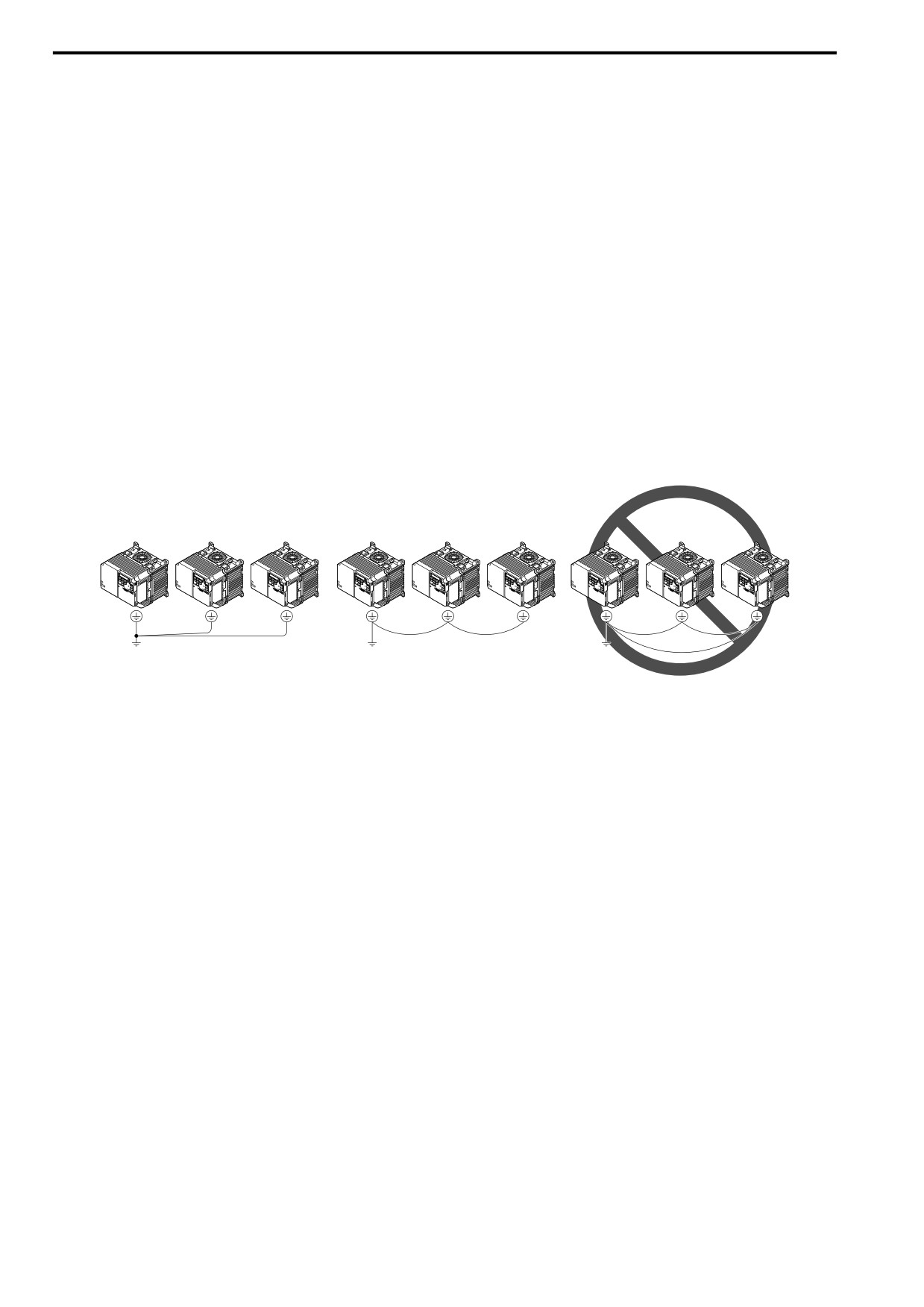
Do not loop the grounding wire when connecting more than one drive.
Figure 3.14 Wiring More than One Drive
■ Wiring the Main Circuit Terminal Block
WARNING! Electrical Shock Hazard. Before you wire the main circuit terminals, make sure that MCCB and MC are OFF. If you
touch electrical equipment when MCCB and MC are ON, it can cause serious injury or death.
■ Main Circuit Configuration
WARNING! Fire Hazard. Do not connect a braking resistor to terminals +1 or -. Use terminals B1 and B2 for the braking resistor
connections. If you connect a braking resistor to the incorrect terminals, it can cause damage to the drive and braking circuit and
serious injury or death.
NOTICE: Do not use the negative DC bus terminal “-” as a ground terminal. This terminal is at high DC voltage potential.
Incorrect wiring connections can cause damage to the drive.
Note:
Drive model B018 does not have a built-in EMC filter.
68
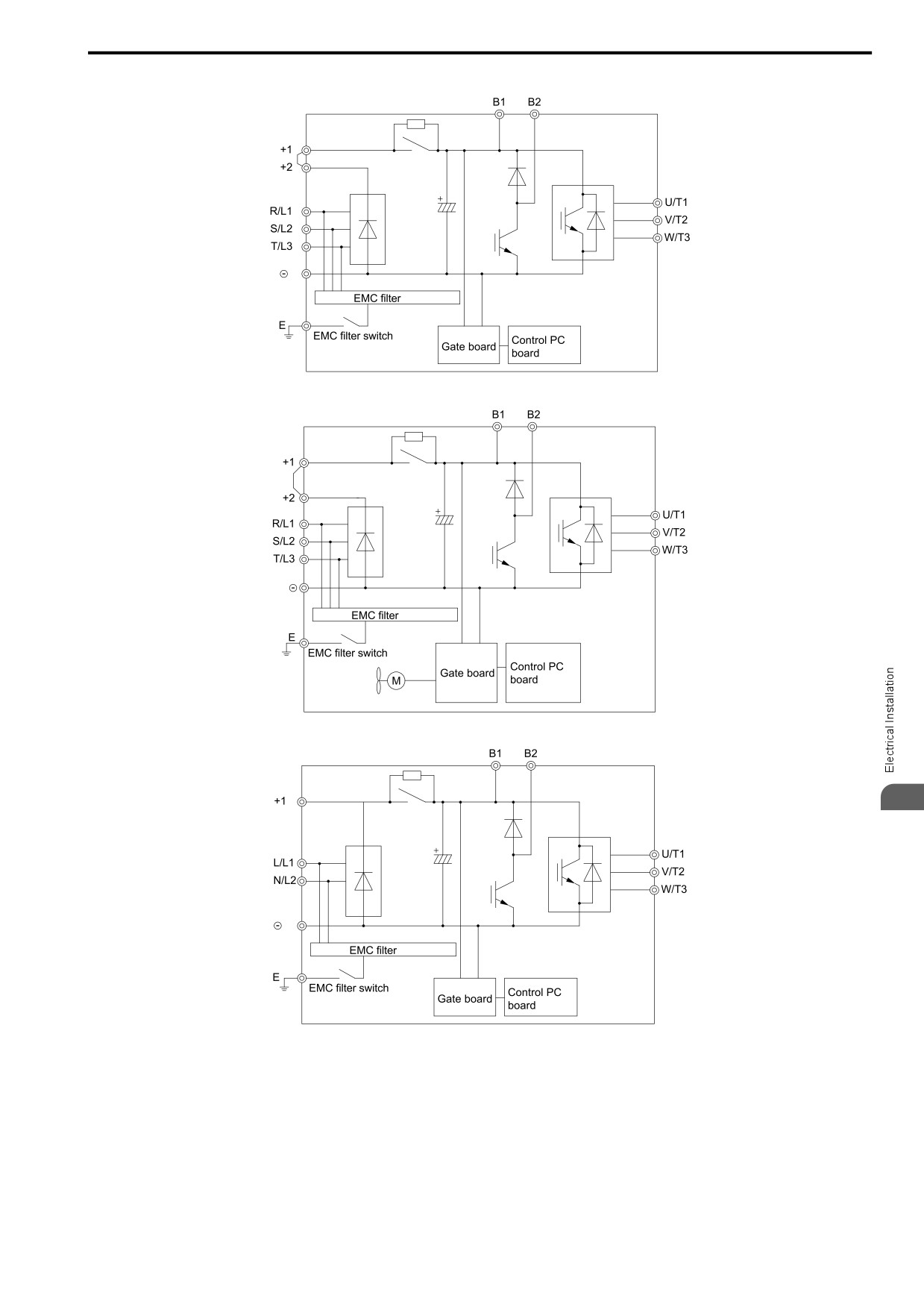
3.3 Main Circuit Wiring
Models 2001 - 2004, 4001 - 4004
Models 2006 - 2082, 4005 - 4060
Models B001 - B004
3
69
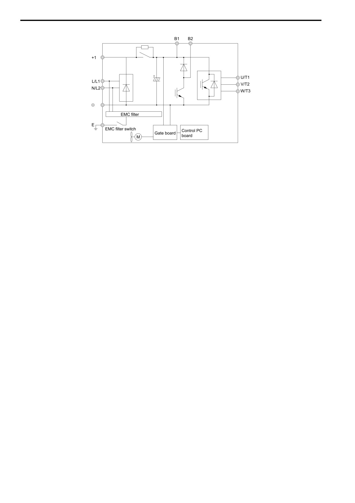
3.3 Main Circuit Wiring
Models B006 - B012
70
3.4 Main Circuit Terminal Block Wiring Procedure
3.4
Main Circuit Terminal Block Wiring Procedure
DANGER! Electrical Shock Hazard. Do not examine, connect, or disconnect wiring on an energized drive. Before servicing,
disconnect all power to the equipment and wait for the time specified on the warning label at a minimum. The internal capacitor
stays charged after the drive is de-energized. The charge indicator LED extinguishes when the DC bus voltage decreases
below 50 Vdc. When all indicators are OFF, measure for dangerous voltages to make sure that the drive is safe. If you do work
on the drive when it is energized, it will cause serious injury or death from electrical shock. The drive has internal capacitors that
stay charged after you de-energize the drive.
◆ Notes on Wiring the Main Circuit Terminal Block
Read these notes before you wire the main circuit terminal block.
• Use UL-Listed, vinyl-coated insulated copper wires for operation with a continuous maximum permitted
temperature of 75 °C at 600 V.
• Remove all unwanted objects that are near the terminal block connections.
• Remove the insulation from the connection wires to the wire stripping lengths shown in the manual.
• Do not use bent or crushed wires. Remove the damaged end of the wire before you use it. Incorrect connections
can cause death or serious injury from fire.
• Do not solder stranded wire. Soldered wire connections can become loose over time and cause unsatisfactory
drive performance.
• If you use stranded wire, make sure that all of the wire strands are in the connection. Also, do not twist the
stranded wire too much. Incorrect connections can cause death or serious injury from fire.
• Put the wire all the way into the terminal block. Remove the insulation from the wire to the recommended wire
stripping length to fit the wire with insulation in the plastic housing.
• Use a torque driver, torque ratchet, or torque wrench for the screws. A slotted driver or a hex tool will be
necessary to wire the screw clamp terminal. Use applicable tools as specified by the recommended conditions in
the product manual.
• If you use power tools to tighten the terminal screws, use a low speed setting (300 to 400 r/min). Failure to obey
can cause damage to the terminal screws.
• Wire gauges on existing drive models to be replaced may not match wire gauge ranges on new drives. Refer to
the drive manuals for correct wire sizes.
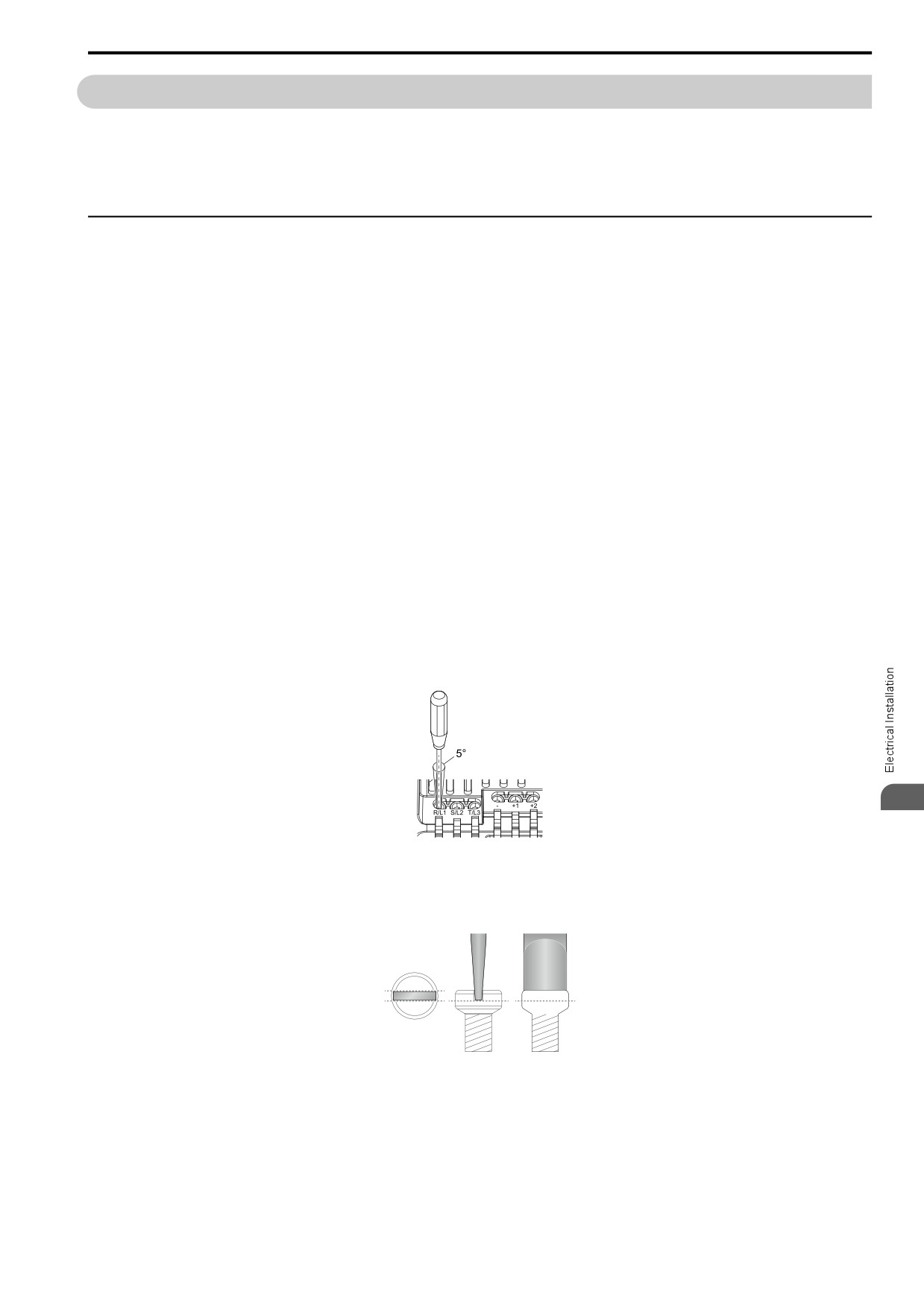
• Do not tighten the terminal screws at an angle
of 5 degrees or more. Failure to obey can cause damage to the
terminal screws.
3
Figure 3.15 Permitted Angle
• Put the bit all the way into the hex socket to tighten
the hex socket cap screw.
• When you tighten slotted screws, hold the straight-edge
screwdriver
perpendicularly to the screw. Make sure
that you align the end of the straight-edge screwdriver with the
screw groove.
Figure 3.16 Tightening Slotted Screws
• After connecting the wires to the terminal block, lightly pull on the wires to make sure that they do not come out
of the terminals.
• Do not let strain on the wiring cause damage. Use a strain relief near the wiring to release the tension. Refer to
Figure 3.17 for an example.
71
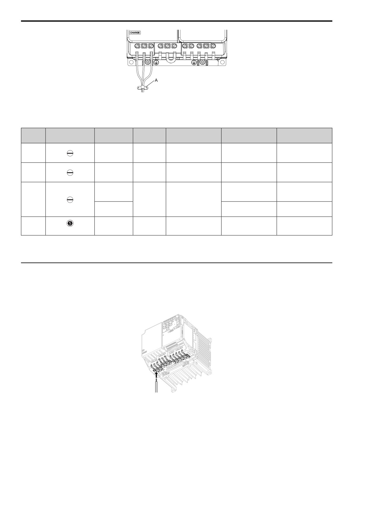
3.4 Main Circuit Terminal Block Wiring Procedure
A - Cable clamp
Figure 3.17 Strain Relief Example
Table 3.4 Recommended Wiring Tools
Screw
Bit Model
Torque Driver Model
Torque Wrench
Screw Shape
Wire Gauge
Adapter
Size
(Manufacturer)
(Tightening Torque)
(Tightening Torque)
TSD-M 1,2NM
SF-BIT-SL 0,5X3,0-70
M3
-
Bit
(0.3 - 1.2 N∙m
-
(PHOENIX CONTACT)
(2.7 - 10.6 in∙lb))
TSD-M 3NM
SF-BIT-SL 1,0X4,0-70
M4
-
Bit
(1.2 - 3.0 N∙m
-
(PHOENIX CONTACT)
(10.6 - 26.6 in∙lb))
TSD-M 3NM
≤ 25 mm2
(1.2 - 3.0 N∙m
-
(AWG 10)
SF-BIT-SL 1,2X6,5-70
(10.6 - 26.6 in∙lb))
M5 *1
Bit
(PHOENIX CONTACT)
≥ 30 mm2
4.1 - 4.5 N∙m
-
(AWG 8)
(36.3 - 39.8 in∙lb) *2 *3
SF-BIT-HEX 5-50
5 - 9 N∙m
M6
-
Bit
-
(WAF: 5 mm)
(PHOENIX CONTACT)
(44.3 - 79.7 in∙lb) *2 *3
*1
When you wire drive models 2042, 2056, 4031, 4038, 4044, and 4060, select the correct tools for the wire gauge.
*2
Use 6.35 mm (0.25 in) bit socket holder.
*3
Use a torque wrench that can apply this torque measurement range.
◆ Main Circuit Terminal Block Wiring Procedure
When terminals R/L1, S/L2, T/L3, -, +1, and +2 have IP20 protection covers, remove them.
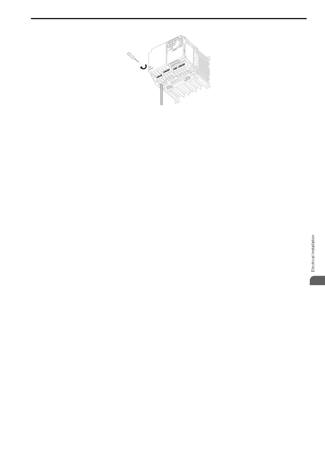
1. Put a wire with prepared ends into the main circuit terminal block.
Look through the opening in the drive case to make sure that you correctly installed the wires into the
terminal block.
Figure 3.18 Install the Electrical Wire
Note:
There is a jumper between terminals +1 and +2. Remove the jumper, then wire to terminals +1 and +2.
72
3.4 Main Circuit Terminal Block Wiring Procedure
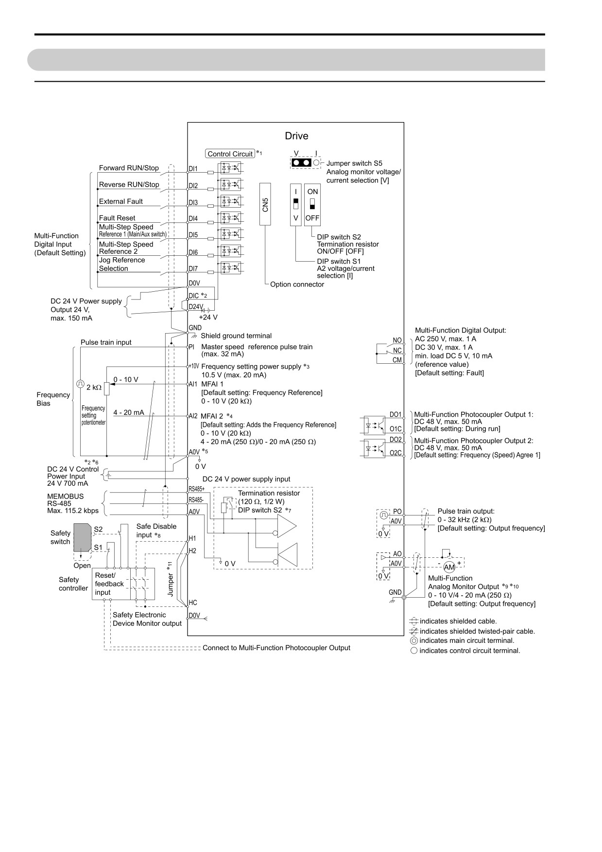
2. Tighten the screws to the specified torque.
Figure 3.19 Tighten Terminal Block Screws
If you removed IP20 protection covers, install them into their initial positions.
3
73
3.5 Control Circuit Wiring
3.5
Control Circuit Wiring
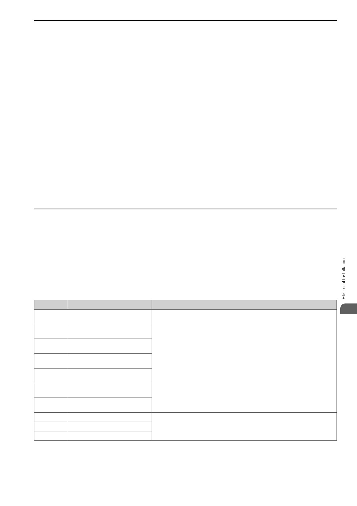
◆ Control Circuit Connection Diagram
Wire the drive control circuit as shown.
E24
Figure 3.20 Control Circuit Connection Diagram
*1 Connect a 24 V power supply to terminals E24V-A0V to operate the control circuit while the main circuit power supply is OFF.
74
3.5 Control Circuit Wiring
*2
Install the wire jumpers between terminals DIC-D24V and DIC-D0V to set the MFDI power supply (sinking/sourcing mode or
internal/external power supply).
NOTICE: Do not close the circuit between terminals D24V and D0V. A closed circuit between these terminals will cause
damage to the drive.
• Sinking Mode: Install a jumper between terminals DIC and D24V.
NOTICE: Do not close the circuit between terminals DIC and D0V. A closed circuit between these terminals will cause
damage to the drive.
• Sourcing Mode: Install a jumper between terminals DIC and D0V.
NOTICE: Do not close the circuit between terminals DIC and D24V. A closed circuit between these terminals will cause
damage to the drive.
• External Power Supply: No jumper is necessary between terminals DIC-D0V and terminals DIC-D24V.
*3
The maximum output current capacity for terminal +10V on the control circuit is 20 mA.
NOTICE: Damage to Equipment. Do not install a jumper between terminals +10V and A0V. A closed circuit between these
terminals will cause damage to the drive.
*4
DIP switch S1 sets terminal AI2 for voltage or current input. The default setting for S1 is current input (“I” side).
*5
Do not ground the control circuit terminals A0V or connect them to the drive.
NOTICE: Do not ground the AC control circuit terminals and only connect the A0V terminals according to the product
instructions. If you connect the AC terminals incorrectly, it can cause damage to the drive.
*6 Do not connect terminals E24V and A0V inversely. Failure to obey will cause damage to the drive.
*7 Set DIP switch S2 to the ON position to enable the termination resistor in the last drive when you use Modbus communications.
*8 To use the internal power supply with the Safe Disable input, use sourcing mode.
*9 Disconnect the wire jumpers between H1 and HC and H2 and HC to use the Safe Disable input.
*10 Use multi-function analog monitor outputs with analog frequency meters, ammeters, voltmeters, and wattmeters. Do not use monitor
outputs with feedback-type signal devices.
*11
Jumper S5 sets terminal AO for voltage or current output. The default setting for S5 is voltage output (“V” side).
◆ Control Circuit Terminal Block Functions
Hx-xx parameters set functions for the multi-function input and output terminals.
WARNING! Sudden Movement Hazard. Correctly wire and test all control circuits to make sure that the control circuits operate
correctly. If you use a drive that has incorrect control circuit wiring or operation, it can cause death or serious injury.
NOTICE: The drive can fail if users frequently turn the drive ON and OFF with the MC on the power source side to Run and
Stop the drive. Incorrect operation can decrease the service life of the relay contacts and electrolytic capacitors. If you
frequently use the magnetic contactor on the power source side to Run and Stop the drive, it can cause drive failure.
■ Multi-function Input Terminals
This chapter contains a list of input terminals and functions.
Table 3.5 Digital Inputs
Terminal
Name (Default)
Function (Signal Level)
3
MFDI selection 1
DI1
(ON: Forward run OFF: Stop)
• Photocoupler
MFDI selection 2
DI2
•
24 V, 6 mA
(ON: Reverse run OFF: Stop)
Note:
MFDI selection 3
To set the MFDI power supply (Sinking/Sourcing Mode or internal/external power supply), install wire
DI3
jumpers between terminals DIC-D24V and DIC-D0V.
(External fault (N.O.))
• Sinking Mode: Install a jumper between terminals DIC and D24V.
MFDI selection 4
NOTICE: Do not close the circuit between terminals DIC and D0V. A
DI4
(Fault reset)
closed circuit between these terminals will cause damage to the drive.
MFDI selection 5
• Sourcing Mode: Install a jumper between terminals DIC and D0V.
DI5
(Multi-step speed reference 1)
NOTICE: Do not close the circuit between terminals DIC and D24V. A
closed circuit between these terminals will cause damage to the drive.
MFDI selection 6
DI6
(Multi-step speed reference 2)
• External Power Supply: No jumper is necessary between terminals DIC-D0V and terminals DIC-
D24V.
MFDI selection 7
DI7
(Jog command)
D0V
MFDI power supply 0 V
MFDI power supply, 24 V (maximum 150 mA)
DIC
MFDI selection common
NOTICE: Do not close the circuit between terminals D24V and D0V. A
closed circuit between these terminals will cause damage to the drive.
D24V
MFDI power supply +24 Vdc
75
3.5 Control Circuit Wiring
Table 3.6 Safe Disable Input
Terminal
Name (Default)
Function (Signal Level)
H1
Safe Disable input 1
Remove the jumper between terminals H1-HC and H2-HC to use the Safe Disable input.
•
24 V, 6 mA
•
ON: Normal operation
•
OFF: Coasting motor
H2
Safe Disable input 2
•
Internal impedance 4.7 kΩ
•
OFF Minimum OFF time of 3 ms.
Safe Disable function common
HC
Safe Disable function common
NOTICE: Do not close the circuit between terminals HC and D0V. A closed
circuit between these terminals will cause damage to the drive.
Table
3.7 Master Frequency Reference
Terminal
Name (Default)
Function (Signal Level)
• Response frequency: 0 Hz to 32 kHz
• H level duty: 30% to 70%
Master frequency reference pulse train input
PI
• H level voltage: 3.5 V to 13.2 V
(Master frequency reference)
• L level voltage: 0.0 V to 0.8 V
• Input impedance: 3 kΩ
+10V
Power supply for frequency setting
10.5 V (allowable current 20 mA maximum)
MFAI1
Voltage input
AI1
(Master frequency reference)
•
0 V to 10 V/100% (input impedance: 20 kΩ)
Voltage input or current input
MFAI2
Use DIP switch S1 and H3-09 [AI2 Signal Level Select] to select the input.
AI2
(Combined to terminal AI1)
•
0 V to 10 V/100% (input impedance: 20 kΩ)
•
4 mA to 20 mA/100%, 0 mA to 20 mA/100% (input impedance: 250 Ω)
A0V
Frequency reference common
0V
GND
Connecting shielded cable
-
■ Output Terminals
This chapter contains a list of Output terminals and functions.
Table 3.8 Digital Outputs
Terminal
Name (Default)
Function (Signal Level)
N.O. output
NO
(Fault)
• Relay output
•
30 Vdc, 10 mA to 1 A
N.C. output
NC
•
250 Vac, 10 mA to 1 A
(Fault)
•
Minimum load: 5 V, 10 mA (Reference value)
CM
Digital output common
Table 3.9 Multi-function Photocoupler Outputs
Terminal
Name (Default)
Function (Signal Level)
DO1
Multi-function photocoupler output 1
• Photocoupler output
O1C
(During RUN)
•
48 V, 2 mA to 50 mA
Note:
DO2
Multi-function photocoupler output 2
Connect a flywheel diode when you drive a reactive load such as a relay coil. Make sure that the diode
(Speed agree 1)
rating is larger than the circuit voltage.
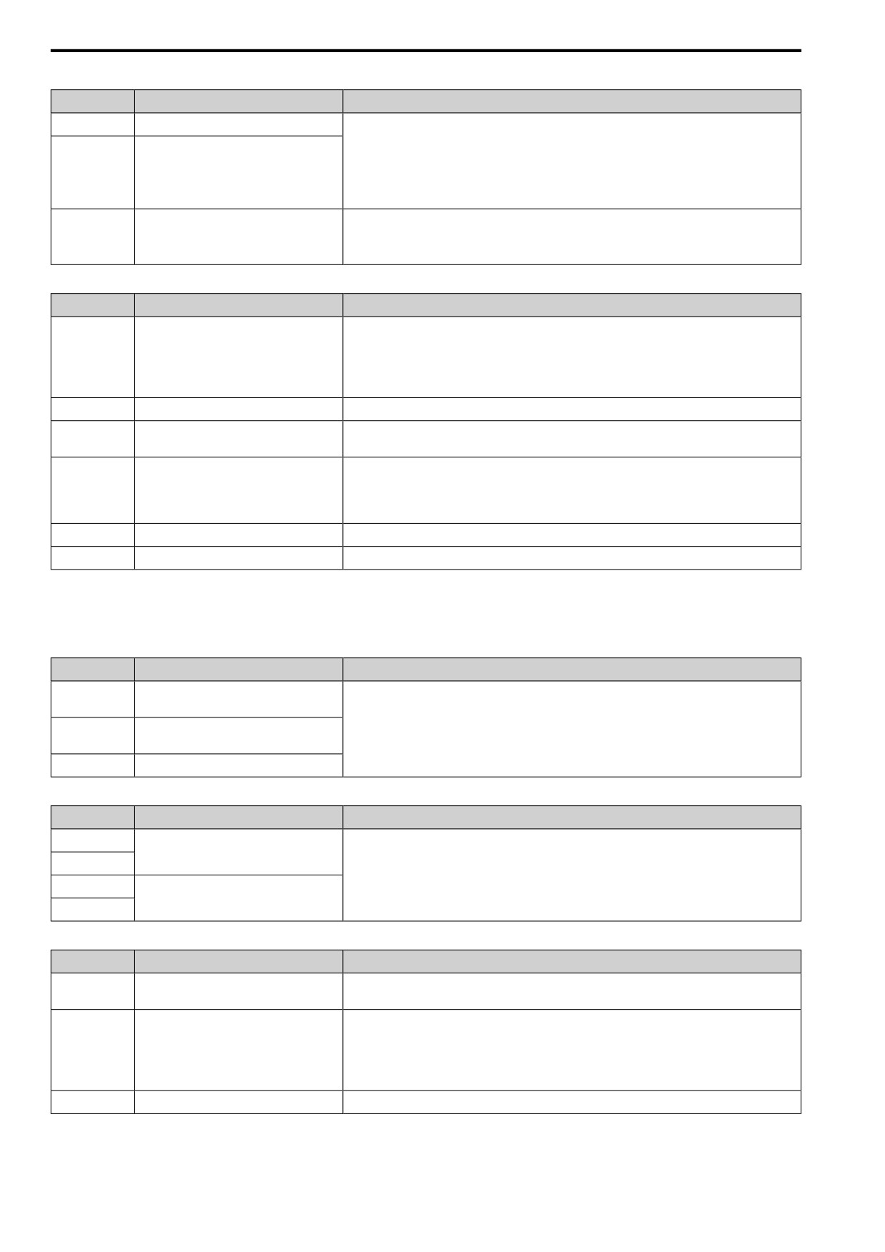
O2C
Table 3.10 Control Circuit Monitor Output Terminals
Terminal
Name (Default)
Function (Signal Level)
Pulse train output
32 kHz (maximum)
PO
(Output frequency)
Refer to “Pulse Train Output” for more information.
Select voltage or current output.
•
0 V to 10 V/0% to 100%
Analog monitor output
AO
•
4 mA to 20 mA (Receiver recommended impedance: 250 Ω)
(Output frequency)
Note:
Select using jumper switch S5 and H4-07 [AO Signal Level Select].
A0V
Monitor common
0V
76
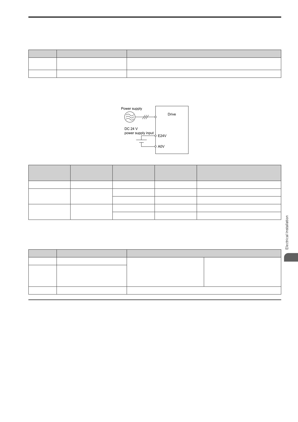
3.5 Control Circuit Wiring
■ External Power Supply Input Terminals
This chapter contains a list of the functions of the external power supply input terminals.
Table 3.11 External Power Supply Input Terminals
Terminal
Name (Default)
Function
Supplies backup power to the drive control circuit, keypad, and option board.
E24V
External 24 V power supply input
21.6 VDC to 26.4 VDC, 700 mA
A0V
External 24 V power supply ground
0V
Alarm Display When You Use External 24 V Power Supply
When you use an external 24 V power supply, an alarm is detected as shown below if you set o2-23 [Ext24V Off
Warning Display] and o2-26 [Ext24V Mode Warning Display] for the main circuit power supply. Set the alarm
display as needed.
Table 3.12 Power Supply Used and the Alarm Display
o2-23
o2-26
Main circuit power
External 24 V power
[Ext24V Off Warning
[Ext24V Mode Warning
Alarm display
supply
supply
Display]
Display]
ON
ON
-
-
-
ON
OFF
0 [Disabled]
-
-
1 [Enabled]
-
L24v [Loss of External Power 24 Supply]
OFF
ON
-
0 [Disabled]
"Ready" LED light flashes quickly
-
1 [Enabled]
EP24v [External Power 24V Supply]
■ Serial Communication Terminals
This chapter contains a list of serial communication terminals and functions.
Table 3.13 Modbus Communication
Terminal
Terminal Name
Function (Signal Level)
3
RS485+
Communication input/output (+)
Modbus communications
Use an RS-485 cable to connect the drive.
• RS-485
Note:
• Modbus communication protocol
RS485-
Communication output (-)
Set DIP switch S2 to ON to enable the
• Maximum 115.2 kbps
termination resistor in the last drive in a Modbus
network.
A0V
Signal ground
0V
◆ Control Circuit Terminal Configuration
The control circuit terminals are in the positions shown in this chapter.
77
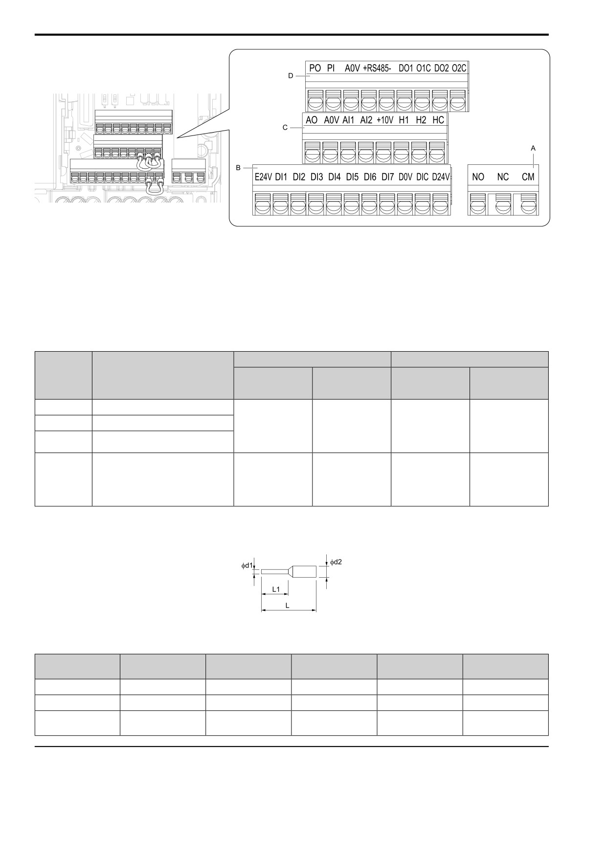
3.5
Control
Circuit Wiring
A - Terminal
block (TB2)
C - Terminal block (TB1-2)
B - Terminal block (TB1-1)
D - Terminal block (TB1-3)
Figure 3.21 Control Circuit Terminal Arrangement
■ Control Circuit Wire Gauges and Tightening Torques
Use the tables in this chapter to select the correct wires. Use shielded wire to wire the control circuit terminal
block. Use crimp ferrules on the wire ends to make the wiring procedure easier and more reliable.
Table 3.14 Control Circuit Wire Gauges and Tightening Torques
Bare Wire
Crimp Ferrule
Terminal Block
Terminal
Recommended
Recommended
Applicable Gauge
Applicable Gauge
Gauge
Gauge
mm2 (AWG)
mm2 (AWG)
mm2 (AWG)
mm2 (AWG)
TB1-1
E24V, DI1 - DI7, D0V, DIC, D24V
• Stranded wire
0.25
- 1.0
TB1-2
AO, A0V, AI1, AI2, +10V, H1, H2, HC
0.75
(24 - 17)
0.5
0.25
- 0.5
(18)
• Solid wire
(20)
(24 - 20)
PO, PI, A0V, RS485+, RS485-, DO1, O1C,
0.25
- 1.5
TB1-3
DO2, O2C
(24 - 16)
• Stranded wire
0.25
- 1.5
0.75
(24 -16)
0.5
0.25
- 1.0
TB2
NO, NC, CM
(18)
• Solid wire
(20)
(24 - 17)
0.25
- 1.5
(24 - 16)
Crimp Ferrules
Attach an insulated sleeve when you use crimp ferrules.
Use the CRIMPFOX 6, a crimping tool made by PHOENIX CONTACT.
Figure 3.22 External Dimensions of Crimp Ferrules
Table 3.15 Crimp Ferrule Models and Sizes
Wire Gauge
Model
L (mm)
L1 (mm)
φd1 (mm)
φd2 (mm)
mm2 (AWG)
0.25
(24)
AI 0.25-8YE
12.5
8
0.8
2.0
0.34
(22)
AI 0.34-8TQ
12.5
8
0.8
2.0
AI 0.5-8WH,
0.5
(20)
14
8
1.1
2.5
AI 0.5-8OG
◆ Wiring the Control Circuit Terminal
Wire the grounding terminal and main circuit terminals, then wire the control circuit terminals.
78
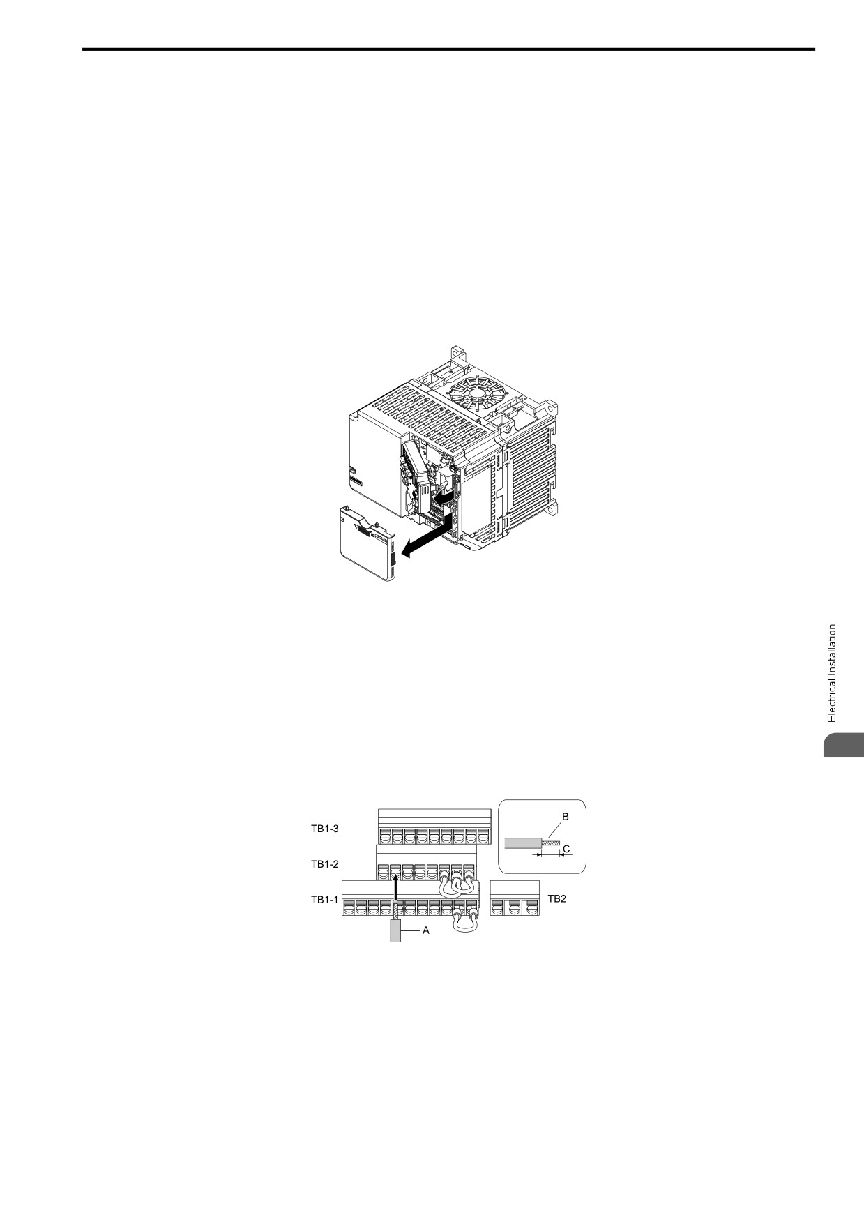
3.5 Control Circuit Wiring
WARNING! Electrical Shock Hazard. Do not remove covers or touch circuit boards while the drive is energized. If you touch the
internal components of an energized drive, it can cause serious injury or death.
NOTICE: Do not let wire shields touch other signal lines or equipment. Insulate the wire shields with electrical tape or shrink
tubing. If you do not insulate the wire shields, it can cause a short circuit and damage the drive.
Note:
• Use a Class 2 power supply to connect external power to the control terminals. If the power supply for peripheral devices is incorrect, it
can cause a decrease in drive performance.
• Connect the shield of shielded cable to the applicable ground terminal. Incorrect equipment grounding can cause drive or equipment
malfunction from electrical interference.
• Isolate wiring for contact output terminals NO, NC, CM, DO1, O1C, DO2, and O2C from other control circuit wiring. The drive and
connected equipment will malfunction or the drive can trip because of incorrect wiring.
• Isolate control circuit wiring from main circuit wiring (terminals R/L1, S/L2, T/L3, L/L1, N/L2, B1, B2, U/T1, V/T2, W/T3, -, +1, +2)
and other high-power wiring. If control circuit wiring is adjacent to main circuit wiring, it can cause incorrect operation of the drive
and equipment from electrical interference.
1. Remove the front cover from the drive.
To move Jumper S5, also remove the keypad.
Figure 3.23 Remove the Front Cover
2. Refer to the following figure and wire the control circuit.
Use a flat bladed screwdriver with a blade width of 2 .5mm (0.1 in) or less and thickness of 0.4 mm (0.01
in) or less.
WARNING! Fire Hazard. Tighten all terminal screws to the correct tightening torque. Connections that are too loose or
too tight can cause incorrect operation and damage to the drive. Incorrect connections can also cause death or
serious injury from fire.
Note:
• Use shielded, twisted-pair wires and ground the shield to the ground terminal of the drive. Incorrect equipment grounding
3
can cause drive or equipment malfunction from electrical interference.
• Do not use control circuit wiring that is longer than 50 m (164 ft) to supply the analog frequency reference from a remote
source. If the control circuit wiring is too long, it can cause unsatisfactory system performance.
A - Wire with a crimp ferrule attached, or
C - Remove approximately 5.5 mm (0.21 in) of the
unsoldered wire with the core wires lightly
covering at the end of the wire if you do not use
twisted
crimp ferrules.
B - Pull back the shielding and lightly twist the end
with your fingers to keep the ends from fraying.
Figure 3.24 Wiring Procedure for the Control Circuit
Note:
• Do not solder the core wire. Soldered wiring connections can become loose and cause the drive to malfunction.
• Prepare the wire ends of shielded twisted-pair wires as shown below to use an analog reference from an external frequency
setting potentiometer to set the frequency. Connect the shield to terminal GND of the drive.
79
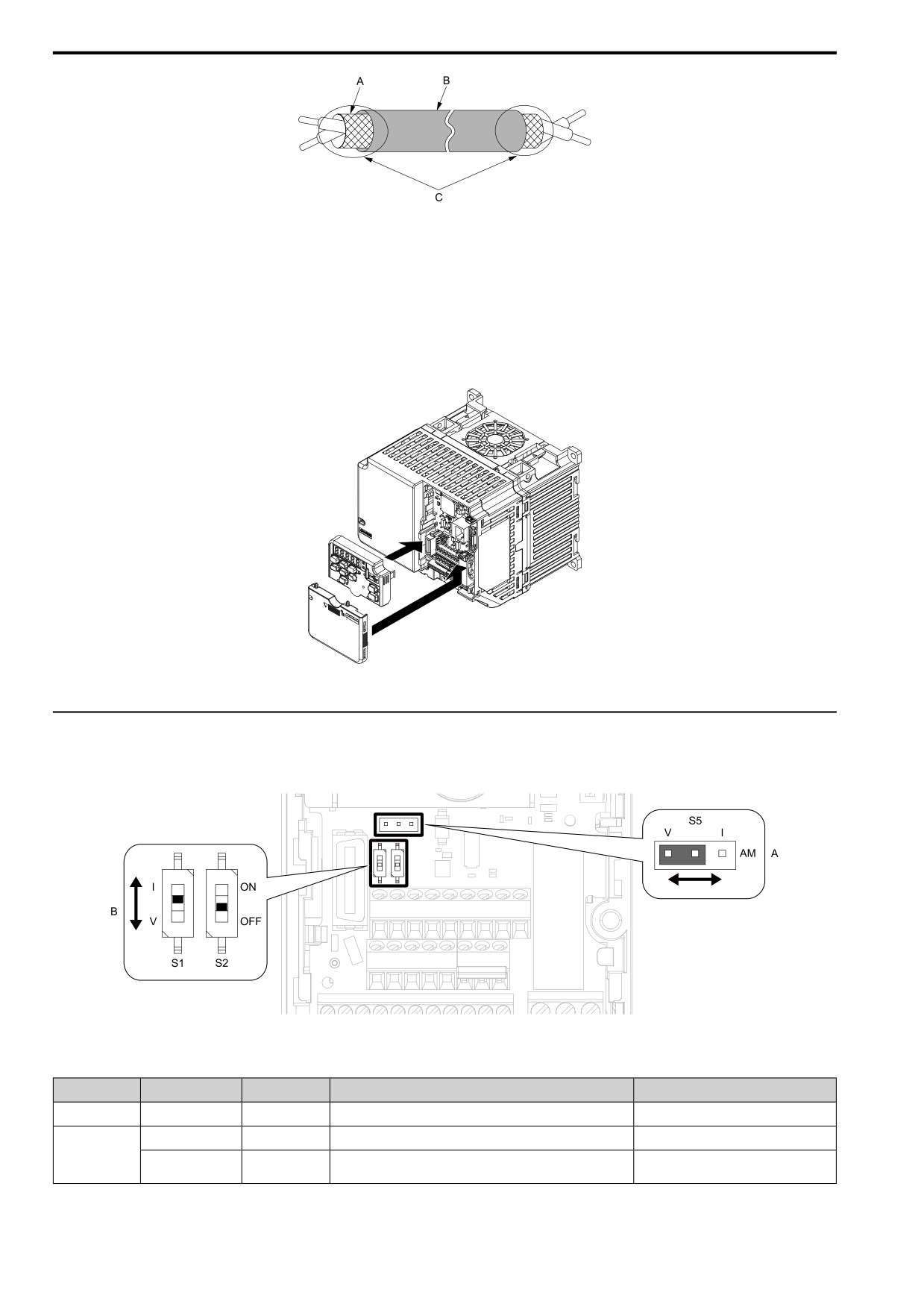
3.5 Control Circuit Wiring
A - Connect the shield to terminal GND of the drive. C - Insulate with electrical tape or shrink tubing.
B - Sheath
Figure 3.25 Prepare the Ends of Shielded Wire
3. Attach the front cover.
If you moved Jumper S5, attach the keypad before you attach the front cover.
If you did not move Jumper S5, attach the front cover.
Make sure that you do not pinch wires or signal lines between the front cover and the drive before you
reattach the cover.
Figure 3.26 Reattach the Front Cover
◆ Switches and Jumpers
on the Terminal Board
The terminal board has switches to adapt the drive I/Os to the external control signals. Set the switches to select
the functions for each terminal.
Figure 3.27 Locations of Switches
Table 3.16 I/O Terminals and Switches Functions
Position
Switch
Terminal
Function
Default
A
Jumper switch S5
AO
Sets the output method for terminal AO (voltage or current).
V (voltage output)
DIP switch S1
AI2
Sets the input
method
for
terminal
AI2 (voltage or current).
I (current input)
B
Enables and disables
the Modbus communications termination
DIP Switch S2
-
OFF
resistor.
80
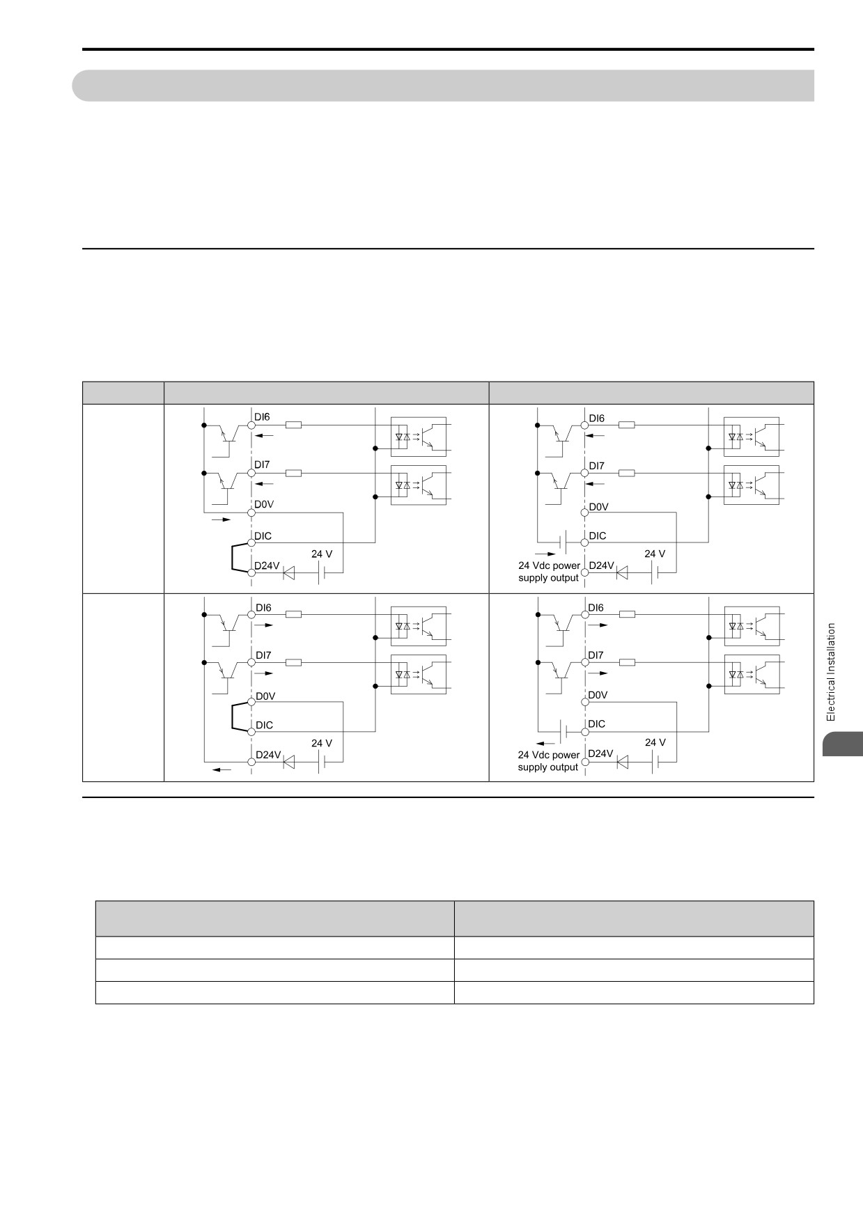
3.6 Control I/O Connections
3.6
Control I/O Connections
This section gives information about the settings for the listed control circuit I/O signals.
• MFDI (terminals DI1 to DI7)
• Pulse train output (terminal PO)
• MFAI (terminal AI2)
• MFAO (terminal AO)
• Modbus communications (terminals RS485+, RS485-, A0V)
◆ Set Sinking Mode/Sourcing Mode
Close the circuit between terminals DIC-D24V and DIC-D0V to set the sinking mode/sourcing mode and the
internal/external power supply for the MFDI terminals. The default setting for the drive is internal power supply
sinking mode.
NOTICE: Do not close the circuit between terminals D24V and D0V. A closed circuit between these terminals will cause
damage to the drive.
Mode
Internal Power Supply (Terminal D0V-D24V)
External 24 V power supply
Sinking Mode
(NPN)
Sourcing Mode
(PNP)
3
◆ Pulse Train Output
You can use pulse train monitor output terminal PO for sourcing mode or for sinking mode.
• Use for sourcing mode
The load impedance changes the voltage level of the pulse train output signal.
Load Impedance
Output Voltage
RL(kΩ)
VPO(V)
1.5 kΩ or more
5 Vor more
4.0 kΩ or more
8 Vor more
10 kΩ or more
10 V or more
Note:
Use the formula below to calculate the necessary load resistance (kΩ) to increase output voltage VPO(V).
81