Q2V Driving Quality. Technical Manual (Item code: Q2V-Axxxx-xxx, 2020) - page 1
Q2V
Driving Quality
Technical Manual
Item code: Q2V-Axxxx-xxx
200 V Class, Three-Phase: 0.1 to 22 kW 200
V Class, Single-Phase: 0.1 to 4.0 kW 400
V Class, Three-Phase: 0.37 to 30 kW
Table of Contents
i.
Preface and General Precautions
13
i.1
Safety Information
14
General Safety Precautions
14
Warning Label Content and Location
16
i.2
Legal Information
17
Exclusion of Liability
17
About Registered Trademarks
17
1.
Receiving
19
1.1
Model Number and Nameplate Check
20
Nameplate
20
How to Read Model Numbers
20
1.2
Features and Advantages of Control Methods
23
2.
Mechanical Installation
27
2.1
Safety Precautions
28
2.2
Installation Environment
29
2.3
Installation Position and Distance
30
2.4
Moving the Drive
32
2.5
Removing/Reattaching Covers
33
Remove the Front Cover
33
Reattach the Front Cover
33
2.6
Remove and Reattach the Keypad
35
Remove the Keypad
35
Reattach the Keypad
35
2.7
Install the Keypad to a Control Panel or Another Device
36
2.8
Installation Methods
37
Standard Installation
37
External Heatsink
37
3.
Electrical Installation
39
3.1
Safety Precautions
40
3.2
Standard Connection Diagram
42
3.3
Main Circuit Wiring
45
Motor and Main Circuit Connections
45
Configuration of Main Circuit Terminal Block
46
Main Circuit Terminal Functions
50
Wire Selection
50
Main Circuit Terminal and Motor Wiring
67
3.4
Main Circuit Terminal Block Wiring Procedure
71
Notes on Wiring the Main Circuit Terminal Block
71
Main Circuit Terminal Block Wiring Procedure
72
3
3.5
Control Circuit Wiring
74
Control Circuit Connection Diagram
74
Control Circuit Terminal Block Functions
75
Control Circuit Terminal Configuration
77
Wiring the Control Circuit Terminal
78
Switches and Jumpers on the Terminal Board
80
3.6
Control I/O Connections
81
Set Sinking Mode/Sourcing Mode
81
Pulse Train Output
81
Set the Input Signal for the MFAI Terminal AI2
82
Set the Output Signal for the MFAO Terminal AO
83
Switch ON Termination Resistor for Modbus Communications
83
3.7
Connect the Drive to a PC
84
3.8
External Interlock
85
3.9
Braking Resistor Installation
86
Install a Braking Resistor: ERF-Type
86
Install a Braking Resistor Unit: LKEB-Type
86
Dynamic Braking Option Overload Protection
87
3.10
Drive Wiring Protection
88
Installing a Earth Leakage Circuit Breaker (RCM/RCD)
88
Install a Molded-Case Circuit Breaker (MCCB) or Residual Current Monitor/Device
(RCM/RCD)
88
3.11
Dynamic Braking Option, Motor Protection
89
Install an Electromagnetic Contactor (MC) at the Input Side of the Drive
89
Install a Thermal Overload Relay on the Drive Output
89
3.12
Improve the Power Factor
91
Connect an AC Reactor
91
Connect a DC Reactor
91
3.13
Prevent Switching Surge
92
3.14
Decrease Noise
93
Connect a Noise Filter to the Input Side (Primary Side)
93
Connect a Noise Filter to the Output Side (Secondary Side)
93
3.15
Protect the Drive during Failures
95
Three-Phase 200 V Class
95
Single-Phase 200 V Class
95
Three-Phase 400 V Class
96
3.16
Wiring Checklist
97
3.17
Motor Application Precautions
99
Precautions for Existing Standard Motors
99
Precautions for PM Motors
100
Precautions for Specialized Motors
100
Notes on the Power Transmission Mechanism
101
4.
Startup Procedure and Test Run
103
4.1
Safety Precautions
104
4.2
Component Names and Functions
105
LED Flashing Statuses
106
Keypad Mode and Menu Displays
107
4.3
Set up the Drive with Manual Setup Mode
108
4.4
Drive Mode and Programming Mode
109
Drive Mode
110
Programming Mode
110
Change Parameter Settings
110
Verify and Set the Changed Parameters (Verify Menu)
111
4
How to Switch between LOCAL and REMOTE
111
4.5
Start-up Procedures
113
Flowchart A: Connect and Run the Motor with Minimal Setting Changes
113
Sub-Chart A-1: Induction Motor Auto-Tuning and Test Run Procedure
114
Sub-Chart A-2: PM Motor Auto-Tuning and Test Run Procedure
114
Sub-Chart A-3: EZ Open Loop Vector Control Test Run Procedure
115
4.6
Items to Check before Starting Up the Drive
117
Check before You Energize the Drive
117
Check after You Energize the Drive
117
4.7
Keypad Operation
118
Digital Character Mapping Table
118
Show the Monitor
118
Check Modified Parameters
118
Set and View Necessary Parameters
119
Change Parameter Settings
119
Save a Backup of Parameters
120
Write Backed-up Parameters to the Drive
121
Verify Keypad Parameters and Drive Parameters
121
Delete Parameters Backed Up to the Keypad
122
4.8
Automatic Parameter Settings Optimized for Specific Applications (Application
Presets)
123
4.9
Auto-Tuning
124
Auto-Tuning for Induction Motors
124
Auto-Tuning for PM Motors
125
Auto-Tuning in EZ Open Loop Vector Control Method
126
ASR and Inertia Tuning
127
Precautions before Auto-Tuning
128
4.10
Test Run
130
No-Load Test Run
130
Do a No-Load Test Run
130
Actual-Load Test Run
130
Do an Actual-Load Test Run
131
4.11
Fine Tuning during Test Runs (Adjust the Control Function)
132
V/f Control
132
Open Loop Vector Control Method
132
Fine-Tuning Open Loop Vector Control for PM Motors
134
Advanced Open Loop Vector Control Method for PM
135
EZ Open Loop Vector Control Method
135
4.12
Test Run Checklist
136
5.
Standards Compliance
139
5.1
Safety Precautions
140
5.2
European Standards
142
EU Declaration of Conformity
143
CE Low Voltage Directive Compliance
147
EMC Directive
158
5.3
UL Standards
166
Area of Use
166
Wire the Main Circuit Terminal Block
166
Low Voltage Wiring for Control Circuit Terminals
177
Drive Motor Overload and Overheat Protection
177
5.4
对应中国RoHS指令
178
本产品中含有有害物质的信息
178
5.5
China RoHS Compliance
179
Information on Hazardous Substances in This Product
179
5
5.6
Safe Disable Input
180
Safe Disable Specifications
180
Safety Precautions
181
Safe Disable Circuit
181
Connect Safe Disable Input Contacts to Multiple Drives
182
Enabling and Disabling the Drive Output (“Safe Torque Off”)
184
Safe Disable Monitor Output Function and Keypad Display
185
Validating the Safe Disable Function
186
6.
Network Communications
187
6.1
Safety Precautions
188
6.2
Field Bus Network Support
189
6.3
Modbus Communications
190
Configure Master/Slave
190
Communication Specifications
190
Communication with the PLC
190
Modbus Drive Operations
192
Communications Timing
192
Message Format
193
Examples of Messages for Commands/Responses
195
Enter Command
199
Self-Diagnostics
199
Communications Data Table
200
Error Codes
211
7.
Troubleshooting
213
7.1
Safety Precautions
214
7.2
Types of Faults, Minor Faults, Alarms, and Errors
216
7.3
List of Fault, Minor Fault, Alarm, and Error Codes
217
7.4
Faults
222
7.5
Minor Faults/Alarms
238
7.6
Parameter Setting Errors
247
7.7
Auto-Tuning Errors
251
7.8
Backup Function Operating Mode Display and Errors
255
7.9
Diagnosing and Resetting Faults
257
Fault Occurs Without Power Loss
257
Fault Reset Procedure
257
7.10
Troubleshooting Without Fault Display
258
Typical Problems
258
The Parameter Settings Will Not Change
258
The Motor Does Not Rotate After Entering Run Command
259
The Motor Rotates in the Opposite Direction from the Run Command
260
The Motor Rotates in Only One Direction
260
The Motor Is Too Hot
260
The Correct Auto-Tuning Mode Is Not Available
261
The Motor Stalls during Acceleration or Accel/Decel Time Is Too Long
261
The Drive Frequency Reference Is Different than the Controller Frequency Reference
Command
262
The Motor Speed Is Not Stable When Using a PM Motor
262
There Is Too Much Motor Oscillation and the Rotation Is Irregular
262
Deceleration Takes Longer Than Expected When Dynamic Braking Is Enabled
262
The Load Falls When a Brake Is Applied
263
There Is Audible Noise from the Drive or Motor Cables When the Drive Is
Energized
263
Residual Current Monitoring/Detection (RCM/RCD) Trips During Run
263
Motor Rotation Causes Unexpected Audible Noise from Connected Machinery
263
6
Motor Rotation Causes Oscillation or Hunting
263
PID Output Fault
264
The Starting Torque Is Not Sufficient
264
The Motor Rotates after the Drive Output Is Shut Off
264
The Output Frequency Is Lower Than the Frequency Reference
264
The Motor Is Making an Audible Noise
264
The Motor Will Not Restart after a Loss of Power
265
8.
Periodic Inspection and Maintenance
267
8.1
Safety Precautions
268
8.2
Inspection
270
Recommended Daily Inspection
270
Recommended Periodic Inspection
270
8.3
Maintenance
272
8.4
Replace Cooling Fans
274
Replace the Cooling Fan
274
Replace the Cooling Fan
276
8.5
Replace the Drive
279
About the Control Circuit Board
279
Replace the Drive
279
8.6
Storage Guidelines
283
9.
Disposal
285
9.1
Safety Precautions
286
9.2
Disposal Instructions
287
9.3
WEEE Directive
288
10. Specifications
289
10.1
Safety Precautions
290
10.2
Drive Duty Modes
291
10.3
Model Specifications (Three-Phase 200 V Class)
292
10.4
Model Specifications (Single-Phase 200 V Class)
295
10.5
Model Specifications (Three-Phase 400 V Class)
296
10.6
Drive Specifications
298
10.7
Drive Derating
301
Carrier Frequency Settings and Rated Current Values
301
Derating Depending on Ambient Temperature
303
Altitude Derating
303
10.8
Drive Models and Drive Watt Loss
304
Drive Watt Loss
304
10.9
Drive Exterior and Mounting Dimensions
307
IP20/UL Open Type (Models 2001 to 2006, B001 to B004)
307
IP20/UL Open Type (Models 2010 to 2021, B006 to B018, 4001 to 4012)
308
IP20/UL Open Type (Models 2030 to 2082, 4018 to 4060)
309
10.10 Peripheral Devices and Options
311
11. Parameter List
313
11.1
How to Read the Parameter List
314
Icons and Terms that Identify Parameters and Control Modes
314
11.2
Parameter Groups
315
11.3
A: INITIALIZATION
316
A1: INITIALIZATION
316
A2: MANUAL SELECTION
317
7
11.4
b: APPLICATION
318
b1: OPERATION MODE SELECT
318
b2: DC INJ / SHORT CKT BRAKE
319
b3: SPEED SEARCH
319
b4: TIMER
321
b5: PID CONTROL
322
b6: DWELL FUNCTION
325
b8: ENERGY SAVING
325
11.5
C: TUNING
327
C1: ACCEL / DECEL
327
C2: JERK CONTROL
327
C3: SLIP COMPENSATION
328
C4: TORQUE COMPENSATION
329
C5: ASR - SPEED REGULATION
329
C6: DUTY AND CARRIER
330
11.6
d: REFERENCE
331
d1: FREQUENCY REFERENCE
331
d2: REFERENCE LIMITS
332
d3: JUMP FREQUENCY
332
d4: FREQUENCY UP/DOWN
333
d6: FIELD WEAKENING / FORCING
334
d7: OFFSET FREQUENCY
334
11.7
E: MOTOR
335
E1: V/F PARAMETER MOTOR 1
335
E2: MOTOR 1 PARAMETERS
336
E3: V/F PARAMETER MOTOR 2
336
E4: MOTOR 2 PARAMETERS
337
E5: PM MOTOR SETTINGS
338
E9: SIMPLE VECTOR SETTINGS
338
11.8
F: OPTIONS
340
F1: ENCODER
340
F6: COMMUNICATIONS
341
F7: ETHERNET
344
11.9
H: TERMINALS
348
H1: DIGITAL INPUTS
348
H2: DIGITAL OUTPUTS
353
H3: ANALOG INPUTS
358
H4: ANALOG OUTPUTS
360
H5: MODBUS PORTS
361
H6: PULSE INPUT OUTPUT
362
H7: VIRTUAL INPUT OUTPUT
363
11.10
L: PROTECTION
365
L1: MOTOR PROTECTION
365
L2: POWER LOSS RIDE THROUGH
366
L3: STALL PREVENTION
367
L4: SPEED DETECTION
369
L5: FAULT RESTART
369
L6: TORQUE DETECTION
370
L7: TORQUE LIMIT
372
L8: DRIVE PROTECTION
372
11.11
n: SPECIAL
375
n1: HUNTING PREVENTION
375
n2: AFR - AUTO FREQ REGULATION
375
n3: HIGHSLIP/OVEREXCITATION BRAKE
375
n5: FEED FORWARD CONTROL
376
n6: ONLINE TUNING
376
n7: SIMPLE VECTOR TUNING
376
8
n8: PM MOTOR CONTROL TUNING
377
nA: PM MOTOR CONTROL TUNING
380
11.12
o: KEYPAD
381
o1: KEYPAD DISPLAY
381
o2: KEYPAD OPERATION
383
o3: COPY FUNCTION
384
o4: MAINTENANCE MONITORS
384
o5: DATA LOGGER
385
11.13
q: Q2PACK PARAMETERS
387
q1-01 to q8-40: Q2pack Parameters
387
11.14
r: Q2PACK JOINTS
388
r1: Q2PACK JOINTS
388
11.15
T: AUTOTUNING
389
T0: TUNE MODE
389
T1: INDUCTION MOTOR
389
T2: PM MOTOR
390
T3: ASR
391
T4: SIMPLE VECTOR
391
11.16
U: MONITORS
392
U1: STATUS
392
U2: FAULT
394
U3: FAULT HISTORY
396
U4: MAINTENANCE
396
U5: PID
399
U6: ADVANCED
400
U8: Q2PACK MONITORS
402
11.17
Parameters that Change from the Default Settings with A1-02 [Control
Method]
403
11.18
Parameters that Change from the Default Settings with E3-01 [M2 Control
Method Selection]
407
11.19
Parameters Changed by E1-03 [V/f Pattern Selection]
408
11.20
Defaults by Drive Model and Duty Rating ND/HD
409
Three-Phase 200 V Class
409
Single-Phase 200 V Class
413
Three-Phase 400 V Class
416
11.21
Parameters Changed by PM Motor Code Selection
421
Yaskawa SMRA Series SPM Motors
421
Yaskawa SMRD Series SPM Motors
422
Yaskawa SSR1 Series IPM Motors (Derated Torque)
423
12. Parameter Details
431
12.1
A: INITIALIZATION
432
A1: INITIALIZATION
432
A2: MANUAL SELECTION
436
Notes for Elevator Applications
437
12.2
b: APPLICATION
444
b1: OPERATION MODE SELECT
444
b2: DC INJ / SHORT CKT BRAKE
454
b3: SPEED SEARCH
456
b4: TIMER
464
b5: PID CONTROL
466
b6: DWELL FUNCTION
482
b8: ENERGY SAVING
483
12.3
C: TUNING
488
C1: ACCEL / DECEL
488
9
C2: JERK CONTROL
493
C3: SLIP COMPENSATION
494
C4: TORQUE COMPENSATION
498
C5: ASR - SPEED REGULATION
499
C6: DUTY AND CARRIER
504
12.4
d: REFERENCE
508
d1: FREQUENCY REFERENCE
508
d2: REFERENCE LIMITS
514
d3: JUMP FREQUENCY
514
d4: FREQUENCY UP/DOWN
516
d6: FIELD WEAKENING / FORCING
522
d7: OFFSET FREQUENCY
522
12.5
E: MOTOR
524
E1: V/F PARAMETER MOTOR 1
524
E2: MOTOR 1 PARAMETERS
531
E3: V/F PARAMETER MOTOR 2
534
E4: MOTOR 2 PARAMETERS
536
E5: PM MOTOR SETTINGS
538
E9: SIMPLE VECTOR SETTINGS
541
12.6
F: OPTIONS
544
F1: ENCODER
544
F6: COMMUNICATIONS, F7: ETHERNET
546
12.7
H: TERMINALS
566
H1: DIGITAL INPUTS
566
MFDI Setting Values
569
H2: DIGITAL OUTPUTS
587
MFDO Setting Value
595
H3: ANALOG INPUTS
609
MFAI Setting Values
614
H4: ANALOG OUTPUTS
619
H5: MODBUS PORTS
621
H6: PULSE INPUT OUTPUT
625
H7: VIRTUAL INPUT OUTPUT
628
12.8
L: PROTECTION
632
L1: MOTOR PROTECTION
632
L2: POWER LOSS RIDE THROUGH
638
L3: STALL PREVENTION
648
L4: SPEED DETECTION
657
L5: FAULT RESTART
659
L6: TORQUE DETECTION
661
L7: TORQUE LIMIT
666
L8: DRIVE PROTECTION
669
12.9
n: SPECIAL
676
n1: HUNTING PREVENTION
676
n2: AFR - AUTO FREQ REGULATION
677
n3: HIGHSLIP/OVEREXCITATION BRAKE
678
n5: FEED FORWARD CONTROL
681
n6: ONLINE TUNING
684
n7: SIMPLE VECTOR TUNING
684
n8: PM MOTOR CONTROL TUNING
686
nA: PM MOTOR CONTROL TUNING
693
12.10
o: KEYPAD
695
o1: KEYPAD DISPLAY
695
o2: KEYPAD OPERATION
702
o3: COPY FUNCTION
706
o4: MAINTENANCE MONITORS
707
o5: DATA LOGGER
710
10
12.11
T: AUTOTUNING
716
T0: TUNE MODE
716
T1: INDUCTION MOTOR
716
T2: PM MOTOR
719
T3: ASR
721
T4: SIMPLE VECTOR
721
13. Glossary
725
Index
726
Revision History
734
11
i
Preface and General Precautions
This chapter gives information about important safety precautions for the use of this product.
Failure to obey these precautions can cause serious injury or death, or damage to the product or
related devices and systems.
i.1
Safety Information
14
i.2
Legal Information
17
13
i.1
Safety Information
i.1
Safety Information
Read and understand this manual before you install, operate, or do maintenance on the drive. Install the drive as
specified by this manual and local codes.
The symbol marks in this section identify safety messages in this manual. Failure to obey these safety messages
can cause serious injury, death, or damage to the products and related equipment and systems.
These identifier words categorize and emphasize important safety precautions in these instructions.
DANGER
This signal word identifies a hazard that will cause serious injury or death if you do not prevent
it.
WARNING
This signal word identifies a hazard that can cause death or serious injuries if you do not
prevent it.
CAUTION
Identifies a hazardous situation, which, if not avoided, can cause minor or moderate injury.
NOTICE
This signal word identifies a property damage message that is not related to personal injury.
◆ General Safety Precautions
• Some figures in the instructions include options and drives without covers or safety shields to more clearly
show the inside of the drive. Replace covers and shields before operation. Use options and drives only as
specified by the instructions.
• The figures in this manual are examples only. All figures do not apply to all products included in this manual.
• Products, specifications, and content of the instructions can be changed without notice to make the product and/
or the instructions better.
• If you damage or lose these instructions, contact a sales representative or the nearest sales office on the rear
cover of the manual, and tell them the document number on the front cover to order new copies.
DANGER
Do not ignore the safety messages in this manual.
If you ignore the safety messages in this manual, it will cause serious injury or death. The manufacturer is not
responsible for injuries or damage to equipment.
Electrical Shock Hazard
Do not examine, connect, or disconnect wiring on an energized drive. Before servicing,
disconnect all power to the equipment and wait for the time specified on the warning label at a
minimum. The internal capacitor stays charged after the drive is de-energized. The charge
indicator LED extinguishes when the DC bus voltage decreases below 50 Vdc. When all
indicators are OFF, measure for dangerous voltages to make sure that the drive is safe.
If you do work on the drive when it is energized, it will cause serious injury or death from electrical shock. The
drive has internal capacitors that stay charged after you de-energize the drive.
14
i.1
Safety Information
WARNING
Crush Hazard
Test the system to make sure that the drive operates safely after you wire the drive and set
parameters.
If you do not test the system, it can cause damage to equipment or serious injury or death.
Sudden Movement Hazard
Before you do a test run, make sure that the setting values for virtual input and output function
parameters are correct. Virtual input and output functions can have different default settings
and operation than wired input and output functions.
Incorrect function settings can cause serious injury or death.
Remove all personnel and objects from the area around the drive, motor, and machine and
attach covers, couplings, shaft keys, and machine loads before you energize the drive.
If personnel are too close or if there are missing parts, it can cause serious injury or death.
Examine the I/O signals and internal sequence with the engineer who made the Q2pack program
before you operate the drive.
If you do not know how the drive will operate, it can cause serious injury or death. When you use Q2pack to
make custom programming, the drive I/O terminal functions change from factory settings and the drive will not
operate as written in this manual.
Electrical Shock Hazard
Do not modify the drive body or drive circuitry.
Modifications to drive body and circuitry can cause serious injury or death, will cause damage to the drive, and
will void the warranty. The manufacturer is not responsible for modifications of the product made by the user.
Only let approved personnel install, wire, maintain, examine, replace parts, and repair the drive.
If personnel are not approved, it can cause serious injury or death.
Do not remove covers or touch circuit boards while the drive is energized.
If you touch the internal components of an energized drive, it can cause serious injury or death.
After the drive blows a fuse or trips an RCM/RCD, do not immediately energize the drive or
operate peripheral devices. Wait for the time specified on the warning label at a minimum and
make sure that all indicators are OFF. Then check the wiring and peripheral device ratings to
find the cause of the problem. If you do not know the cause of the problem, contact the
manufacturer before you energize the drive or peripheral devices.
If you do not fix the problem before you operate the drive or peripheral devices, it can cause serious injury or
death.
Fire Hazard
Do not use the main circuit power supply (Overvoltage Category III) at incorrect voltages.
Operate the drive in the specification range of the input voltage on the drive nameplate.
Voltages that are higher than the permitted nameplate tolerance can cause damage to the drive.
Install sufficient branch circuit short circuit protection as specified by applicable codes and this
manual. The drive is suited for circuits that supply not more than 31,000 RMS symmetrical
amperes, 240 Vac maximum (200 V Class), 480 Vac maximum (400 V Class).
Incorrect branch circuit short circuit protection can cause serious injury or death.
CAUTION
Crush Hazard
Tighten terminal cover screws and hold the case safely when you move the drive.
If the drive or covers fall, it can cause moderate injury.
15
i.1
Safety Information
NOTICE
Use an inverter-duty motor or vector-duty motor with reinforced insulation and windings
applicable for use with an AC drive.
If the motor does not have the correct insulation, it can cause a short circuit or ground fault from insulation
deterioration.
When you touch the drive and circuit boards, make sure that you observe correct electrostatic
discharge (ESD) procedures.
If you do not follow procedures, it can cause ESD damage to the drive circuitry.
Do not do a withstand voltage test or use a Megger insulation tester on the drive.
These tests can cause damage to the drive.
Do not operate a drive or connected equipment that has damaged or missing parts.
You can cause damage to the drive and connected equipment.
Do not use steam or other disinfectants to fumigate wood for packaging the drive. Use
alternative methods, for example heat treatment, before you package the components.
Gas from wood packaging fumigated with halogen disinfectants, for example fluorine, chlorine, bromine, iodine
or DOP gas (phthalic acid ester), can cause damage to the drive.
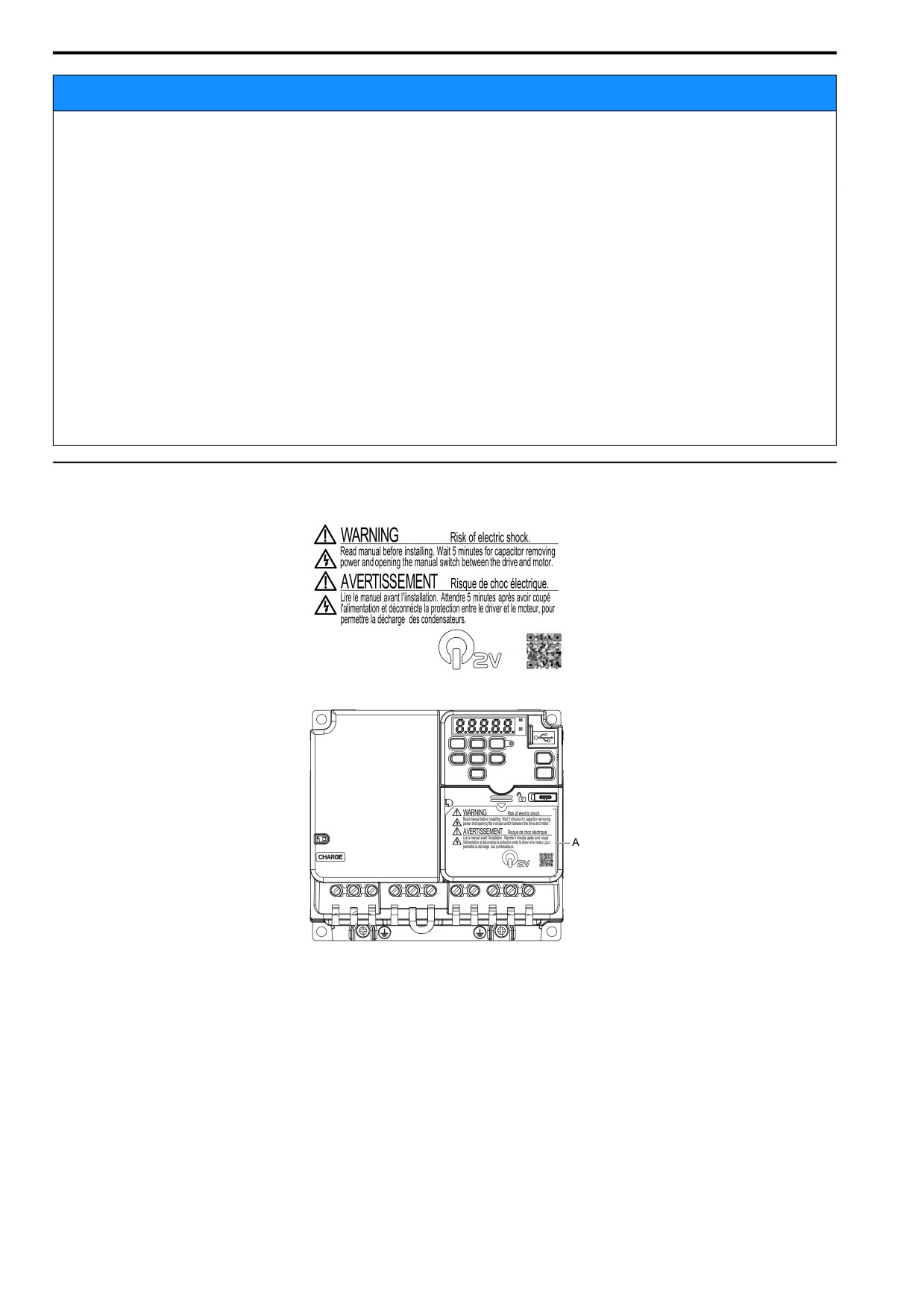
◆ Warning Label Content and Location
The drive warning label is in the location shown in Figure i.1. Use the drive as specified by this information.
A - Warning label
Figure i.1 Warning Label Content and Location
16

i.2
Legal Information
i.2
Legal Information
◆ Exclusion of Liability
• This product is not designed and manufactured for use in life-support machines or systems.
• Contact your sales representative if you are considering the application of this product for special purposes,
such as machines or systems used for passenger cars, medicine, airplanes and aerospace, nuclear power, electric
power, or undersea relaying.
WARNING
Injury to Personnel
When you use this product in applications where its failure could cause the loss of human life, a
serious accident, or physical injury, you must install applicable safety devices.
If you do not correctly install safety devices, it can cause serious injury or death.
◆ About Registered Trademarks
• CANopen is a registered trademark of CAN in Automation (CIA).
• CC-Link is a registered trademark of CC-Link Partner Association.
• DeviceNet is a registered trademark of Open DeviceNet Vendor Association, Inc. (ODVA).
• EtherCAT is a registered trademark of Beckhoff Automation GmbH.
• EtherNet/IP is a registered trademark of Open DeviceNet Vendor Association, Inc. (ODVA).
• LonWorks and LonTalk are registered trademarks of Echelon Corporation.
• MECHATROLINK-I, MECHATROLINK-II, and MECHATROLINK-III are registered trademarks of
MECHATROLINK Members Association (MMA).
• Modbus is a registered trademark of Schneider Electric SA.
• PROFIBUS-DP and PROFINET are registered trademarks of PROFIBUS International.
• Other company names and product names in this document are trademarks or registered trademarks of the
respective companies.
17
1
Receiving
This chapter gives information about the different drive models and features, and how to
examine the drive when you receive it.
1.1
Model Number and Nameplate Check
20
1.2
Features and Advantages of Control Methods
23
19
1.1 Model Number and Nameplate Check
1.1
Model Number and Nameplate Check
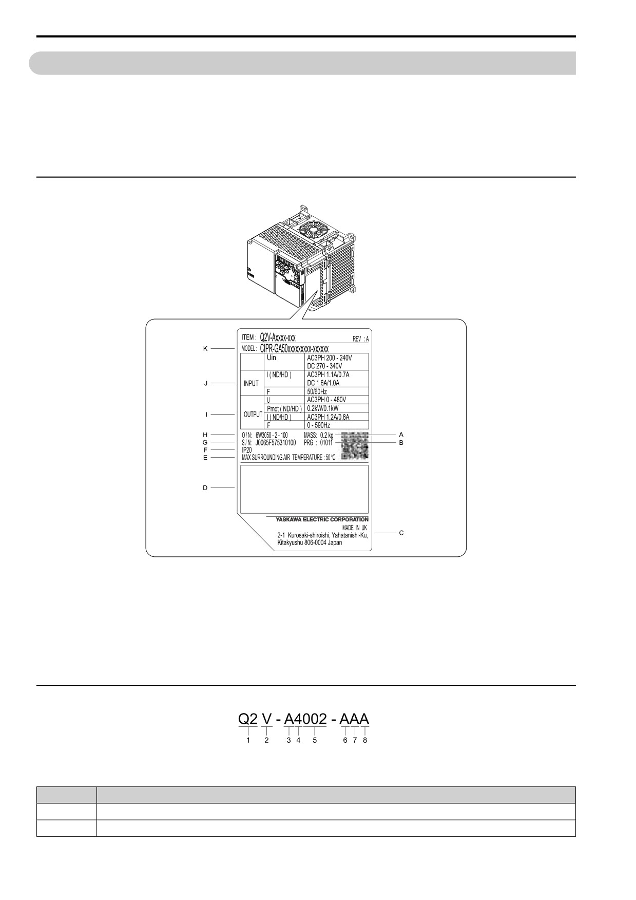
Please examine these items after you receive the drive:
• Examine the drive for damage. Immediately contact the shipping company if the drive is damaged. The
warranty does not cover damage from shipping.
• Examine the drive model number to make sure that you received the correct model. Examine the model number
in the “MODEL” section of the drive nameplate to make sure that you received the correct model.
• Contact your supplier if you receive the incorrect drive model or if the drive does not operate correctly.
◆ Nameplate
A - Mass
G - Product number
B - Drive software version
H - Serial number
C - The address of the head office of the
I - Output specifications
manufacturer
J - Input specifications
D - Accreditation standards
K - Drive model
E - Ambient Temperature Setting
F - Protection design
Figure 1.1 Nameplate Information Example
◆ How to Read Model Numbers
Figure 1.2 Drive model
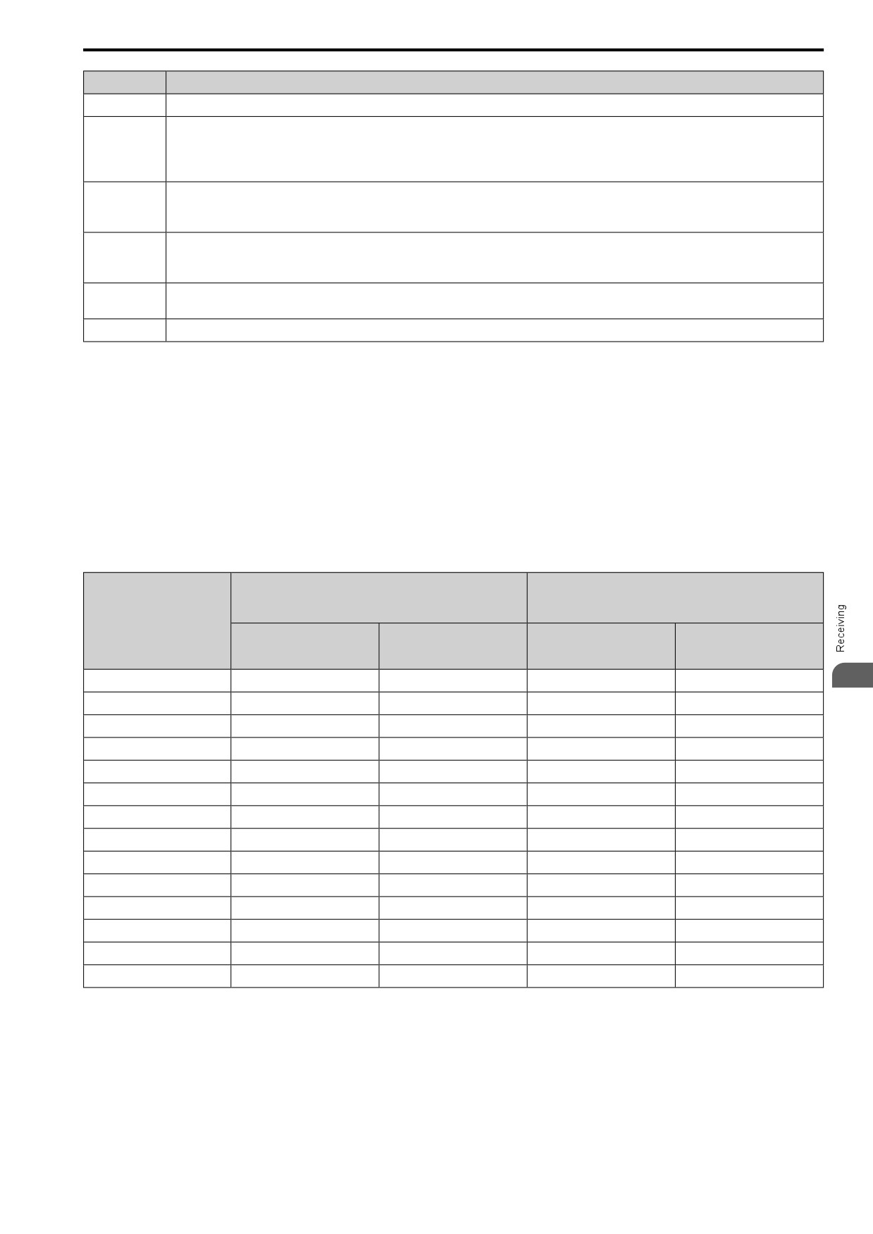
Table 1.1 Model Number Details
No.
Description
1
Q2 Series
2
V Series
20
1.1 Model Number and Nameplate Check
No.
Description
3
A: IP20 protection Class
4
Input power supply voltage
• B: Single-Phase AC 200 V Class
•
2: Three-Phase AC 200 V Class
•
4: Three-Phase AC 400 V Class
5
Rated output current
Note:
Refer to the rated output current list for more information.
6
EMC noise filter
• A: Built-in EMC filter
• B: Without built-in EMC filter
7
Coating Specification
• A: Standard
8
Version
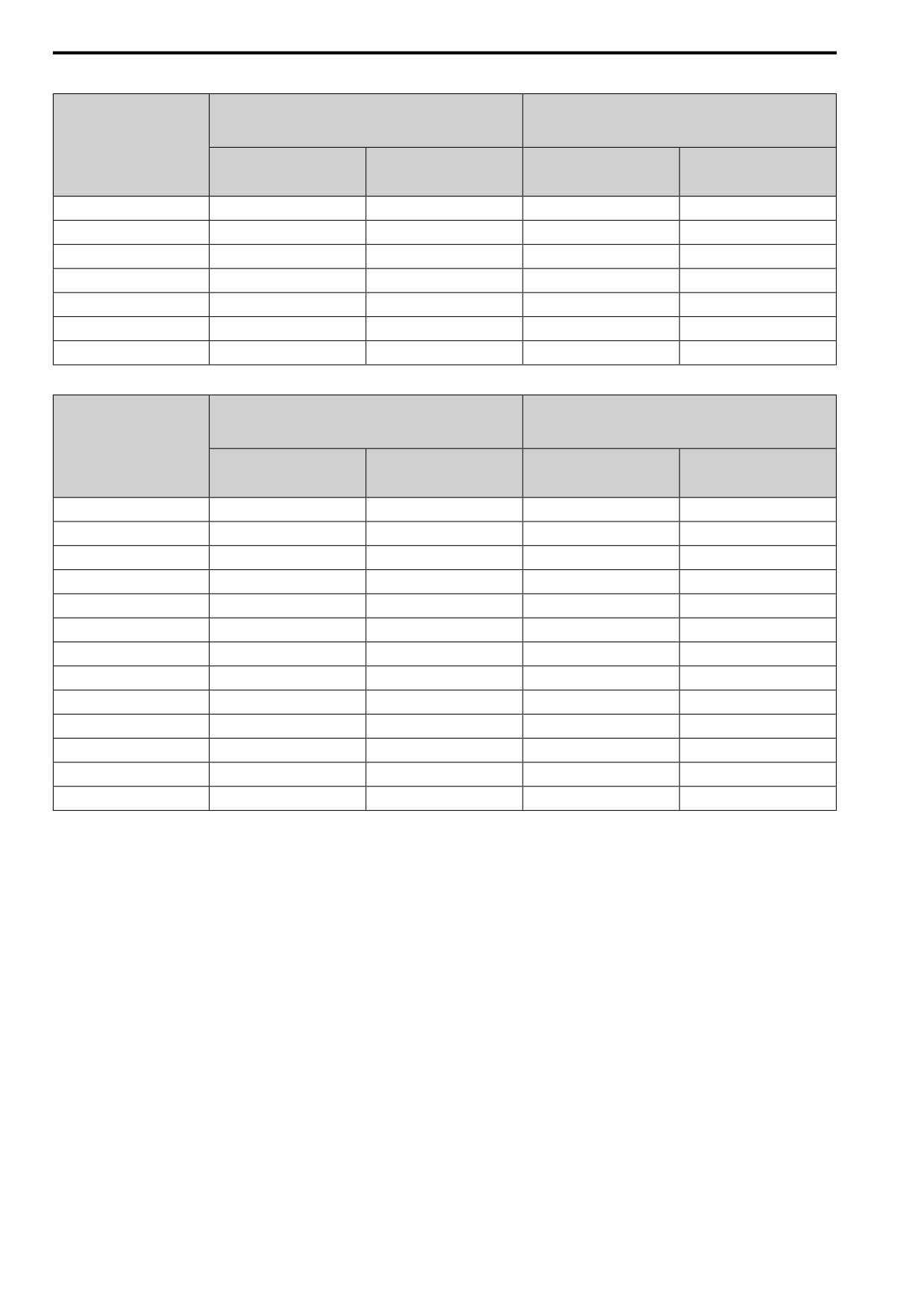
■ Rated Output Current
These output current values are applicable for drives that operate at standard specifications.
•
These output current values are applicable for drives that operate at standard specifications.
•
Derate the current in applications that:
- Increase the carrier frequency
- Have high ambient temperature
- Install drives side-by-side.
•
Use C6-01 [ND/HD Duty Selection] to select Normal Duty rating (ND) or Heavy Duty rating (HD).
Table 1.2 Three-Phase AC 200 V Class
HD Rating
ND Rating
[C6-01 = 0]
[C6-01 = 1]
(Default)
Model
Maximum Applicable Motor
Maximum Applicable Motor
Rated output current
Rated output current
Output
Output
A
A
kW
kW (HP)
2001
0.1
0.8
0.18
1.2
1
2002
0.25
1.6
0.37
1.9
2004
0.55
3.0
0.75
3.5
2006
1.1
5.0
1.1
6.0
2008
1.1
6.9
1.5
8.0
2010
1.5
8.0
2.2
9.6
2012
2.2
11.0
3.0
12.2
2018
3.0
17.6
3.7
17.5
2021
4.0
17.6
5.5
21.0
2030
5.5
25.0
7.5
30.0
2042
7.5
33.0
11.0
42.0
2056
11.0
47.0
15.0
56.0
2070
15.0
60.0
18.5
70.0
2082
18.5
75.0
22.0
82.0
21
1.1
Model Number and Nameplate Check
Table 1.3 Single-Phase AC 200 V Class
HD Rating
ND Rating
[C6-01 = 0]
[C6-01 = 1]
(Default)
Model
Maximum Applicable Motor
Maximum Applicable Motor
Rated output current
Rated output current
Output
Output
A
A
kW
kW
B001
0.1
0.8
0.18
1.2
B002
0.25
1.6
0.37
1.9
B004
0.55
3.0
0.75
3.5
B006
1.1
5.0
1.1
6.0
B010
1.5
8.0
2.2
9.6
B012
2.2
11.0
3.0
12.2
B018
4.0
17.6
-
-
Table 1.4 Three-Phase AC 400 V Class
HD Rating
ND Rating
[C6-01 = 0]
[C6-01 = 1]
(Default)
Model
Maximum Applicable Motor
Maximum Applicable Motor
Rated output current
Rated output current
Output
Output
A
A
kW
kW
4001
0.37
1.2
0.37
1.2
4002
0.55
1.8
0.75
2.1
4004
1.1
3.4
1.5
4.1
4005
1.5
4.8
2.2
5.4
4007
2.2
5.6
3.0
7.1
4009
3.0
7.3
4.0
8.9
4012
4.0
9.2
5.5
11.9
4018
5.5
14.8
7.5
17.5
4023
7.5
18.0
11.0
23.4
4031
11.0
24.0
15.0
31.0
4038
15.0
31.0
18.5
38.0
4044
18.5
39.0
22.0
44.0
4060
22.0
45.0
30.0
60.0
22
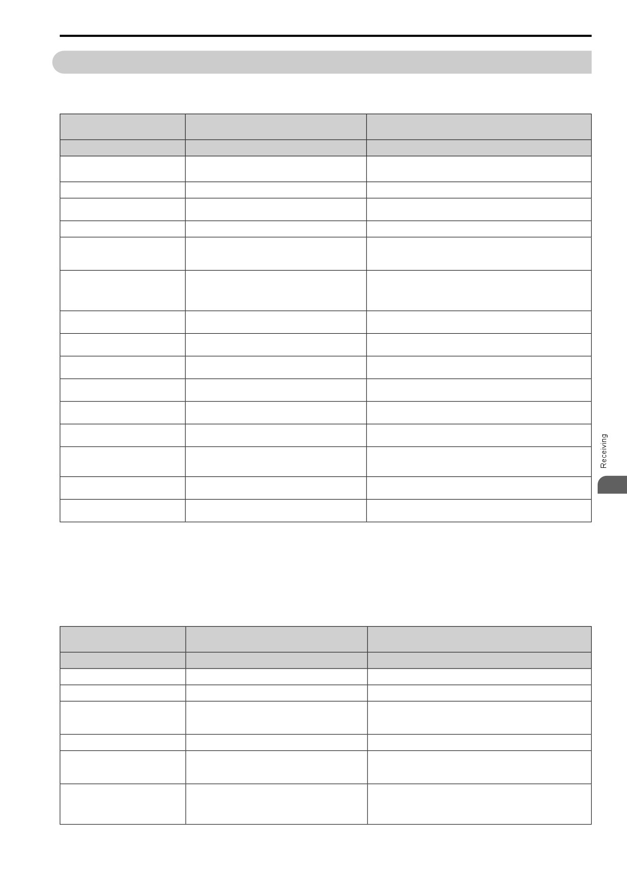
1.2 Features and Advantages of Control Methods
1.2
Features and Advantages of Control Methods
This drive has 5 available control methods from which you can select for different applications.
Table 1.5 Features and Advantages of V/f Control
Open Loop V/f Control
Control Method Selection
Notes
V/f Control)
Controlled Motor
Induction Motor
-
A1-02 = 0
Parameter Settings
-
(Default)
Basic Control
V/f
-
General-purpose variable speed control to connect more
Main Applications
-
than one motor to one drive.
Maximum Output Frequency
590 Hz
-
This is the range of variable control.
Speed Control Range
1:40
When you connect and operate motors in this mode, think about the
increase in motor temperature.
This is the motor torque that the drive can supply at low speed during
start-up and the related output frequency (rotation speed).
Starting Torque
150% / 3 Hz
You must think about drive capacity when a large quantity of torque is
necessary at low speed.
Rotational and Line-to-Line Resistance (usually not
Auto-Tuning *1
Automatically tunes electrical motor parameters.
necessary)
Controls maximum motor torque to prevent damage to machines and
Torque Limits
No
loads.
Immediately estimates (or detects) motor speed and direction when
Speed Search *1
Yes
coasting to a stop to quickly start-up the drive without stopping the motor.
Automatically adjusts the voltage that the drive applies to the motor to
Automatic Energy-saving Control *1
Yes
maximize motor efficiency for small and large loads.
Increases motor loss to let the motor decelerate faster than usual without a
High Slip Braking (HSB) *1
Yes
braking resistor. Motor characteristics have an effect on this function.
Compensates effects of the system inertia to increase the speed precision
Feed Forward Control
No
when the load changes.
Quickly and safely stops the motor during power loss and automatically
KEB Ride-Thru Function *1
Yes
starts operation at the previous speed when the drive applies power again
without coasting the motor.
Overexcitation Deceleration *1
Yes
Sets the V/f higher than the setting value during deceleration to increase
1
motor loss and decrease deceleration time.
Overvoltage Suppression Function *1
Yes
Adjusts speed during regeneration to prevent overvoltage.
*2
*1
Note these points when you use this function:
• When you can decouple the motor and machine for a test run, use Rotational Auto-Tuning. You must make adjustments to the
control in the range where there is no vibration in the machine after Rotational Auto-Tuning.
• Motor loss increases during overexcitation braking and high-slip braking. Use a maximum braking frequency of 5% ED and a
maximum braking time of 90 seconds. After you start high-slip braking, you cannot restart the motor until it stops. Use
overexcitation braking to decelerate over a shorter time at a pre-determined speed.
*2
Do not use this function with hoist application.
Table 1.6 Features and Advantages of OLV Control
Open Loop Vector
Control Method Selection
Notes
(OLVector)
Controlled Motor
Induction Motor
-
Parameter Settings
A1-02 = 2
-
Basic Control
Open Loop Current Vector Control
-
• General-purpose variable speed control
Main Applications
• Applications in which high performance is necessary
-
without machine encoders
Maximum Output Frequency
590 Hz
-
This is the range of variable control.
Speed Control Range
1:100
When you connect and operate motors in this mode, think about the
increase in motor temperature.
This is the motor torque that the drive can supply at low speed during
start-up and the related output frequency (rotation speed).
Starting Torque
150% / 1 Hz *1
You must think about drive capacity when a large quantity of torque is
necessary at low speed.
23
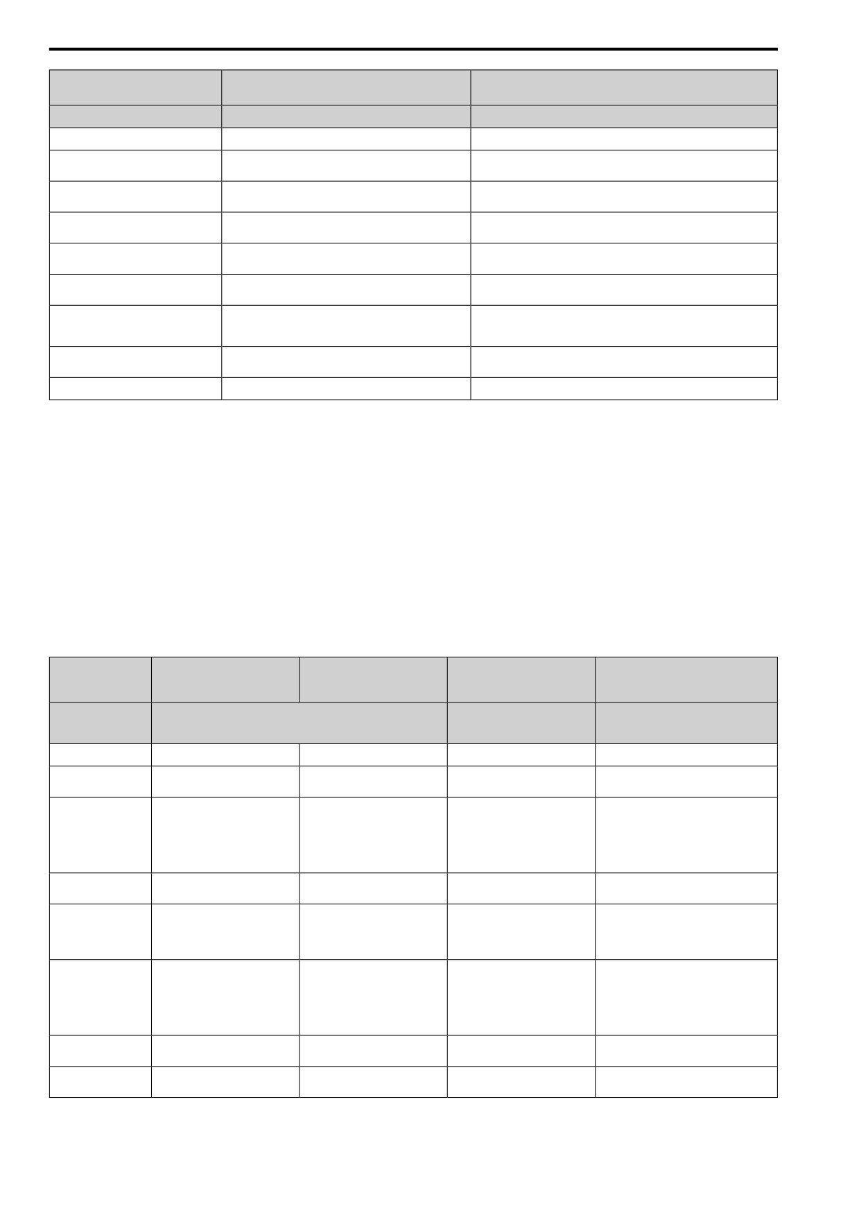
1.2 Features and Advantages of Control Methods
Open Loop Vector
Control Method Selection
Notes
(OLVector)
Controlled Motor
Induction Motor
-
Auto-Tuning *2
Rotational, Stationary, and Line-to-Line Resistance
Automatically tunes electrical motor parameters.
Controls maximum motor torque to prevent damage to machines and
Torque Limits *2
Yes
loads.
Immediately estimates (or detects) motor speed and direction when
Speed Search *2
Yes
coasting to a stop to quickly start-up the drive without stopping the motor.
Automatically adjusts the voltage that the drive applies to the motor to
Automatic Energy-saving Control *2
Yes
maximize motor efficiency for small and large loads.
Increases motor loss to let the motor decelerate faster than usual without a
High Slip Braking (HSB)
No
braking resistor. Motor characteristics have an effect on this function.
Compensates effects of the system inertia to increase the speed precision
Feed Forward Control
No
when the load changes.
Quickly and safely stops the motor during power loss and automatically
KEB Ride-Thru Function *2
Yes
starts operation at the previous speed when the drive applies power again
without coasting the motor.
Sets the V/f higher than the setting value during deceleration to increase
Overexcitation Deceleration *2
Yes
motor loss and decrease deceleration time.
Overvoltage Suppression Function *2 *3
Yes
Adjusts speed during regeneration to prevent overvoltage.
*1
Select the drive capacity accordingly.
*2
Note these points when you use this function:
• When you can decouple the motor and machine for a test run, use Rotational Auto-Tuning. You must make adjustments to the
control in the range where there is no vibration in the machine after Rotational Auto-Tuning.
• For vector control, use a 1:1 drive to motor ratio. You cannot use vector control when more than one motor is connected to one
drive. Select a drive capacity so that the motor rated current is 50% to 100% of the drive rated current. If the carrier frequency is
too high, the drive rated current is derated.
• Motor loss increases during overexcitation braking and high-slip braking. Use a maximum braking frequency of 5% ED and a
maximum braking time of 90 seconds. After you start high-slip braking, you cannot restart the motor until it stops. Use
overexcitation braking to decelerate over a shorter time at a pre-determined speed.
• Acceleration and deceleration have priority over torque limits in Open Loop Vector Control during acceleration and deceleration
(soft start changes). The drive will not operate until the speed is at the minimum frequency or the reverse direction of motor
rotation when the motor speed decreases because of torque limits during constant speed control. Set L7-07 = 2 [TrqLimit@Acc/
Decel = I-ctrl@Ac/Dec] to enable torque limits during acceleration/deceleration (for winding applications).
*3
Do not use this function with hoist application.
Table 1.7 Features and Advantages of OLV/PM, AOLV/PM, and EZOLV Control
PM Open Loop Vector
PM Advanced Open Loop
Control Method
EZ Open Loop Vector Control
Control
Vector
Notes
Selection
(EZ Vector)
(PM OLVector)
(PM AOLVector)
Induction Motors/PM Motors/
Controlled Motor
PM Motor
SynRM (Synchronous
-
Reluctance Motors)
Parameter Settings
A1-02 = 5
A1-02 = 6
A1-02 = 8
-
PM Open Loop Vector Control (no
PM Open Loop Current Vector
Open Loop Current Vector
Basic Control
-
speed controller)
Control (with speed controller)
Control
• General-purpose variable speed
• General-purpose variable speed
control for PM motors
control for IPM motors
Low-speed torque applications
Main Applications
• Applications in which a high
-
• Applications in which high-
level of responsiveness and
Example: Fans and pumps
precision speed control and
accurate speed control are not
torque limits are necessary.
necessary.
Maximum Output
590 Hz
270 Hz
120 Hz
-
Frequency
This is the range of variable control.
1:10
Speed Control Range
1:10
1:10
When you connect and operate motors in
1:100 *1 *2
this mode, think about the increase in
motor temperature.
This is the motor torque that the drive can
supply at low speed during start-up and the
100% / 5% speed
related output frequency (rotation speed).
Starting Torque
100% / 5% speed
100% / 10% speed
100% / 0 min-1 *1
You must think about drive capacity when
a large quantity of torque is necessary at
low speed.
Stationary, Stator Resistance,
Stationary, Stator Resistance,
Automatically tunes electrical motor
Auto-Tuning *4
Line-to-Line Resistance
Rotational
Rotational
parameters.
Controls maximum motor torque to
Torque Limits *4
No
Yes
Yes
prevent damage to machines and loads.
24
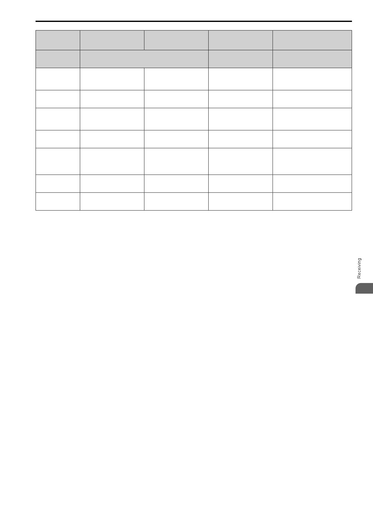
1.2 Features and Advantages of Control Methods
PM Open Loop Vector
PM Advanced Open Loop
Control Method
EZ Open Loop Vector Control
Control
Vector
Notes
Selection
(EZ Vector)
(PM OLVector)
(PM AOLVector)
Induction Motors/PM Motors/
Controlled Motor
PM Motor
SynRM (Synchronous
-
Reluctance Motors)
Immediately estimates (or detects) motor
Yes (Although NOT operation in
speed and direction when coasting to a
Speed Search *4
Yes
Yes
the reverse direction of the Run
stop to quickly start-up the drive without
command)
stopping the motor.
Automatically adjusts the voltage that the
Automatic Energy-
No
Yes (IPM motors only)
Yes
drive applies to the motor to maximize
saving Control *4
motor efficiency for small and large loads.
Increases motor loss to let the motor
High Slip Braking
No (induction motor-specific
No (induction motor-specific
decelerate faster than usual without a
No
(HSB)
function)
function)
braking resistor. Motor characteristics have
an effect on this function.
Compensates effects of the system inertia
Feed Forward Control
No
Yes
No
to increase the speed precision when the
*4
load changes.
Quickly and safely stops the motor during
power loss and automatically starts
KEB Ride-Thru
Yes
Yes
Yes
operation at the previous speed when the
Function *4
drive applies power again without coasting
the motor.
Sets the V/f higher than the setting value
Overexcitation
No (induction motor-specific
No (induction motor-specific
No
during deceleration to increase motor loss
Deceleration
function)
function)
and decrease deceleration time.
Overvoltage
Adjusts speed during regeneration to
Suppression Function
Yes
Yes
Yes
prevent overvoltage.
*4 *5
*1
Enabled when n8-57 = 1 [High-Freq Injection = Enabled].
*2
Rotational Auto-Tuning is necessary.
*3
Select the drive capacity accordingly.
*4
Note these points when you use this function:
• When you can decouple the motor and machine for a test run, use Rotational Auto-Tuning. You must make adjustments to the
control in the range where there is no vibration in the machine after Rotational Auto-Tuning.
• For vector control, use a 1:1 drive to motor ratio. You cannot use vector control when more than one motor is connected to one
drive. Select a drive capacity so that the motor rated current is 50% to 100% of the drive rated current. If the carrier frequency is
too high, the drive rated current is derated.
*5
Do not use this function with hoist application.
1
25
1.2 Features and Advantages of Control Methods
26
2
Mechanical Installation
This chapter gives information about the correct environment or space to install the drive.
2.1
Safety Precautions
28
2.2
Installation Environment
29
2.3
Installation Position and Distance
30
2.4
Moving the Drive
32
2.5
Removing/Reattaching Covers
33
2.6
Remove and Reattach the Keypad
35
2.7
Install the Keypad to a Control Panel or Another Device
36
2.8
Installation Methods
37
27
2.1 Safety Precautions
2.1
Safety Precautions
WARNING
Electrical Shock Hazard
Only let approved personnel install, wire, maintain, examine, replace parts, and repair the drive.
If personnel are not approved, it can cause serious injury or death.
Do not modify the drive body or drive circuitry.
Modifications to drive body and circuitry can cause serious injury or death, will cause damage to the drive, and
will void the warranty. The manufacturer is not responsible for modifications of the product made by the user.
Fire Hazard
Do not put flammable or combustible materials on top of the drive and do not install the drive
near flammable or combustible materials. Attach the drive to metal or other noncombustible
material.
Flammable and combustible materials can start a fire and cause serious injury or death.
When you install the drive in an enclosure, use a cooling fan or cooler to decrease the
temperature around the drive. Make sure that the intake air temperature to the drive is 50 °C (122
°F) or less for IP20/UL Open Type drives, and 40 °C (104 °F) or less for IP20/UL Type 1 drives.
If the air temperature is too hot, the drive can become too hot and cause a fire and serious injury or death.
CAUTION
Crush Hazard
Tighten terminal cover screws and hold the case safely when you move the drive.
If the drive or covers fall, it can cause moderate injury.
NOTICE
Do not let unwanted objects, for example metal shavings or wire clippings, fall into the drive
during drive installation. Put a temporary cover over the drive during installation. Remove the
temporary cover before start-up.
Unwanted objects inside of the drive can cause damage to the drive.
Obey correct electrostatic discharge (ESD) procedures when you touch the drive.
Incorrect ESD procedures can cause damage to the drive circuitry.
Install vibration-proof rubber on the base of the motor or use the frequency jump function in the
drive to prevent specific frequencies that vibrate the motor.
Motor or system resonant vibration can occur in fixed speed machines that are converted to variable speed. Too
much vibration can cause damage to equipment.
You can use the drive with an explosion-proof motor, but the drive is not explosion-proof. Install
the drive only in the environment shown on the nameplate.
If you install the drive in a dangerous environment, it can cause damage to the drive.
Do not lift the drive with the covers removed.
If the drive does not have covers, you can easily cause damage to the internal parts of the drive.
28
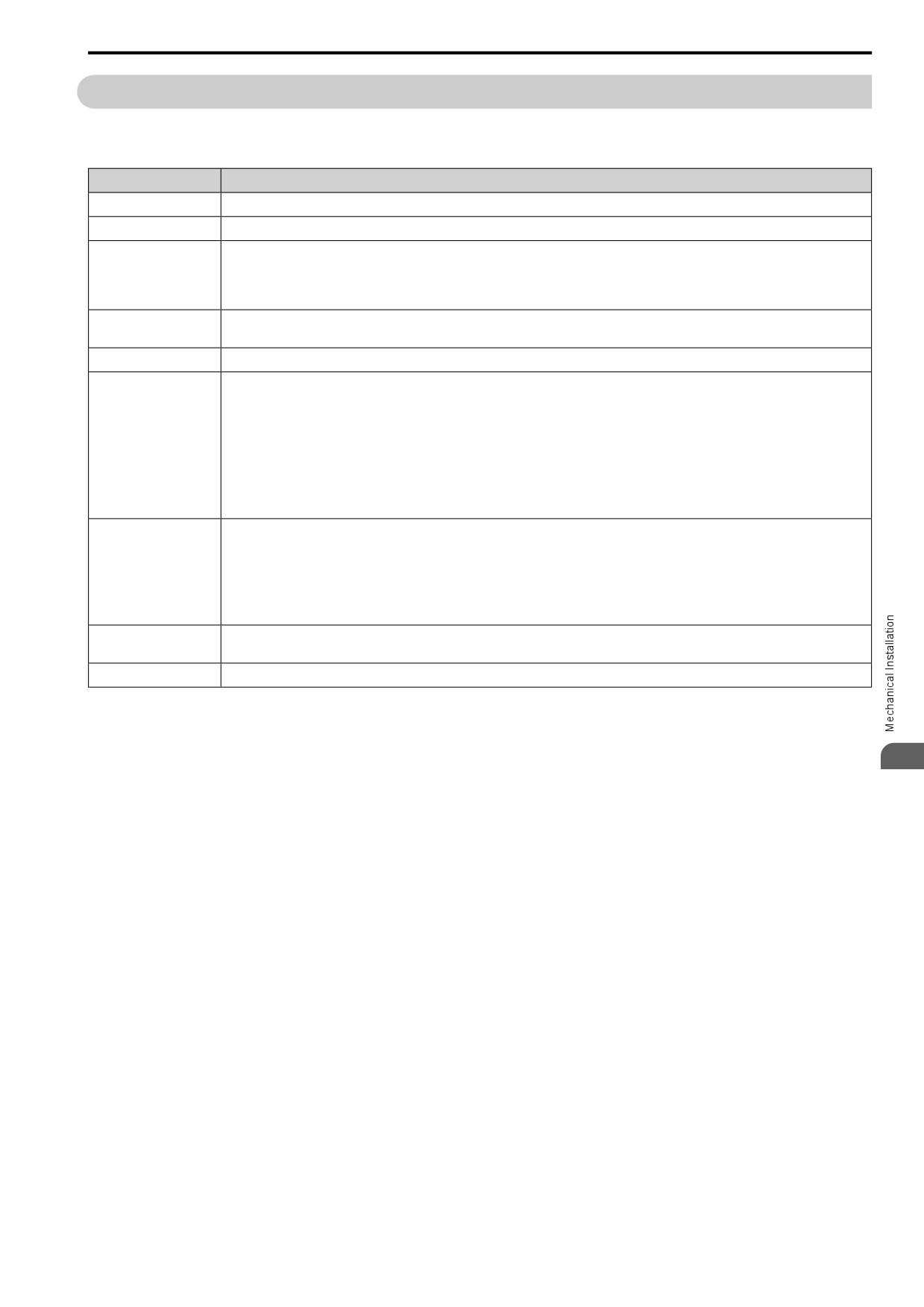
2.2 Installation Environment
2.2
Installation Environment
The installation environment is important for the lifespan of the product and to make sure that the drive
performance is correct. Make sure that the installation environment agrees with these specifications.
Environment
Conditions
Area of Use
Indoors
Power Supply
Overvoltage Category III (IEC60664)
IP20/UL Open Type: -10 °C to +50 °C (14 °F to 122 °F)
Ambient Temperature
IP20/UL Type 1: -10 °C to +40 °C (14 °F to 104 °F)
Setting
• When installing the drive in an enclosure, use a cooling fan or air conditioner to keep the internal air temperature in the permitted range.
• Do not let the drive freeze.
95%RH or less
Humidity
Do not let condensation form on the drive.
Storage Temperature
-20 °C to +70 °C (-4 °F to +158 °F) (short-term temperature during transportation)
Pollution degree 2 or less (IEC 60664-1)
Install the drive in an area without:
• Oil mist, corrosive or flammable gas, or dust
• Metal powder, oil, water, or other unwanted materials
Surrounding Area
• Radioactive or flammable materials.
• Harmful gas or fluids
• Salt
• Direct sunlight
Keep wood and other flammable materials away from the drive.
1000 m (3281 ft) Maximum
Note:
Derate the output current by 1% for each 100 m (328 ft) to install the drive in altitudes between 1000 to 4000 m (3281 to 13123 ft).
Altitude
It is not necessary to derate the rated voltage in these conditions:
• Installing the drive at 2000 m (6562 ft) or lower
• Installing the drive between 2000 to 4000 m (6562 to 13123 ft) and grounding the neutral point on the power supply.
Contact the manufacturer or your nearest sales representative when not grounding the neutral point.
•
10 Hz to 20 Hz: 1 G (9.8 m/s2, 32.15 ft/s2)
Vibration
•
20 Hz to 55 Hz: 0.6 G (5.9 m/s2, 19.36 ft/s2)
Installation Orientation
Install the drive vertically for sufficient airflow to cool the drive.
NOTICE: Do not put drive peripheral devices, transformers, or other electronics near the drive. Shield the drive from electrical
interference if components must be near the drive. Components near the drive can cause incorrect drive operation from
electrical interference.
NOTICE: Do not let unwanted objects, for example metal shavings or wire clippings, fall into the drive during drive installation.
2
Put a temporary cover over the drive during installation. Remove the temporary cover before start-up. Unwanted objects inside
of the drive can cause damage to the drive.
29
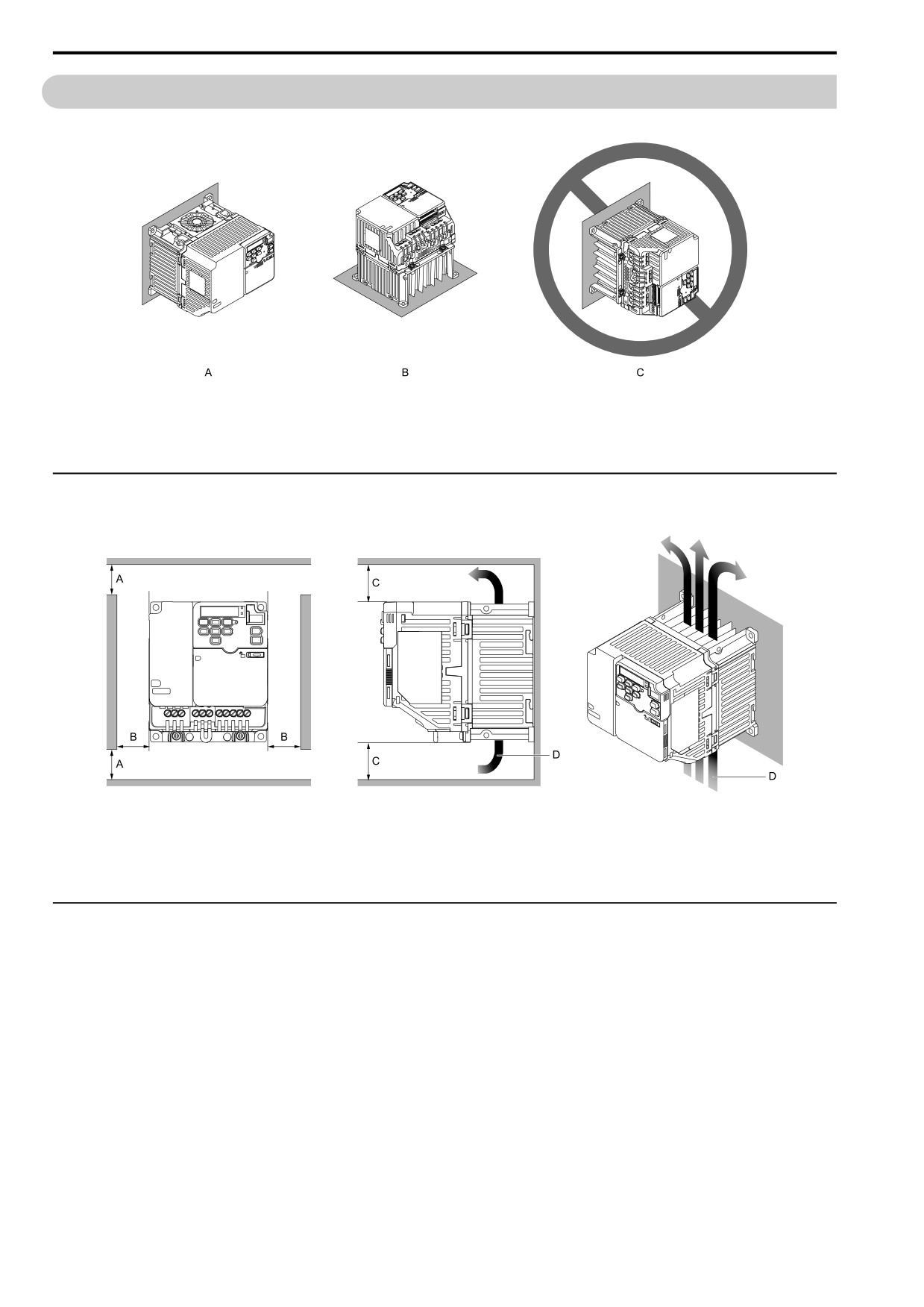
2.3 Installation Position and Distance
2.3
Installation Position and Distance
Install the drive vertically for sufficient airflow to cool the drive.
A - Vertical installation
C - Rotated installation
B - Horizontal installation
Figure 2.1 Installation Orientation
◆ Single Drive Installation
Use the clearances specified to install the drive. Make sure that there is sufficient space for wiring and airflow.
A - 50 mm (2 in) minimum between upper and lower
C - 100 mm (3.94 in) minimum above and below
openings
D - Airflow direction
B - 30 mm (1.18 in) minimum on each side
Figure 2.2 Installation Distances for One Drive
◆ Install Drives Side-by-Side
When you install drives side-by-side, set to L8-35 = 1 [Installation Selection = Side-by-Side Mounting].
Refer to Derating Depending on Ambient Temperature on page 303 and set derating depending on ambient
temperature.
30
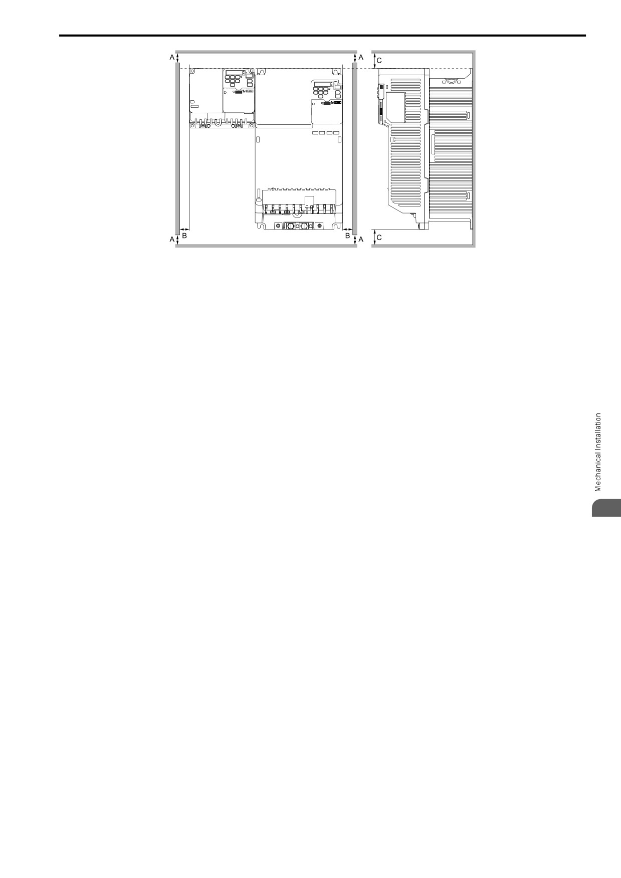
2.3 Installation Position and Distance
A - 50 mm (1.97 in) minimum between upper and
C - 100 mm (3.94 in) minimum above and below
lower openings
B - 30 mm (1.18 in) minimum on each side
Figure 2.3 Installation Distances for More than One Drive (Side-by-Side)
Note:
When you replace the cooling fans, align the tops of drives that have different dimensions. You can easily replace the cooling fan.
2
31
2.4 Moving the Drive
2.4
Moving the Drive
Obey local laws and regulations when moving and installing this product.
CAUTION! Sudden Movement Hazard. Do not hold the drive by the keypad or front cover. Tighten the screws correctly before
moving the drive. Failure to obey can cause minor to moderate injury.
32
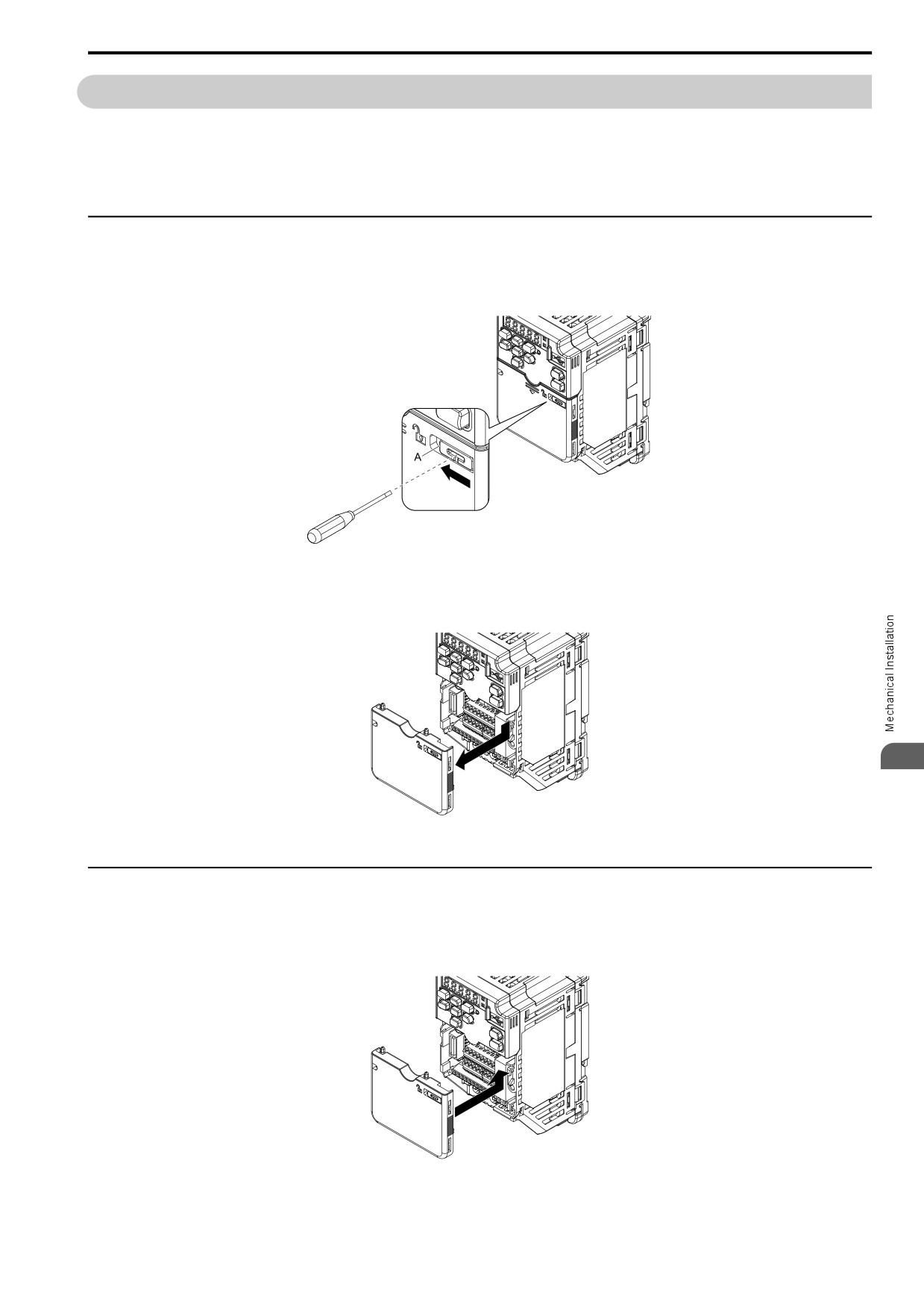
2.5 Removing/Reattaching Covers
2.5
Removing/Reattaching Covers
DANGER! Electrical Shock Hazard. Do not examine, connect, or disconnect wiring on an energized drive. Before servicing,
disconnect all power to the equipment and wait for the time specified on the warning label at a minimum. The internal capacitor
stays charged after the drive is de-energized. The charge indicator LED extinguishes when the DC bus voltage decreases
below 50 Vdc. When all indicators are OFF, measure for dangerous voltages to make sure that the drive is safe. If you do work
on the drive when it is energized, it will cause serious injury or death from electrical shock. The drive has internal capacitors that
stay charged after you de-energize the drive.
◆ Remove the Front Cover
1. Use a slotted screwdriver to unlock the front cover of the drive.
Use a slotted screwdriver with a tip width of 2.5 mm (0.1 in) or less and a thickness of 0.4 mm (0.02 in) or
less.
A - Front Cover Lock
Figure 2.4 Unlocking
2. Slide the front cover down and remove it from the drive.
2
Figure 2.5 Remove the Front Cover
◆ Reattach the Front Cover
1. Reverse the steps to reattach the cover.
Note:
Make sure that you do not pinch wires or signal lines between the front cover and the drive before you reattach the cover.
Figure 2.6 Reattach the Front Cover
33
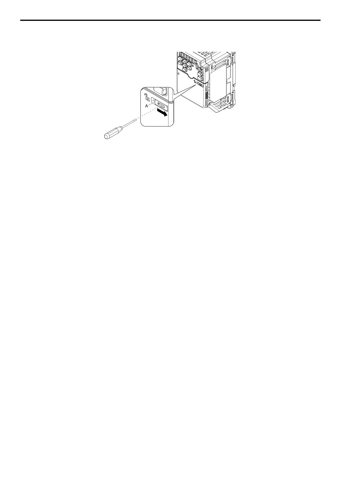
2.5 Removing/Reattaching Covers
2. Use a slotted screwdriver to lock the front cover of the drive.
Use a slotted screwdriver with a tip width of 2.5 mm (0.1 in) or less and a thickness of 0.4 mm (0.02 in) or
less.
A - Front Cover Lock
Figure 2.7 Locking the Front Cover
34
2.6 Remove and Reattach the Keypad
2.6
Remove and Reattach the Keypad
◆ Remove the Keypad
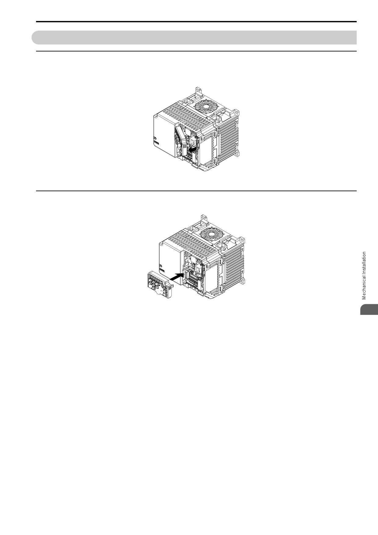
Remove the front cover.
Push on the tab on the right side of the keypad, then pull the keypad forward to remove it from the drive.
Figure 2.8 Remove the Keypad
◆ Reattach the Keypad
Push in the keypad from the front until the hooks click into place.
Figure 2.9 Reattach the Keypad
2
Attach the front cover.
35
2.7 Install the Keypad to a Control Panel or Another Device
2.7
Install the Keypad to a Control Panel or Another Device
You can remove the keypad from the drive and connect it to a remote control extension cable to make operation
easier when you cannot access the drive. You can operate a drive that is in a control panel without opening or
closing the control panel door. To order optional accessories, contact the manufacturer or your nearest sales
representative.
Name
Model
Intended Use
1 m: WV001
To connect the keypad and drive.
Extension Cable
3 m: WV003
This option is an RJ-45, 8-pin straight-through UTP CAT5e cable.
Installation Support Set A
900-192-933-001
To attach the keypad to the control panel. This option uses screws.
To attach the keypad to the control panel. This option uses nut clamps.
Installation Support Set B
900-192-933-002
Use this option when weld studs are located in the control panel.
36
2.8 Installation Methods
2.8
Installation Methods
The drive installation methods include standard installation and external heatsink installation.
◆ Standard Installation
Refer to Drive Exterior and Mounting Dimensions on page 307 for more information about external dimensions.
◆ External Heatsink
The optional External Heatsink Installation Kit will let you install the drive with the heatsink external to the
enclosure panel.
This table shows the model number for the attachment. Contact the manufacturer or your nearest sales
representative to order mounting brackets and mounting hardware.
Table 2.1 External Heatsink Installation Kit
Drive Model
Model
Drive Model
Model
2001
B006
ZPSA-GA50V2-2
ZPSA-GA50V1-1
2002
B010
ZPSA-GA50V2-3
2004
ZPSA-GA50V1-2
B012
ZPSA-GA50V3-1
2006
ZPSA-GA50V1-3
B018
ZPSA-GA50V4-1
2008
4001
ZPSA-GA50V2-1
2010
ZPSA-GA50V2-3
4002
ZPSA-GA50V2-2
2012
4004
2018
4005
ZPSA-GA50V3-1
2021
4007
ZPSA-GA50V2-3
2030
4009
ZPSA-GA50V5-1
2042
4012
ZPSA-GA50V3-1
2056
ZPSA-GA50V6-1
4018
ZPSA-GA50V5-1
2070
4023
ZPSA-GA50V7-1
2082
4031
ZPSA-GA50V6-1
B001
4038
2
ZPSA-GA50V1-1
B002
4044
ZPSA-GA50V8-1
B004
ZPSA-GA50V1-2
4060
37
3
Electrical Installation
This chapter gives how to wire the control circuit terminals, motor, and power supply of the
drive.
3.1
Safety Precautions
40
3.2
Standard Connection Diagram
42
3.3
Main Circuit Wiring
45
3.4
Main Circuit Terminal Block Wiring Procedure
71
3.5
Control Circuit Wiring
74
3.6
Control I/O Connections
81
3.7
Connect the Drive to a PC
84
3.8
External Interlock
85
3.9
Braking Resistor Installation
86
3.10
Drive Wiring Protection
88
3.11
Dynamic Braking Option, Motor Protection
89
3.12
Improve the Power Factor
91
3.13
Prevent Switching Surge
92
3.14
Decrease Noise
93
3.15
Protect the Drive during Failures
95
3.16
Wiring Checklist
97
3.17
Motor Application Precautions
99
39
3.1 Safety Precautions
3.1
Safety Precautions
DANGER
Electrical Shock Hazard
Do not examine, connect, or disconnect wiring on an energized drive. Before servicing,
disconnect all power to the equipment and wait for the time specified on the warning label at a
minimum. The internal capacitor stays charged after the drive is de-energized. The charge
indicator LED extinguishes when the DC bus voltage decreases below 50 Vdc. When all
indicators are OFF, measure for dangerous voltages to make sure that the drive is safe.
If you do work on the drive when it is energized, it will cause serious injury or death from electrical shock. The
drive has internal capacitors that stay charged after you de-energize the drive.
WARNING
Electrical Shock Hazard
Do not operate the drive when covers are missing. Replace covers and shields before you
operate the drive. Use the drive only as specified by the instructions.
Some figures in this section include drives without covers or safety shields to more clearly show the inside of the
drive. If covers or safety shields are missing from the drive, it can cause serous injury or death.
Ground the neutral point on the power supply of the drive to comply with the EMC Directive
before you turn on the EMC filter or if there is high resistance grounding.
If the EMC filter is switched ON without the neutral point being grounded or if there is high resistance
grounding, it can cause death or serious injury.
Make sure that the protective ground wire conforms to technical standards and local safety
regulations. The IEC/EN 61800-5-1:2007 standard specifies that you must wire the power supply
to automatically de-energize when the protective ground wire disconnects. If you turn on the
internal EMC filter, the leakage current of the drive will be more than 3.5 mA. You can also
connect a protective ground wire that has a minimum cross-sectional area of 10 mm2 (copper
wire).
If you do not obey the standards and regulations, it can cause serious injury or death.
When there is a DC component in the protective earthing conductor, the drive can cause a
residual current. When a residual current operated protective or monitoring device prevents
direct or indirect contact, always use a type B Residual Current Monitor/Residual Current
Device (RCM/RCD) as specified by IEC/EN 60755.
If you do not use the correct RCM/RCD, it can cause serious injury or death.
Do not wear loose clothing or jewelry when you do work on the drive. Tighten loose clothing
and remove all metal objects, for example watches or rings.
Loose clothing can catch on the drive and jewelry can conduct electricity and cause serious injury or death.
Do not remove covers or touch circuit boards while the drive is energized.
If you touch the internal components of an energized drive, it can cause serious injury or death.
Only let approved personnel install, wire, maintain, examine, replace parts, and repair the drive.
If personnel are not approved, it can cause serious injury or death.
Do not modify the drive body or drive circuitry.
Modifications to drive body and circuitry can cause serious injury or death, will cause damage to the drive, and
will void the warranty. The manufacturer is not responsible for modifications of the product made by the user.
Fire Hazard
Tighten all terminal screws to the correct tightening torque.
Connections that are too loose or too tight can cause incorrect operation and damage to the drive. Incorrect
connections can also cause death or serious injury from fire.
Tighten screws at an angle in the specified range shown in this manual.
If you tighten the screws at an angle not in the specified range, you can have loose connections that can cause
damage to the terminal block or start a fire and cause serious injury or death.
40

3.1 Safety Precautions
WARNING
Do not use the main circuit power supply (Overvoltage Category III) at incorrect voltages.
Operate the drive in the specification range of the input voltage on the drive nameplate.
Voltages that are higher than the permitted nameplate tolerance can cause damage to the drive.
When you install a dynamic braking option, wire the components as specified by the wiring
diagrams.
Incorrect wiring can cause damage to braking components or serious injury or death.
NOTICE
Do not let unwanted objects, for example metal shavings or wire clippings, fall into the drive
during drive installation. Put a temporary cover over the drive during installation. Remove the
temporary cover before start-up.
Unwanted objects inside of the drive can cause damage to the drive.
Obey correct electrostatic discharge (ESD) procedures when you touch the drive.
Incorrect ESD procedures can cause damage to the drive circuitry.
Select a motor that is compatible with the load torque and speed range. When 100% continuous
torque is necessary at low speed, use an inverter-duty motor or vector-duty motor. When you
use a standard fan-cooled motor, decrease the motor torque in the low-speed range.
If you operate a standard fan-cooled motor at low speed and high torque, it will decrease the cooling effects and
can cause heat damage.
Obey the speed range specification of the motor as specified by the manufacturer. When you
must operate the motor outside of its specifications, contact the motor manufacturer.
If you continuously operate oil-lubricated motors outside of the manufacturer specifications, it can cause damage
to the motor bearings.
When the input voltage is 440 V or higher or the wiring distance is longer than 100 m (328 ft),
make sure that the motor insulation voltage is sufficient or use an inverter-duty motor or vector-
duty motor with reinforced insulation.
Motor winding and insulation failure can occur.
Before you connect a dynamic braking option to the drive, make sure that qualified personnel
read and obey the Braking Unit and Braking Resistor Unit Installation Manual
(TOBPC72060001).
If you do not read and obey the manual or if personnel are not qualified it can cause damage to the drive and
braking circuit.
3
Make sure that all connections are correct after you install the drive and connect peripheral
devices.
Incorrect connections can cause damage to the drive.
Note:
• Torque characteristics differ compared to operating the motor directly from line power. The user should have a full understanding of
the load torque characteristics for the application.
• The rated input current of submersible motors is higher than the rated input current of standard motors. Carefully select the correct
drive capacity. When the distance between the motor and drive is long, use a wire that can connect the motor to the drive without a
reduction in motor torque.
• Do not use unshielded wire for control wiring. Use shielded, twisted-pair wires and ground the shield to the ground terminal of the
drive. Unshielded wire can cause electrical interference and unsatisfactory system performance.
41
3.2 Standard Connection Diagram
3.2
Standard Connection Diagram
Wire the drive as specified by Figure 3.1.
WARNING! Sudden Movement Hazard. Set the MFDI parameters before you close control circuit switches. Incorrect Run/Stop
circuit sequence settings can cause serious injury or death from moving equipment.
WARNING! Sudden Movement Hazard. Correctly wire the start/stop and safety circuits before you energize the drive. If you
momentarily close a digital input terminal, it can start a drive that is programmed for 3-Wire control and cause serious injury or
death from moving equipment.
WARNING! Sudden Movement Hazard. When you use a 3-Wire sequence, set A1-03 = 3330 [Init Parameters = 3-Wire
Initialization] and make sure that b1-17 = 1 [RUN@PowerUp Selection = Disregard RUN] (default). If you do not correctly set
the drive parameters for 3-Wire operation before you energize the drive, the motor can suddenly rotate in reverse when you
energize the drive.
NOTICE: Fire Hazard. Install sufficient branch circuit short circuit protection as specified by applicable codes and this manual.
The drive is suited for circuits that supply not more than 31,000 RMS symmetrical amperes, 240 Vac maximum (200 V Class),
480 Vac maximum (400 V Class). Incorrect branch circuit short circuit protection can cause serious injury or death.
NOTICE: When the input voltage is 440 V or higher or the wiring distance is longer than 100 m (328 ft), make sure that the
motor insulation voltage is sufficient or use an inverter-duty motor or vector-duty motor with reinforced insulation. Motor winding
and insulation failure can occur.
NOTICE: Do not connect the AC control circuit ground to the drive enclosure. Failure to obey can cause incorrect control circuit
operation.
42
//////////////////////////////////////////