Q2V Driving Quality. Technical Manual (Item code: Q2V-Axxxx-xxx, 2020) - page 13
12.2 b: APPLICATION
■ b5-71: PID Fdbk 1/2 Selection
No.
Default
Name
Description
(Hex.)
(Range)
b5-71
PID Fdbk 1/2 Selection
V/f
OLV OLV/PM AOLV/PM EZOLV
0
(01E6)
Selects the feedback configuration for PID control.
(0, 1)
0 : Feedback 1
The drive does D control on the difference between the feedback value and the PID setpoint output through U5-01
[PID Feedback].
1 : Feedback 2
The drive does D control on the difference between the feedback value and the PID setpoint output through U5-05
[PID Diff.Feedbk].
■ b5-72: PID D-FF Mode
No.
Default
Name
Description
(Hex.)
(Range)
b5-72
PID D-FF Mode
V/f
OLV OLV/PM AOLV/PM EZOLV
0
(01E7)
Determines whether the D part is in the feedback path or used for feed forward control.
(0, 1)
0 : D=Fdback
The drive does D control on the feedback output through U5-06 [PID AdjustFeedback].
1 : D=FdFwd
The drive adds the frequency reference to the PID output. The drive does D control on the feedback output
through U5-06 [PID AdjustFeedback].
■ b5-02: Proportional Gain (P)
No.
Default
Name
Description
(Hex.)
(Range)
b5-02
Proportional Gain (P)
V/f
OLV OLV/PM AOLV/PM EZOLV
1.00
(01A6)
Sets the proportional gain (P) that is applied to PID input.
(0.00
- 25.00)
RUN
Larger values decrease errors, but can cause oscillations. Smaller values let too much offset between the setpoint
and feedback.
Set b5-02 = 0.00 to disable P control.
■ b5-03: Integral Time (I)
No.
Default
Name
Description
(Hex.)
(Range)
V/f
OLV OLV/PM AOLV/PM EZOLV
b5-03
Integral Time (I)
1.0 s
(01A7)
Sets the integral time (I) that is applied to PID input.
(0.0 - 360.0 s)
RUN
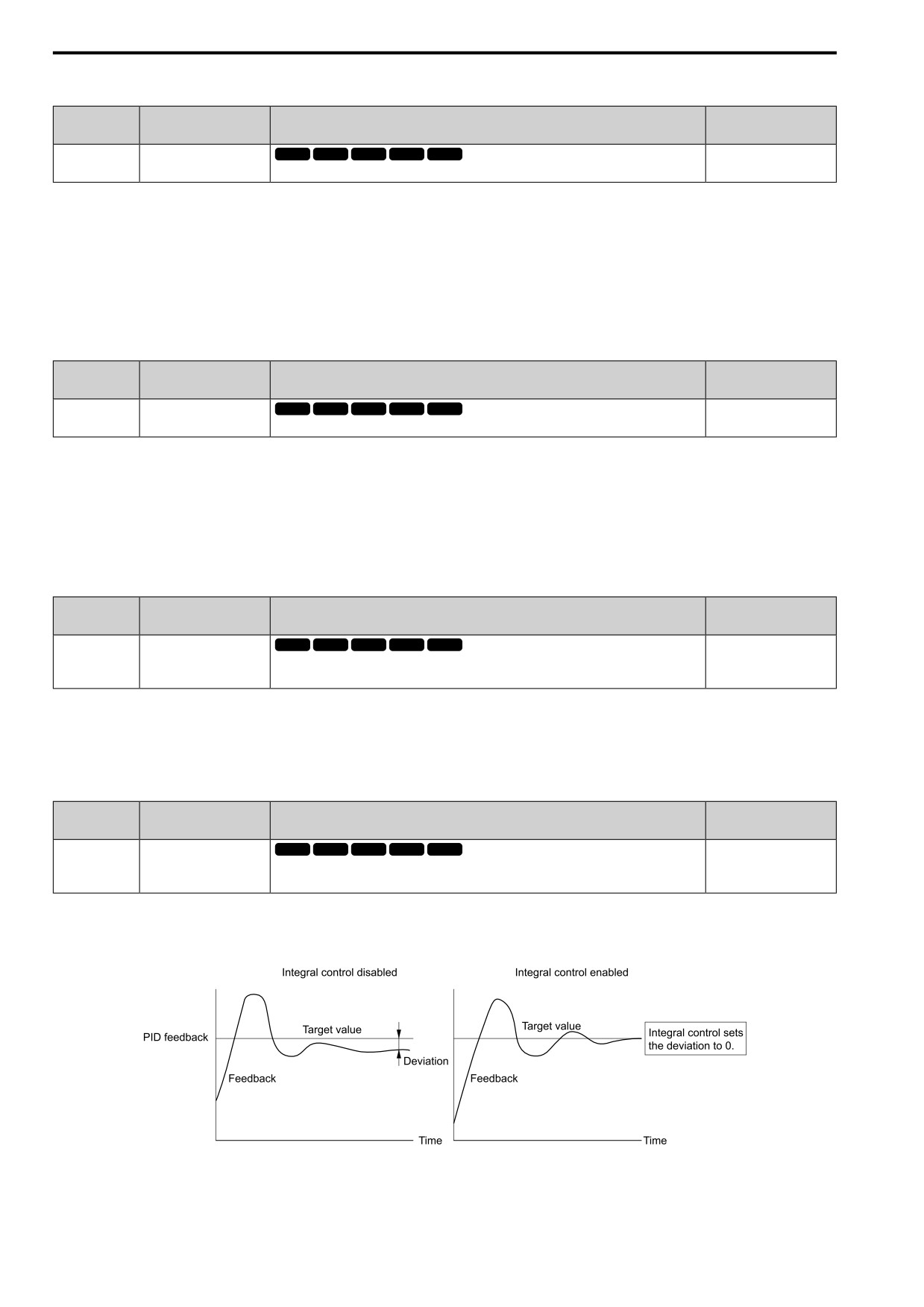
Set a short integral time in b5-03 to remove the offset more quickly. If the integral time is too short, overshoot or
oscillation can occur.
Set b5-03 = 0.00 to disable I control.
Figure 12.33 Integral Time and Deviation
472
12.2 b: APPLICATION
■ b5-04: Integral Limit
No.
Default
Name
Description
(Hex.)
(Range)
b5-04
Integral Limit
V/f
OLV OLV/PM AOLV/PM EZOLV
100.0%
(01A8)
Sets the upper limit for integral control (I) as a percentage of the Maximum Output Frequency.
(0.0
- 100.0%)
RUN
Applications with loads that quickly change will cause the output of the PID function to oscillate. Set this
parameter to a low value to prevent oscillation, mechanical loss, and motor speed loss.
■ b5-05: Derivative Time (D)
No.
Default
Name
Description
(Hex.)
(Range)
V/f
OLV OLV/PM AOLV/PM EZOLV
b5-05
Derivative Time (D)
0.00 s
(01A9)
Sets the derivative time (D) for PID control. This parameter adjusts system responsiveness.
(0.00 - 10.00 s)
RUN
When you increase the time setting, it will increase controller responsiveness, but it can also cause vibration.
When you decrease the time setting, it will suppress overshoot and decrease controller responsiveness.
Set b5-05 = 0.00 to disable D control.
■ b5-06: PID Output Limit
No.
Default
Name
Description
(Hex.)
(Range)
b5-06
PID Output Limit
V/f
OLV OLV/PM AOLV/PM EZOLV
100.0%
(01AA)
Sets the maximum possible output from the PID controller as a percentage of the Maximum
(0.0
- 100.0%)
Output Frequency.
RUN
■ b5-07: PID Offset Adjustment
No.
Default
Name
Description
(Hex.)
(Range)
V/f
OLV OLV/PM AOLV/PM EZOLV
b5-07
PID Offset Adjustment
0.0%
(01AB)
Sets the offset for the PID control output as a percentage of the Maximum Output Frequency.
(-100.0 - +100.0%)
RUN
■ b5-08: PID Primary Delay Time Constant
No.
Default
Name
Description
(Hex.)
(Range)
b5-08
PID Primary Delay Time
V/f
OLV OLV/PM AOLV/PM EZOLV
0.00 s
Constant
(01AC)
Sets the primary delay time constant for the PID control output. Usually it is not necessary to
(0.00 - 10.00 s)
change this setting.
RUN
Expert
Prevents resonance if there is a large quantity of mechanical friction or if rigidity is unsatisfactory. Set the value
larger than the resonant frequency cycle. A value that is too large will decrease drive responsiveness.
■ b5-09: PID Output Level Selection
No.
Default
Name
Description
(Hex.)
(Range)
V/f
OLV OLV/PM AOLV/PM EZOLV
b5-09
PID Output Level Selection
0
(01AD)
Sets the polarity of the PID output.
(0, 1)
Use this parameter in applications that decrease the drive output frequency when you increase the PID setpoint.
0 : Normal output
A positive PID input increases the PID output (direct acting).
1 : Reverse output
A positive PID input decreases the PID output (reverse acting).
12
473
12.2 b: APPLICATION
■ b5-10: PID Output Gain Setting
No.
Default
Name
Description
(Hex.)
(Range)
b5-10
PID Output Gain Setting
V/f
OLV OLV/PM AOLV/PM EZOLV
1.00
(01AE)
Sets the amount of gain to apply to the PID output.
(0.00
- 25.00)
RUN
Applies a gain to the PID output and can help when b5-01 = 1 [PID Enable = Enabled] and b5-72 = 0 [PID D-
FF Mode = D=Fdback].
■ b5-11: PID Output Reverse Selection
No.
Default
Name
Description
(Hex.)
(Range)
V/f
OLV OLV/PM AOLV/PM EZOLV
b5-11
PID Output Reverse
0
(01AF)
Selection
Sets the function that enables and disables reverse motor rotation for negative PID control output.
(0, 1)
This parameter is disabled when b5-01 = 1 [PID Enable = Enabled] and b5-72 = 0 [PID D-FF Mode = D=
Fdback]. There is no limit for PID output (PID output can be positive or negative).
0 : 0 lower limit
When PID output is negative, PID output is limited to 0 and drive output is shut off.
1 : Negative lower limit
When the PID output is negative, the motor will rotate in reverse. When b1-04 = 1 [Reverse Operation Selection
= Disabled], the lower limit is 0.
■ b5-12: Fdback Loss Select Mode
No.
Default
Name
Description
(Hex.)
(Range)
V/f
OLV OLV/PM AOLV/PM EZOLV
b5-12
Fdback Loss Select Mode
0
(01B0)
Sets the drive response to PID feedback loss/excess. Sets drive operation after the drive detects
(0 - 5)
PID feedback loss/excess.
0 : DO Only Always
The MFDO terminal set for PID Feedback Low or PID Feedback High [H2-01 to H2-03 = 3E, 3F] activates.
When the drive detects feedback loss/excess, the keypad will not show an alarm and the drive will continue
operation.
When the feedback signal is less than the level set in b5-13 [Fdback Loss Lvl] for longer than the time set in b5-
14 [Fdback Loss Time], the MFDO terminal set for PID Feedback Low activates.
When the feedback signal is more than the level set in b5-36 [PID HiHi Limit Level] for longer than the time set
in b5-37 [PID HiHi Time] the MFDO terminal set for PID Feedback High activates.
When the feedback value is not in the detection range, the drive resets the MFDO.
1 : AL+DO Always
The drive detects FbL [PID Feedback Loss] and FbH [Excessive PID Feedback]. The MFDO terminal set for
PID Feedback Low or PID Feedback High [H2-01 to H2-03 = 3E, 3F] activates. The output terminal set for
Alarm [H2-01 to H2-03 = 4] activates and the drive continues operation.
When the feedback signal is less than the level set in b5-13 for longer than the time set in b5-14, the MFDO
terminal set for PID Feedback Low activates.
When the feedback signal is more than the level set in b5-36 for longer than the time set in b5-37, the MFDO
terminal set for PID Feedback High activates.
When the feedback value is not in the detection range, the drive resets the MFDO.
2 : FLT+DO Always
The drive detects FbL and FbH. MFDO terminal NO-CM turns ON, NC-CM turns OFF, and the motor coasts to
stop.
When the feedback signal is less than the level set in b5-13 for the time set in b5-14, the drive detects FbL.
When the feedback signal is more than the level set in b5-36 for the time set in b5-37, the drive detects FbH.
3 : DO Only@PID Enable
The MFDO terminal set for PID Feedback Low or PID Feedback High activates. The keypad will not show an
alarm. The drive continues operation.
474
12.2 b: APPLICATION
When the MFDI terminal set to PID Disable [H1-xx = 6A] activates, the drive disables fault detection.
4 : AL+DO@PID Enable
The drive detects FbL and FbH. The MFDO terminal set for PID Feedback Low or PID Feedback High activates.
The output terminal set for Alarm [H2-01 to H2-03 = 4] activates and the drive continues operation.
When the MFDI terminal set to PID Disable [H1-xx = 6A] activates, the drive disables fault detection.
5 : FLT+DO@PID Enable
The drive detects FbL and FbH. MFDO terminal NO-CM turns ON, NC-CM turns OFF, and the drive coasts to
stop.
When the MFDI terminal set to PID Disable [H1-xx = 6A] activates, the drive disables fault detection.
■ b5-13: Fdback Loss Lvl
No.
Default
Name
Description
(Hex.)
(Range)
b5-13
Fdback Loss Lvl
V/f
OLV OLV/PM AOLV/PM EZOLV
0%
(01B1)
Sets the level that triggers PID Feedback Loss [FbL] detection as a percentage of the Maximum
(0 - 100%)
Output Frequency.
The drive detects PID Feedback Loss [FbL] when the feedback signal decreases to less than the level set in b5-13
for longer than the time set in b5-14 [Fdback Loss Time].
■ b5-14: Fdback Loss Time
No.
Default
Name
Description
(Hex.)
(Range)
b5-14
Fdback Loss Time
V/f
OLV OLV/PM AOLV/PM EZOLV
1.0 s
(01B2)
Sets the length of time that PID Feedback must be less than b5-13 [Fdback Loss Lvl] to detect
(0.0 - 25.5 s)
PID Feedback Loss [FbL].
■ b5-15: Sleep Start Level
No.
Default
Name
Description
(Hex.)
(Range)
b5-15
Sleep Start Level
V/f
OLV OLV/PM AOLV/PM EZOLV
Determined by A1-02
(01B3)
Sets the output level that triggers the PID Sleep function.
(0.0
- 590.0)
The drive goes into Sleep mode when the PID output or frequency reference is less than b5-15 for longer than the
time set to b5-16 [Sleep Delay Time]. The drive continues operation when the PID output or frequency reference
is more than b5-15 for longer than the time set to b5-16.
■ b5-16: Sleep Delay Time
No.
Default
Name
Description
(Hex.)
(Range)
b5-16
Sleep Delay Time
V/f
OLV OLV/PM AOLV/PM EZOLV
0.0 s
(01B4)
Sets a delay time to start or stop the PID Sleep function.
(0.0 - 25.5 s)
■ b5-17: PID Accel/Decel Time
No.
Default
Name
Description
(Hex.)
(Range)
b5-17
PID Accel/Decel Time
V/f
OLV OLV/PM AOLV/PM EZOLV
0.0 s
(01B5)
Raises or lowers the PID setpoint using the acceleration and deceleration times set to the drive.
(0.0 - 6000.0 s)
This is a soft-starter for the PID setpoint.
RUN
The drive usually uses the acceleration and deceleration times set in C1: ACCEL / DECEL, but when PID control
is enabled, the drive applies C1-xx after PID output. If you frequently change the PID setpoint, the drive
responsiveness decreases. When resonance with PID control causes hunting, overshoot, or undershoot, set b5-17
for longer acceleration and deceleration times.
Decrease C1-xx until hunting stops, then use b5-17 to check the acceleration and deceleration. To enable and
disable the setting in b5-17 through an MFDI terminal, set PID SS Cancel [H1-xx = 75].
12
475
12.2 b: APPLICATION
■ b5-18: b5-19 PID SP Selection
No.
Default
Name
Description
(Hex.)
(Range)
b5-18
b5-19 PID SP Selection
V/f
OLV OLV/PM AOLV/PM EZOLV
0
(01DC)
Sets the function that enables and disables b5-19 [PID Setpoint Value].
(0, 1)
0 : Disabled
The drive does not use the value set in b5-19 as the PID setpoint.
1 : Enabled
The drive uses the value set in b5-19 as the PID setpoint.
■ b5-19: PID Setpoint Value
No.
Default
Name
Description
(Hex.)
(Range)
b5-19
PID Setpoint Value
V/f
OLV OLV/PM AOLV/PM EZOLV
0.00%
(01DD)
Sets the PID setpoint when b5-18 = 1 [b5-19 PID SP Selection = Enabled].
(0.00
- 100.00%)
RUN
■ b5-20: PID Unit Selection
No.
Default
Name
Description
(Hex.)
(Range)
b5-20
PID Unit Selection
V/f
OLV OLV/PM AOLV/PM EZOLV
1
(01E2)
Sets the number of digits to set and show the PID setpoint.
(0 - 3)
Set the units for these parameters and monitors:
• b5-19 [PID Setpoint Value]
• b5-58 [PID Setpoint 2]
• b5-59 [PID Setpoint 3]
• b5-60 [PID Setpoint 4]
• U5-01 [PID Feedback]
• U5-04 [PID Setpoint]
• U5-99 [PID Setpoint Command]
0 : 0.01Hz units
The drive uses 0.01 Hz units.
1 : 0.01% units
The drive uses 0.01% units. Set the value as a percentage of E1-04 [Max Output Frequency].
2 : rpm
The drive uses 1 min-1 unit. Set E2-04, E4-04, or E5-04 [PM Mot Pole Count].
3 : User Units
The drive uses the units set in b5-38 [PID SP User Scale for Display] and b5-39 [PID SP User digits for Display]
to show the PID setpoint in U5-01, U5-04, U5-06 [PID Feedback, PID Setpoint, PID AdjustFeedbackk].
■ b5-34: PID Out Low Limit Level
No.
Default
Name
Description
(Hex.)
(Range)
V/f
OLV OLV/PM AOLV/PM EZOLV
b5-34
PID Out Low Limit Level
0.0%
(019F)
Sets the output lower limit for the PID control as a percentage of the Maximum Output
(-100.0 - +100.0%)
Frequency.
RUN
Use a lower limit to keep PID control output from dropping below a fixed level.
Set this parameter to 0.0% to disable this function.
476
12.2 b: APPLICATION
■ b5-35: PID In Hi Limit Level
No.
Default
Name
Description
(Hex.)
(Range)
b5-35
PID In Hi Limit Level
V/f
OLV OLV/PM AOLV/PM EZOLV
1000.0%
(01A0)
Sets the output upper limit for the PID control as a percentage of the Maximum Output
(0.0
- 1000.0%)
Frequency.
RUN
A large input value for PID control makes a high output. The drive applies this limit to the negative and positive
domains.
■ b5-36: PID HiHi Limit Level
No.
Default
Name
Description
(Hex.)
(Range)
V/f
OLV OLV/PM AOLV/PM EZOLV
b5-36
PID HiHi Limit Level
100%
(01A1)
Sets the level that triggers Excessive PID Feedback [FbH] as a percentage of the Maximum
(0 - 100%)
Output Frequency.
When the feedback signal increases to more than the level set in b5-36 for the time set in b5-37 [PID HiHi Time],
the drive will detect Excessive PID Feedback [FbH].
■ b5-37: PID HiHi Time
No.
Default
Name
Description
(Hex.)
(Range)
b5-37
PID HiHi Time
V/f
OLV OLV/PM AOLV/PM EZOLV
1.0 s
(01A2)
Sets the length of time that the PID feedback signal must be more than the level set in b5-36 [PID
(0.0 - 25.5 s)
HiHi Limit Level] to cause Excessive PID Feedback [FbH].
■ b5-38: PID SP User Scale for Display
No.
Default
Name
Description
(Hex.)
(Range)
b5-38
PID SP User Scale for
V/f
OLV OLV/PM AOLV/PM EZOLV
Determined by b5-20
Display
(01FE)
Sets the value that the drive sets or shows as the PID setpoint when at the maximum output
(1 - 60000)
frequency.
The drive uses this parameter and b5-39 [PID SP User digits for Display] together.
When b5-20 = 3 [PID Unit Selection = User Units], the drive applies user-set PID setpoint and display units to
these parameters and monitors:
• b5-19 [PID Setpoint Value]
• b5-58 [PID Setpoint 2]
• b5-59 [PID Setpoint 3]
• b5-60 [PID Setpoint 4]
• U5-01 [PID Feedback]
• U5-04 [PID Setpoint]
• U5-99 [PID Setpoint Command]
■ b5-39: PID SP User digits for Display
No.
Default
Name
Description
(Hex.)
(Range)
b5-39
PID SP User digits for
V/f
OLV OLV/PM AOLV/PM EZOLV
Determined by b5-20
Display
(01FF)
Sets the number of digits to set and show the PID setpoint.
(0 - 3)
The drive uses this parameter and b5-38 [PID SP User Scale for Display] together.
When b5-20 = 3 [PID Unit Selection = User Units], the drive applies user-set PID setpoint and display units to
these parameters and monitors:
• b5-19 [PID Setpoint Value]
• b5-58 [PID Setpoint 2]
• b5-59 [PID Setpoint 3]
12
• b5-60 [PID Setpoint 4]
• U5-01 [PID Feedback]
477
12.2 b: APPLICATION
• U5-04 [PID Setpoint]
• U5-99 [PID Setpoint Command]
0 : No Decimal Places
1 : 1 Decimal Place
2 : 2 decimal places
3 : 3 Decimal Places
■ b5-40: Fref Mon@PID
No.
Default
Name
Description
(Hex.)
(Range)
b5-40
Fref Mon@PID
V/f
OLV OLV/PM AOLV/PM EZOLV
0
(017F)
Sets the contents for monitor U1-01 [Frequency Reference] in PID control.
(0, 1)
0 : U1-01 with PID Output
Monitor U1-01 shows the frequency reference that was increased or decreased by the PID output.
1 : U1-01 without PID Output
Monitor U1-01 shows the actual frequency reference.
■ b5-47: PID Out Rev Operation Mode
No.
Default
Name
Description
(Hex.)
(Range)
b5-47
PID Out Rev Operation
V/f
OLV OLV/PM AOLV/PM EZOLV
1
Mode
(017D)
Sets reverse motor rotation when the PID control output is negative.
(0, 1)
This parameter is enabled when b5-01 = 1 [PID Enable = Enabled].
0 : Lower Limit is Zero
When PID output is negative, PID output is limited to 0 and drive output is shut off.
1 : Negative Output Accepted
When the PID output is negative, the motor will rotate in reverse.
■ b5-53: PID I Ramp Limit
No.
Default
Name
Description
(Hex.)
(Range)
b5-53
PID I Ramp Limit
V/f
OLV OLV/PM AOLV/PM EZOLV
0.0 Hz
(0B8F)
Sets the responsiveness of PID control when the PID feedback changes quickly.
(0.0 - 10.0 Hz)
RUN
Note:
• This parameter is disabled when set to 0.0 Hz.
• When b5-53 > 0.0 Hz and the drive enables the integrator ramp limit, the PID integrator value limit is the range set by the output
frequency ± b5-53.
• When the PID feedback changes quickly, gradually decrease the this parameter in 0.1 Hz increments to decrease the speed of the
response of PID control.
■ b5-54: PID Softstarter Selection
No.
Default
Name
Description
(Hex.)
(Range)
b5-54
PID Softstarter Selection
V/f
OLV OLV/PM AOLV/PM EZOLV
0
(0BB7)
Sets how the soft-starter responds to PID input/output.
(0, 1)
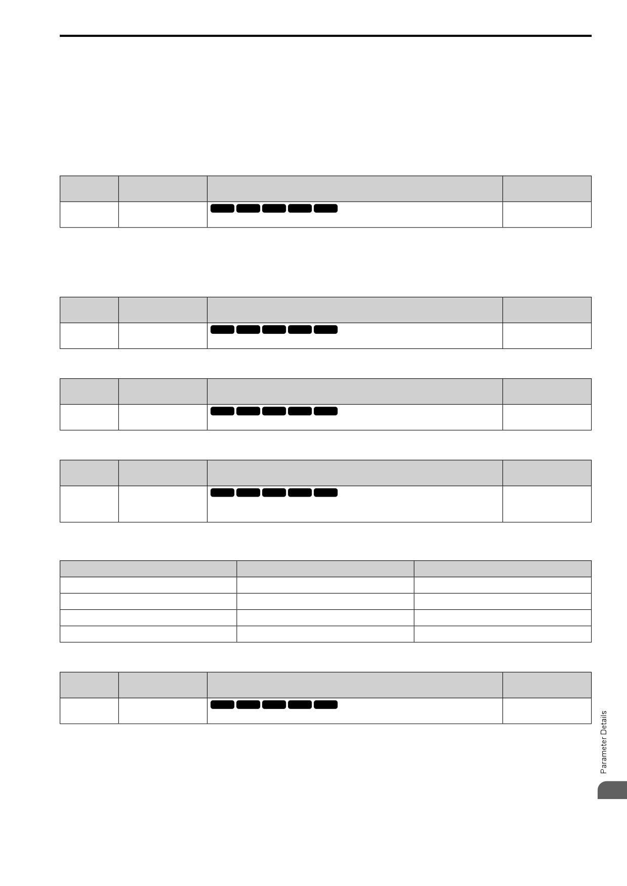
Table 12.16 shows how the soft-starter responds to PID input/output.
Table 12.16 Soft Starter and PID Input/Output
PID Frequency Reference
PID Frequency Reference
Selection
Soft Starter Input
Soft Starter Output
Input
Output
Soft Starter 1
Frequency Reference
Soft Starter Input
PID Frequency Reference Output
Output Frequency
Soft Starter 2
Soft Starter Output
Output Frequency
Frequency Reference
PID Frequency Reference Input
0 : Disab PID Softstart
478
12.2 b: APPLICATION
The soft starter process occurs downstream from the PID function. The PID function input functions as the
frequency reference, the PID function output functions as the soft starter input, and the soft starter output
functions as the output frequency.
1 : Enab PID Softstart
The soft starter process occurs upstream from the PID function. The soft starter input functions as the frequency
reference, the soft starter output functions as the PID function input, and the PID function output functions as the
output frequency.
■ b5-55: PID Fback Mon Selection
No.
Default
Name
Description
(Hex.)
(Range)
V/f
OLV OLV/PM AOLV/PM EZOLV
b5-55
PID Fback Mon Selection
000
(0BE1)
Sets the monitor (Ux-xx) used as the PID Feedback. Set the x-xx part of the Ux-xx [Monitor].
(000 - 999)
Note:
• You cannot select parameter U5-xx.
• This parameter is disabled when set to 000.
■ b5-56: PID FdbkMon Gain
No.
Default
Name
Description
(Hex.)
(Range)
b5-56
PID FdbkMon Gain
V/f
OLV OLV/PM AOLV/PM EZOLV
1.00
(0BE2)
Sets the gain for the monitor set in b5-55 [PID Fback Mon Selection].
(0.00
- 10.00)
■ b5-57: PID FdbkMon Bias
No.
Default
Name
Description
(Hex.)
(Range)
b5-57
PID FdbkMon Bias
V/f
OLV OLV/PM AOLV/PM EZOLV
0.00
(11DD)
Sets the bias for the monitor specified in b5-55 [PID Fback Mon Selection].
(-10.00 - +10.00)
■ b5-58 to b5-60: PID Setpoints 2 to 4
No.
Default
Name
Description
(Hex.)
(Range)
V/f
OLV OLV/PM AOLV/PM EZOLV
b5-58 to b5-60:
PID Setpoints 2 to 4
0.00%
(1182 - 1184)
Sets the PID setpoint when H1-xx = 77 or 78 [MFDI Function Selection = PID SP 1, PID SP 2].
(0.00
- 100.00%)
This value is a percentage of the maximum output frequency.
RUN
Table 12.17 shows how the different MFDI H1-xx values (77 and 78) have an effect on the PID setpoint value.
Table 12.17 Switching of MFDI and PID Setpoint Value
H1-xx = 77
H1-xx = 78
PID Setpoint Value
OFF
OFF
No switch
ON
OFF
b5-58 [PID Setpoint 2]
OFF
ON
b5-59 [PID Setpoint 3]
ON
ON
b5-60 [PID Setpoint 4]
■ b5-61: PID LoLim Select for Trim Mode
No.
Default
Name
Description
(Hex.)
(Range)
b5-61
PID LoLim Select for Trim
V/f
OLV OLV/PM AOLV/PM EZOLV
0
Mode
(119A)
Sets the function that adjusts the PID output in relation to the frequency reference.
(0, 1)
0 : Disabled
Does not adjust the PID output with the frequency reference.
1 : Enabled
Adjusts the PID output in relation to the frequency reference. The setting value of b5-62 [PID LoLim Value for
12
Trim Mode] sets the lower limit of the post-adjustment value. The maximum output frequency sets the upper limit.
479
12.2 b: APPLICATION
Note:
• Set b5-01 = 1 to enable this parameter.
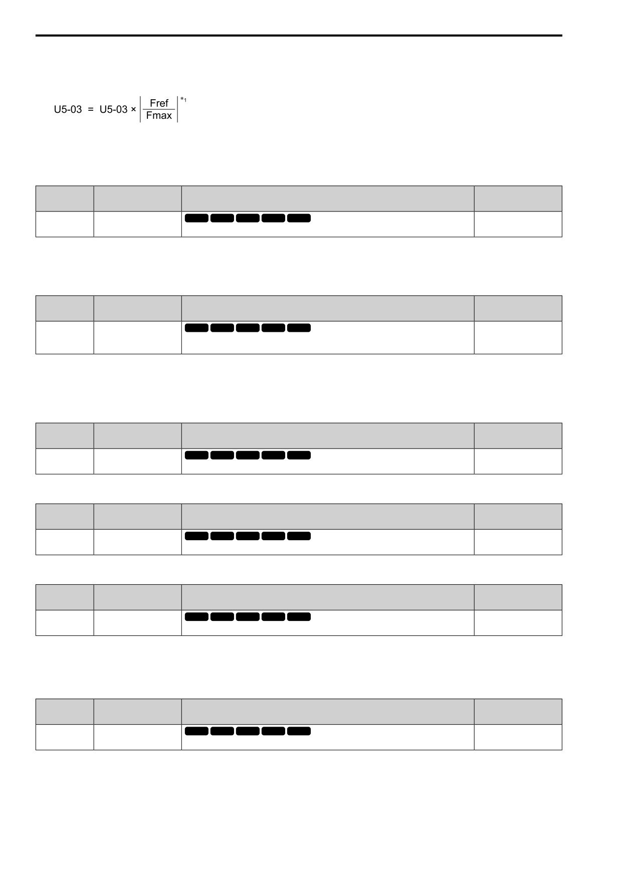
• When b5-61 = 1, you can use this formula to adjust PID output proportional to the frequency reference:
U5-03 [PID Output], Fref [Frequency Reference], and Fmax [Maximum Output Frequency]
*1
Lower limit = b5-62, Upper limit = Maximum output frequency
■ b5-62: PID LoLim Value for Trim Mode
No.
Default
Name
Description
(Hex.)
(Range)
b5-62
PID LoLim Value for Trim
V/f
OLV OLV/PM AOLV/PM EZOLV
0.00%
Mode
(119B)
Sets the PID Trim Mode Lower Limit Value as a percentage of the maximum output frequency.
(0.00
- 100.00%)
Note:
Set b5-01 = 1 to enable this parameter.
■ b5-63: PID DifFB Mon Selection
No.
Default
Name
Description
(Hex.)
(Range)
b5-63
PID DifFB Mon Selection
V/f
OLV OLV/PM AOLV/PM EZOLV
000
(119C)
Selects the monitor (Ux-xx) used as the PID Differential Feedback. Set the x-xx part of the Ux-xx
(000 - 999)
[Monitor].
Note:
• You cannot select parameter U5-xx.
• This parameter is disabled when set to 000.
■ b5-64: PID DifFB Mon Gain
No.
Default
Name
Description
(Hex.)
(Range)
b5-64
PID DifFB Mon Gain
V/f
OLV OLV/PM AOLV/PM EZOLV
1.00
(119D)
Sets the gain for the monitor specified in b5-63 [PID DifFB Mon Selection].
(0.00
- 10.00)
■ b5-65: PID DifFB Mon Bias
No.
Default
Name
Description
(Hex.)
(Range)
b5-65
PID DifFB Mon Bias
V/f
OLV OLV/PM AOLV/PM EZOLV
0.00
(119F)
Sets the bias for the monitor specified in b5-63 [PID DifFB Mon Selection].
(-10.00 - +10.00)
■ b5-66: PID Fback Mon Level
No.
Default
Name
Description
(Hex.)
(Range)
b5-66
PID Fback Mon Level
V/f
OLV OLV/PM AOLV/PM EZOLV
0
(11DE)
Sets the signal level for the monitor specified in b5-55 [PID Fback Mon Selection].
(0, 1)
0 : Absolute
1 : Bi-directional (+/-)
■ b5-67: PID DifFB Mon Level
No.
Default
Name
Description
(Hex.)
(Range)
b5-67
PID DifFB Mon Level
V/f
OLV OLV/PM AOLV/PM EZOLV
0
(11DF)
Sets the signal level for the monitor specified in b5-63 [PID DifFB Mon Selection].
(0, 1)
0 : Absolute
1 : Bi-directional (+/-)
480
12.2
b: APPLICATION
■ b5-89: Sleep Method Selection
No.
Default
Name
Description
(Hex.)
(Range)
b5-89
Sleep Method Selection
V/f
OLV OLV/PM AOLV/PM EZOLV
0
(0B89)
Sets sleep and wake up operation when using PID.
(0, 1)
RUN
0 : Standard
1 : EZ Sleep/Wake-up
■ b5-90: EZsleep Unit
No.
Default
Name
Description
(Hex.)
(Range)
V/f
OLV OLV/PM AOLV/PM EZOLV
b5-90
EZsleep Unit
0
(0B90)
Sets the measurement units for b5-91 [EZsleep Min Spd] and b5-92 [EZsleep Level].
(0, 1)
0 : rpm
1 : 0.1Hz units
■ b5-91: EZsleep Min Spd
No.
Default
Name
Description
(Hex.)
(Range)
b5-91
EZsleep Min Spd
V/f
OLV OLV/PM AOLV/PM EZOLV
0.0 Hz or 0 min-1 (r/min)
(0B91)
Sets the minimum speed for the EZ Sleep/Wakeup function. This parameter uses the largest value
(0.0 to 590.0 Hz or 0 to
from b5-91, b5-34 [PID Out Low Limit Level], and d2-02 [FRef Lower Limit].
35400 min-1 (r/min))
RUN
Note:
The value of b5-90 [b5-91: EZsleep Unit] sets the units. When b5-90 changes, this parameter does not automatically update. Set this
parameter again after you change b5-90 is changed.
■ b5-92: EZsleep Level
No.
Default
Name
Description
(Hex.)
(Range)
b5-92
EZsleep Level
V/f
OLV OLV/PM AOLV/PM EZOLV
0.0 Hz or 0 min-1 (r/min)
(0B92)
Sets the value that the output frequency or motor speed must be less than for longer than b5-93
(0.0 to 590.0 Hz or 0 to
[EZsleep Time] to enter Sleep Mode.
35400 min-1 (r/min))
RUN
Note:
When b5-90 [EZsleep Unit] changes, this parameter does not automatically update. Set this parameter again after you change b5-90.
■ b5-93: EZsleep Time
No.
Default
Name
Description
(Hex.)
(Range)
b5-93
EZsleep Time
V/f
OLV OLV/PM AOLV/PM EZOLV
5.0 s
(0B93)
Sets the length of time that the output frequency or motor speed must be less than b5-92 [EZsleep
(0.0 - 1000.0 s)
Level] to enter Sleep Mode.
RUN
■ b5-94: EZsleep Wake Level
No.
Default
Name
Description
(Hex.)
(Range)
b5-94
EZsleep Wake Level
V/f
OLV OLV/PM AOLV/PM EZOLV
0.00%
(0B94)
Sets the level at which the drive resumes operation when exiting Sleep Mode.
(0.00
- 600.00%)
RUN
Note:
The values of b5-20 [PID Unit Selection], b5-38 [PID SP User Scale for Display], and b5-39 [PID SP User digits for Display] set the
units. When b5-20, b5-38, and b5-39 change, this parameter does not automatically update. Set this parameter again after you change
b5-20, b5-38, and b5-39 are changed.
• When b5-95 = 1 [EZsleep Wake Mode = Absolute]:
12
When b5-09 = 0 [PID Output Level Selection = Normal output], and the PID Feedback [H3-xx = F] is less than
the value of b5-94 for a time longer than the value of b5-96 [EZsleep Wake Time], the drive will exit sleep and
481
12.2 b: APPLICATION
start operation again. When b5-09 = 1 [Reverse output], and the PID feedback is more than setting value of b5-
94 for a time longer than the setting value of b5-96, the drive will exit sleep and start operation again.
• When b5-95 = 0 [Setpoint Delta]:
When b5-09 = 0, and the PID feedback is less than the value of “PID setpoint value - b5-94” for a time longer
than the value of b5-96, the drive will exit sleep and start operation again. When b5-09 = 1, and the PID
feedback is more than the value of “PID setpoint value + b5-94” for a time longer than the setting value of b5-
96, the drive will exit sleep and start operation again.
■ b5-95: EZsleep Wake Mode
No.
Default
Name
Description
(Hex.)
(Range)
b5-95
EZsleep Wake Mode
V/f
OLV OLV/PM AOLV/PM EZOLV
0
(0B95)
Sets the wake-up mode to use when exiting Sleep Mode.
(0, 1)
0 : Setpoint Delta
1 : Absolute
■ b5-96: EZsleep Wake Time
No.
Default
Name
Description
(Hex.)
(Range)
V/f
OLV OLV/PM AOLV/PM EZOLV
b5-96
EZsleep Wake Time
1.0 s
(0B96)
Sets the EZ Wake-up time.
(0.0 - 1000.0 s)
RUN
When the PID feedback is less than the value of b5-94 [EZsleep Wake Level] continuously for the time set in b5-
96, the drive will exit sleep and start operation again.
◆ b6: DWELL FUNCTION
The Dwell function momentarily holds the output frequency at start and stop.
This prevents motor speed loss when you start and stop heavy loads. The Dwell function is also enabled when
backlash on the machine side causes sudden movement at the start of acceleration and deceleration.
At the start of acceleration, the drive uses the output frequency and acceleration time set for the Dwell function to
automatically operate at low speed to minimize the effects of backlash. Then, the drive can accelerate again. The
Dwell function operates the same for deceleration.
For conveyor applications, the Dwell function also lets the drive interlock the output frequency and a delay time
for the holding brake on the load side.
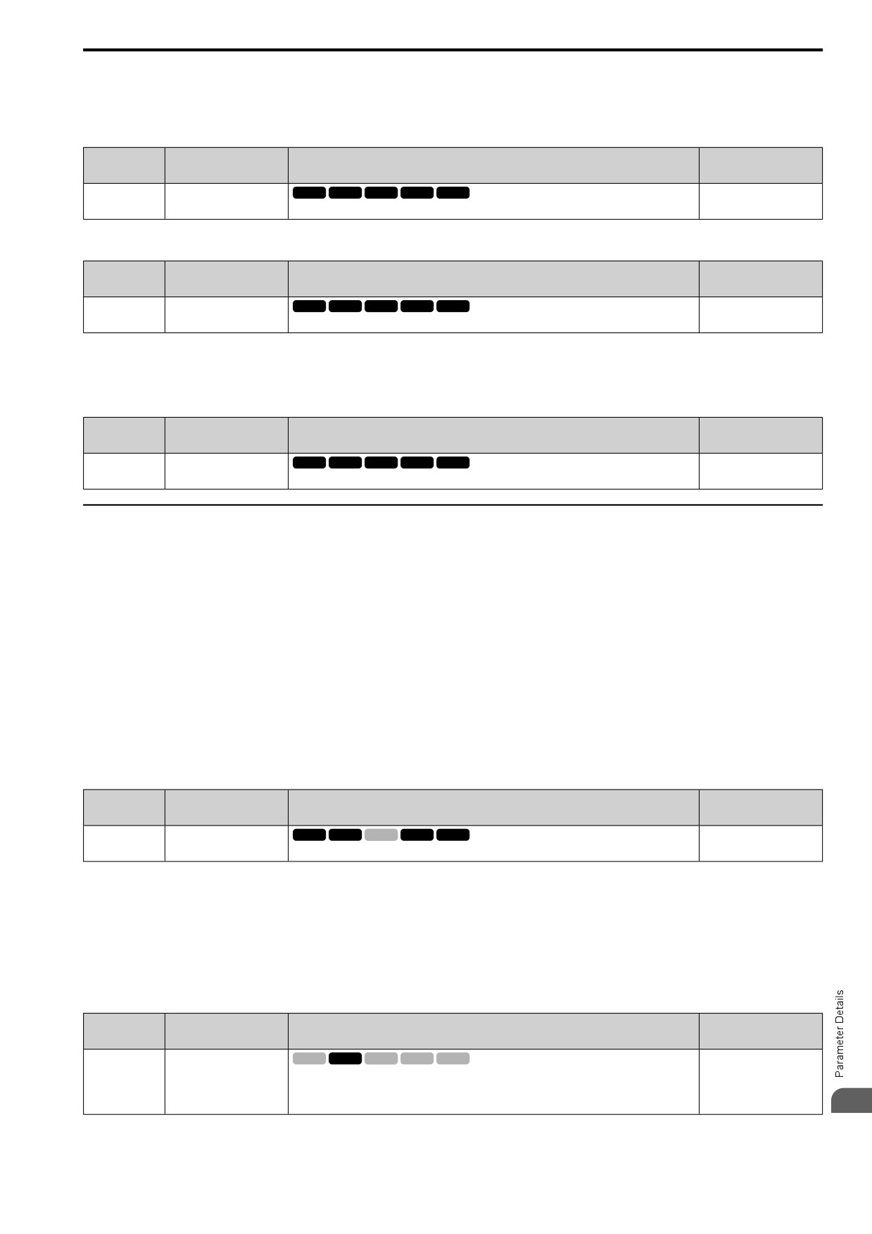
The Dwell function momentarily stops during acceleration to prevent a PM motor from stepping out. Figure 12.34
shows how the Dwell function works.
Note:
When you use the Dwell function at stop, set b1-03 = 0 [Stopping Method Selection = Ramp->Stop].
Figure 12.34 Time Chart for the Dwell Function at Start/Stop
■ b6-01: Dwell Ref.@Start
No.
Default
Name
Description
(Hex.)
(Range)
b6-01
Dwell Ref.@Start
V/f
OLV OLV/PM AOLV/PM EZOLV
0.0
(01B6)
Sets the output frequency that the drive will hold momentarily when the motor starts.
(Determined by A1-02)
482
12.2 b: APPLICATION
When the drive accelerates to the output frequency set in b6-01, it holds that frequency for the time set in b6-02
[Dwell Time@Start], and starts to accelerate again.
■ b6-02: Dwell Time@Start
No.
Default
Name
Description
(Hex.)
(Range)
b6-02
Dwell Time@Start
V/f
OLV OLV/PM AOLV/PM EZOLV
0.0 s
(01B7)
Sets the length of time that the drive will hold the output frequency when the motor starts.
(0.0 - 10.0 s)
■ b6-03: Dwell Ref@Stop
No.
Default
Name
Description
(Hex.)
(Range)
V/f
OLV OLV/PM AOLV/PM EZOLV
b6-03
Dwell Ref@Stop
0.0
(01B8)
Sets the output frequency that the drive will hold momentarily when ramping to stop the motor.
(Determined by A1-02)
When the drive decelerates to the output frequency set in b6-03, it holds that frequency for the time set in b6-04
[Dwell Time@Stop] and starts to decelerate again.
■ b6-04: Dwell Time@Stop
No.
Default
Name
Description
(Hex.)
(Range)
b6-04
Dwell Time@Stop
V/f
OLV OLV/PM AOLV/PM EZOLV
0.0 s
(01B9)
Sets the length of time for the drive to hold the output frequency when ramping to stop the motor.
(0.0 - 10.0 s)
◆ b8: ENERGY SAVING
Energy-saving control improves overall system operating efficiency by operating the motor at its most efficient
level.
Set b8-01 and these parameters according to the control method and the motor.
• When you use V/f Control, set parameters b8-04 to b8-06.
• When you use vector control with an induction motor, set parameters b8-02 and b8-03.
• When you use a PM motor, set parameters b8-16 and b8-17.
Note:
• Energy-saving control is not appropriate for applications with sudden changes in the load, or applications driving heavy loads such as a
traverse car application.
• Energy-saving control maximizes operation based on precise motor data set to the drive. Make sure that you do Auto-Tuning and enter
the correct information about the motor before you use the Energy-saving control.
■ b8-01: eSave Ctrl Selection
No.
Default
Name
Description
(Hex.)
(Range)
b8-01
eSave Ctrl Selection
V/f
OLV OLV/PM AOLV/PM EZOLV
0
(01CC)
Sets the Energy-saving control function.
(0 - 2)
0 : Disabled
1 : Enabled
2 : Search Enabled
Note:
When A1-02 = 6 [Control Method = PM AOLVector], you can only select setting 2 in Expert Mode.
■ b8-02: eSave Ctrl Gain
No.
Default
Name
Description
(Hex.)
(Range)
b8-02
eSave Ctrl Gain
V/f
OLV OLV/PM AOLV/PM EZOLV
Determined by A1-02
(01CD)
Sets the gain for Energy-saving control.
(0.0
- 10.0)
RUN
Expert
12
Increase the setting value to increase energy saving. If the setting value is too large, the motor will stall.
483
12.2 b: APPLICATION
■ b8-03: eSave Filter Time
No.
Default
Name
Description
(Hex.)
(Range)
b8-03
eSave Filter Time
V/f
OLV OLV/PM AOLV/PM EZOLV
Determined by A1-02, C6-
01 and o2-04
(01CE)
Sets the responsiveness for Energy-saving control.
(0.00 - 10.00 s)
RUN
Expert
Decrease the setting value to increase responsiveness. If the setting value is too low, operation will not be stable.
■ b8-04: eSave Coef. Value
No.
Default
Name
Description
(Hex.)
(Range)
b8-04
eSave Coef. Value
V/f
OLV OLV/PM AOLV/PM EZOLV
Determined by C6-01, E2-
11, and o2-04
(01CF)
Sets the Energy-saving control coefficient to maintain maximum motor efficiency. The default
setting is for Yaskawa motors.
(0.00
- 655.00)
Expert
When you use a motor from a different manufacturer, increase the setting value in 5% increments to find the
minimum value for U1-08 [Output Power] at light loads.
When you decrease the setting value, it decreases the output voltage and decreases power consumption. If the
setting value is too low, the motor will stall.
Note:
When you do Rotational Auto-Tuning, the drive will automatically set the energy-saving coefficient.
■ b8-05: Power Det.Filter Time
No.
Default
Name
Description
(Hex.)
(Range)
b8-05
Power Det.Filter Time
V/f
OLV OLV/PM AOLV/PM EZOLV
20 ms
(01D0)
Sets the time constant to measure output power.
(0 - 2000 ms)
Expert
Decrease the setting value to increase responsiveness to load changes. If you set the value too low during
operation at light loads, motor speed is not stable.
■ b8-06: Srch Op.Volt Limit
No.
Default
Name
Description
(Hex.)
(Range)
V/f
OLV OLV/PM AOLV/PM EZOLV
b8-06
Srch Op.Volt Limit
0%
(01D1)
Sets the voltage limit for Search Operation as a percentage of the motor rated voltage.
(0 - 100%)
Expert
The Search Operation changes the output voltage in small increments to find a setpoint at which the drive can use
minimum power to operate.
Set this parameter to 0 to disable Search Operation. This will not disable Energy-saving control.
If the setting value is too low, the motor will stall when loads suddenly increase.
■ b8-16: PM eSave Coef.Ki
No.
Default
Name
Description
(Hex.)
(Range)
b8-16
PM eSave Coef.Ki
V/f
OLV OLV/PM AOLV/PM EZOLV
1.00
(01F8)
Sets torque linearity. This parameter uses the Ki value from the motor nameplate. Usually it is not
(0.00
- 3.00)
necessary to change this setting.
Expert
When b8-16 = 1.00 (default), the drive will automatically calculate and control the energy-saving coefficient. If
the motor nameplate has a description for “Ki”, set this parameter to the Ki value.
Do this procedure to prevent oscillation when you set b8-01 = 1 [eSave Ctrl Selection = Enabled].
1. Check U5-21 [Energy Save Ki Coeff] and make sure that it aligns with the Ki value on the motor nameplate.
2. If the numbers are different, set b8-16 to the Ki value on the motor nameplate.
484
12.2 b: APPLICATION
■ b8-17: PM eSave Coef.Kt
No.
Default
Name
Description
(Hex.)
(Range)
b8-17
PM eSave Coef.Kt
V/f
OLV OLV/PM AOLV/PM EZOLV
1.00
(01F9)
Sets torque linearity. This parameter uses the Kt value from the motor nameplate. Usually it is not
(0.00
- 3.00)
necessary to change this setting.
Expert
When E5-01 = 1xxx [PM Mot Code Selection = Yaskawa SSR1 series IPM motor], the drive automatically
calculates the energy-saving coefficient Kt and uses that value to control operation.
Do this procedure to prevent oscillation when you set b8-01 = 1 [eSave Ctrl Selection = Enabled].
1. Check U5-22 [Energy Save Kt Coeff] and make sure that it aligns with the Kt value on the motor nameplate.
2. If the numbers are different, set b8-17 to the Kt value on the motor nameplate.
■ b8-18: eSave d-Axis Filter Time
No.
Default
Name
Description
(Hex.)
(Range)
V/f
OLV OLV/PM AOLV/PM EZOLV
b8-18
eSave d-Axis Filter Time
0.100 s
(01FA)
Sets the d-axis current reference filter time constant.
(0.000 - 5.000 s)
Expert
■ b8-19: eSave Search Frequency
No.
Default
Name
Description
(Hex.)
(Range)
b8-19
eSave Search Frequency
V/f
OLV OLV/PM AOLV/PM EZOLV
Determined by A1-02
(0B40)
Sets the frequency of Energy-saving control search operations. Usually it is not necessary to
(10 - 300 Hz)
change this setting.
Expert
Note:
• If low inertia causes vibration in the machine, increase the setting value in 10 Hz increments and check the response. If A1-02 = 8
[Control Method = EZ Vector], increase the setting value in 1 Hz increments.
• To make the motor more efficient, decrease the setting value in 1 Hz increments until the point immediately before machine vibration
starts to occur.
■ b8-20: PM eSave Width for Test
No.
Default
Name
Description
(Hex.)
(Range)
b8-20
PM eSave Width for Test
V/f
OLV OLV/PM AOLV/PM EZOLV
1.0 degrees
(0B41)
Sets the amplitude of Energy-saving control search operations.
(0.1 - 5.0 degrees)
Expert
An increase in the value can make the operational efficiency better. However, if the load inertia is small, it may be
necessary to adjust the value to prevent machine vibration.
Note:
• If low inertia causes vibration in the machine, decrease the setting value in 1.0-degree increments and check the response.
• To make the motor more efficient, increase the setting value in 1.0-degreee increments until the point immediately before machine
vibration starts to occur.
■ b8-21: PM eSave Gain for Test
No.
Default
Name
Description
(Hex.)
(Range)
b8-21
PM eSave Gain for Test
V/f
OLV OLV/PM AOLV/PM EZOLV
0.3Hz
(0B42)
Sets the gain of Energy-saving control search operations.
(0.1 - 20.0 Hz)
Expert
When you decrease the value of C5-01 [ASR PGain 1], also decrease the value of b8-21 to keep the correct ratio.
12
485
12.2 b: APPLICATION
■ b8-22: PM eSave LPF Cutoff Frq
No.
Default
Name
Description
(Hex.)
(Range)
b8-22
PM eSave LPF Cutoff Frq
V/f
OLV OLV/PM AOLV/PM EZOLV
10.0 Hz
(0B43)
Sets the frequency of the filter used to extract the high-efficiency phase from search operations.
(1.0 - 30.0 Hz)
Usually it is not necessary to change this setting.
Expert
■ b8-23: PM eSave Srch Limit
No.
Default
Name
Description
(Hex.)
(Range)
b8-23
PM eSave Srch Limit
V/f
OLV OLV/PM AOLV/PM EZOLV
15.0 degrees
(0B44)
Sets the search operations output limit. Usually it is not necessary to change this setting.
(0.0 - 30.0 degrees)
Expert
When the motor characteristics are correct, increase this value to make the motor more efficient.
■ b8-24: PM eSave HiF Gain for ACR
No.
Default
Name
Description
(Hex.)
(Range)
b8-24
PM eSave HiF Gain for
V/f
OLV OLV/PM AOLV/PM EZOLV
200.0 Hz
ACR
(0B45)
Sets the gain for high-frequency current control.
(100.0 - 1000.0 Hz)
Expert
Note:
If the drive detects oC [Overcurrent], decrease the value.
■ b8-25: PM eSave Srch Start Level
No.
Default
Name
Description
(Hex.)
(Range)
b8-25
PM eSave Srch Start Level
V/f
OLV OLV/PM AOLV/PM EZOLV
10.0%
(0B46)
Sets the start level for search operations.
(0.0
- 100.0%)
Expert
Note:
If there is vibration in the machine, increase the value.
■ b8-26: PM eSave Pwr SP Setpoint
No.
Default
Name
Description
(Hex.)
(Range)
b8-26
PM eSave Pwr SP Setpoint
V/f
OLV OLV/PM AOLV/PM EZOLV
0.0%
(0B47)
Sets a value to increase torque accuracy.
(-10.0 - +10.0%)
Expert
■ b8-28: OverExc Action Selection
No.
Default
Name
Description
(Hex.)
(Range)
V/f
OLV OLV/PM AOLV/PM EZOLV
b8-28
OverExc Action Selection
0
(0B8B)
Sets the function for excitation operation.
(0, 1)
Expert
When operation is not stable at low speeds, set this parameter to 1 to enable the function.
0 : Disabled
1 : Enabled
■ b8-29: eSave Priority Mode
No.
Default
Name
Description
(Hex.)
(Range)
b8-29
eSave Priority Mode
V/f
OLV OLV/PM AOLV/PM EZOLV
0
(0B8C)
Sets the priority of drive response between changes to the load or Energy-saving control. Enable
(0, 1)
this to prioritize energy-saving control. Disable this to prioritize tracking related to fast load
changes, and prevent motor stall.
486
12.2 b: APPLICATION
Enable this parameter when there are small changes in the load. It is possible that the motor cannot respond
correctly to changes in the load.
0 : Priority: Drive Response
1 : Priority: Energy Savings
12
487
12.3 C: TUNING
12.3
C: TUNING
C parameters adjust drive operation, including:
• Acceleration Time
• Deceleration Time
• Slip Compensation
• Torque Compensation
• Carrier Frequency
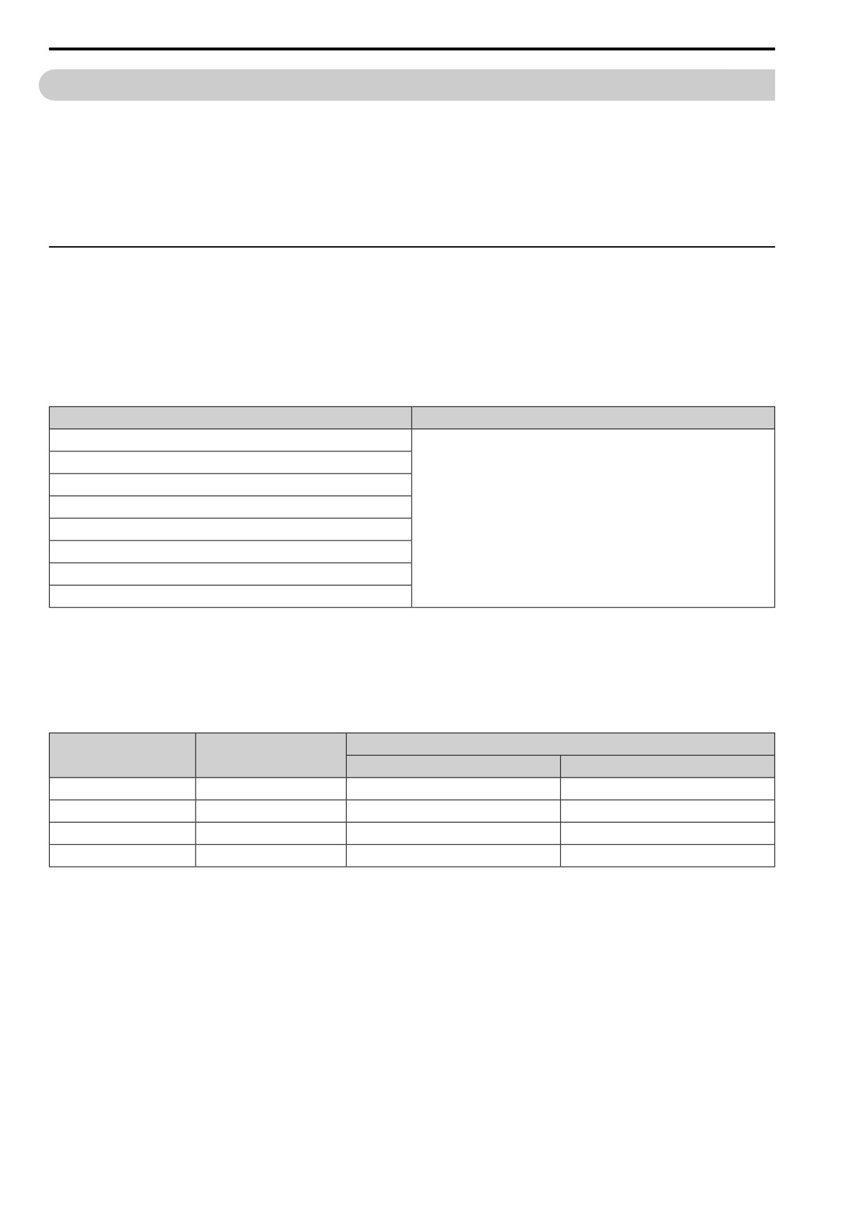
◆ C1: ACCEL / DECEL
You can set four different acceleration and deceleration time pairs in the drive. When you activate and deactivate
H1-xx = 18, 19, 61 [MFDI Function Select = Ac/Dec Time1, Ac/Dec Time2, Motor 2 Select], you can switch
acceleration and deceleration times during run.
Acceleration time parameters always set the time to accelerate from 0 Hz to E1-04 [Max Output Frequency].
Deceleration time parameters always set the time to decelerate from E1-04 to 0 Hz.
C1-01 [Accel Time 1] and C1-02 [Decel Time 1] are the default active accel/decel settings.
Parameter
Range
C1-01 [Accel Time 1]
C1-02 [Decel Time 1]
C1-03 [Accel Time 2]
C1-04 [Decel Time 2]
0.0 to 6000.0 s
C1-05 [Accel Time 3]
C1-06 [Decel Time 3]
C1-07 [Accel Time 4]
C1-08 [Decel Time 4]
Note:
The setting range for acceleration and deceleration times is 0.00 to 600.00 s when C1-10 = 0 [Ac/Dec Units = 0.01s].
■ Use MFDIs to Switch Acceleration Times
Table 12.18 shows the different acceleration and deceleration times.
Table 12.18 Accel/Decel Times and Active Parameters
Active Parameter
H1-xx = 18
H1-xx = 19
[Ac/Dec Time1]
[Ac/Dec Time2]
Acceleration Time
Deceleration Time
OFF
OFF
C1-01 [Accel Time 1]
C1-02 [Decel Time 1]
ON
OFF
C1-03 [Accel Time 2]
C1-04 [Decel Time 2]
OFF
ON
C1-05 [Accel Time 3]
C1-06 [Decel Time 3]
ON
ON
C1-07 [Accel Time 4]
C1-08 [Decel Time 4]
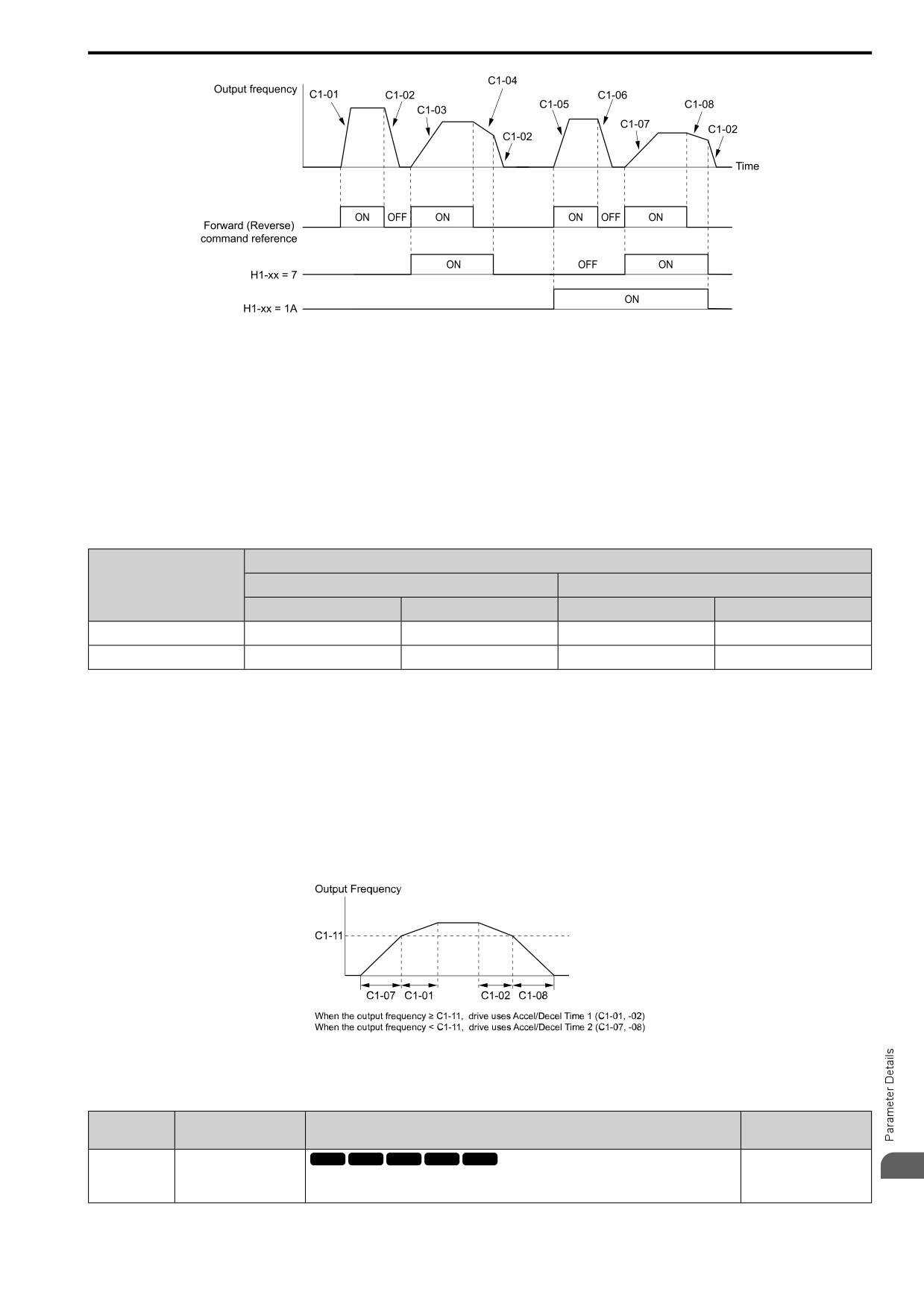
Figure 12.35 shows an operation example to change acceleration and deceleration times. It is necessary to set b1-
03 = 0 [Stopping Method Selection = Ramp->Stop] for this example.
488
12.3 C: TUNING
Figure 12.35 Timing Diagram of Acceleration and Deceleration Times
■ Use Motor Selection to Switch Acceleration and Deceleration Times
When you set H1-xx = 61 [MFDI Function Select = Motor 2 Select], you can activate and deactivate the input
terminal to switch between motor 1 and motor 2.
Note:
You cannot use the Motor 2 Selection function with PM motors.
Table 12.19 shows the possible acceleration and deceleration time combinations when you use the Motor 2
Selection function.
Table 12.19 Motor Selection and Acceleration and Deceleration Times
H1-xx = 61 [Motor 2 Select]
H1-xx = 18
Motor 2 Selection: OFF
Motor 2 Selection: ON
[Ac/Dec Time1]
Acceleration Time
Deceleration Time
Acceleration Time
Deceleration Time
OFF
C1-01
C1-02
C1-05
C1-06
ON
C1-03
C1-04
C1-07
C1-08
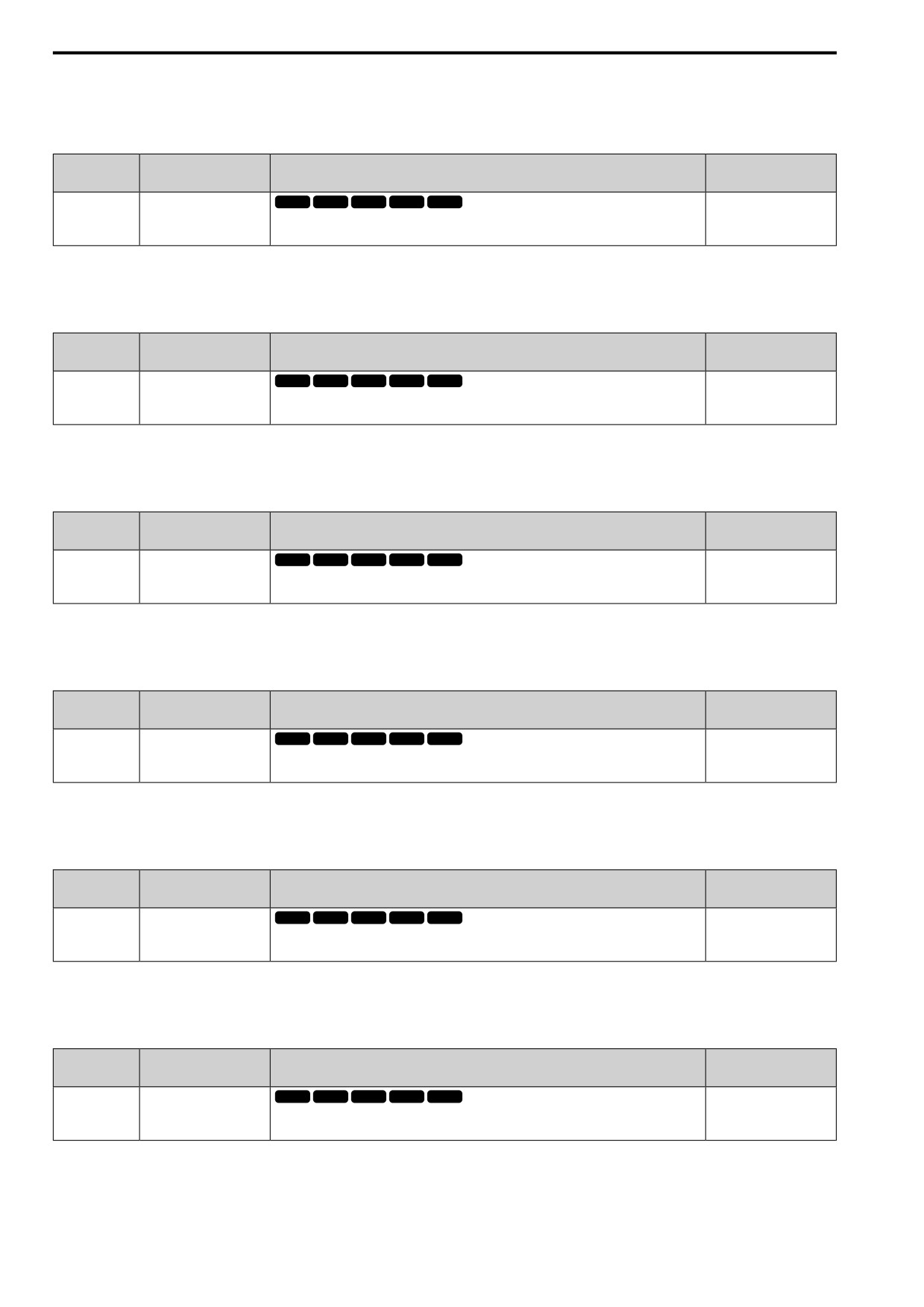
■ Use Output Frequency Level to Switch Acceleration and Deceleration Times
The drive can use output frequency to automatically switch between different acceleration and deceleration times.
When the output frequency = C1-11 [Accel/Decel Time Switchover Freq], the drive automatically switches the
acceleration and deceleration times. Set C1-11 = 0.0 Hz to disable this function.
Note:
• Acceleration and deceleration times set to MFDIs are more important than the automatic switch using the frequency level set in C1-11.
For example, if you set the switchover frequency to C1-11, the drive will not automatically switch acceleration and deceleration times
when the MFDI terminal set for Ac/Dec Time1 [H1-xx = 18] is activated.
• If Motor 2 Select [H1-xx = 61] is activated, the drive will set the acceleration/deceleration time to C1-05 and C1-06 for motor 2 when
the output frequency is more than the frequency level set in C1-11.
Figure 12.36 Accel/Decel Time Switching Frequency
■ C1-01: Accel Time 1
No.
Default
Name
Description
(Hex.)
(Range)
C1-01
Accel Time 1
V/f
OLV OLV/PM AOLV/PM EZOLV
10.0 s
12
(0200)
Sets the length of time to accelerate from zero to maximum output frequency.
(0.0 - 6000.0 s)
RUN
489
12.3 C: TUNING
Note:
When C1-10 = 0 [Ac/Dec Units =
0.01s], the setting range is 0.00 to 600.00 s.
■ C1-02: Decel Time 1
No.
Default
Name
Description
(Hex.)
(Range)
C1-02
Decel Time 1
V/f
OLV OLV/PM AOLV/PM EZOLV
10.0 s
(0201)
Sets the length of time to decelerate from maximum output frequency to zero.
(0.0 - 6000.0 s)
RUN
Note:
When C1-10 = 0 [Ac/Dec Units =
0.01s], the setting range is 0.00 to 600.00 s.
■ C1-03: Accel Time 2
No.
Default
Name
Description
(Hex.)
(Range)
C1-03
Accel Time 2
V/f
OLV OLV/PM AOLV/PM EZOLV
10.0 s
(0202)
Sets the length of time to accelerate from zero to maximum output frequency.
(0.0 - 6000.0 s)
RUN
Note:
When C1-10 = 0 [Ac/Dec Units =
0.01s], the setting range is 0.00 to 600.00 s.
■ C1-04: Decel Time 2
No.
Default
Name
Description
(Hex.)
(Range)
C1-04
Decel Time 2
V/f
OLV OLV/PM AOLV/PM EZOLV
10.0 s
(0203)
Sets the length of time to decelerate from maximum output frequency to zero.
(0.0 - 6000.0 s)
RUN
Note:
When C1-10 = 0 [Ac/Dec Units =
0.01s], the setting range is 0.00 to 600.00 s.
■ C1-05: Accel Time 3
No.
Default
Name
Description
(Hex.)
(Range)
C1-05
Accel Time 3
V/f
OLV OLV/PM AOLV/PM EZOLV
10.0 s
(0204)
Sets the length of time to accelerate from zero to maximum output frequency.
(0.0 - 6000.0 s)
RUN
Note:
When C1-10 = 0 [Ac/Dec Units =
0.01s], the setting range is 0.00 to 600.00 s.
■ C1-06: Decel Time 3
No.
Default
Name
Description
(Hex.)
(Range)
V/f
OLV OLV/PM AOLV/PM EZOLV
C1-06
Decel Time 3
10.0 s
(0205)
Sets the length of time to decelerate from maximum output frequency to zero.
(0.0 - 6000.0 s)
RUN
Note:
When C1-10 = 0 [Ac/Dec Units =
0.01s], the setting range is 0.00 to 600.00 s.
■ C1-07: Accel Time 4
No.
Default
Name
Description
(Hex.)
(Range)
C1-07
Accel Time 4
V/f
OLV OLV/PM AOLV/PM EZOLV
10.0 s
(0206)
Sets the length of time to accelerate from zero to maximum output frequency.
(0.0 - 6000.0 s)
RUN
Note:
When C1-10 = 0 [Ac/Dec Units =
0.01s], the setting range is 0.00 to 600.00 s.
490
12.3 C: TUNING
■ C1-08: Decel Time 4
No.
Default
Name
Description
(Hex.)
(Range)
C1-08
Decel Time 4
V/f
OLV OLV/PM AOLV/PM EZOLV
10.0 s
(0207)
Sets the length of time to decelerate from maximum output frequency to zero.
(0.0 - 6000.0 s)
RUN
Note:
When C1-10 = 0 [Ac/Dec Units = 0.01s], the setting range is 0.00 to 600.00 s.
■ C1-09: Fast Stop Time
No.
Default
Name
Description
(Hex.)
(Range)
C1-09
Fast Stop Time
V/f
OLV OLV/PM AOLV/PM EZOLV
10.0 s
(0208)
Sets the length of time that the drive will decelerate to zero for a Fast Stop.
(0.0 - 6000.0 s)
RUN
Note:
• When C1-10 = 0 [Ac/Dec Units = 0.01s], the setting range is 0.00 to 600.00 s.
• When L2-29 = 1 [KEB Method = Single KEB1 Ride-Thru] and you do KEB Auto-Tuning, the drive will automatically set C1-09. If
you must not change the Fast Stop time, do not do KEB Auto-Tuning.
The Fast Stop function will be triggered in the following circumstances.
• The Fast Stop operation will be triggered by the input of the Fast Stop command via the multi-function digital
input terminal.
• The Fast Stop operation is will be triggered when by the input of the Fast Stop command is input via the multi-
function digital input terminal.
Set H1-xx = 34, 35 [MFDI Function Select = Fast Stop NO, Fast Stop NC].
When the Fast Stop command is input, the Fast Stop operation will be triggered at the deceleration time set to C1-
09. The drive cannot be restarted after initiating a Fast Stop operation until deceleration is complete. Complete
deceleration and cycle the Run command to clear the Fast Stop input.
The terminal set for H2-xx = 17 [MFDO Function Select = @Fast Stop] will be ON during Fast Stop.
Note:
Decelerating too quickly can cause an ov [Overvoltage] fault that shuts off the drive while the motor to coasts to a stop. Set a Fast Stop
time in C1-09 that prevents motor coasting and makes sure that the motor stops quickly and safely.
■ C1-10: Ac/Dec Units
No.
Default
Name
Description
(Hex.)
(Range)
C1-10
Ac/Dec Units
V/f
OLV OLV/PM AOLV/PM EZOLV
1
(0209)
Sets the setting units for C1-01 to C1-08 [Accel Time 1 to Decel Time 4], C1-09 [Fast Stop Time],
(0, 1)
L2-06 [KEB Decel Time], and L2-07 [KEB Accel Time].
0 : 0.01s
Sets acceleration and deceleration times in 0.01 s units. The setting range is 0.0 to 6000.0 s.
If one of these parameters is set to 1000.0 s or longer, you cannot set C1-10 = 0:
• C1-01 to C1-09
• L2-06
• L2-07
When one of those parameters is set to a value between 600.1 s and 1000.0 s, you can set C1-10 = 0, but the time
will change to 600.00 s.
1 : 0.1s
Sets acceleration and deceleration times in 0.1 s units. The setting range is 0.0 to 6000.0 s.
■ C1-11: Ac/Dec Switch Frequency
No.
Default
Name
Description
(Hex.)
(Range)
12
V/f
OLV OLV/PM AOLV/PM EZOLV
C1-11
Ac/Dec Switch Frequency
Determined by A1-02
(020A)
Sets the frequency at which the drive will automatically change acceleration and deceleration
(0.0 - 590.0 Hz)
times.
491
12.3 C: TUNING
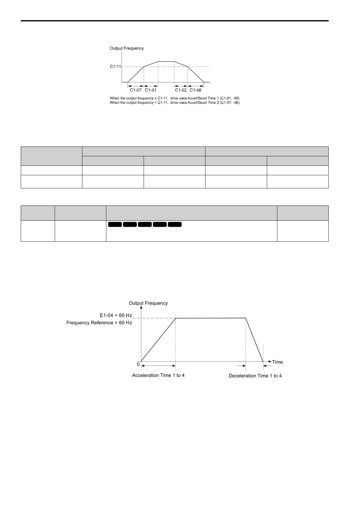
When output frequency get C1-11 value, the drive automatically switches the acceleration and deceleration times.
Set this parameter to 0.0 to disable this function.
Figure 12.37 Accel/Decel Time Switching Frequency
Table 12.20 lists the possible combinations of acceleration and deceleration time switchover frequencies and the
acceleration times for the Motor 2 Selection function.
Table 12.20 Motor and Acceleration and Deceleration Time Combination
Motor 1
Motor 2
C1-11
Acceleration Time
Deceleration Time
Acceleration Time
Deceleration Time
Less than the setting value
C1-07 [Accel Time 4]
C1-08 [Decel Time 4]
C1-07 [Accel Time 4]
C1-08 [Decel Time 4]
Equal to or more than the setting
C1-01 [Accel Time 1]
C1-02 [Decel Time 1]
C1-05 [Accel Time 3]
C1-06 [Decel Time 3]
value
■ C1-14: Ac/Dec Base Frequency
No.
Default
Name
Description
(Hex.)
(Range)
C1-14
Ac/Dec Base Frequency
V/f
OLV OLV/PM AOLV/PM EZOLV
0.0 Hz
(0264)
Sets the base frequency used to calculate acceleration and deceleration rates.
(0.0 - 590.0 Hz)
RUN
The acceleration and deceleration rates set in C1-01 to C1-09 [Accel Time 1 to Decel Time 4, Fast Stop Time] will
change when the value of C1-14 changes.
• When C1-14 = 0.0 Hz
- C1-01, C1-03, C1-05, C1-07 [Accel Time 1 to Accel Time 4]: Time to accelerate from 0 Hz to E1-04 [Max
Output Frequency]
- C1-02, C1-04, C1-06, C1-08 [Decel Time 1 to Decel Time 4]: Time to decelerate from E1-04 to 0 Hz.
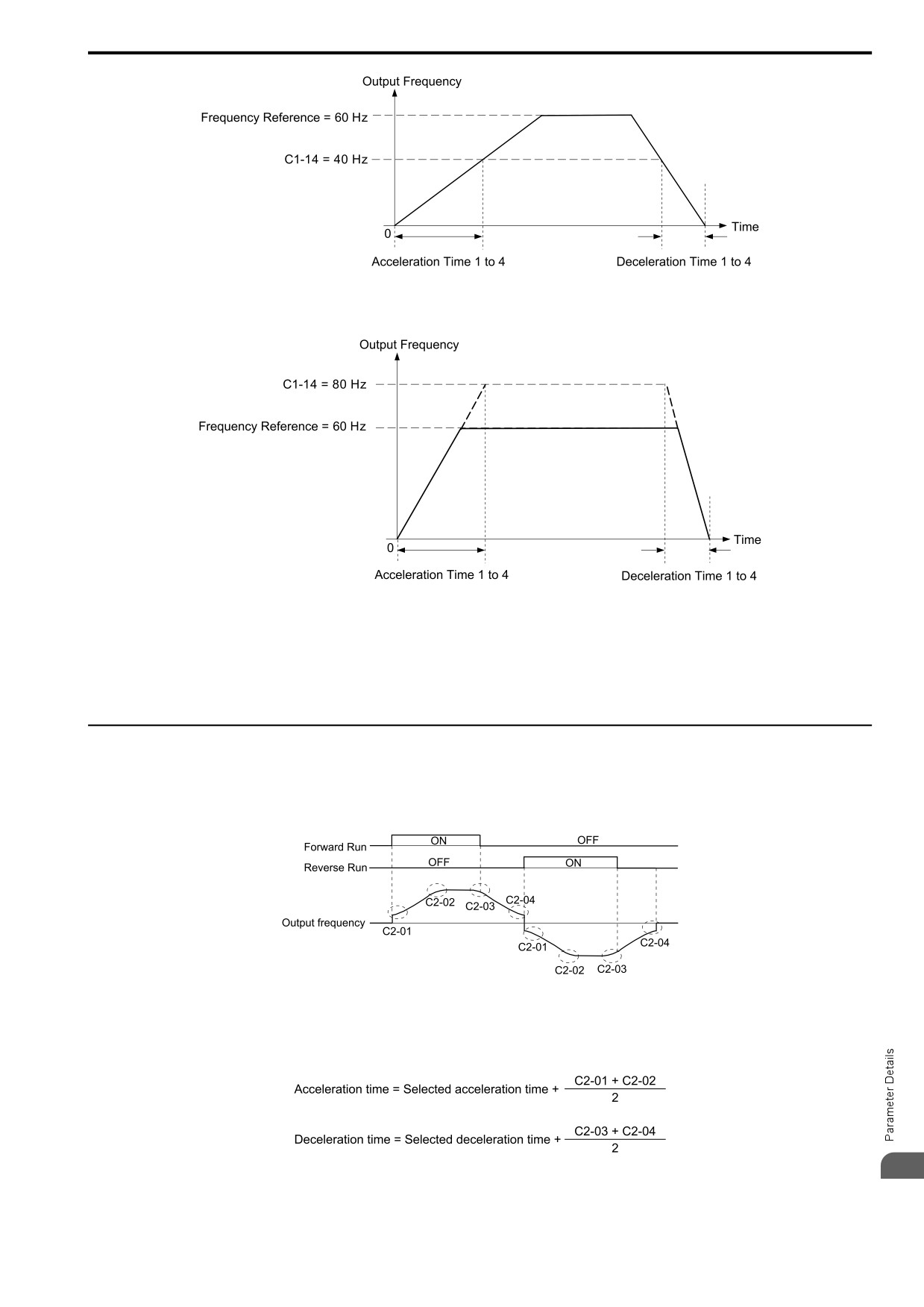
Figure 12.38 Example 1: Acceleration/Deceleration Rate (When C1-14 = 0 Hz, E1-04 = 60 Hz, and the Frequency
Reference is 60 Hz)
• When C1-14 ≠ 0.0 Hz
- C1-01, C1-03, C1-05, C1-07: Time to accelerate from 0 Hz to C1-14
– C1-02, C1-04, C1-06, C1-08, C1-09: Time to decelerate from C1-14 to 0 Hz
492
12.3 C: TUNING
Figure 12.39 Example 2: Acceleration/Deceleration Rate (When C1-14 = 40 Hz, E1-04 = 60 Hz, and the Frequency
Reference is 60 Hz)
Figure 12.40 Example 3: Acceleration/Deceleration Rate (When C1-14 = 80 Hz, E1-04 = 60 Hz, and the Frequency
Reference is 60 Hz)
Note:
• Figure 12.38 to Figure 12.40 show the accel/decel times when C2-01 to C2-04 [Jerk@Start of Accel to Jerk@End of Decel] = 0.00 s.
• When L3-01 ≠ 1 [StallP Mode@Accel≠ Disabled], Stall Prevention could cause the acceleration time to be longer than the set value.
• When L3-04 ≠ 0 [StallP@Decel Enable ≠ Disabled], Stall Prevention could cause the deceleration time to be longer than the set value.
◆ C2: JERK CONTROL
Use S-curve characteristics to smooth acceleration and deceleration and to minimize abrupt shock to the load.
Set S-curve characteristic time during acceleration/deceleration at start and acceleration/deceleration at stop.
The following figure explains how S-curves are applied.
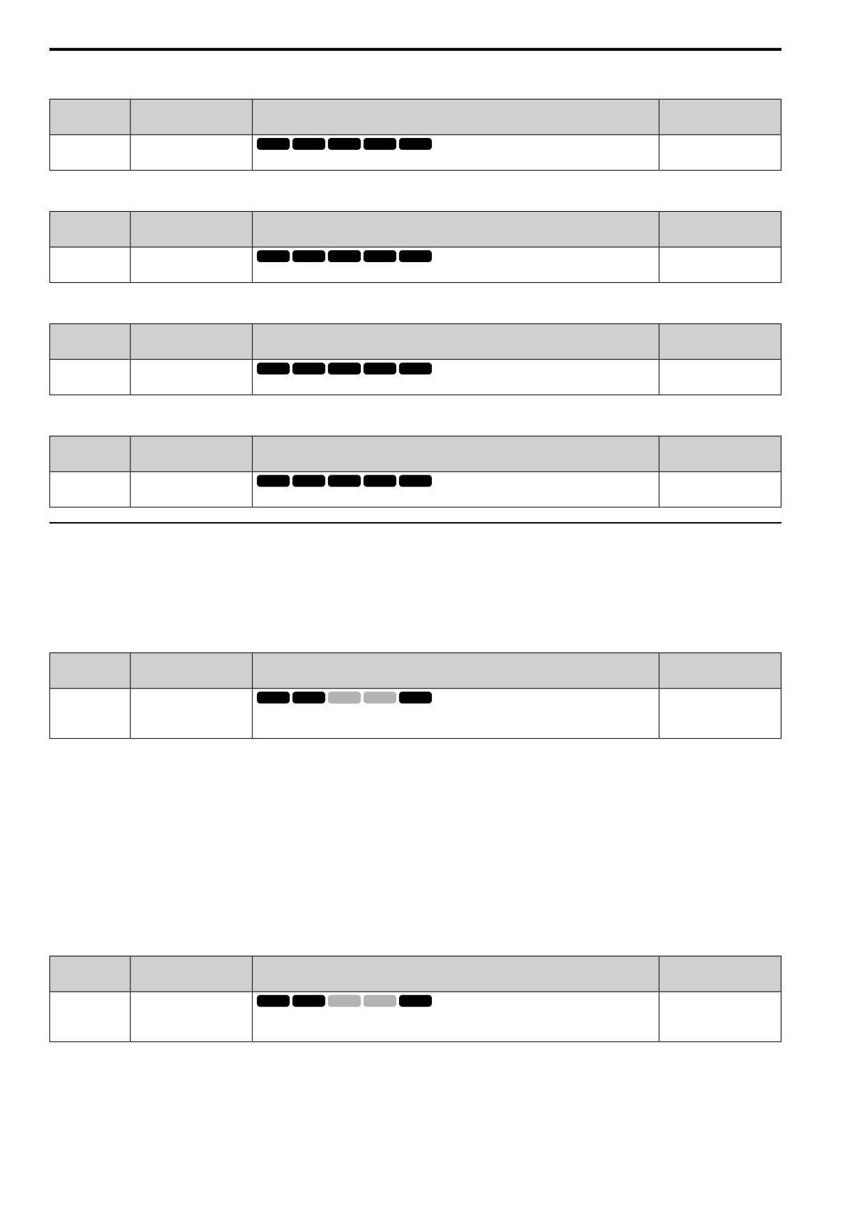
Figure 12.41 S-Curve Timing Diagram - Forward/Reverse Operation
Note:
• If STPo [Motor Step-Out Detected] occurs when starting a PM motor, try increasing the value set to C2-01.
• Setting the S-curve will increase the acceleration and deceleration times.
12
493
12.3 C: TUNING
■ C2-01: Jerk@Start of Accel
No.
Default
Name
Description
(Hex.)
(Range)
C2-01
Jerk@Start of Accel
V/f
OLV OLV/PM AOLV/PM EZOLV
Determined by A1-02
(020B)
Sets the S-curve acceleration time at start.
(0.00 - 10.00 s)
■ C2-02: Jerk@End of Accel
No.
Default
Name
Description
(Hex.)
(Range)
C2-02
Jerk@End of Accel
V/f
OLV OLV/PM AOLV/PM EZOLV
0.20 s
(020C)
Sets the S-curve acceleration time at completion.
(0.00 - 10.00 s)
■ C2-03: Jerk@Start of Decel
No.
Default
Name
Description
(Hex.)
(Range)
C2-03
Jerk@Start of Decel
V/f
OLV OLV/PM AOLV/PM EZOLV
0.20 s
(020D)
Sets the S-curve deceleration time at start.
(0.00 - 10.00 s)
■ C2-04: Jerk@End of Decel
No.
Default
Name
Description
(Hex.)
(Range)
C2-04
Jerk@End of Decel
V/f
OLV OLV/PM AOLV/PM EZOLV
0.00 s
(020E)
Sets the S-curve deceleration time at completion.
(0.00 - 10.00 s)
◆ C3: SLIP COMPENSATION
The Slip Compensation function improves the speed accuracy of an induction motor. As loads on induction
motors increase, motor slip increases and motor speed decreases. By adjusting the output frequency in accordance
with the motor load, it compensates the slip and makes the motor speed equal to the frequency reference.
■ C3-01: Slip Comp Gain
No.
Default
Name
Description
(Hex.)
(Range)
C3-01
Slip Comp Gain
V/f
OLV OLV/PM AOLV/PM EZOLV
Determined by A1-02
(020F)
Sets the gain for the slip compensation function. Usually it is not necessary to change this setting.
(0.0
- 2.5)
RUN
Note:
Correctly set these parameters before changing the slip compensation gain:
• E2-01 [Mot Rated Current (FLA)]
• E2-02 [Mot Rated Slip]
• E2-03 [Mot No-Load Current]
Adjust this parameter as follows if necessary:
• If the motor speed is slower than the frequency reference, increase this parameter in 0.1-unit increments.
• If the motor speed is slower than the frequency reference value, decrease this parameter value in 0.1-unit
increments.
■ C3-02: Slip Comp Delay Time
No.
Default
Name
Description
(Hex.)
(Range)
C3-02
Slip Comp Delay Time
V/f
OLV OLV/PM AOLV/PM EZOLV
Determined by A1-02
(0210)
Sets the slip compensation delay time when speed is unstable or when the slip compensation
(0 - 10000 ms)
response is too slow. Usually it is not necessary to change this setting.
RUN
Use these settings to adjust this parameter as necessary:
• When the speed is not stable, increase the setting.
• When the slip compensation response is too slow, decrease the setting.
494
12.3 C: TUNING
■ C3-03: Slip Comp Limit
No.
Default
Name
Description
(Hex.)
(Range)
C3-03
Slip Comp Limit
V/f
OLV OLV/PM AOLV/PM EZOLV
200%
(0211)
Sets the upper limit for the slip compensation function as a percentage of the motor rated slip.
(0 - 250%)
If you increase the value of C3-01 [Slip Comp Gain] and the motor speed is slow, use this parameter. The drive
uses this parameter when the slip is at the upper limit of slip compensation. Make sure that you measure the motor
speed when you increase this parameter value. Set this parameter to make the frequency reference and the slip
compensation limit less than the permitted range of the machine.
The slip compensation limit is constant in the constant torque range (frequency reference ≤ E1-06 [Base
Frequency]). In the constant output range where the frequency reference > E1-06, the slip compensation limit
increases with the C3-03 value and the output frequency as shown.
Figure 12.42 Slip Compensation Limit
■ C3-04: Slip Comp@Regen
No.
Default
Name
Description
(Hex.)
(Range)
C3-04
Slip Comp@Regen
V/f
OLV OLV/PM AOLV/PM EZOLV
0
(0212)
Sets the slip compensation function during regenerative operation.
(0 - 2)
If you apply a regenerative load when slip compensation function during regeneration is active, the quantity of
regeneration can increase immediately. In this condition, it is necessary to use a dynamic braking option (braking
resistor or braking resistor unit).
0 : Disabled
The drive does not provide slip compensation during regeneration.
The load and operation status (regenerative operation) can cause the motor speed to be higher or lower than the
frequency reference.
1 : Enable>6 Hz
Slip compensation function is enabled during regeneration. Slip compensation is disabled at output frequencies of
6 Hz or less.
2 : Enable>C3-15
The drive uses E2-02 [Mot Rated Slip] to automatically calculate the frequency range where it will disable slip
compensation function during regenerative operation.
Slip compensation is enabled at frequencies as low as 2 Hz.
■ C3-05: Vout Limit Selection
No.
Default
Name
Description
(Hex.)
(Range)
C3-05
Vout Limit Selection
V/f
OLV OLV/PM AOLV/PM EZOLV
0
(0213)
Sets the automatic reduction of motor magnetic flux when the output voltage is saturated.
(0, 1)
The drive will decrease flux and increase current to compensate torque when voltage is saturated. Make sure that
the drive has sufficient output current capacity before you enable this parameter. When this parameter = 1
[Enabled], the output current will increase by 10% at a maximum (at rated load) before it is enabled.
Enable this parameter to increase speed precision when you move heavy loads at high speeds in these conditions:
12
• Power supply voltage is low
495
12.3 C: TUNING
• Motor rated voltage is high
Do not enable this parameter in these conditions:
• Operating a motor in the middle speed range or low speed range
• Power supply voltage is a minimum of 10% more than the motor rated voltage
When you enable this parameter, if the power supply voltage is much less than the motor rated voltage, torque
control will not be accurate.
0 : Disabled
1 : Enabled
■ C3-16: Vout Limit Start Level
No.
Default
Name
Description
(Hex.)
(Range)
C3-16
Vout Limit Start Level
V/f
OLV OLV/PM AOLV/PM EZOLV
90.0%
(0261)
Sets the modulation factor that starts the output voltage limit operation when C3-05 = 1 [Vout
(70.0
- 90.0%)
Limit Selection = Enabled].
Expert
■ C3-17: Vout Limit Max Level
No.
Default
Name
Description
(Hex.)
(Range)
C3-17
Vout Limit Max Level
V/f
OLV OLV/PM AOLV/PM EZOLV
100.0%
(0262)
Sets the modulation factor used with C3-18 [Vout Limit Level] for the output voltage limit
(85.0
- 100.0%)
operation when C3-05 = 1 [Vout Limit Selection = Enabled].
Expert
■ C3-18: Vout Limit Level
No.
Default
Name
Description
(Hex.)
(Range)
C3-18
Vout Limit Level
V/f
OLV OLV/PM AOLV/PM EZOLV
90.0%
(0263)
Sets the maximum drop width of the voltage reference when C3-05 = 1 [Vout Limit Selection =
(50.0
- 100.0%)
Enabled].
Expert
■ C3-21: M2 Slip Comp Gain
No.
Default
Name
Description
(Hex.)
(Range)
V/f
OLV OLV/PM AOLV/PM EZOLV
C3-21
M2 Slip Comp Gain
Determined by E3-01
(033E)
Sets the gain for the motor 2 slip compensation function. Usually it is not necessary to change this
(0.0
- 2.5)
setting.
RUN
Note:
Correctly set these parameters before changing the slip compensation gain:
• E4-01 [M2 Rated Current (FLA)]
• E4-02 [M2 Rated Slip]
• E4-03 [M2 No-Load Current]
Use these settings to adjust this parameter as necessary:
• If the motor speed is slower than the frequency reference, increase C3-01 in 0.1 unit increments.
• If the motor speed is higher than the frequency reference, decrease the setting of this parameter in 0.1-unit
increments.
■ C3-22: M2 Slip Comp DelayTime
No.
Default
Name
Description
(Hex.)
(Range)
V/f
OLV OLV/PM AOLV/PM EZOLV
C3-22
M2 Slip Comp DelayTime
Determined by E3-01
(0241)
Sets the slip compensation delay time for motor 2 when speed is unstable or when the slip
(0 - 10000 ms)
compensation response is too slow. Usually it is not necessary to change this setting.
RUN
Use these settings to adjust this parameter as necessary:
• When the speed is not stable, increase the setting.
• When the slip compensation response is too slow, decrease the setting.
496
12.3 C: TUNING
■ C3-23: M2 Slip Comp Limit
No.
Default
Name
Description
(Hex.)
(Range)
C3-23
M2 Slip Comp Limit
V/f
OLV OLV/PM AOLV/PM EZOLV
200%
(0242)
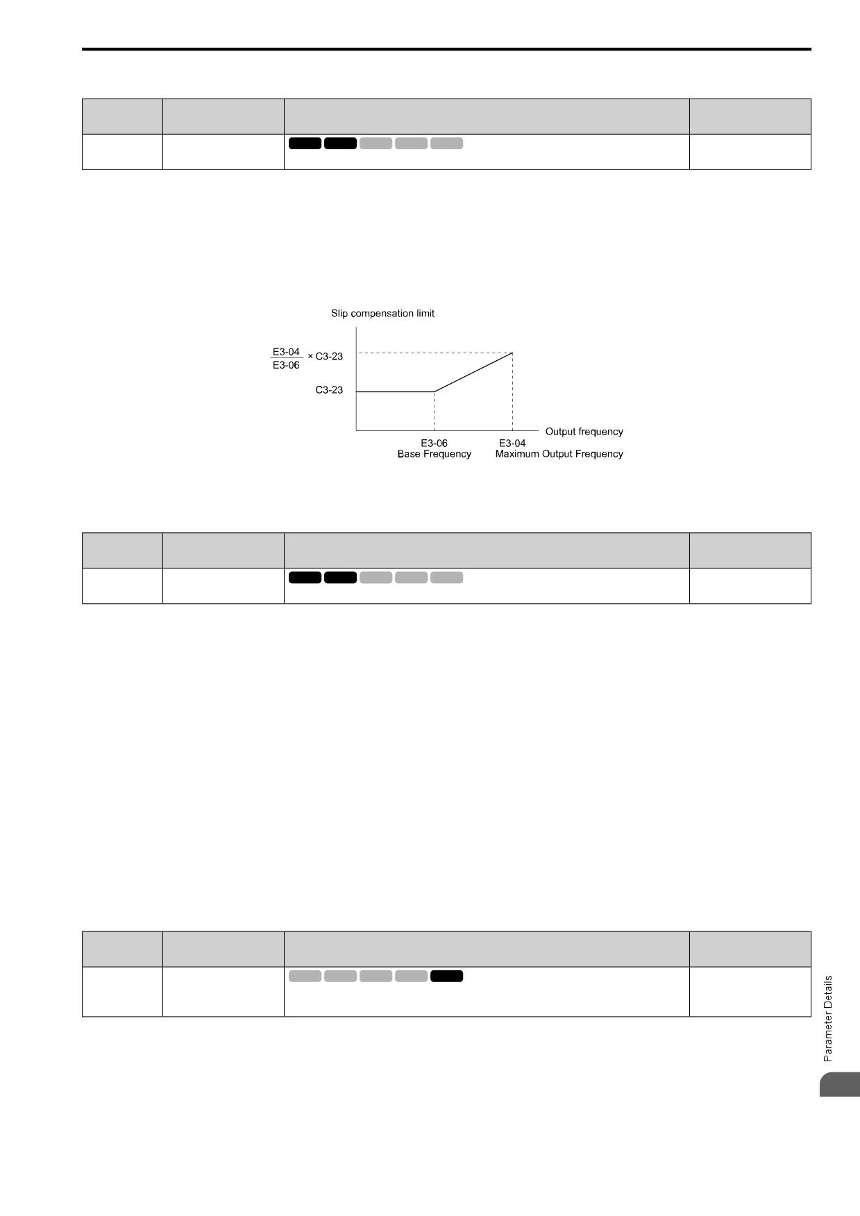
Sets the upper limit for the slip compensation function as a percentage of the motor 2 rated slip.
(0 - 250%)
If you increase the value of C3-21 [M2 Slip Comp Gain] and the motor speed is slow, use this parameter. The
drive uses this parameter when the slip is at the upper limit of slip compensation. Make sure that you measure the
motor speed when you increase this parameter value. Set this parameter to make the frequency reference and the
slip compensation limit less than the permitted range of the machine.
The slip compensation limit is constant in the constant torque range (frequency reference ≤ E3-06 [M2 Base
Frequency]). In the constant power range where the frequency reference > E3-06, the slip compensation limit
increases with the C3-23 value and the output frequency as shown.
Figure 12.43 Motor 2 Slip Compensation Limit
■ C3-24: M2 Slip Comp Regen Condition
No.
Default
Name
Description
(Hex.)
(Range)
C3-24
M2 Slip Comp Regen
V/f
OLV OLV/PM AOLV/PM EZOLV
0
Condition
(0243)
Sets the slip compensation during regenerative operation function for motor 2.
(0 - 2)
If you enable the slip compensation function during regeneration, the quantity of regeneration can increase
immediately. In this condition, it is necessary to use a dynamic braking option (braking resistor or braking resistor
unit).
0 : Disabled
The drive will not do Slip compensation during regeneration.
The load and operation status (regenerative operation) can cause the motor speed to be higher or lower than the
frequency reference.
1 : Enable>6 Hz
The slip compensation function is enabled during regeneration. Slip compensation is disabled at output
frequencies of 6 Hz or less.
2 : Enable>C3-15
The drive uses E2-02 [Mot Rated Slip] to automatically calculate the frequency range where it will disable slip
compensation function during regeneration.
Slip compensation is enabled at frequencies as low as 2 Hz.
■ C3-29: Slip Gain@Low Speed
No.
Default
Name
Description
(Hex.)
(Range)
C3-29
Slip Gain@Low Speed
V/f
OLV OLV/PM AOLV/PM EZOLV
0.0
(1B5D)
Sets the gain for the slip compensation function in the low speed range. Usually it is not necessary
(0.0
- 2.5)
to change this setting.
Expert
Adjust this parameter as follows if necessary:
• If the motor speed is slower than the frequency reference, increase the setting value in 0.1 unit increments.
• If the motor speed is faster than the frequency reference, decrease the setting value in 0.1 unit increments.
12
497
12.3 C: TUNING
◆ C4: TORQUE COMPENSATION
Torque compensation is a function that increases voltage to increase output torque as compensation for
insufficient torque production at start-up or low-speed operation.
Voltage drops due to motor winding resistance cause torque generating voltage to decrease, which causes
insufficient torque. If the main circuit cable connecting the drive and motor is long, this can also cause insufficient
torque due to voltage drops.
Note:
Set the motor parameters and V/f pattern properly before setting C4 parameters.
■ C4-01: Trq Comp Gain
No.
Default
Name
Description
(Hex.)
(Range)
C4-01
Trq Comp Gain
V/f
OLV OLV/PM AOLV/PM EZOLV
Determined by A1-02
(0215)
Sets the gain for the torque compensation function. Use this parameter value for motor 1 when
(0.00
- 2.50)
operating multiple motors.
RUN
For these control methods and states, adjust the setting value.
A1-02 [Control Method]
Status
Adjustment
Torque is not sufficient during low-speed operation of 10 Hz or less.
Increase the setting in 0.05-unit increments.
0 [V/f Control]
There is vibration in the motor or the motor hunts when operating the
Decrease the setting in 0.05-unit decrements.
8 [EZ Vector]
drive with a light load.
The cable length between the drive and motor is too long.
Increase the setting in 0.05-unit increments.
Note:
• Adjust C4-01 to make sure that output current is not more than the drive rated current while the drive operates at low speed.
• When A1-02 = 2 [OLVector], do not change this parameter under normal conditions. Torque accuracy will decrease.
• When A1-02 = 5 [PM OLVector], do not change this parameter under normal conditions. Setting this value too high can cause
overcompensation and motor oscillation.
• When A1-02 = 8 [EZ Vector], you cannot change this parameter during drive run.
■ C4-02: Trq Comp Delay Time
No.
Default
Name
Description
(Hex.)
(Range)
C4-02
Trq Comp Delay Time
V/f
OLV OLV/PM AOLV/PM EZOLV
Determined by A1-02
(0216)
Sets the torque compensation delay time. Usually it is not necessary to change this setting.
(0 - 60000 ms)
RUN
Note:
If A1-02 = 8 [Control Method = EZ Vector], you cannot change the setting while the drive is running.
Set this parameter in these conditions:
• If there is vibration in the motor, increase the setting.
• If the motor speed or motor torque response is too slow, decrease the setting.
■ C4-03: Trq Comp@FWD Start
No.
Default
Name
Description
(Hex.)
(Range)
V/f
OLV OLV/PM AOLV/PM EZOLV
C4-03
Trq Comp@FWD Start
0.0%
(0217)
Set the amount of torque reference for forward start as a percentage of the motor rated torque.
(0.0
- 200.0%)
The torque compensation function is performed using the time constant set in C4-05 [Trq Comp Time].
This is available only when you start the motor with the forward command. Set this parameter to 0.0 to disable
this function.
■ C4-04: Trq Comp@REV Start
No.
Default
Name
Description
(Hex.)
(Range)
C4-04
Trq Comp@REV Start
V/f
OLV OLV/PM AOLV/PM EZOLV
0.0%
(0218)
Sets the amount of torque reference for reverse start as a percentage of the motor rated torque.
(-200.0 - 0.0%)
498
12.3 C: TUNING
The drive uses the time constant set in C4-05 [Trq Comp Time] to do the torque compensation function.
This is available only when you start the motor with the reverse Run command.
■ C4-05: Trq Comp Time
No.
Default
Name
Description
(Hex.)
(Range)
C4-05
Trq Comp Time
V/f
OLV OLV/PM AOLV/PM EZOLV
10 ms
(0219)
Sets the starting torque constant to use with C4-03 and C4-04 [Trq Comp@FWD Start and Trq
(0 - 200 ms)
Comp@REV Start].
■ C4-06: M2 Trq Comp Delay Time
No.
Default
Name
Description
(Hex.)
(Range)
V/f
OLV OLV/PM AOLV/PM EZOLV
C4-06
M2 Trq Comp Delay Time
150 ms
(021A)
Sets the value if ov [Overvoltage] occurs with sudden changes in the load, at the end of
(0 - 10000 ms)
acceleration, or at the start of deceleration.
Sets the time constant used during Speed Search or during regenerative operation when ov occurs.
Adjust this parameter in the following circumstances.
• Gradually reduce the setting in 10 ms increments and check the performance to improve motor torque speed
response when ov occurs.
Note:
• Ensure that C4-06 ≥ C4-02 [Trq Comp Delay Time].
• Increase the setting value of n2-03 [AFR Time 2] proportional to C4-06.
■ C4-07: M2 Trq Comp Gain
No.
Default
Name
Description
(Hex.)
(Range)
C4-07
M2 Trq Comp Gain
V/f
OLV OLV/PM AOLV/PM EZOLV
1.00
(0341)
Sets the gain for motor 2 torque compensation function when using the Motor Switch function.
(0.00
- 2.50)
RUN
In V/f Control, adjust the value in 0.05-unit increments for these conditions:
• When torque is not sufficient during low-speed operation of 10 Hz or less, increase the setting value
• When there is vibration in the motor or when the motor hunts when operating the drive with a light load,
decrease the setting value
• When you use a long motor cable, increase the setting value.
Note:
• Adjust C4-07 to make sure that the output current is not more than the drive rated current during low-speed operation.
• When A1-02 = 2 [Control Method = OLVector], usually it is not necessary to change the setting. Torque accuracy will decrease.
■ C4-23: Current Ctrl Gain
No.
Default
Name
Description
(Hex.)
(Range)
C4-23
Current Ctrl Gain
V/f
OLV OLV/PM AOLV/PM EZOLV
1.00
(1583)
Current control gain. Usually it is not necessary to change this parameter.
(0.50
- 2.50)
RUN
Expert
◆ C5: ASR - SPEED REGULATION
The ASR adjusts the torque reference to decrease the difference between frequency reference and motor speed.
A1-02 [Control Method]
Targets of Adjustment
•
6: PM AOLVector
Torque Reference
•
8: EZ Vector
Figure 12.44 is a speed control block diagram of each control method.
12
499
12.3 C: TUNING
Figure 12.44 Speed Control Block Diagram for AOLV/PM and EZOLV
Note:
The detected speed is the speed estimation value when configured such that A1-02 = 6 or 8 [PM AOLVector = PM AOLVector or EZ
Vector].
■ Before You Adjust ASR Parameters
• Do Auto-Tuning and set up all motor data correctly.
• Always make adjustments with the load connected to the motor.
• Use analog output signals to monitor U1-16 [SFS Output Frequency] and U1-05 [Motor Speed] when you
adjust the ASR.
■ ASR Adjustment Procedure for AOLV/PM and EZOLV
Do this procedure to adjust ASR parameters:
1. Run the motor at zero speed or low speed and increase C5-01 [ASR PGain 1] until immediately before
vibration starts to occur.
2. Run the motor at zero speed or low speed and decrease C5-02 [ASR ITime 1] until immediately before
vibration starts to occur.
3. Check for oscillation when you run the motor at maximum speed.
4. If oscillation occurs, increase C5-02 and decrease C5-01.
When there is no oscillation, the adjustment procedure is complete.
5. Set the low-speed gain. Run the motor at zero speed or low speed and increase C5-03 [ASR PGain 2] until
immediately before vibration starts to occur.
Figure 12.45 Low-speed/High-speed Gain Settings
6. Set the low-speed integral time. Run the motor at zero speed or low speed and decrease C5-04 [ASR ITime 2]
until immediately before vibration starts to occur.
7. Set C5-07 [ASR Gain Switch Frequency].
8. Check for oscillation when you run the motor at speeds more than the setting in C5-07.
Note:
• If overshooting occurs when acceleration ends, decrease the value set in C5-01 and increase the value set in C5-02.
• If undershoot occurs at stop, decrease C5-03 and increase C5-04.
■ Use MFDI Switch for Proportional Gain
You can use the input terminals set for ASR Gain (C5-03) Select [H1-xx = 45] to switch the proportional gains set
with C5-01 and C5-03. When the configured input terminal is deactivated, the proportional gain set for C5-01 is
selected. When the terminal is activated, the proportional gain set for C5-03 is selected. The proportional gain
changes linearly over the time set in C5-02 [ASR ITime 1]. The signals from this MFDI are more important than
C5-07 [ASR Gain Switch Frequency].
500
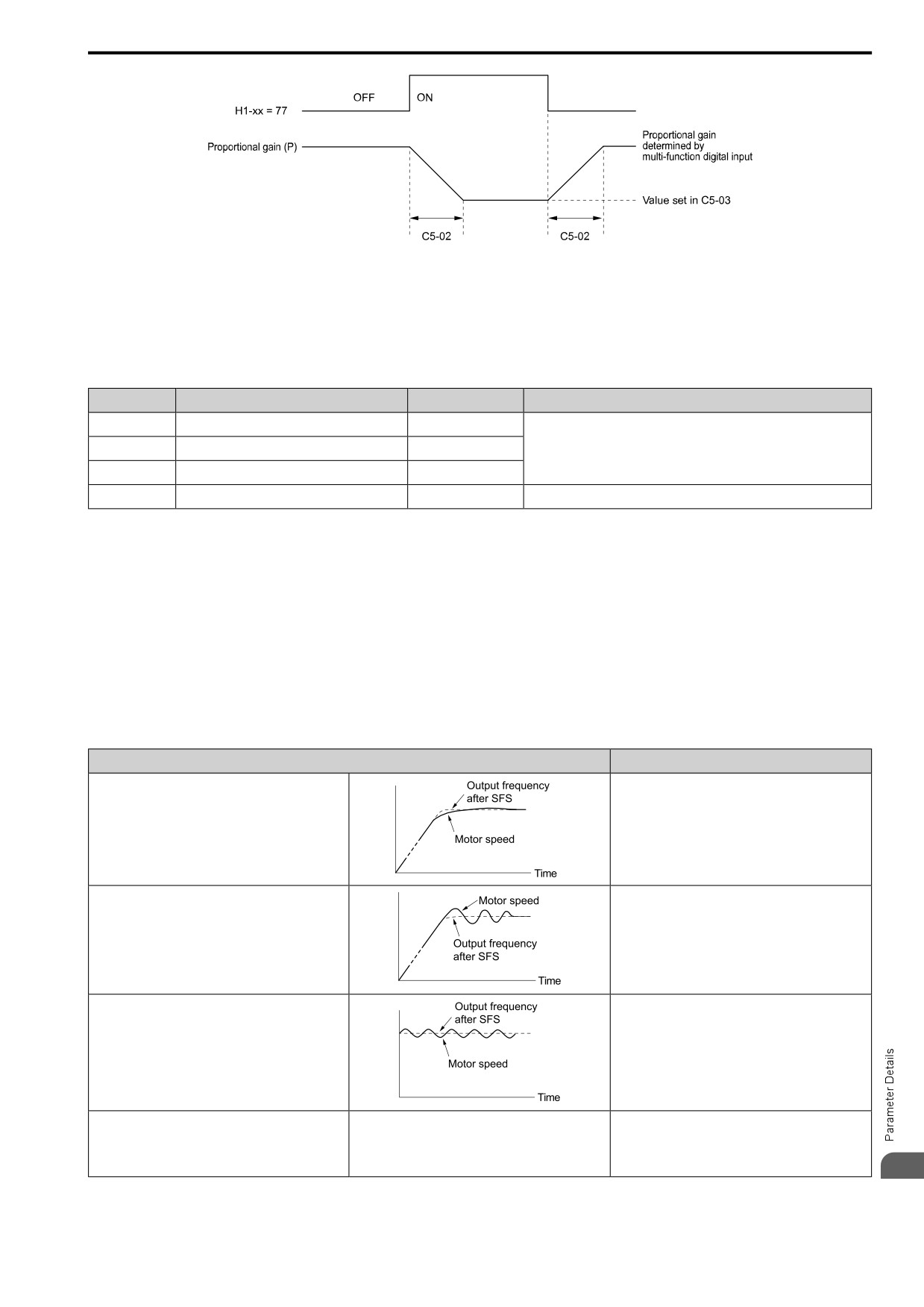
12.3 C: TUNING
Figure 12.46 Proportional Gain through Multi-function Digital Input Switch
■ Speed Waveform Monitoring Method
To make small adjustments of ASR parameters, monitor the speed waveforms when you make the adjustments.
Table 12.21 shows example settings of parameters to monitor speed waveforms.
Table 12.21 Example Settings of MFAO Terminals to Monitor Speed Waveforms
No.
Name
Setting Value
Description
H4-01
AO An.Out Select
116
Lets you use terminal AM to monitor U1-16 [SFS Output Frequency].
H4-02
AO An.Out Gain
100.0%
H4-03
AO An.Out Bias
0.0%
H4-07
AO Signal Level Select
0
Lets you monitor in a 0 V to 10 V range.
Based on this setting, MFAO terminal AM outputs the output frequency after SFS in a 0 V to 10 V (0% to 100%)
range. The MFAO common is terminal A0V:
The manufacturer recommends that you monitor the output frequency after SFS and the motor speed for delays in
response and differences in reference values.
■ Adjust ASR Parameters
Use Table 12.22 to adjust ASR. The table lists parameters for motor 1. You can make the same changes to motor 2
parameters when you run a second motor.
Note:
When adjusting the proportional gain and integral time, adjust the proportional gain first.
Table 12.22 ASR Response and Possible Solutions
Problem
Possible Solutions
• Increase C5-01/C5-03 [ASR PGain 1/ASR PGain 2].
• Decrease C5-02/C5-04 [ASR ITime 1/ASR ITime 2].
Speed response is slow.
• Decrease C5-01/C5-03.
• Increase C5-02/C5-04.
Overshoot or undershoot occurs at the end of acceleration
or deceleration.
• Decrease C5-01/C5-03.
• Increase C5-02/C5-04.
• Increase C5-06 [ASR Delay Time].
Vibration and oscillation occur at constant speed.
Oscillation at low speed and response is too slow at high
When A1-02 = 6 [Control Method = PM AOLVector], use
speed.
C5-01 to C5-04 to set the best ASR settings for high and
-
low speed. Use C5-07 [ASR Gain Switch Frequency] to
Oscillation at high speed and response is too slow at low
switch the ASR proportional gain and ASR integral time
speed.
as specified by the output frequency.
12
501
12.3 C: TUNING
■ C5-01: ASR PGain 1
No.
Default
Name
Description
(Hex.)
(Range)
C5-01
ASR PGain 1
V/f
OLV OLV/PM AOLV/PM EZOLV
Determined by A1-02
(021B)
Sets the gain to adjust ASR response.
(0.00
- 300.00)
RUN
A higher gain provides a higher speed response. Usually, the gain increases with larger loads. Too much gain will
cause vibration.
Note:
• When A1-02 = 0 [Control Method = V/f Control], set H6-01 = 3 [PI Pulse Train Function = PG Feedback] to enable this parameter.
• The drive usually sets Motor 1 ASR with C5-01 and C5-02 [ASR ITime 1]. When you set H1-xx = 45 [MFDI Function Select = ASR
Gain Switch], you can switch between C5-01 and C5-03 [ASR PGain 2]. You can also use C5-01 as an alternative to C5-03 and C5-02
as an alternative to C5-04 when the speed is less than or equal to the frequency set in C5-07 [ASR Gain Switch Frequency].
• The drive automatically adjusts C5-01 in ASR Tuning.
■ C5-02: ASR ITime 1
No.
Default
Name
Description
(Hex.)
(Range)
C5-02
ASR ITime 1
V/f
OLV OLV/PM AOLV/PM EZOLV
Determined by A1-02
(021C)
Sets the ASR integral time.
(0.000 - 60.000 s)
RUN
When you increase the integral time, the responsiveness will decrease. An integral time that is too short can cause
oscillation.
Note:
When A1-02 = 0 [Control Method = V/f Control], set H6-01 = 3 [PI Pulse Train Function = PG Feedback] to enable this parameter.
■ C5-03: ASR PGain 2
No.
Default
Name
Description
(Hex.)
(Range)
C5-03
ASR PGain 2
V/f
OLV OLV/PM AOLV/PM EZOLV
Determined by A1-02
(021D)
Sets the gain to adjust ASR response.
(0.00
- 300.00)
RUN
A higher gain provides a higher speed response. Usually, the gain increases with larger loads. Too much gain will
cause vibration.
Note:
When A1-02 = 0 [Control Method = V/f Control], set H6-01 = 3 [PI Pulse Train Function = PG Feedback] to enable this parameter.
■ C5-04: ASR ITime 2
No.
Default
Name
Description
(Hex.)
(Range)
C5-04
ASR ITime 2
V/f
OLV OLV/PM AOLV/PM EZOLV
Determined by A1-02
(021E)
Sets the ASR integral time.
(0.000 - 60.000 s)
RUN
When you increase the integral time, the responsiveness will decrease. An integral time that is too short can cause
oscillation.
Note:
When A1-02 = 0 [Control Method = V/f Control], set H6-01 = 3 [PI Pulse Train Function = PG Feedback] to enable this parameter.
■ C5-05: ASR Limit
No.
Default
Name
Description
(Hex.)
(Range)
C5-05
ASR Limit
V/f
OLV OLV/PM AOLV/PM EZOLV
5.0%
(021F)
Sets the ASR output limit where E1-04 [Max Output Frequency] is 100%.
(0.0
- 20.0%)
If the motor rated slip is high, it is necessary to increase the setting for correct motor speed control. Use U6-04
[ASR Output] to make sure that ASR is operating at the limit set in this parameter. When ASR is operating at the
limit, correctly set the encoder (PG) signal before you make changes to C5-05.
502
12.3 C: TUNING
Note:
When A1-02 = 0 [Control Method = V/f Control], set H6-01 = 3 [PI Pulse Train Function = PG Feedback] to enable this parameter.
■ C5-06: ASR Delay Time
No.
Default
Name
Description
(Hex.)
(Range)
C5-06
ASR Delay Time
V/f
OLV OLV/PM AOLV/PM EZOLV
Determined by A1-02
(0220)
Sets the filter time constant of the torque reference output from the speed loop. Usually it is not
(0.000 - 0.500 s)
necessary to change this setting.
If you have a load with low rigidity or if oscillation is a problem, decrease C5-01 in 2-unit decrements or decrease
C5-06 in 0.001-unit decrements.
■ C5-07: ASR Gain Switch Frequency
No.
Default
Name
Description
(Hex.)
(Range)
C5-07
ASR Gain Switch
V/f
OLV OLV/PM AOLV/PM EZOLV
Determined by A1-02
Frequency
(0221)
Sets the frequency where the drive will switch between these parameters:
(Determined by A1-02)
C5-01 and C5-03 [ASR PGain 1 and ASR PGain 2]
C5-02 and C5-04 [ASR ITime 1 and ASR ITime 2]
Switching the proportional gain and integral time in the low or high speed range can help operation become
stable. A good switching point is 80% of the frequency where oscillation occurs or at 80% of the maximum output
frequency.
Note:
An MFDI set for H1-xx = 45 [MFDI Function Select = ASR Gain Switch] will have priority over the ASR gain switching frequency.
■ C5-08: ASR Integral Limit
No.
Default
Name
Description
(Hex.)
(Range)
C5-08
ASR Integral Limit
V/f
OLV OLV/PM AOLV/PM EZOLV
400%
(0222)
Set the upper limit of the ASR integral amount as a percentage of the rated load.
(0 - 400%)
■ C5-12: Integral@Ac/Dec Operation
No.
Default
Name
Description
(Hex.)
(Range)
C5-12
Integral@Ac/Dec Operation
V/f
OLV OLV/PM AOLV/PM EZOLV
0
(0386)
Sets ASR integral operation during acceleration and deceleration.
(0, 1)
Set this parameter to 1 to keep the motor speed near the frequency reference during operation and acceleration/
deceleration.
Note:
• When A1-02 = 0 [Control Method = V/f Control], set H6-01 = 3 [PI Pulse Train Function = PG Feedback] to enable this parameter.
• If you enable integral control, overshoot or undershoot can occur when acceleration or deceleration complete. If there are problems
with overshooting and undershooting, set this parameter to 0.
0 : Disabled
The drive will not enable integral operation during acceleration or deceleration. The drive always enables integral
operation during constant speed.
1 : Enabled
Integral operation is always enabled.
■ C5-29: Speed Ctrl Response Mode
No.
Default
Name
Description
(Hex.)
(Range)
C5-29
Speed Ctrl Response Mode
V/f
OLV OLV/PM AOLV/PM EZOLV
1
(0B18)
Sets the level of speed control responsiveness. Usually it is not necessary to change this setting.
(0, 1)
Expert
If a high level of speed control responsiveness is necessary, set C5-29 = 1, then adjust the speed control (ASR)
12
parameter.
0 : Standard
503
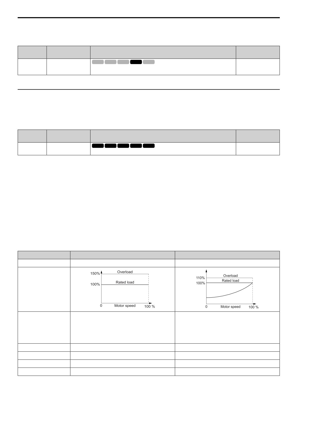
12.3 C: TUNING
1 : High Perf 1
■ C5-39: ASR Delay Time 2
No.
Default
Name
Description
(Hex.)
(Range)
C5-39
ASR Delay Time 2
V/f
OLV OLV/PM AOLV/PM EZOLV
0.000 s
(030D)
Sets the filter time constant used when the torque reference is output from ASR. Usually it is not
(0.000 - 0.500 s)
necessary to change this parameter.
If you have a load with low rigidity or if oscillation is a problem, increase this setting in 0.01 unit increments.
◆ C6: DUTY AND CARRIER
C6 parameters are used to set the selection of drive duty rating, selection of carrier frequency, and upper and
lower limits of carrier frequencies.
■ C6-01: ND/HD Duty Selection
No.
Default
Name
Description
(Hex.)
(Range)
C6-01
ND/HD Duty Selection
V/f
OLV OLV/PM AOLV/PM EZOLV
0
(0223)
Sets the drive duty rating.
(0, 1)
0 : HD Rating
The overload tolerance is 150% of the rated output current for 60 seconds.
1 : ND Rating
The overload tolerance is 110% of the rated output current for 60 seconds.
There are two types of load ratings for this product depending on the load characteristics of the application: Heavy
Duty Rating (HD) and Normal Duty Rating (ND).
The drive rated output current, overload tolerance, and acceleration stall prevention level change when the duty
rating changes. Set the drive to agree with the duty rating of the selected drive capacity. In HD, the tolerance is
150% overload for 60 seconds. In ND, the tolerance is 110% overload for 60 seconds. The rated output current for
ND drives is higher than the rated output current for HD drives. Refer to Model Specifications (Three-Phase 200
V Class) on page 292, Model Specifications (Single-Phase 200 V Class) on page 295, and Model Specifications
(Three-Phase 400 V Class) on page 296 for more information about the rated output current.
Table 12.23 Differences between Heavy Duty Rating and Normal Duty Rating
Item
Heavy Duty Rating (HD)
Normal Duty Rating (ND)
C6-01 Setting
0
1
Load Characteristics
A high overload tolerance is necessary during start up, acceleration,
deceleration, and equivalent conditions.
Overload tolerance is not necessary.
• Extruder
• Fan
Application
• Conveyor
• Pump
• Cranes and hoists
• Blower
• Constant torque or high overload capacity are necessary.
Overload Tolerance
150% - 60 seconds
110% - 60 seconds
Stall Prevent Level during Accel
150%
120%
Stall Prevent Level during Run
150%
120%
Carrier Frequency
2 kHz
2 kHz Swing-PWM
504
12.3 C: TUNING
Note:
• Set the stall prevention level during acceleration with L3-02 and the stall prevention level during run with L3-06.
• Changing C6-01 also changes the maximum capacity of applicable drive motors. The drive automatically changes the setting values
E2-xx and E4-xx to applicable values. The drive also automatically changes these parameters that depend on motor output:
-b8-04 [eSave Coef. Value]
-L2-03 [Min Baseblck Time]
-L3-24 [Acc@Rated Torque]
-n5-02 [Mot Inertia Acceleration Time]
■ C6-02: Carrier Frequency Selection
No.
Default
Name
Description
(Hex.)
(Range)
C6-02
Carrier Frequency Selection
V/f
OLV OLV/PM AOLV/PM EZOLV
Determined by A1-02, C6-
01, and o2-04
(0224)
Sets the carrier frequency for the transistors in the drive.
(Determined by A1-02)
Changes to the switching frequency will decrease audible noise and decrease leakage current.
Note:
Increasing the carrier frequency to more than the default setting will automatically decrease the drive current rating.
1 : 2.0 kHz
2 : 5.0 kHz (4.0 kHz for AOLV/PM)
3 : 8.0 kHz (6.0 kHz for AOLV/PM)
4 : 10.0 kHz (8.0 kHz for AOLV/PM)
5 : 12.5 kHz (10.0 kHz for AOLV/PM)
6 : 15.0 kHz (12.0 kHz AOLV/PM)
7 : Swing PWM 1 (Audible Sound 1)
8 : Swing PWM 2 (Audible Sound 2)
9 : Swing PWM 3 (Audible Sound 3)
A : Swing PWM 4 (Audible Sound 4)
B : Leakage Current Rejection PWM
Set this when the wiring distance between the drive and motor is long and there is a fault in the current monitor or
the drive detects and alarm because of the effect of a leakage current.
The carrier frequency is equivalent to 2.0 kHz.
F : User (C6-03 to C6-05)
Use C6-03 to C6-05 to set detailed setting values.
Note:
• The carrier frequency for Swing PWM 1 is equivalent to 2.0 kHz. Swing PWM applies a special PWM pattern to decrease the audible
noise.
• The setting range changes when the A1-02 [Control Method] value changes:
-5, 8 [PM OLVector, EZ Vector]: You cannot set to 7 to A.
-6 [EZ Vector]: You cannot set to 7 to A or F.
Table 12.24 Guidelines for Carrier Frequency Parameter Setup
Symptom
Remedy
Speed and torque are not stable at low speed.
Decrease the carrier frequency.
Speed and torque are not stable at low speed.
Decrease the carrier frequency.
Too much leakage current from the drive.
Decrease the carrier frequency.
Wiring between the drive and motor is too long.
Decrease the carrier frequency.
Note:
If the motor cable is too long, it can be necessary to decrease the carrier frequency. Refer to Table 12.25 for the
wiring distance and decrease the carrier frequency.
Audible motor noise is too loud.
Increase the carrier frequency. Use Swing PWM.
Note:
The default carrier frequency in ND is C6-02 = 7 [Swing PWM 1 (Audible Sound 1)], with a 2 kHz base. You can
increase the carrier frequency in Normal Duty mode, but this will also decrease the drive rated current.
12
505
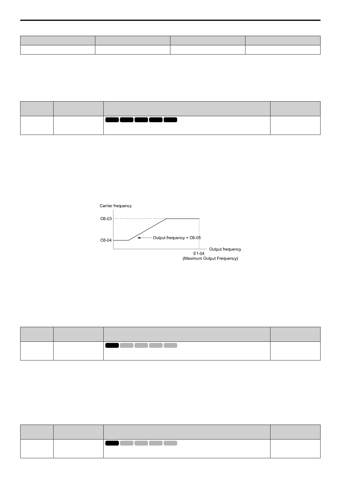
12.3 C: TUNING
Table 12.25 Wiring Distance
Wiring Distance
50 mm (164 ft) Maximum
100 m (328 ft) Maximum
More than 100 m (328 ft)
C6-02 [Carrier Frequency Selection]
1 to F (up to 15 kHz)
1 to 2 (up to 5 kHz), 7
1
(up to 2 kHz), 7
Note:
• When the wiring length is longer than 100 m (328 ft), set A1-02 = 0 [V/f Control].
• The maximum wiring cable length between the drive and a PM motor is 100 m (328 ft).
• If the cable length between the drive and the motor is too long when A1-02 = 6, set A1-02 = 5.
■ C6-03: Carrier Upper Frequency Limit
No.
Default
Name
Description
(Hex.)
(Range)
C6-03
Carrier Upper Frequency
V/f
OLV OLV/PM AOLV/PM EZOLV
Determined by C6-02
Limit
(0225)
Sets the upper limit of the carrier frequency. Set C6-02 = F [Carrier Frequency Selection = User
(1.0 - 15.0 kHz)
(C6-03 to C6-05)] to set this parameter.
Setting a Fixed User-Defined Carrier Frequency
When you cannot use C6-02 to set a carrier frequency between set selectable values, you can set the value in C6-
03. The carrier frequency will be fixed to the value set to C6-03.
When A1-02 = 0 [Control Method = V/f Control], set C6-03 = C6-04 [Carrier Lower Frequency Limit] to fix the
carrier frequency.
Setting a Variable Carrier Frequency to Agree with the Output Frequency
When A1-02 = 0, set C6-03, C6-04, and C6-05 [Carrier Freq Proportional Gain] as shown in Figure 12.47 to
make the carrier frequency change linearly with the output frequency.
Figure 12.47 Setting a Variable Carrier Frequency to Agree with the Output Frequency
Note:
• When C6-05 ≤ 7, the drive disables C6-04. The carrier frequency is fixed to the value set to C6-03.
• The drive detects oPE11 [Carrier Frequency Setting Error] when these conditions are correct at the same time:
-C6-05 ≥ 6
-C6-04 ≥ C6-03
■ C6-04: Carrier Lower Frequency Limit
No.
Default
Name
Description
(Hex.)
(Range)
C6-04
Carrier Lower Frequency
V/f
OLV OLV/PM AOLV/PM EZOLV
Determined by C6-02
Limit
(0226)
Sets the lower limit of the carrier frequency. Set C6-02 = F [Carrier Frequency Selection = User
(1.0 - 15.0 kHz)
(C6-03 to C6-05)] to set this parameter.
Set C6-03 [Carrier Upper Frequency Limit], C6-04, and C6-05 [Carrier Freq Proportional Gain] to make the
carrier frequency change linearly with the output frequency.
Note:
The drive detects oPE11 [Carrier Frequency Setting Error] when these conditions are correct at the same time:
• C6-04 ≥ C6-03
• C6-05 ≥ 6
■ C6-05: Carrier Freq Proportional Gain
No.
Default
Name
Description
(Hex.)
(Range)
C6-05
Carrier Freq Proportional
V/f
OLV OLV/PM AOLV/PM EZOLV
Determined by C6-02
Gain
(0227)
Sets the proportional gain for the carrier frequency. Set C6-02 = F [Carrier Frequency Selection
(0 - 99)
= User (C6-03 to C6-05)] to set this parameter.
506
12.3 C: TUNING
Set C6-03 [Carrier Upper Frequency Limit], C6-04 [Carrier Lower Frequency Limit], and C6-05 to make the
carrier frequency change linearly with the output frequency.
■ C6-09: Carrier@Autotune Rotational
No.
Default
Name
Description
(Hex.)
(Range)
C6-09
Carrier@Autotune
V/f
OLV OLV/PM AOLV/PM EZOLV
0
Rotational
(022B)
Sets the Auto-Tuning carrier frequency. Usually it is not necessary to change this setting.
(0, 1)
If C6-09 = 0 and you do Auto-Tuning on a high frequency motor or low impedance motor, it can cause oC
[Overcurrent]. To prevent oC, increase the carrier frequency value, set C6-09 = 1, then do Auto-Tuning.
The procedure to set the carrier frequency when the A1-02 [Control Method] setting changes.
• When A1-02 = 2 [OLVector], set C6-02 = F [Carrier Frequency Selection = User (C6-03 to C6-05)] and then
increase the value set to C6-03 [Carrier Upper Frequency Limit].
• When A1-02 = 5 or 6 [PM OLVector or PM AOLVector], use C6-02 to increase the carrier frequency.
0 : 5 kHz
Note:
When A1-02 = 5 or 6, the carrier frequency is 2 kHz.
1 : use C6-03
Note:
When A1-02 = 5 or 6, the carrier frequency is the value set to C6-02.
12
507
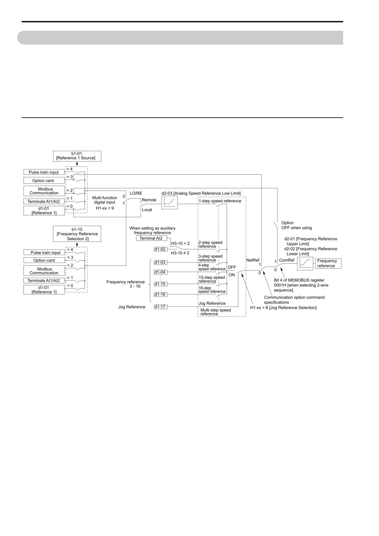
12.4 d: REFERENCE
12.4
d: REFERENCE
d parameters set the frequency reference input method and dead band range. They also set torque control, field
weakening, and field forcing functions.
WARNING! Sudden Movement Hazard. Use fast stop circuits to safely and quickly stop the drive. After you wire the fast stop
circuits, you must check their operation. Test the operation of the fast stop function before you use the drive. If you do not test
the fast stop circuit before you operate the drive, it can cause serious injury or death.
WARNING! Sudden Movement Hazard. When you use the drive in a lifting application, you must also install external safety
circuitry. The drive does not have protection against accidental load drops in lifting applications. Install electrical and/or
mechanical safety circuit mechanisms that are isolated from the drive circuitry. If you do not use external safety circuitry, the
drive could drop the load and cause serious injury or death.
◆ d1: FREQUENCY REFERENCE
Figure 12.48 shows the frequency reference input method, command source selection method, and priority
descriptions.
Figure 12.48 Frequency Reference Setting Hierarchy
■ Multi-Step Speed Operation
The drive has a multi-step speed operation function that can set many frequency references in advance. Set
frequency references in d1-xx parameters. You can select the set frequency references with MFDI signals from an
external source. Activate and deactivate the digital input to select the frequency reference to change the motor
speed in steps. You can use the 16-step frequency reference and one Jog Frequency Reference (JOG command) to
switch the speed to the maximum 17-step speeds.
Note:
• The Jog Frequency Reference (JOG command) overrides all other frequency references.
• You can use the MFDI to switch the frequency reference when the motor is running. The drive will apply the enabled acceleration and
deceleration times.
• The default settings for Multi-Step Speed Reference 1 (master frequency reference) and Multi-Step Speed Reference 2 (auxiliary
frequency reference) are the analog frequency reference.
Also, voltage command input terminal AI1 and current input terminal AI2 for Multi-Step Speed Reference 1 (master frequency
reference) are added internally by default. The drive uses Multi-Step Speed Reference 1 when the signal is connected to an analog
input terminal.
■ Setting Procedures for Multi-step Speed Operation
Use an Analog Input as Reference 1 and 2
This section gives information about the procedures to set these examples:
• Multi-Step Speed 6 (6 types of frequency references)
508
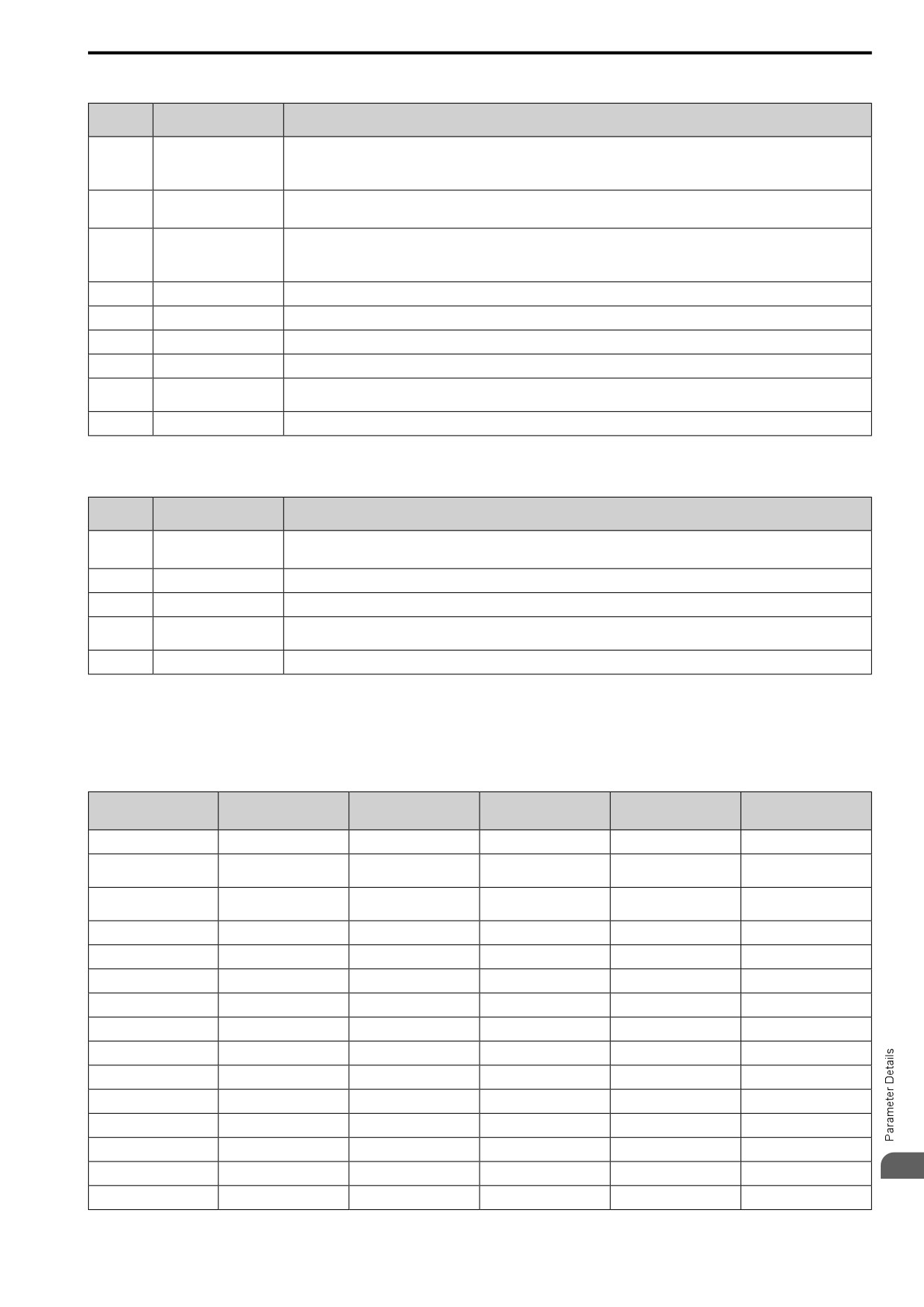
12.4 d: REFERENCE
• When you set the voltage input of analog inputs from terminals AI1 and AI2 to 0 V to 10 V (Lower Limit at 0)
Configuration
Procedure
Task Contents
Parameter
1
Reference 1
1.
Sets b1-01 = 1 [Freq. Ref. Sel. 1 = Analog Input].
2.
Sets H3-02 = 3 [AI1 Function Selection = FrqBIAS Frq].
3.
Sets H3-01 = 0 [AI1 Signal Level Select = 0 to 10V (Lower Limit at 0)].
2
Reference 2
1.
Sets H3-10 = 1 [AI2 Function Selection = AuxFreqRef1].
2.
Sets H3-09 = 0 [AI2 Signal Level Select = 0 to 10V (Lower Limit at 0)].
3
Signal type of analog input
Set DIP switch S1 on the control circuit board to the V-side (voltage) to set terminal AI2 only for voltage input.
Note:
Set this before you energize the drive.
4
Reference 3
Sets the value of d1-03 [Reference 3].
5
Reference 4
Sets the value of d1-04 [Reference 4].
6
Reference 5
Sets the value of d1-05 [Reference 5].
7
Jog Reference
Sets d1-17 [Jog Reference] to the jog speed.
8
External digital input (3
Set the Multi-Step Speed Reference 1 to 3 [H1-xx = A, B, C] to one of the MFDI terminals DI1 to DI7.
inputs)
9
JOG command
Set the Jog Reference [H1-xx = 6] to one of the MFDI terminals DI1 to DI7.
Use the Maximum 17-Step Speed with All Digital Inputs
This section is the procedure to set the 17-step speeds (17 types of frequency references) without an analog input.
Configuration
Procedure
Task Contents
Parameter
1
Analog reference
1.
Sets H3-02 = 0 [AI1 Function Selection = Through Mode], and disables the analog reference.
2.
Sets H3-10 = 0 [AI2 Function Selection = Through Mode], and disables the analog reference.
2
Reference 2 to 16
Sets the values of d1-02 to d1-16 [Reference 2 to Reference 16].
3
Jog Reference
Sets d1-17 [Jog Reference] to the jog speed.
4
External digital input (4
Set Multi-Step Speed Reference 1 to 4 [H1-xx = A, B, C, D] to one of the MFDI terminals DI1 to DI7.
inputs)
5
JOG command
Set the Jog Reference [H1-xx = 6] to one of the MFDI terminals DI1 to DI7.
Multi-step Speed Operation Combinations
Refer to Table 12.26 and Figure 12.49 for information about multi-step speed reference combinations. The
selected frequency reference changes when the combination of digital input signals from an external source
changes.
Table 12.26 Multi-step Speed Reference and MFDI Terminal Combinations
MultSpd Ref1
MultSpd Ref2
MultSpd Ref3
MultSpd Ref4
Jog Reference
Related Parameters
H1-xx = A
H1-xx = B
H1-xx = C
H1-xx = D
H1-xx = 6
Reference 1 (set in b1-01)
OFF
OFF
OFF
OFF
OFF
Reference 2 (d1-02 or
ON
OFF
OFF
OFF
OFF
terminals AI1, AI2)
Reference 3 (d1-03 or
OFF
ON
OFF
OFF
OFF
terminals AI1, AI2)
Reference 4 (d1-04)
ON
ON
OFF
OFF
OFF
Reference 5 (d1-05)
OFF
OFF
ON
OFF
OFF
Reference 6 (d1-06)
ON
OFF
ON
OFF
OFF
Reference 7 (d1-07)
OFF
ON
ON
OFF
OFF
Reference 8 (d1-08)
ON
ON
ON
OFF
OFF
Reference 9 (d1-09)
OFF
OFF
OFF
ON
OFF
Reference 10 (d1-10)
ON
OFF
OFF
ON
OFF
Reference 11 (d1-11)
OFF
ON
OFF
ON
OFF
Reference 12 (d1-12)
ON
ON
OFF
ON
OFF
Reference 13 (d1-13)
OFF
OFF
ON
ON
OFF
12
Reference 14 (d1-14)
ON
OFF
ON
ON
OFF
Reference 15 (d1-15)
OFF
ON
ON
ON
OFF
509
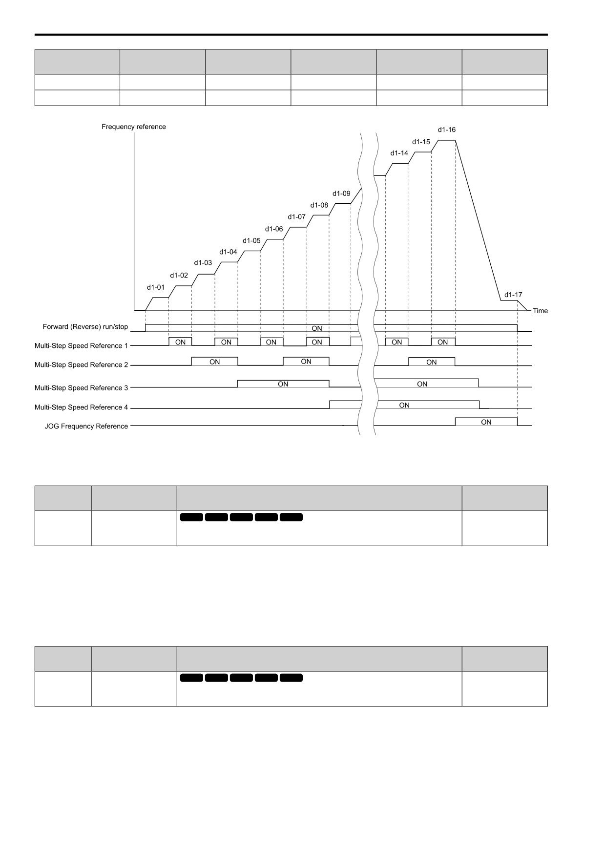
12.4 d: REFERENCE
MultSpd Ref1
MultSpd Ref2
MultSpd Ref3
MultSpd Ref4
Jog Reference
Related Parameters
H1-xx = A
H1-xx = B
H1-xx = C
H1-xx = D
H1-xx = 6
Reference 16 (d1-16)
ON
ON
ON
ON
OFF
Jog Reference (d1-17) *1
-
-
-
-
ON
*1
The Jog Frequency Reference (JOG command) overrides all other frequency references.
Figure 12.49 Time Chart for Multi-step Speed Reference/JOG Reference
■ d1-01: Reference 1
No.
Default
Name
Description
(Hex.)
(Range)
d1-01
Reference 1
V/f
OLV OLV/PM AOLV/PM EZOLV
0.00 Hz
(0280)
Sets the frequency reference in the units from o1-03 [FrqDisplay Unit Selection].
(0.00 - 590.00 Hz)
RUN
Note:
• The upper limit value changes when the E1-04 [Max Output Frequency] and d2-01 [FRef Upper Limit] values change. Calculate the
upper limit value with this formula:
Upper limit value = (E1-04) × (d2-01) / 100
• When A1-02 = 6 [Control Method = PM AOLVector], the drive sets o1-03 = 1 [0.01% (100%=E1-04)].
• To set d1-01 to 1-step speed parameter in a multi-step speed operation, set b1-01 = 0 [Freq. Ref. Sel. 1 = Keypad].
■ d1-02: Reference 2
No.
Default
Name
Description
(Hex.)
(Range)
d1-02
Reference 2
V/f
OLV OLV/PM AOLV/PM EZOLV
0.00 Hz
(0281)
Sets the frequency reference in the units from o1-03 [FrqDisplay Unit Selection].
(0.00 - 590.00 Hz)
RUN
Note:
• The upper limit value changes when the E1-04 [Max Output Frequency] and d2-01 [FRef Upper Limit] values change.
• When A1-02 = 6 [Control Method = PM AOLVector], the drive sets o1-03 = 1 [0.01% (100%=E1-04)].
• To set d1-02 to Multi-Step Speed 2, set H3-02 and H3-10 ≠ 1 [MFAI Function Select ≠ AuxFreqRef1].
510