Q2V Driving Quality. Technical Manual (Item code: Q2V-Axxxx-xxx, 2020) - page 15

12.6 F: OPTIONS
Register
Description
No. (Hex.)
15C8
Run Command (Drive 2)
15C9
Frequency Reference (Drive 2)
15CA
Run Command (Drive 3)
15CB
Frequency Reference (Drive 3)
15CC
Run Command (Drive 4)
15CD
Frequency Reference (Drive 4)
Slave Address for Reg. Access + Read/Write
Slave address
0: Broadcast Messages (Modbus)
bit 0
1: Drive 1
When bit 0 to 3 = 0, access is enabled for broadcast messages only.
bit 1
2: Drive 2
When bit 0 to 3 = 5, access is enabled for Run command and frequency reference
15CE
bit 2
3: Drive 3
broadcast messages only. Drive 0 is excluded.
bit 3
4: Drive 4
5: Broadcast Messages (run command and frequency
reference)
bit 4
0: Read, 1: Write
bit 5 - F
Reserved
15CF
Register number
15D0
Data (write register)
Table 12.36
Monitor Data
Register
Description
No. (Hex.)
Drive Status (Drive 1)
bit 0
During Run
bit 1
During Reverse Run
bit 2
Drive ready
bit 3
Fault
bit 4
Frequency Command Setting Fault
1: Upper/Lower Limit Fault
bit 5
No response from slave
1: Response has timed out.
bit 6
Communication Error
1: The drive detected a fault from a slave.
15E7
bit 7
No response from slave 10 consecutive attempts.
1: Timeout occurred 10 consecutive times.
bit 8
Communication fault occurred 10 consecutive times.
1: Fault has occurred from a slave 10 consecutive times.
bit 9
Receive broadcast command while drive is running
1: Drive operates as specified by the broadcast message command.
bit A
Communication error with master drive
1: The slave cannot communicate with the master because of a communication error.
bit B -
Reserved
D
bit E
ComRef status
bit F
ComCtrl status
Output frequency or frequency reference (Drive Status Bit 1: ON)
(Drive 1)
15E8
The unit of measure changes when o1-03 changes.
Drive Status Bit 4 = 0 [Output Frequency]
Drive Status Bit 4 = 1 [Frequency Reference]
15E9
Drive Status (Drive 2)
Output frequency or frequency reference (Drive Status Bit 4: ON)
15EA
(Drive 2)
15EB
Drive Status (Drive 3)
Output frequency or frequency reference (Drive Status Bit 4: ON)
15EC
(Drive 3)
15ED
Drive Status (Drive 4)
Output frequency or frequency reference (Drive Status Bit 4: ON)
15EE
(Drive 4)
550
12.6 F: OPTIONS
Register
Description
No. (Hex.)
Slave Address for Reg. Access + During Modbus process & ErrCode
bit 0
00H: Modbus Communication Complete
bit 1
02H: Register number not registered
bit 2
21H: Upper/Lower Limit Fault
Note:
bit 3
22H: Write Mode Error
If you change the access command before the Modbus access flag turns on, the drive
bit 4
23H: Write performed during Uv
will not do the command from before.
bit 5
24H: Write performed while writing parameter settings
bit 6
FFH: During Modbus Communication
bit 7
15EF
Slave address
0: Modbus command ignored
bit 8
1: Drive 1
bit 9
2: Drive 2
bit A
3: Drive 3
bit B
4: Drive 4
5: Broadcast Messages (run command and frequency
reference)
bit C -
Reserved
F
15F0
Register number
15F1
Data (write register)
■ F6-01: Comm.Error Selection
No.
Default
Name
Description
(Hex.)
(Range)
F6-01
Comm.Error Selection
V/f
OLV OLV/PM AOLV/PM
EZOLV
1
(03A2)
Sets the method to stop the motor or let the motor continue operating when the drive detects bUS
(0 - 5)
[Option Communication Error].
0 : Ramp->Stop
The drive ramps the motor to stop in the deceleration time. The output terminal set for Fault [H2-01 to H2-03 =
3] activates.
1 : Coast->Stop
The output turns off and the motor coasts to stop. The output terminal set for Fault [H2-01 to H2-03 = 3]
activates.
2 : Fast Stop (C1-09)
The drive stops the motor in the deceleration time set in C1-09 [Fast Stop Time]. The output terminal set for Fault
[H2-01 to H2-03 = 3] activates.
3 : Alarm Only
The keypad shows bUS and the drive continues operation at the current frequency reference.
Note:
Separately prepare safety protection equipment and systems, for example fast stop switches.
The output terminal set to Alarm [H2-01 to H2-03 = 4] activates.
4 : AL-Run at d1-04
The keypad shows bUS and the drive continues operation at the speed set in d1-04 [Reference 4].
Note:
Separately prepare safety protection equipment and systems, for example fast stop switches.
5 : AL-Ramp Stop
The drive stops the motor during the deceleration time set in C1-02 [Decel Time 1].
After you remove the bUS alarm, the motor will accelerate to the previous frequency reference.
■ F6-02: Comm Ext Flt Detect (EF0)
No.
Default
Name
Description
(Hex.)
(Range)
12
V/f
OLV OLV/PM AOLV/PM EZOLV
F6-02
Comm Ext Flt Detect (EF0)
0
(03A3)
Sets the conditions at which EF0 [Option Card External Fault] is detected.
(0, 1)
551
12.6 F: OPTIONS
0 : Always Detected
1 : Detect@RUN Only
■ F6-03: Comm Ext Flt Select (EF0)
No.
Default
Name
Description
(Hex.)
(Range)
F6-03
Comm Ext Flt Select (EF0)
V/f
OLV OLV/PM AOLV/PM EZOLV
1
(03A4)
Sets the method to stop the motor or let the motor continue operating when the drive detects EF0
(0 - 3)
[Option Card External Fault].
0 : Ramp->Stop
The drive ramps the motor to stop in the deceleration time. The output terminal set for Fault [H2-01 to H2-03 =
3] activates.
1 : Coast->Stop
The output turns off and the motor coasts to stop. The output terminal set for Fault [H2-01 to H2-03 = 3]
activates.
2 : Fast Stop (C1-09)
The drive stops the motor in the deceleration time set in C1-09 [Fast Stop Time]. The output terminal set for Fault
[H2-01 to H2-03 = 3] activates.
3 : Alarm Only
The keypad shows EF0 and the drive continues operation.
Note:
Separately prepare safety protection equipment and systems, for example fast stop switches.
The output terminal set to Alarm [H2-01 to H2-03 = 4] activates.
■ F6-04: bUS Err Det.Time
No.
Default
Name
Description
(Hex.)
(Range)
F6-04
bUS Err Det.Time
V/f
OLV OLV/PM AOLV/PM EZOLV
2.0 s
(03A5)
Sets the delay time for the drive to detect bUS [Option Communication Error].
(0.0 - 12.0 s)
Note:
When you install an option card in the drive, the parameter value changes to 0.0 s.
■ F6-06: Trq Lim Com Option
No.
Default
Name
Description
(Hex.)
(Range)
F6-06
Trq Lim Com Option
V/f
OLV OLV/PM AOLV/PM EZOLV
0
(03A7)
Sets the function that enables and disables the torque reference and torque limit received from the
(0, 1)
communication option.
0 : Disabled
1 : Enabled
■ F6-07: Multi-Ref@NetRef/ComRef
No.
Default
Name
Description
(Hex.)
(Range)
F6-07
Multi-Ref@NetRef/
V/f
OLV OLV/PM AOLV/PM EZOLV
1
ComRef
(03A8)
Sets the function that enables and disables the multi-step speed reference when the freqency
(0, 1)
reference source is NetRef or ComRef (communication option card or Modbus communications).
0 : Disable MultiStep References
When NetRef or ComRef are the frequency reference source, the multi-step speed reference (2-step speed to 16-
step speed references) and the Jog Frequency Reference (JOG command) are disabled.
1 : Enable MultiStep References
When NetRef or ComRef are the frequency reference source, the multi-step speed reference (2-step speed through
16-step speed references) and the Jog Frequency Reference (JOG command) are enabled, and you can change the
frequency reference.
552
12.6 F: OPTIONS
■ F6-08: Comm Par RST@Initialize
No.
Default
Name
Description
(Hex.)
(Range)
F6-08
Comm Par RST@Initialize
V/f
OLV OLV/PM AOLV/PM EZOLV
0
(036A)
Sets the function to initialize F6-xx and F7-xx parameters when the drive is initialized with A1-03
(0, 1)
[Initialize Parameters].
0 : Retain Pars - No Reset
1 : Factory Default - Reset
Note:
When you use A1-03 to initialize the drive, this setting will not change.
■ F6-10: CCLink Node Address
No.
Default
Name
Description
(Hex.)
(Range)
F6-10
CCLink Node Address
V/f
OLV OLV/PM AOLV/PM EZOLV
0
(03B6)
Sets the node address for CC-Link communication. Restart the drive after you change the
(0 - 64)
parameter setting.
Note:
Be sure to set a node address that is different than all other node addresses. Do not set this parameter to 0. Incorrect parameter settings
will cause AEr [Station Address Setting Error] errors and the L.ERR LED on the option will come on.
When the only drive is connected, you can connect a maximum of 42 nodes. Follow these rules to connect devices
that are not drives:
•
{(1 × a) + (2 × b) + (3 × c) + (4 × d)} ≤ 64
(a: number of units that occupies 1 node, b: number of units that occupies 2 nodes, c: number of units that
occupies 3 nodes, d: number of units that occupies 4 nodes)
•
{(16 × A) + (54 × B) + (88 × C)} ≤ 2304
(A: number of remote I/O nodes (64 max.), B: number of remote device nodes (42 max.), C: number of local
nodes (26 max.))
■ F6-11: CCLink Comm Speed
No.
Default
Name
Description
(Hex.)
(Range)
V/f
OLV OLV/PM AOLV/PM EZOLV
F6-11
CCLink Comm Speed
0
(03B7)
Sets the communication speed for CC-Link communication. Restart the drive after you change the
(0 - 4)
parameter setting.
0 : 156 kbps
1 : 625 kbps
2 : 2.5 Mbps
3 : 5 Mbps
4 : 10 Mbps
■ F6-14: BUS Err. AutoReset
No.
Default
Name
Description
(Hex.)
(Range)
F6-14
BUS Err. AutoReset
V/f
OLV OLV/PM AOLV/PM EZOLV
0
(03BB)
Sets the automatic reset function for bUS [Option Communication Errors].
(0, 1)
0 : Disabled
1 : Enabled
■ F6-15: Comm. Option Parameters Reload
No.
Default
Name
Description
(Hex.)
(Range)
F6-15
Comm. Option Parameters
V/f
OLV OLV/PM AOLV/PM EZOLV
0
Reload
(0B5B)
Sets the update method when you change F6-xx, F7-xx [F6: COMMUNICATIONS, F7:
(0 - 2)
12
ETHERNET].
553
12.6 F: OPTIONS
Note:
• Set F6-15 = 0, 1 to reload F6-xx, F7-xx.
• Set F6-15 = 0, 1 to reset the display on the keypad to 0.
0 : Reload@Next Power Cycle
Restart the drive to update parameters.
1 : Reload Now
The changed parameters are updated without restarting the drive.
2 : Cancel Reload Request
Cancels CyPo [Cycle Power to Accept Changes].
■ F6-16: Gateway Mode
No.
Default
Name
Description
(Hex.)
(Range)
F6-16
Gateway Mode
V/f
OLV OLV/PM AOLV/PM EZOLV
0
(0B8A)
Sets the gateway mode operation and the number of connected slave drives.
(0 to 4)
0 : Disabled
1 : 1 Slave Drive
2 : 2 Slave Drives
3 : 3 Slave Drives
4 : 4 Slave Drives
■ F6-20: MLII Address
No.
Default
Name
Description
(Hex.)
(Range)
F6-20
MLII Address
V/f
OLV OLV/PM AOLV/PM EZOLV
0021h
(036B)
Sets the station address for MECHATROLINK communication. Change the parameter then cycle
(MECHATROLINK-II:
power on the drive.
0020h - 003Fh,
MECHATROLINK-III:
0003h - 00EFh)
Note:
• The setting range changes if using MECHATROLINK-II or MECHATROLINK-III:
-MECHATROLINK-II (SI-T3) range: 20 to 3F
-MECHATROLINK-III (SI-ET3) range: 03 to EF
• Be sure to set a node address that is different than all other node addresses. Incorrect parameter settings will cause AEr [Station
Address Setting Error] errors and the L.ERR LED on the option will come on.
• The drive detects AEr errors when the station address is 20 or 3F.
■ F6-21: MLII Frame Size
No.
Default
Name
Description
(Hex.)
(Range)
F6-21
MLII Frame Size
V/f
OLV OLV/PM AOLV/PM EZOLV
0
(036C)
Sets the frame size for MECHATROLINK communication. Restart the drive after you change the
(0, 1)
parameter setting.
0 : 32-byte
1 : 17-byte
■ F6-22: MLII Link Speed
No.
Default
Name
Description
(Hex.)
(Range)
F6-22
MLII Link Speed
V/f
OLV OLV/PM AOLV/PM EZOLV
0
(036D)
Sets the communications speed for MECHATROLINK-II. Restart the drive after you change the
(0, 1)
parameter setting.
Note:
This parameter is only available with the MECHATROLINK-II option.
0 : 10 Mbps
1 : 4 Mbps
554
12.6 F: OPTIONS
■ F6-23: MLII Mon Sel (E)
No.
Default
Name
Description
(Hex.)
(Range)
F6-23
MLII Mon Sel (E)
V/f
OLV OLV/PM AOLV/PM EZOLV
0000h
(036E)
Sets the Modbus register used for the monitor functions of INV_CTL (drive operation control
(0000h - FFFFh)
command) and INV_I/O (drive I/O control command). Restart the drive after you change the
parameter setting.
To enable the Modbus register set in F6-23, set SEL_MON2/1 to 0EH or set SEL_MON 3/4 and SEL_MON 5/6
to 0EH. Bytes of the response data enable the Modbus register content that was set in F6-23.
■ F6-24: MLII Mon Sel (F)
No.
Default
Name
Description
(Hex.)
(Range)
F6-24
MLII Mon Sel (F)
V/f
OLV OLV/PM AOLV/PM EZOLV
0000h
(036F)
Sets the Modbus register used for the monitor functions of INV_CTL (drive operation control
(0000h - FFFFh)
command) and INV_I/O (drive I/O control command). Restart the drive after you change the
parameter setting.
To enable the Modbus register set in F6-24, set SEL_MON2/1 to 0FH or set SEL_MON3/4 and SEL_MON 5/6 to
0FH. Bytes of the response data enable the Modbus register content that was set F6-24.
■ F6-25: MLII Watchdog Error Sel
No.
Default
Name
Description
(Hex.)
(Range)
F6-25
MLII Watchdog Error Sel
V/f
OLV OLV/PM AOLV/PM EZOLV
1
(03C9)
Sets the method to stop the motor or let the motor continue operating when the drive detects E5
(0 - 3)
[MECHATROLINK Watchdog Timer Err].
0 : Ramp->Stop
The drive ramps the motor to stop in the deceleration time. The output terminal set for Fault [H2-01 to H2-03 =
3] activates.
1 : Coast->Stop
The output turns off and the motor coasts to stop. The output terminal set for Fault [H2-01 to H2-03 = 3]
activates.
2 : Fast Stop (C1-09)
The drive stops the motor in the deceleration time set in C1-09 [Fast Stop Time]. The output terminal set for Fault
[H2-01 to H2-03 = 3] activates.
3 : Alarm Only
The keypad shows E5, and the drive continues to operate.
Note:
Separately prepare safety protection equipment and systems, for example fast stop switches.
The output terminal set to Alarm [H2-01 to H2-03 = 4] activates.
■ F6-26: MLII bUS Err Detected
No.
Default
Name
Description
(Hex.)
(Range)
F6-26
MLII bUS Err Detected
V/f
OLV OLV/PM AOLV/PM EZOLV
2
(03CA)
Sets the number of times that the option must detect a bUS alarm to cause a bUS [Option
(2 - 10 times)
Communication Error].
■ F6-30: PROFI-DP Address
No.
Default
Name
Description
(Hex.)
(Range)
F6-30
PROFI-DP Address
V/f
OLV OLV/PM AOLV/PM EZOLV
0
(03CB)
Sets the node address for PROFIBUS-DP communication. Restart the drive after you change the
(0 - 125)
parameter setting.
Note:
12
• Be sure to set a node address that is different than all other node addresses.
• Node addresses 0, 1, and 2 are usually reserved for control, maintenance, and device self-diagnosis.
555
12.6 F: OPTIONS
■ F6-31: PROFI-DP Clear Command Mode
No.
Default
Name
Description
(Hex.)
(Range)
F6-31
PROFI-DP Clear Command
V/f
OLV OLV/PM AOLV/PM EZOLV
0
Mode
(03CC)
Sets what the drive will do after it receives the Clear Mode command.
(0, 1)
0 : Reset
Resets drive settings, for example frequency reference and I/O settings.
1 : Hold Previous State
The drive keeps the same status as before it received the command.
■ F6-32: PROFI-DP Data Format Select
No.
Default
Name
Description
(Hex.)
(Range)
F6-32
PROFI-DP Data Format
V/f
OLV OLV/PM AOLV/PM EZOLV
0
Select
(03CD)
Sets the data format of PROFIBUS-DP communication. Restart the drive after you change the
(0 - 5)
parameter setting.
Note:
The H5-11 [Mbus ENTER Command Mode] setting makes the RAM enter command necessary or not necessary to write parameters over
network communication. When F6-32 = 0, 1, or 2, the H5-11 setting does not have an effect. The RAM enter command is always
necessary to write parameters.
0 : PPO Type
1 : Conventional
2 : PPO (bit0)
This function operates when bit 0 and bit 4 in the register STW have values of 1 (operate). Refer to the
PROFIBUS-DP communication manual for more information.
3 : PPO (Enter)
4 : Conv (Enter)
5 : PPO (bit0,Enter)
This function operates when bit 0 and bit 4 in the register STW have values of 1 (operate). Refer to the
PROFIBUS-DP communication manual for more information.
■ F6-35: CANopen Address
No.
Default
Name
Description
(Hex.)
(Range)
F6-35
CANopen Address
V/f
OLV OLV/PM AOLV/PM EZOLV
0
(03D0)
Sets the node address for CANopen communication. Restart the drive after you change the
(0 - 126)
parameter setting.
Note:
Be sure to set an address that is different than all other node addresses. Do not set this parameter to 0. Incorrect parameter settings will
cause AEr [Station Address Setting Error] errors and the L.ERR LED on the option will come on.
■ F6-36: CANopen BaudRate
No.
Default
Name
Description
(Hex.)
(Range)
F6-36
CANopen BaudRate
V/f
OLV OLV/PM AOLV/PM EZOLV
0
(03D1)
Sets the CANopen communications speed. Restart the drive after you change the parameter
(0 - 8)
setting.
0 : Auto-Detection
The drive detects the network communication speed and automatically adjusts the communications speed.
1 : 10 kbps
2 : 20 kbps
3 : 50 kbps
4 : 125 kbps
5 : 250 kbps
556
12.6 F: OPTIONS
6 : 500 kbps
7 : 800 kbps
8 : 1 Mbps
■ F6-50: DNet MAC Address
No.
Default
Name
Description
(Hex.)
(Range)
F6-50
DNet MAC Address
V/f
OLV OLV/PM AOLV/PM EZOLV
0
(03C1)
Sets the MAC address for DeviceNet communication. Restart the drive after you change the
(0 - 64)
parameter setting.
Note:
Be sure to set a MAC address that is different than all other node addresses. Do not set this parameter to 0. Incorrect parameter settings
will cause AEr [Station Address Setting Error] errors and the MS LED on the option will flash.
■ F6-51: DNet Baud Rate
No.
Default
Name
Description
(Hex.)
(Range)
F6-51
DNet Baud Rate
V/f
OLV OLV/PM AOLV/PM EZOLV
0
(03C2)
Sets the DeviceNet communications speed. Restart the drive after you change the parameter
(0 - 4)
setting.
0 : 125 kbps
1 : 250 kbps
2 : 500 kbps
3 : Adjustable from Network
The controller sets the communications speed.
4 : Detect Automatically
The drive detects the network communication speed and automatically adjusts the communications speed.
■ F6-52: DNet PCA Setting
No.
Default
Name
Description
(Hex.)
(Range)
F6-52
DNet PCA Setting
V/f
OLV OLV/PM AOLV/PM EZOLV
21
(03C3)
Sets the format of data that the DeviceNet communication master sends to the drive.
(0 - 255)
Note:
If F6-52 and F6-53 [DNet PPA Setting] are not correct, the value is reset to default.
■ F6-53: DNet PPA Setting
No.
Default
Name
Description
(Hex.)
(Range)
V/f
OLV OLV/PM AOLV/PM EZOLV
F6-53
DNet PPA Setting
71
(03C4)
Sets the format of data that the drive sends to the DeviceNet communication master.
(0 - 255)
Note:
If F6-52 [DNet PCA Setting] and F6-53 are not correct, the value is reset to default.
■ F6-54: DNet Idle Fault Detection
No.
Default
Name
Description
(Hex.)
(Range)
F6-54
DNet Idle Fault Detection
V/f
OLV OLV/PM AOLV/PM EZOLV
0
(03C5)
Sets the function to detect EF0 [Option Card External Fault] when the drive does not receive
(0 - 4)
data from the DeviceNet master.
0 : Enabled
1 : Disabled, No Fault Detection
Does not detect EF0 issues.
12
2 : Vendor Specific
3 : RUN Forward
557
12.6 F: OPTIONS
4 : RUN Reverse
■ F6-55: DNet Baud Monitor
No.
Default
Name
Description
(Hex.)
(Range)
F6-55
DNet Baud Monitor
V/f
OLV OLV/PM AOLV/PM EZOLV
0
(03C6)
Sets the function to see the actual DeviceNet communications speed using the keypad. This
(0 - 2)
parameter functions as a monitor only.
0:
125 kbps
1:
250 kbps
2:
500 kbps
■ F6-56: DNet Speed Scale Factor
No.
Default
Name
Description
(Hex.)
(Range)
V/f
OLV OLV/PM AOLV/PM EZOLV
F6-56
DNet Speed Scale Factor
0
(03D7)
Sets the speed scale for DeviceNet communication.
(-15 - +15)
■ F6-57: DNet Current Scale Factor
No.
Default
Name
Description
(Hex.)
(Range)
F6-57
DNet Current Scale Factor
V/f
OLV OLV/PM AOLV/PM EZOLV
0
(03D8)
Sets the current scale of the DeviceNet communication master.
(-15 - +15)
■ F6-58: DNet Torque Scale Factor
No.
Default
Name
Description
(Hex.)
(Range)
F6-58
DNet Torque Scale Factor
V/f
OLV OLV/PM AOLV/PM EZOLV
0
(03D9)
Sets the torque scale of the DeviceNet communication master.
(-15 - +15)
■ F6-59: DNet Power Scaling
No.
Default
Name
Description
(Hex.)
(Range)
F6-59
DNet Power Scaling
V/f
OLV OLV/PM AOLV/PM EZOLV
0
(03DA)
Sets the power scale of the DeviceNet communication master.
(-15 - +15)
■ F6-60: DNet Voltage Scale
No.
Default
Name
Description
(Hex.)
(Range)
F6-60
DNet Voltage Scale
V/f
OLV OLV/PM AOLV/PM EZOLV
0
(03DB)
Sets the voltage scale of the DeviceNet communication master.
(-15 - +15)
■ F6-61: DNet Time Scale
No.
Default
Name
Description
(Hex.)
(Range)
V/f
OLV OLV/PM AOLV/PM EZOLV
F6-61
DNet Time Scale
0
(03DC)
Sets the time scale of the DeviceNet communication master.
(-15 - +15)
■ F6-62: DNet Heartbeat Interval
No.
Default
Name
Description
(Hex.)
(Range)
F6-62
DNet Heartbeat Interval
V/f
OLV OLV/PM AOLV/PM EZOLV
0
(03DD)
Sets the heartbeat for DeviceNet communication. Set this parameter to 0 to disable the heartbeat
(0 - 10)
function.
558
12.6 F: OPTIONS
■ F6-63: DNet Network MAC ID
No.
Default
Name
Description
(Hex.)
(Range)
F6-63
DNet Network MAC ID
V/f
OLV OLV/PM AOLV/PM EZOLV
0
(03DE)
Sets the function to see the actual DeviceNet MAC address using the keypad. This parameter
(0 - 63)
functions as a monitor only.
■ F6-64 to F6-67: DynOut.Ass109 P1 to P4
No.
Default
Name
Description
(Hex.)
(Range)
F6-64 to F6-67
DynOut.Ass109 P1 to P4
V/f
OLV OLV/PM AOLV/PM EZOLV
0000h
(03DF - 03E2)
Sets Configurable Outputs 1 to 4 written to the Modbus register.
(0000h - FFFFh)
■ F6-68 to F6-71: DynIn.Ass159 P1 to 4
No.
Default
Name
Description
(Hex.)
(Range)
F6-68 to F6-71
DynIn.Ass159 P1 to 4
V/f
OLV OLV/PM AOLV/PM EZOLV
0000h
(03E3, 03E4,
Sets Configurable Inputs 1 to 4 written to the Modbus register.
(0000h - FFFFh)
03C7, and 03C8)
■ F6-72: PowerLink Address
No.
Default
Name
Description
(Hex.)
(Range)
F6-72
PowerLink Address
V/f
OLV OLV/PM AOLV/PM EZOLV
0
(081B)
Sets the node ID for PowerLink communication.
(0 - 255)
■ F7-01: IP Address 1
No.
Default
Name
Description
(Hex.)
(Range)
F7-01
IP Address 1
V/f
OLV OLV/PM AOLV/PM EZOLV
192
(03E5)
Sets the first octet of the IP Address for the device that is connecting to the network. Restart the
(0 - 255)
drive after you change this parameter.
Note:
When F7-13 = 0 [Addr Mode@Startup = Static]:
• Use parameters F7-01 to F7-04 to set the IP Address. Be sure to set a different IP address for each drive on the network.
• Also set parameters F7-01 to F7-12.
■ F7-02: IP Address 2
No.
Default
Name
Description
(Hex.)
(Range)
F7-02
IP Address 2
V/f
OLV OLV/PM AOLV/PM EZOLV
168
(03E6)
Sets the second octet of the IP Address for the device that is connecting to the network. Restart the
(0 - 255)
drive after you change this parameter.
Note:
When F7-13 = 0 [Addr Mode@Startup = Static]:
• Use parameters F7-01 to F7-04 to set the IP Address. Be sure to set a different IP address for each drive on the network.
• Also set parameters F7-01 to F7-12.
■ F7-03: IP Address 3
No.
Default
Name
Description
(Hex.)
(Range)
F7-03
IP Address 3
V/f
OLV OLV/PM AOLV/PM EZOLV
1
(03E7)
Sets the third octet of the IP Address for the device that is connecting to the network. Restart the
(0 - 255)
drive after you change this parameter.
Note:
When F7-13 = 0 [Addr Mode@Startup = Static]:
• Use parameters F7-01 to F7-04 to set the IP Address. Be sure to set a different IP address for each drive on the network.
12
• Also set parameters F7-01 to F7-12.
559
12.6 F: OPTIONS
■ F7-04: IP Address 4
No.
Default
Name
Description
(Hex.)
(Range)
F7-04
IP Address 4
V/f
OLV OLV/PM AOLV/PM EZOLV
20
(03E8)
Sets the fourth octet of the IP Address for the device that is connecting to the network. Restart the
(0 - 255)
drive after you change this parameter.
Note:
When F7-13 = 0 [Addr Mode@Startup = Static]:
• Use parameters F7-01 to F7-04 to set the IP Address. Be sure to set a different IP address for each drive on the network.
• Also set parameters F7-01 to F7-12.
■ F7-05: Subnet Mask 1
No.
Default
Name
Description
(Hex.)
(Range)
F7-05
Subnet Mask 1
V/f
OLV OLV/PM AOLV/PM EZOLV
255
(03E9)
Sets the first octet of the subnet mask of the connected network.
(0 - 255)
Note:
Set this parameter when F7-13 = 0 [Addr Mode@Startup = Static].
■ F7-06: Subnet Mask 2
No.
Default
Name
Description
(Hex.)
(Range)
F7-06
Subnet Mask 2
V/f
OLV OLV/PM AOLV/PM EZOLV
255
(03EA)
Sets the second octet of the subnet mask of the connected network.
(0 - 255)
Note:
Set this parameter when F7-13 = 0 [Addr Mode@Startup = Static].
■ F7-07: Subnet Mask 3
No.
Default
Name
Description
(Hex.)
(Range)
F7-07
Subnet Mask 3
V/f
OLV OLV/PM AOLV/PM EZOLV
255
(03EB)
Sets the third octet of the subnet mask of the connected network.
(0 - 255)
Note:
Set this parameter when F7-13 = 0 [Addr Mode@Startup = Static].
■ F7-08: Subnet Mask 4
No.
Default
Name
Description
(Hex.)
(Range)
F7-08
Subnet Mask 4
V/f
OLV OLV/PM AOLV/PM EZOLV
0
(03EC)
Sets the fourth octet of the subnet mask of the connected network.
(0 - 255)
Note:
Set this parameter when F7-13 = 0 [Addr Mode@Startup = Static].
■ F7-09: Gateway Addr 1
No.
Default
Name
Description
(Hex.)
(Range)
V/f
OLV OLV/PM AOLV/PM EZOLV
F7-09
Gateway Addr 1
192
(03ED)
Sets the first octet of the gateway address of the connected network.
(0 - 255)
Note:
Set this parameter when F7-13 = 0 [Addr Mode@Startup = Static].
■ F7-10: Gateway Addr 2
No.
Default
Name
Description
(Hex.)
(Range)
F7-10
Gateway Addr 2
V/f
OLV OLV/PM AOLV/PM EZOLV
168
(03EE)
Sets the second octet of the gateway address of the connected network.
(0 - 255)
560
12.6
F: OPTIONS
Note:
Set this parameter when F7-13 = 0 [Addr Mode@Startup = Static].
■ F7-11: Gateway Addr 3
No.
Default
Name
Description
(Hex.)
(Range)
F7-11
Gateway Addr 3
V/f
OLV OLV/PM AOLV/PM EZOLV
1
(03EF)
Sets the third octet of the gateway address of the connected network.
(0 - 255)
Note:
Set this parameter when F7-13 = 0 [Addr Mode@Startup = Static].
■ F7-12: Gateway Addr 4
No.
Default
Name
Description
(Hex.)
(Range)
F7-12
Gateway Addr 4
V/f
OLV OLV/PM AOLV/PM EZOLV
1
(03F0)
Sets the fourth octet of the gateway address of the connected network.
(0 - 255)
Note:
Set this parameter when F7-13 = 0 [Addr Mode@Startup = Static].
■ F7-13: Addr Mode@Startup
No.
Default
Name
Description
(Hex.)
(Range)
F7-13
Addr Mode@Startup
V/f
OLV OLV/PM AOLV/PM EZOLV
2
(03F1)
Sets the method to set option card IP addresses.
(0 - 2)
0 : Static
1 : BOOTP
2 : DHCP
• The following setting values are available when using the PROFINET communication option card (SI-EP3).
- 0: Static
- 2: DHCP
• When F7-13 = 0, set parameters F7-01 to F7-12 [IP Address 1 to Gateway Addr
4] to set the IP Address. Be
sure to set a different IP address for each drive on the network.
■ F7-14: Duplex Mode Selection
No.
Default
Name
Description
(Hex.)
(Range)
F7-14
Duplex Mode Selection
V/f
OLV OLV/PM AOLV/PM EZOLV
1
(03F2)
Sets the duplex mode setting method.
(0 - 8)
0 : Half/Half
1 : Auto/Auto
2 : Full/Full
3 : Half/Auto
Port 1 is set to “Half” and port 2 is set to “Auto”.
4 : Half/Full
Port 1 is set to “Half” and port 2 is set to “Full”.
5 : Auto/Half
Port 1 is set to “Auto” and port 2 is set to “Half”.
6 : Auto/Full
Port 1 is set to “Auto” and port 2 is set to “Full”.
7 : Full/Half
Port 1 is set to “Full” and port 2 is set to “Half”.
12
8 : Full/Auto
561
12.6 F: OPTIONS
Port 1 is set to “Full” and port 2 is set to “Auto”.
■ F7-15: Comm. BaudRate
No.
Default
Name
Description
(Hex.)
(Range)
F7-15
Comm. BaudRate
V/f
OLV OLV/PM AOLV/PM EZOLV
10
(03F3)
Sets the communications speed.
(10, 100 - 102)
10 : 10/10 Mbps
100 : 100/100 Mbps
101 : 10/100 Mbps
102 : 100/10 Mbps
Note:
Set this parameter when F7-14 = 0 or 2 [Duplex Mode Selection = Half/Half or Full/Full].
■ F7-16: Timeout Value
No.
Default
Name
Description
(Hex.)
(Range)
V/f
OLV OLV/PM AOLV/PM EZOLV
F7-16
Timeout Value
0.0 s
(03F4)
Sets the detection time for a communications timeout.
(0.0 - 30.0 s)
Note:
Set this parameter to 0.0 to disable the connection timeout function.
■ F7-17: E/IP Speed Scale Factor
No.
Default
Name
Description
(Hex.)
(Range)
F7-17
E/IP Speed Scale Factor
V/f
OLV OLV/PM AOLV/PM EZOLV
0
(03F5)
Sets the scaling factor for the speed monitor in the EtherNet/IP Class ID 2AH Object.
(-15 - +15)
■ F7-18: E/IP Current Scale Factor
No.
Default
Name
Description
(Hex.)
(Range)
F7-18
E/IP Current Scale Factor
V/f
OLV OLV/PM AOLV/PM EZOLV
0
(03F6)
Sets the scaling factor for the output current monitor in the EtherNet/IP Class ID 2AH Object.
(-15 - +15)
■ F7-19: E/IP Torque Scale Factor
No.
Default
Name
Description
(Hex.)
(Range)
V/f
OLV OLV/PM AOLV/PM EZOLV
F7-19
E/IP Torque Scale Factor
0
(03F7)
Sets the scaling factor for the torque monitor in the EtherNet/IP Class ID 2AH Object.
(-15 - +15)
■ F7-20: E/IP Power Scale Factor
No.
Default
Name
Description
(Hex.)
(Range)
F7-20
E/IP Power Scale Factor
V/f
OLV OLV/PM AOLV/PM EZOLV
0
(03F8)
Sets the scaling factor for the power monitor in the EtherNet/IP Class ID 2AH Object.
(-15 - +15)
■ F7-21: E/IP Voltage Scale Factor
No.
Default
Name
Description
(Hex.)
(Range)
F7-21
E/IP Voltage Scale Factor
V/f
OLV OLV/PM AOLV/PM EZOLV
0
(03F9)
Sets the scaling factor for the voltage monitor in the EtherNet/IP Class ID 2AH Object.
(-15 - +15)
562
12.6
F: OPTIONS
■ F7-22: E/IP Time Scale Factor
No.
Default
Name
Description
(Hex.)
(Range)
F7-22
E/IP Time Scale Factor
V/f
OLV OLV/PM AOLV/PM EZOLV
0
(03FA)
Sets the scaling factor for the time monitor in the EtherNet/IP Class ID 2AH Object.
(-15 - +15)
■ F7-23 to F7-32: DynOut.Ass116 P1 to 10 for CommCard
No.
Default
Name
Description
(Hex.)
(Range)
F7-23 - F7-27
DynOut.Ass116 P1 to 10
V/f
OLV OLV/PM AOLV/PM EZOLV
0
for CommCard
(03FB - 03FF)
Sets Output Assembly 116. The drive writes the values from Output Assembly 116 to the Modbus
address register that is stored for each parameter. The drive will not write the values from Output
F7-28- F7-32
Assembly 116 to the registers when the Modbus address is 0.
(0370 - 0374)
■ F7-33 to F7-42: DynIn.Ass166 P1 to 10 for CommCard
No.
Default
Name
Description
(Hex.)
(Range)
F7-33 - F7-42
DynIn.Ass166 P1 to 10 for
V/f
OLV OLV/PM AOLV/PM EZOLV
0
CommCard
(0375 - 037E)
Sets Input Assembly 166. The drive sends the values from the Modbus address registers stored for
each parameter to Input Assembly 166. The drive returns the default register value for the option
card when the Modbus address is 0 and the value sent to Input Assembly 166 is not defined.
■ F7-60: PZD1 WR(CtrlWrd)
No.
Default
Name
Description
(Hex.)
(Range)
F7-60
PZD1 WR(CtrlWrd)
V/f
OLV OLV/PM AOLV/PM EZOLV
0
(0780)
Sets the Modbus address for PZD1 (PPO output). PZD1 (PPO output) functions as the STW when
F7-60 = 0, 1, or 2.
■ F7-61: PZD2 WR(FRef)
No.
Default
Name
Description
(Hex.)
(Range)
F7-61
PZD2 WR(FRef)
V/f
OLV OLV/PM AOLV/PM EZOLV
0
(0781)
Sets the Modbus address for PZD2 (PPO output). PZD2 (PPO output) functions as the HSW when
F7-61 = 0, 1, or 2.
■ F7-62: PZD3 Write
No.
Default
Name
Description
(Hex.)
(Range)
F7-62
PZD3 Write
V/f
OLV OLV/PM AOLV/PM EZOLV
0
(0782)
Sets the Modbus address for PZD3 (PPO output). A value of 0, 1, or 2 will disable the PZD3
(PPO output) write operation to the Modbus register.
■ F7-63: PZD4 Write
No.
Default
Name
Description
(Hex.)
(Range)
F7-63
PZD4 Write
V/f
OLV OLV/PM AOLV/PM EZOLV
0
(0783)
Sets the Modbus address for PZD4 (PPO output). A value of 0, 1, or 2 will disable the PZD4
(PPO output) write operation to the Modbus register.
■ F7-64: PZD5 Write
No.
Default
Name
Description
(Hex.)
(Range)
V/f
OLV OLV/PM AOLV/PM EZOLV
F7-64
PZD5 Write
0
(0784)
Sets the Modbus address for PZD5 (PPO output). A value of 0, 1, or 2 will disable the PZD5
(PPO output) write operation to the Modbus register.
12
563
12.6 F: OPTIONS
■ F7-65: PZD6 Write
No.
Default
Name
Description
(Hex.)
(Range)
F7-65
PZD6 Write
V/f
OLV OLV/PM AOLV/PM EZOLV
0
(0785)
Sets the Modbus address for PZD6 (PPO output). A value of 0, 1, or 2 will disable the PZD6
(PPO output) write operation to the Modbus register.
■ F7-66: PZD7 Write
No.
Default
Name
Description
(Hex.)
(Range)
F7-66
PZD7 Write
V/f
OLV OLV/PM AOLV/PM EZOLV
0
(0786)
Sets the Modbus address for PZD7 (PPO output). A value of 0, 1, or 2 will disable the PZD7
(PPO output) write operation to the Modbus register.
■ F7-67: PZD8 Write
No.
Default
Name
Description
(Hex.)
(Range)
V/f
OLV OLV/PM AOLV/PM EZOLV
F7-67
PZD8 Write
0
(0787)
Sets the Modbus address for PZD8 (PPO output). A value of 0, 1, or 2 will disable the PZD8
(PPO output) write operation to the Modbus register.
■ F7-68: PZD9 Write
No.
Default
Name
Description
(Hex.)
(Range)
F7-68
PZD9 Write
V/f
OLV OLV/PM AOLV/PM EZOLV
0
(0788)
Sets the Modbus address for PZD9 (PPO output). A value of 0, 1, or 2 will disable the PZD9
(PPO output) write operation to the Modbus register.
■ F7-69: PZD10 Write
No.
Default
Name
Description
(Hex.)
(Range)
F7-69
PZD10 Write
V/f
OLV OLV/PM AOLV/PM EZOLV
0
(0789)
Sets the Modbus address for PZD10 (PPO output). A value of 0, 1, or 2 will disable the PZD10
(PPO output) write operation to the Modbus register.
■ F7-70: PZD1 RD (StatWord)
No.
Default
Name
Description
(Hex.)
(Range)
F7-70
PZD1 RD (StatWord))
V/f
OLV OLV/PM AOLV/PM EZOLV
0
(078A)
Sets the Modbus address for PZD1 (PPO Read). PZD1 (PPO input) functions as the ZSW when
F7-70 = 0.
■ F7-71: PZD2 RD (OutFreq)
No.
Default
Name
Description
(Hex.)
(Range)
F7-71
PZD2 RD (OutFreq)
V/f
OLV OLV/PM AOLV/PM EZOLV
0
(078B)
Sets the Modbus address for PZD2 (PPO Read). PZD2 (PPO input) functions as the HIW when
F7-71 = 0.
■ F7-72: PZD3 Read
No.
Default
Name
Description
(Hex.)
(Range)
F7-72
PZD3 Read
V/f
OLV OLV/PM AOLV/PM EZOLV
0
(078C)
Sets the Modbus address for PZD3 (PPO Read). A value of 0 will disable the PZD3 (PPO Read)
load operation from the Modbus register.
564
12.6
F: OPTIONS
■ F7-73: PZD4 Read
No.
Default
Name
Description
(Hex.)
(Range)
F7-73
PZD4 Read
V/f
OLV OLV/PM AOLV/PM EZOLV
0
(078D)
Sets the Modbus address for PZD4 (PPO Read). A value of 0 will disable the PZD4 (PPO Read)
load operation from the Modbus register.
■ F7-74: PZD5 Read
No.
Default
Name
Description
(Hex.)
(Range)
F7-74
PZD5 Read
V/f
OLV OLV/PM AOLV/PM EZOLV
0
(078E)
Sets the Modbus address for PZD5 (PPO Read). A value of 0 will disable the PZD5 (PPO Read)
load operation from the Modbus register.
■ F7-75: PZD6 Read
No.
Default
Name
Description
(Hex.)
(Range)
V/f
OLV OLV/PM AOLV/PM EZOLV
F7-75
PZD6 Read
0
(078F)
Sets the Modbus address for PZD6 (PPO Read). A value of 0 will disable the PZD6 (PPO Read)
load operation from the Modbus register.
■ F7-76: PZD7 Read
No.
Default
Name
Description
(Hex.)
(Range)
F7-76
PZD7 Read
V/f
OLV OLV/PM AOLV/PM EZOLV
0
(0790)
Sets the Modbus address for PZD7 (PPO Read). A value of 0 will disable the PZD7 (PPO input)
load operation from the Modbus register.
■ F7-77: PZD8 Read
No.
Default
Name
Description
(Hex.)
(Range)
F7-77
PZD8 Read
V/f
OLV OLV/PM AOLV/PM EZOLV
0
(0791)
Sets the Modbus address for PZD8 (PPO Read). A value of 0 will disable the PZD8 (PPO Read)
load operation from the Modbus register.
■ F7-78: PZD9 Read
No.
Default
Name
Description
(Hex.)
(Range)
F7-78
PZD9 Read
V/f
OLV OLV/PM AOLV/PM EZOLV
0
(0792)
Sets the Modbus address for PZD9 (PPO Read). A value of 0 will disable the PZD9 (PPO Read)
load operation from the Modbus register.
■ F7-79: PZD10 Read
No.
Default
Name
Description
(Hex.)
(Range)
F7-79
PZD10 Read
V/f
OLV OLV/PM AOLV/PM EZOLV
0
(0793)
Sets the Modbus address for PZD10 (PPO Read). A value of 0 will disable the PZD10 (PPO
Read) load operation from the Modbus register.
12
565
12.7 H: TERMINALS
12.7
H: TERMINALS
H parameters set functions for external input and output terminals.
◆ H1: DIGITAL INPUTS
H1 Parameters set the MFDI terminal functions.
■ H1-01 to H1-07 Terminal DI1 to DI7 Function Selection
The drive has 7 MFDI terminals. These are the drive default settings and functions.
Table 12.37 MFDI Default Settings and Functions
No.
Name
Default
Function
H1-01
DI1 Function Selection
1
(0) *1
Forward Run
H1-02
DI2 Function Selection
2
(0) *1
Reverse Run
H1-03
DI3 Function Selection
24
ExF NO-AlCoast
H1-04
DI4 Function Selection
7B
Fault Reset
H1-05
DI5 Function Selection
A (5) *1
MultSpd Ref1
H1-06
DI6 Function Selection
B (A) *1
MultSpd Ref2
H1-07
DI7 Function Selection
6
(B) *1
Jog Reference
*1
The value in parentheses identifies the default setting when you set A1-03 = 3330 [Init Parameters =
3-Wire Initialization].
Refer to Table 12.38 and use H1-xx [MFDI Function Select] to set the function.
Table 12.38 MFDI Setting Values
Setting Value
Function
Reference
Setting Value
Function
Reference
0
Through Mode
569
1E *1
Baseblock Command (N.C.)
576
1 *1
Forward RUN (2-Wire)
570
20 to 2F *1
External fault
576
2 *1
Reverse RUN (2-Wire)
570
30
DC Injection Braking Command
577
3 *1
Run Command (2-Wire Sequence 2)
570
32
High Slip Braking (HSB)
577
4 *1
FWD/REV (2-Wire Sequence 2)
570
34 *1
Fast Stop (N.O.)
577
5 *1
3-Wire Sequence
571
35 *1
Fast Stop (N.C.)
577
6
Jog Reference Selection
571
3E *1
Short Circuit Braking (N.O.)
578
7 *1
Forward Jog
572
3F *1
Short Circuit Braking (N.C.)
578
8 *1
Reverse Jog
572
40 *1
KEB Ride-Thru 1 Activate (N.C.)
578
9
External Reference 1/2 Selection
572
41 *1
KEB Ride-Thru 1 Activate (N.O.)
579
A
Multi-Step Speed Reference 1
572
42 *1
KEB Ride-Thru 2 Activate (N.C.)
579
B
Multi-Step Speed Reference 2
572
43 *1
KEB Ride-Thru 2 Activate (N.O.)
579
C
Multi-Step Speed Reference 3
573
44
Field Weakening
579
D
Multi-Step Speed Reference 4
573
45
ASR Gain (C5-03) Select
579
E
Add Offset Frequency 1 (d7-03)
573
46
ASR Integral Reset
580
F
Add Offset Frequency 2 (d7-03)
573
60
Timer Function
580
10
Add Offset Frequency 3 (d7-03)
573
61
Motor 2 Selection
580
11
LOCAL/REMOTE Selection
573
62
Up Command
580
12
Analog Terminal Enable Selection
574
63
Down Command
582
15
Reverse Rotation Identifier
574
65
Up 2 Command
583
16
Reference Sample Hold
574
66
Down 2 Command
584
17
Accel/Decel Ramp Hold
574
67
Speed Search from Fmax
584
18
Accel/Decel Time Selection 1
575
68
Speed Search from Fref
584
19
Accel/Decel Time Selection 2
575
6A
PID Disable
584
1A
Drive Enable
575
71
PID Integrator Reset
585
1B *1
Baseblock Command (N.O.)
575
72
PID Integrator Hold
585
566
12.7 H: TERMINALS
Setting Value
Function
Reference
Setting Value
Function
Reference
75
PID Soft Starter Disable
585
7E
Node Setup (CANopen)
586
76
PID Input (Error) Invert
585
7F
Communications Test Mode
586
77
PID Setpoint Selection 1
585
90 to 96 *1
Q2pack Digital Inputs 1 to 7
586
78
PID Setpoint Selection 2
585
9F
Q2pack Disable
586
7A
PID Bi-Directional Enable
585
101 to 19F
Inverse Input of 1 to 9F
Sets the function of the selected MFDI to operate
587
7B
Fault Reset
586
inversely. To select the function for inverse input,
enter two digits 01 to 9F for the “xx” in ”1xx”.
7C *2
Programming Lockout
586
7D
Overheat Alarm (oH2)
586
*1
Inverse input is not available.
*2
You cannot use H7-01 to H7-04 [Virtual Multi-Function Input 1 to 4] to set this.
■ H1-01: DI1 Function Selection
No.
Default
Name
Description
(Hex.)
(Range)
H1-01
DI1 Function Selection
V/f
OLV OLV/PM AOLV/PM EZOLV
1
(0438)
Sets the function for MFDI terminal DI1.
(1 - 4, 6 - 19F)
Note:
The default setting is 0 when the drive is initialized for 3-Wire Initialization [A1-03 =
3330].
■ H1-02: DI2 Function Selection
No.
Default
Name
Description
(Hex.)
(Range)
H1-02
DI2 Function Selection
V/f
OLV OLV/PM AOLV/PM EZOLV
2
(0439)
Sets the function for MFDI terminal DI2.
(1 - 4, 6 - 19F)
Note:
The default setting is 0 when the drive is initialized for 3-Wire Initialization [A1-03 =
3330].
■ H1-03: DI3 Function Selection
No.
Default
Name
Description
(Hex.)
(Range)
H1-03
DI3 Function Selection
V/f
OLV OLV/PM AOLV/PM EZOLV
24
(0400)
Sets the function for MFDI terminal DI3.
(0 - 19F)
■ H1-04: DI4 Function Selection
No.
Default
Name
Description
(Hex.)
(Range)
V/f
OLV OLV/PM AOLV/PM EZOLV
H1-04
DI4 Function Selection
7B
(0401)
Sets the function for MFDI terminal DI4.
(0 - 19F)
■ H1-05: DI5 Function Selection
No.
Default
Name
Description
(Hex.)
(Range)
H1-05
DI5 Function Selection
V/f
OLV OLV/PM AOLV/PM EZOLV
A
(0402)
Sets the function for MFDI terminal DI5.
(0 - 19F)
Note:
When you initialize the drive for 3-Wire Initialization [A1-03 = 3330], the default setting is 5.
■ H1-06: DI6 Function Selection
No.
Default
Name
Description
(Hex.)
(Range)
H1-06
DI6 Function Selection
V/f
OLV OLV/PM AOLV/PM EZOLV
B
(0403)
Sets the function for MFDI terminal DI6.
(0 - 19F)
12
567
12.7 H: TERMINALS
Note:
When you initialize the drive for 3-Wire Initialization [A1-03 = 3330], the default setting is A.
■ H1-07: DI7 Function Selection
No.
Default
Name
Description
(Hex.)
(Range)
H1-07
DI7 Function Selection
V/f
OLV OLV/PM AOLV/PM EZOLV
6
(0404)
Sets the function for MFDI terminal DI7.
(0 - 1FF)
Note:
When you initialize the drive for 3-Wire Initialization [A1-03 = 3330], the default setting is B.
■ H1-21: DI1 Funct.Sel 2
No.
Default
Name
Description
(Hex.)
(Range)
H1-21
DI1 Funct.Sel 2
V/f
OLV OLV/PM AOLV/PM EZOLV
0
(0B70)
Sets the second function for MFDI terminal DI1.
(1 - 4, 6 - 19F)
When MFDI terminal DI1 activates, it will operate the function set to H1-01
[DI1
Function Selection] and the
function set to H1-21 at the same time.
When the setting value is 0, the function is disabled.
■ H1-22: DI2 Funct.Sel 2
No.
Default
Name
Description
(Hex.)
(Range)
V/f
OLV OLV/PM AOLV/PM EZOLV
H1-22
DI2 Funct.Sel 2
0
(0B71)
Sets the second function for MFDI terminal DI2.
(1 - 4, 6 - 19F)
When MFDI terminal DI2 activates, it will operate the function set to H1-02
[DI2
Function Selection] and the
function set to H1-22 at the same time.
When the setting value is 0, the function is disabled.
■ H1-23: DI3 Funct.Sel 2
No.
Default
Name
Description
(Hex.)
(Range)
H1-23
DI3 Funct.Sel 2
V/f
OLV OLV/PM AOLV/PM EZOLV
0
(0B72)
Sets the second function for MFDI terminal DI3.
(1 - 4, 6 - 19F)
When MFDI terminal DI3 activates, it will operate the function set to H1-03
[DI3
Function Selection] and the
function set to H1-23 at the same time.
When the setting value is 0, the function is disabled.
■ H1-24: DI4 Funct.Sel 2
No.
Default
Name
Description
(Hex.)
(Range)
H1-24
DI4 Funct.Sel 2
V/f
OLV OLV/PM AOLV/PM EZOLV
0
(0B73)
Sets the second function for MFDI terminal DI4.
(1 - 4, 6 - 19F)
When MFDI terminal DI4 activates, it will operate the function set to H1-04
[DI4
Function Selection] and the
function set to H1-24 at the same time.
When the setting value is 0, the function is disabled.
■ H1-25: DI5 Funct.Sel 2
No.
Default
Name
Description
(Hex.)
(Range)
H1-25
DI5 Funct.Sel 2
V/f
OLV OLV/PM AOLV/PM EZOLV
0
(0B74)
Sets the second function for MFDI terminal DI5.
(1 - 4, 6 - 19F)
When MFDI terminal DI5 activates, it will operate the function set to H1-05
[DI5
Function Selection] and the
function set to H1-25 at the same time.
When the setting value is 0, the function is disabled.
568
12.7 H: TERMINALS
■ H1-26: DI6 Funct.Sel 2
No.
Default
Name
Description
(Hex.)
(Range)
H1-27
DI7 Funct.Sel 2
V/f
OLV OLV/PM AOLV/PM EZOLV
0
(0B76)
Sets the second function for MFDI terminal DI7.
(1 - 4, 6 - 19F)
When MFDI terminal DI6 activates, it will operate the function set to H1-06 [DI6 Function Selection] and the
function set to H1-26 at the same time.
When the setting value is 0, the function is disabled.
■ H1-27: DI7 Funct.Sel 2
No.
Default
Name
Description
(Hex.)
(Range)
V/f
OLV OLV/PM AOLV/PM EZOLV
H1-27
DI7 Funct.Sel 2
0
(0B76)
Sets the second function for MFDI terminal DI7.
(1 - 4, 6 - 19F)
When MFDI terminal DI7 activates, it will operate the function set to H1-07 [DI7 Function Selection] and the
function set to H1-27 at the same time.
When the setting value is 0, the function is disabled.
■ Modbus MFDI 1 to 3 Function Selection
You can set the function for the MFDI to Modbus register bit 0 to 2 of [15C0(Hex.)]. Use H1-40 to H1-42 [Mbus
15C0h b0 Input Function to Mbus 15C0h b2 Input Function] to select the function.
Note:
• Refer to H1: DIGITAL INPUTS on page 566 for more information on the virtual digital input setting values.
• You cannot set values 5 [3-Wire Seq.] and 20 to 2F [External Fault] for H1-40 to H1-42.
• When you will not useH1-40 to H1-42, set them to 0 [Through Mode].
■ H1-40: Mbus 15C0h b0 Input Function
No.
Default
Name
Description
(Hex.)
(Range)
H1-40
Mbus 15C0h b0 Input
V/f
OLV OLV/PM AOLV/PM EZOLV
0
Function
(0B54)
Selects MFDI function assigned to bit 0 of the Modbus register 15C0 (Hex.).
(1 - 4, 6 - 19F)
■ H1-41: Mbus 15C0h b1 Input Function
No.
Default
Name
Description
(Hex.)
(Range)
H1-41
Mbus 15C0h b1 Input
V/f
OLV OLV/PM AOLV/PM EZOLV
0
Function
(0B55)
Selects MFDI function assigned to bit 1 of the Modbus register 15C0 (Hex.).
(1 - 4, 6 - 19F)
■ H1-42: Mbus 15C0h b2 Input Function
No.
Default
Name
Description
(Hex.)
(Range)
H1-42
Mbus 15C0h b2 Input
V/f
OLV OLV/PM AOLV/PM EZOLV
0
Function
(0B56)
Selects MFDI function assigned to bit 2 of the Modbus register 15C0 (Hex.).
(1 - 4, 6 - 19F)
◆ MFDI Setting Values
Selects a function set with H1-01 to H1-07.
■ 0: Through Mode
Setting Value
Function
Description
0
Through Mode
V/f
OLV OLV/PM AOLV/PM EZOLV
Use this setting for unused terminals or to use terminals in through mode.
Through Mode uses the signal input to the terminal as a digital input for the upper sequence through a
12
communication option or Modbus communications. This input signal does not have an effect on drive operation.
569
12.7 H: TERMINALS
■ 1: Forward Run
Setting Value
Function
Description
1
Forward Run
V/f
OLV OLV/PM AOLV/PM EZOLV
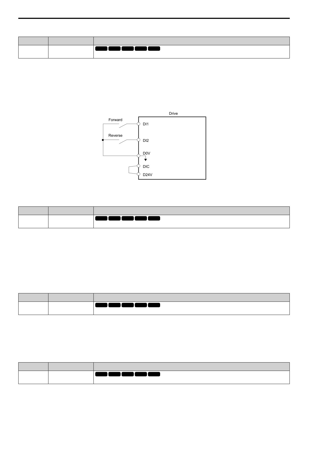
Sets the Forward Run command for 2-wire sequence 1. Set this function and H1-xx = 2 [Reverse Run] at the same time.
ON : Forward Run
OFF : Run Stop
Note:
• Turning ON the Forward Run command terminal and the Reverse Run command terminal will cause alarm EF [FWD/REV Run
Command Input Error] and the motor will ramp to stop.
• Initialize the drive with a 2-wire sequence to set the Forward Run command to terminal DI1.
• This function will not operate at the same time as H1-xx = 3, 4 [Run Command, FWD/REV Cmd].
Figure 12.64 2-Wire Sequence Wiring Example
■ 2: Reverse Run
Setting Value
Function
Description
2
Reverse Run
V/f
OLV OLV/PM AOLV/PM EZOLV
Sets the Forward Run command for 2-wire sequence 1. Set this function and H1-xx = 1 [Forward Run] at the same time.
ON : Reverse Run
OFF : Run Stop
Note:
• Turning ON the Forward Run command terminal and the Reverse Run command terminal will cause alarm EF [FWD/REV Run
Command Input Error] and the motor will ramp to stop.
• Initialize the drive with a 2-wire sequence to set the Reverse Run command to terminal DI2.
• This function will not operate at the same time as H1-xx = 3, 4 [Run Command, FWD/REV Cmd].
■ 3: Run Command
Setting Value
Function
Description
3
Run Command
V/f
OLV OLV/PM AOLV/PM EZOLV
Sets the Run command for 2-wire sequence 2. Set this function and H1-xx = 4 [FWD/REV Cmd] at the same time.
ON : Run
OFF : Stop
Note:
This function will not operate at the same time as H1-xx = 1, 2 [Forward Run, Reverse Run].
■ 4: FWD/REV Cmd
Setting Value
Function
Description
4
FWD/REV Cmd
V/f
OLV OLV/PM AOLV/PM EZOLV
Sets the direction of motor rotation for 2-wire sequence 2. Set this function and H1-xx = 3 [Run Command] together.
ON : Reverse
OFF : Forward
Note:
• You must input the Run command to rotate the motor.
• This function will not operate at the same time as H1-xx = 1, 2 [Forward Run, Reverse Run].
570
12.7 H: TERMINALS
■ 5: 3-Wire Seq.
Setting Value
Function
Description
5
3-Wire Seq.
V/f
OLV OLV/PM AOLV/PM EZOLV
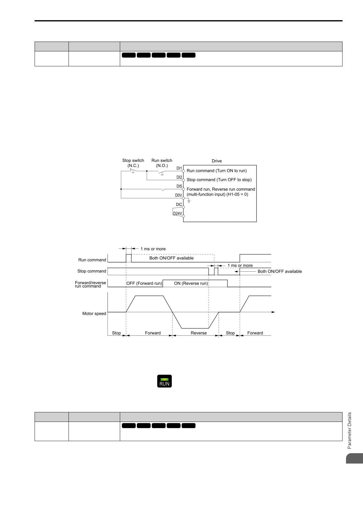
Sets the direction of motor rotation for 3-wire sequence.
If the 3-wire sequence is set to a terminal that is not MFDI terminals DI1 and DI2, these terminals will be the
input terminals for Forward run/Reverse run command. The drive will automatically set terminal DI1 to Run
command (RUN) and terminal DI2 to Stop command (STOP).
When terminal DI1 (Run command) activates for 1 ms minimum, the drive rotates the motor. When terminal DI2
(Stop command) deactivates, the drive stops. When terminal DIx that is set in 3-wire sequence deactivates, the
drive operates in the forward direction, and when it activates, the drive operates in the reverse direction.
WARNING! Sudden Movement Hazard. Set the MFDI parameters before you close control circuit switches. Incorrect Run/Stop
circuit sequence settings can cause serious injury or death from moving equipment.
WARNING! Sudden Movement Hazard. When you use a 3-Wire sequence, set A1-03 = 3330 [Init Parameters = 3-Wire
Initialization] and make sure that b1-17 = 1 [RUN@PowerUp Selection = Disregard RUN] (default). If you do not correctly set
the drive parameters for 3-Wire operation before you energize the drive, the motor can suddenly rotate in reverse when you
energize the drive.
Figure 12.65 3-Wire Sequence Wiring Example
Figure 12.66 3-Wire Sequence Time Chart
Note:
• To input the Run command, activate the terminal for 1 ms minimum.
• The default setting for b1-17 [RUN@PowerUp Selection] is 1 [Disregard RUN]. If you enable the Run command when the drive is
energized, the protective function activates and the
flashes quickly. When the application allows Run, set b1-17 = 2 [Accept
RUN].
■ 6: Jog Reference
Setting Value
Function
Description
6
Jog Reference
V/f
OLV OLV/PM AOLV/PM EZOLV
Sets the drive to use the JOG Frequency Reference (JOG command) set in d1-17. The JOG Frequency Reference (JOG
command) overrides Frequency References 1 to 16 (d1-01 to d1-16).
12
571
12.7 H: TERMINALS
■ 7: Jog Forward
Setting Value
Function
Description
7
Jog Forward
V/f
OLV OLV/PM AOLV/PM EZOLV
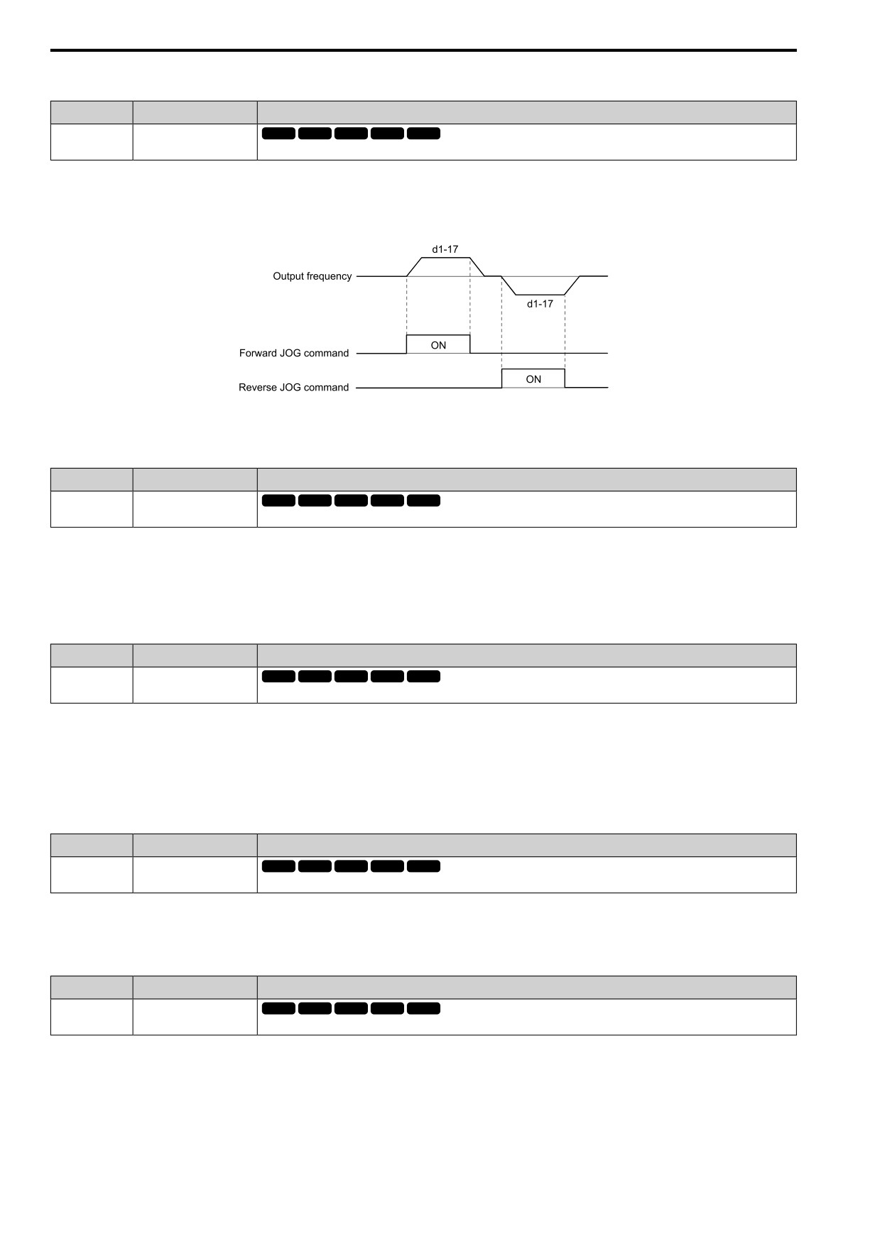
Sets the command to operate the motor in the forward direction at the Jog Frequency set in d1-17 [Jog Reference].
Note:
• It is not necessary to input the Run command.
• The Forward JOG command has priority over all other frequency references.
• When the Forward JOG and Reverse JOG commands are activated at the same time for 500 ms or longer, the drive will ramp to stop.
Figure 12.67 JOG Operation Pattern
■ 8: Jog Reverse
Setting Value
Function
Description
8
Jog Reverse
V/f
OLV OLV/PM AOLV/PM EZOLV
Sets the command to operate the motor in reverse at the Jog Frequency set in d1-17 [Jog Reference].
Note:
• It is not necessary to input the Run command.
• The Reverse JOG command has priority over all other frequency references.
• When the Forward JOG and Reverse JOG commands are activated at the same time for 500 ms or longer, the drive will ramp to stop.
■ 9: Ext Ref 1/2
Setting Value
Function
Description
9
Ext Ref 1/2
V/f
OLV OLV/PM AOLV/PM EZOLV
Sets the drive to use Run command source 1/2 or Reference command source 1/2 when in REMOTE Mode.
Note:
When the drive is receiving a Run command, you cannot switch between reference sources.
ON : b1-15 [Freq. Ref. Sel. 2], b1-16 [Run Comm. Sel 2]
OFF : b1-01 [Freq. Ref. Sel. 1], b1-02 [Run Comm. Sel 1]
■ A: MultSpd Ref1
Setting Value
Function
Description
V/f
OLV OLV/PM AOLV/PM EZOLV
A
MultSpd Ref1
Uses speed references d1-01 to d1-16 to set a multi-step speed reference.
Note:
Refer to “Setting Procedures for Multi-step Speed Operation” in “d: REFERENCE on page 508” for more information.
■ B: MultSpd Ref2
Setting Value
Function
Description
B
MultSpd Ref2
V/f
OLV OLV/PM AOLV/PM EZOLV
Uses speed references d1-01 to d1-16 to set a multi-step speed reference.
Note:
Refer to “Setting Procedures for Multi-step Speed Operation” in “d: REFERENCE on page 508” for more information.
572
12.7 H: TERMINALS
■ C: MultSpd Ref3
Setting Value
Function
Description
C
MultSpd Ref3
V/f
OLV OLV/PM AOLV/PM EZOLV
Uses speed references d1-01 to d1-16 to set a multi-step speed reference.
Note:
Refer to “Setting Procedures for Multi-step Speed Operation” in “d: REFERENCE on page 508” for more information.
■ D: MultSpd Ref4
Setting Value
Function
Description
D
MultSpd Ref4
V/f
OLV OLV/PM AOLV/PM EZOLV
Uses speed references d1-01 to d1-16 to set a multi-step speed reference.
Note:
Refer to "Setting Procedures for Multi-step Speed Operation” in “d: REFERENCE on page 508” for more information.
■ E: Offset Frq 1
Setting Value
Function
Description
E
Offset Frq 1
V/f
OLV OLV/PM AOLV/PM EZOLV
Sets the function to add the offset frequency set in d7-01 [Offset Frq 1] to the frequency reference when the terminal activates.
Note:
Refer to “d7: OFFSET FREQUENCY on page 522” for more information.
■ F: Offset Frq 2
Setting Value
Function
Description
F
Offset Frq 2
V/f
OLV OLV/PM AOLV/PM EZOLV
Sets the function to add the offset frequency set in d7-02 [Offset Frq 2] to the frequency reference when the terminal activates.
Note:
Refer to “d7: OFFSET FREQUENCY on page 522” for more information.
■ 10: Offset Frq 3
Setting Value
Function
Description
V/f
OLV OLV/PM AOLV/PM EZOLV
10
Offset Frq 3
Sets the function to add the offset frequency set in d7-03 [Offset Frq 3] to the frequency reference when the terminal activates.
Note:
Refer to “d7: OFFSET FREQUENCY on page 522” for more information.
■ 11: LOC/REM Sel.
Setting Value
Function
Description
11
LOC/REM Sel.
V/f
OLV OLV/PM AOLV/PM EZOLV
Sets drive control for the keypad (LOCAL) or an external source (REMOTE).
Note:
• When the MFDI terminal sets the LOCAL/REMOTE selection,
on the keypad is disabled.
• When LOCAL Mode is selected, the green light for
comes on.
• When the Run command is ON, you cannot switch between LOCAL Mode and REMOTE Mode.
ON : LOCAL
The keypad is the Frequency reference source and Run command source.
OFF : REMOTE
Parameters b1-01, b1-02 [Freq. Ref. Sel. 1, Run Comm. Sel 1] or b1-15, b1-16 [Freq. Ref. Sel. 2, Run Comm. Sel
2] set the frequency reference and Run command.
12
573
12.7 H: TERMINALS
■ 12: AI Input Sel
Setting Value
Function
Description
12
AI Input Sel
V/f
OLV OLV/PM AOLV/PM EZOLV
Sets the command that enables or disables the terminals selected in H3-14 [An.In Term.Enable Sel].
ON : Terminal selected with H3-14 is enabled
OFF : Terminal selected with H3-14 is disabled
■ 15: FWD/REV Det
Setting Value
Function
Description
V/f
OLV OLV/PM AOLV/PM EZOLV
15
FWD/REV Det
Set the motor rotation direction when you use Simple Closed Loop V/f Control method.
ON : Reverse run
The drive knows that the motor is rotating in the reverse direction.
OFF : Forward run
The drive knows that the motor is rotating in the forward direction.
■ 16: Ref Sample
Setting Value
Function
Description
16
Ref Sample
V/f
OLV OLV/PM AOLV/PM EZOLV
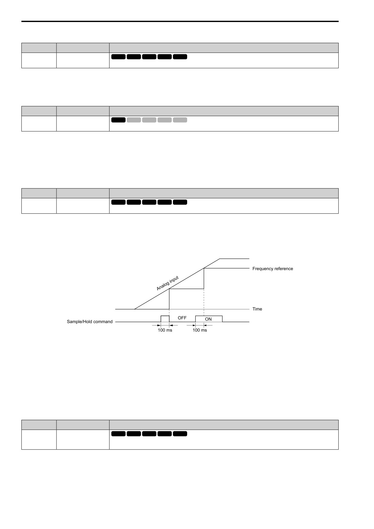
Sets the command to sample the frequency reference at terminal AI1 or AI2, and hold the frequency reference at that frequency.
When the terminal is active for 100 ms, this function reads a sample of the analog frequency reference and holds
that sample. When you input the sample/hold command again, the function again reads a sample of the analog
frequency reference and holds that sample. When you turn off the power, the drive erases the saved analog
frequency and resets the frequency reference to 0.
Figure 12.68 shows an example of how the function operates.
Figure 12.68 Reference Sample Hold
You cannot set the Reference Sample Hold function at the same time as these functions:
• H1-xx = 17 [Ac/Dec Hold]
• H1-xx = 62, 63 [Up Command, Down Command]
• H1-xx = E to 10 [Offset Frq 1 to Offset Frq 3]
• H1-xx = 65, 66 [Up2 Command, Dw2 Command]
If you set them at the same time, the drive will detect oPE03 [Multi-Function Input Setting Err].
■ 17: Ac/Dec Hold
Setting Value
Function
Description
V/f
OLV OLV/PM AOLV/PM EZOLV
17
Ac/Dec Hold
Momentarily pauses motor acceleration and deceleration when the terminal is turned ON, retains the output frequency that was
stored in the drive at the time of the pause, and restarts motor operation.
If the terminal is deactivated, the drive restarts acceleration and deceleration.
When the acceleration/deceleration ramp hold terminal is activated and d4-01 = 1 [FRef Hold Selection =
Enabled], the drive will store the output frequency in memory. While the acceleration/deceleration ramp hold
command is activated, the drive will always restart the motor at this output frequency.
574
12.7 H: TERMINALS
Note:
Refer to “d4: FREQUENCY UP/DOWN on page 516” for more information.
■ 18: Ac/Dec Time1
Setting Value
Function
Description
18
Ac/Dec Time1
V/f
OLV OLV/PM AOLV/PM EZOLV
Sets the drive to use Acceleration/Deceleration Time 1 [C1-01, C1-02] or Acceleration/Deceleration Time 2 [C1-03, C1-04].
Note:
Refer to “C1: ACCEL / DECEL on page 488” for more information.
■ 19: Ac/Dec Time2
Setting Value
Function
Description
19
Ac/Dec Time2
V/f
OLV OLV/PM AOLV/PM EZOLV
Set this function and H1-xx = 18 [Ac/Dec Time1] together. Sets the drive to use Acceleration/Deceleration Time 3 [C1-05, C1-
06] or Acceleration/Deceleration Time 4 [C1-07, C1-08].
Note:
Refer to “C1: ACCEL / DECEL on page 488” for more information.
■ 1A: Drive Enable
Setting Value
Function
Description
1A
Drive Enable
V/f
OLV OLV/PM AOLV/PM EZOLV
Sets the function to show dnE [Drive Enabled] on the keypad and ignore Run commands when the terminal is OFF.
If you input the Run command before you turn ON the Drive Enable terminal, you must input the Run command
again to operate the drive. When the terminal set for Drive Enable is turned OFF when the drive is operating, the
drive will use the stopping method set in b1-03 [Stopping Method Selection] to stop the motor.
ON : Run command is accepted.
OFF : Run command is disabled. When the drive is running, it stops according to b1-03 setting.
■ 1B: Baseblock NO
Setting Value
Function
Description
1B
Baseblock NO
V/f
OLV OLV/PM AOLV/PM EZOLV
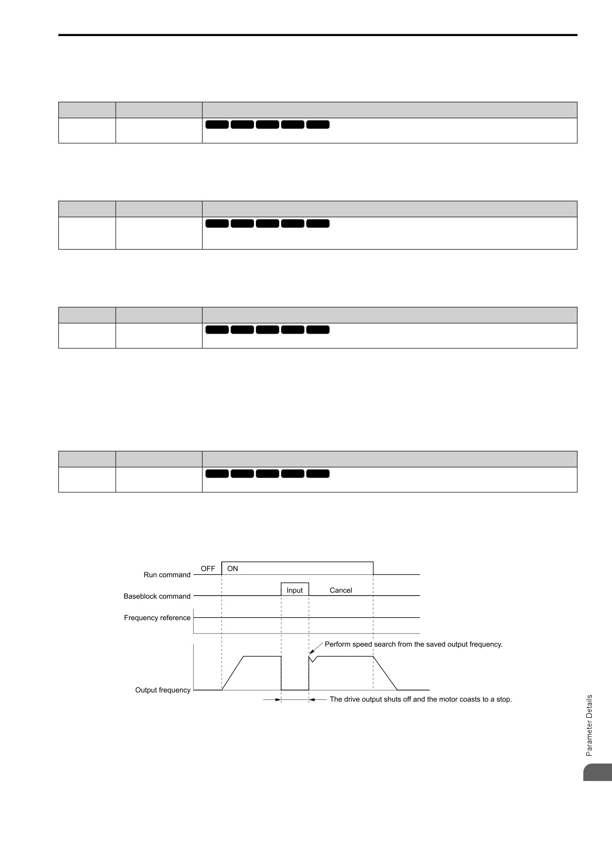
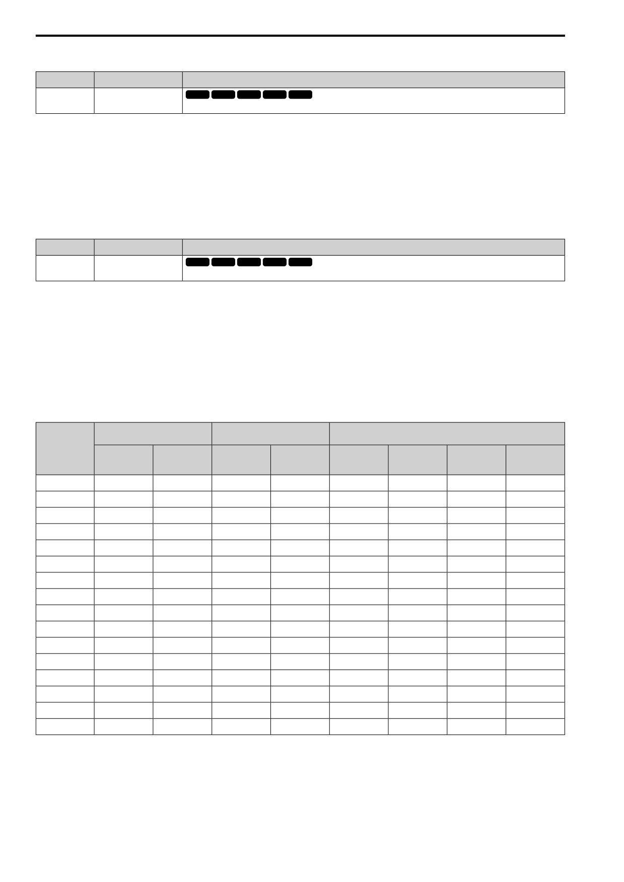
Sets the command that stops drive output and coasts the motor to stop when the input is ON.
The keypad flashes bb [Baseblock]. If you cancel the baseblock command when the Run command is active, the
drive will restart the motor and use the speed search function.
WARNING! Sudden Movement Hazard. When you use a mechanical holding brake with the drive in a lifting application, you
must close the brake if an input terminal triggers the Baseblock command to stop drive output. If you enter the baseblock
command, the motor will suddenly coast and the load will slip, which can cause serious injury or death.
Figure 12.69 Baseblock Command Time Chart
ON : Baseblock (drive output stop)
OFF : Normal operation
12
575
12.7 H: TERMINALS
■ 1E: Baseblock NC
Setting Value
Function
Description
1E
Baseblock NC
V/f
OLV OLV/PM AOLV/PM EZOLV
Sets the command that stops drive output and coasts the motor to stop when the input terminal is OFF.
The keypad flashes bb [Baseblock]. If you cancel the baseblock command when the Run command is active, the
drive will restart the motor and use the speed search function.
ON : Normal operation
OFF : Baseblock (drive output stop)
WARNING! Sudden Movement Hazard. When you use a mechanical holding brake with the drive in a lifting application, you
must close the brake if an input terminal triggers the Baseblock command to stop drive output. If you enter the baseblock
command, the motor will suddenly coast and the load will slip, which can cause serious injury or death.
■ 20 to 2F: External Fault
Setting Value
Function
Description
20 to 2F
External Fault
V/f
OLV OLV/PM AOLV/PM EZOLV
Sets a command to stop the drive when a failure or fault occurs on an external device.
If an external fault is input to the drive, the keypad will show EFx [External Fault (Terminal Dx)], where x is the
number of the terminal (terminal DIx) to which the external fault signal is assigned. For example, when an
external fault signal is input to terminal DI3, the keypad will show EF3.
Use these conditions to select the value to set in H1-xx:
• Signal input method from peripheral devices
• External fault detection method
• Motor stopping method (operation after external fault detection)
Table 12.39 shows the relation between the conditions and the value set to H1-xx.
Table 12.39 Stopping Methods for External Fault
Signal Input Method from
External Fault Detection Method
Peripheral Devices *1
*2
Stopping Method
Setting
Detected
Continuous
Always
Ramp to Stop
Coast to Stop
Fast Stop
N.O.
N.C.
during RUN
Operation
Detected
(Fault)
(Fault)
(Fault)
Only
(Alarm Only)
20
x
-
x
-
x
-
-
-
21
-
x
x
-
x
-
-
-
22
x
-
-
x
x
-
-
-
23
-
x
-
x
x
-
-
-
24
x
-
x
-
-
x
-
-
25
-
x
x
-
-
x
-
-
26
x
-
-
x
-
x
-
-
27
-
x
-
x
-
x
-
-
28
x
-
x
-
-
-
x
-
29
-
x
x
-
-
-
x
-
2A
x
-
-
x
-
-
x
-
2B
-
x
-
x
-
-
x
-
2C
x
-
x
-
-
-
-
x
2D
-
x
x
-
-
-
-
x
2E
x
-
-
x
-
-
-
x
2F
-
x
-
x
-
-
-
x
*1
Set the terminal to N.O. (detects external fault when switched ON) or N.C. (detects external fault when switched OFF).
*2
Set the drive to always detect each fault or to detect only during run.
576
12.7 H: TERMINALS
■ 30: DCInj Cmd
Setting Value
Function
Description
30
DCInj Cmd
V/f
OLV OLV/PM AOLV/PM EZOLV
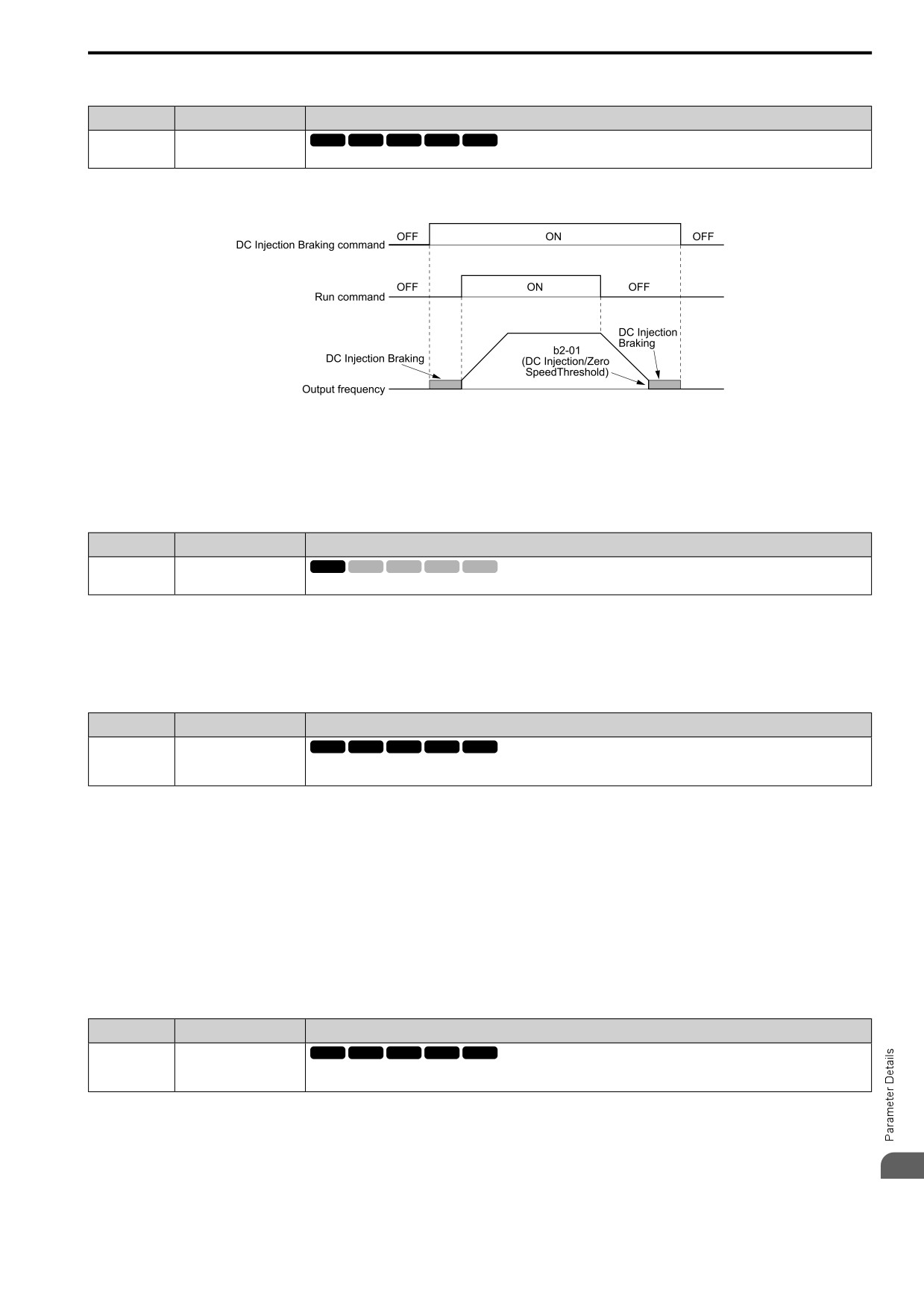
Sets the command to use DC Injection Braking to stop the motor.
If you input the Run command or JOG command, it will cancel DC Injection Braking.
Figure 12.70 shows the time chart of the DC Injection Braking function.
Figure 12.70 DC Injection Braking Time Chart
Note:
• When A1-02 = 8 [Control Method = EZ Vector], this function is available only when you use a PM motor.
• Refer to "b2: DC INJ / SHORT CKT BRAKE on page 454" for more information.
■ 32: HiSlipBraking
Setting Value
Function
Description
V/f
OLV OLV/PM AOLV/PM EZOLV
32
HiSlipBraking
Sets the command to use high-slip braking to stop the motor.
Note:
• When you restart the drive after you use high-slip braking, make sure that the drive fully stops the motor then clear the high-slip
braking input.
• Refer to “n3: HIGHSLIP/OVEREXCITATION BRAKE on page 678” for more information.
■ 34: Fast Stop NO
Setting Value
Function
Description
V/f
OLV OLV/PM AOLV/PM EZOLV
34
Fast Stop NO
Sets the command to ramp to stop in the deceleration time set in C1-09 [Fast Stop Time] when the input terminal is activated
while the drive is operating.
If you cancel the fast stop input, the drive will not restart the motor until you meet these conditions:
• Fully stop the motor
• Cancel the Run command
• Cancel the fast stop command
Note:
• To use the N.C. switch to input the fast stop command, set 35 [Fast Stop NC].
• For details, refer to C1-09: Fast Stop Time on page 491.
• Set C1-09 [Fast Stop Time] to a correct deceleration time. If the deceleration time is too short, it can cause an overvoltage fault and
failure to stop the motor from coasting.
■ 35: Fast Stop NC
Setting Value
Function
Description
35
Fast Stop NC
V/f
OLV OLV/PM AOLV/PM EZOLV
Sets the command to ramp to stop in the deceleration time set in C1-09 [Fast Stop Time] when the input terminal is activated
while the drive is operating.
If you cancel the fast stop input, the drive will not restart the motor until you meet these conditions:
• Fully stop the motor
• Cancel the Run command
12
• Cancel the fast stop command
577
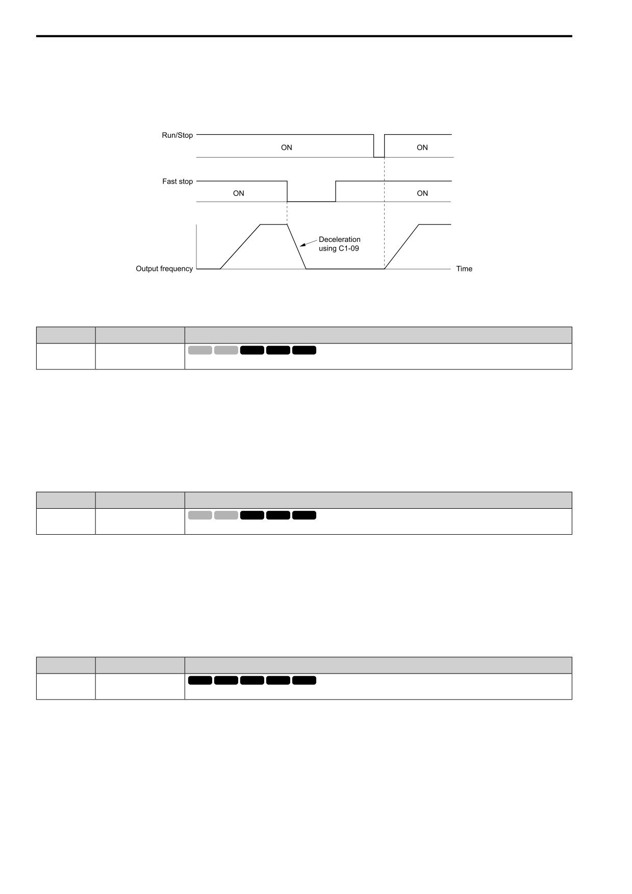
12.7 H: TERMINALS
Note:
• To use the N.O. switch to input the fast stop command, set 34 [Fast Stop NO].
• For details, refer to C1-09: Fast Stop Time on page 491.
• Set C1-09 [Fast Stop Time] to a correct deceleration time. If the deceleration time is too short, it can cause an overvoltage fault and
failure to stop the motor from coasting.
Figure 12.71 shows an example of how fast stop operates.
Figure 12.71 Fast Stop Time Chart
■ 3E: SCBraking NO
Setting Value
Function
Description
3E
SCBraking NO
V/f
OLV OLV/PM AOLV/PM EZOLV
Sets operation of Short Circuit Braking (N.O.).
The drive will short circuit the three phases of a PM motor to cause braking torque in the spinning motor.
Note:
• When A1-02 = 8 [Control Method = EZ Vector], this function is available only when you use a PM motor.
• Refer to "b2: DC INJ / SHORT CKT BRAKE on page 454" for more information.
ON : Short Circuit Braking is enabled.
OFF : Normal operation
■ 3F: SCBraking NC
Setting Value
Function
Description
V/f
OLV OLV/PM AOLV/PM EZOLV
3F
SCBraking NC
Sets operation of Short Circuit Braking (N.C.).
The drive will short circuit the three phases of a PM motor to cause braking torque in the spinning motor.
Note:
• When A1-02 = 8 [Control Method = EZ Vector], this function is available only when you use a PM motor.
• Refer to "b2: DC INJ / SHORT CKT BRAKE on page 454" for more information.
ON : Normal operation
OFF : Short Circuit Braking is enabled.
■ 40: KEB Thru1 NC
Setting Value
Function
Description
40
KEB Thru1 NC
V/f
OLV OLV/PM AOLV/PM EZOLV
Sets operation of the KEB1 function through the KEB Ride-Thru 1 (N.C.).
ON : Normal operation
OFF : Deceleration during momentary power loss
When you enable KEB Ride-Thru 1, set L2-29 [KEB Method]. The drive operates with the selected KEB method.
Note:
• If you set KEB Ride-Thru 1 [H1-xx = 40, 41] and KEB Ride-Thru 2 [H1-xx = 42, 43] at the same time, the drive will detect oPE03
[Multi-Function Input Setting Err].
• Refer to "KEB Ride-Thru Function on page 638" for more information.
578
12.7 H: TERMINALS
■ 41: KEB Thru1 NO
Setting Value
Function
Description
41
KEB Thru1 NO
V/f
OLV OLV/PM AOLV/PM EZOLV
Sets operation of the KEB1 function through the KEB Ride-Thru 1 (N.O.).
ON : Deceleration during momentary power loss
OFF : Normal operation
When you enable KEB Ride-Thru 1, set L2-29 [KEB Method]. The drive operates with the selected KEB method.
Note:
• If you set KEB Ride-Thru 1 [H1-xx = 40, 41] and KEB Ride-Thru 2 [H1-xx = 42, 43] at the same time, the drive will detect oPE03
[Multi-Function Input Setting Err].
• Refer to "KEB Ride-Thru Function on page 638" for more information.
■ 42: KEB Thru2 NC
Setting Value
Function
Description
42
KEB Thru2 NC
V/f
OLV OLV/PM AOLV/PM EZOLV
Sets operation of the KEB2 function through the KEB Ride-Thru 2 (N.C.).
ON : Normal operation
OFF : Deceleration during momentary power loss
When KEB Ride-Thru 2 is input, the drive will use Single Drive KEB Ride-Thru 2 for KEB operation. The L2-29
[KEB Method] setting will not have an effect.
Note:
• If you set KEB Ride-Thru 1 [H1-xx = 40, 41] and KEB Ride-Thru 2 [H1-xx = 42, 43] at the same time, the drive will detect oPE03
[Multi-Function Input Setting Err].
• Refer to "KEB Ride-Thru Function on page 638" for more information.
■ 43: KEB Thru2 NO
Setting Value
Function
Description
V/f
OLV OLV/PM AOLV/PM EZOLV
43
KEB Thru2 NO
Sets operation of the KEB2 function through the KEB Ride-Thru 2 (N.O.).
ON : Deceleration during momentary power loss
OFF : Normal operation
When KEB Ride-Thru 2 is input, the drive will use Single Drive KEB Ride-Thru 2 for KEB operation. The L2-29
[KEB Method] setting will not have an effect.
Note:
• If you set KEB Ride-Thru 1 [H1-xx = 40, 41] and KEB Ride-Thru 2 [H1-xx = 42, 43] at the same time, the drive will detect oPE03
[Multi-Function Input Setting Err].
• Refer to "KEB Ride-Thru Function on page 638" for more information.
■ 44: Field weakening
Setting Value
Function
Description
44
Field weakening
V/f
OLV OLV/PM AOLV/PM EZOLV
Sets the function to send the Field Weakening Level and Field Weakening Frequency Limit commands set in d6-01[Field Weak
Level] and d6-02 [Field Weak FqLimit] when the input terminal is activated.
Note:
Refer to “d6: FIELD WEAKENING / FORCING on page 522” for more information.
■ 45: ASR Gain Switch
Setting Value
Function
Description
45
ASR Gain Switch
V/f
OLV OLV/PM AOLV/PM EZOLV
Sets the function to switch the ASR proportional gain set in C5-01 [ASR PGain 1] and C5-03 [ASR PGain 2].
ON : C5-03
Switches the proportional gain to C5-03 [ASR PGain 2].
12
OFF : C5-01
Switches the proportional gain to C5-01 [ASR PGain 1].
579
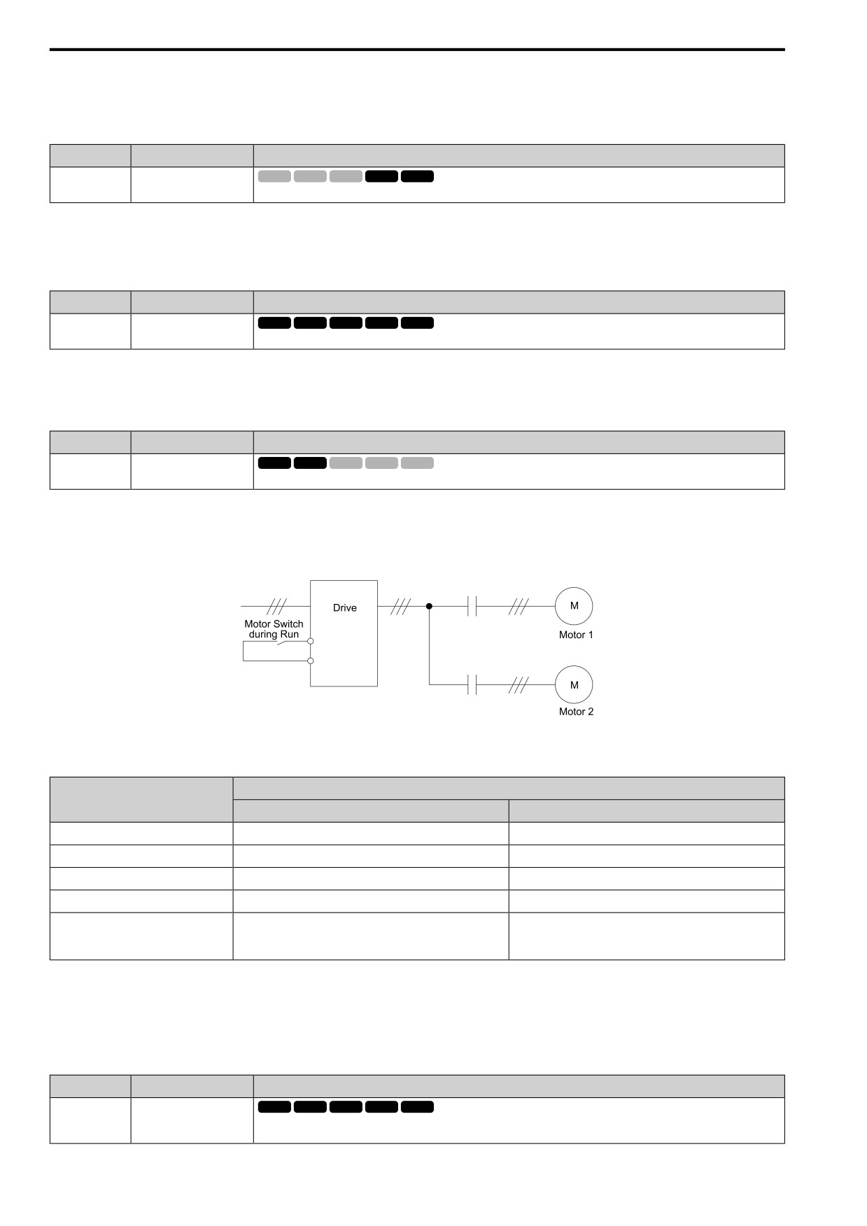
12.7 H: TERMINALS
Note:
Refer to “C5: ASR - SPEED REGULATION on page 499” for more information.
■ 46: ASR I Reset
Setting Value
Function
Description
46
ASR I Reset
V/f
OLV OLV/PM AOLV/PM EZOLV
Sets the command to reset the integral value and use PI control or P control for the speed control loop.
ON : P control
OFF : PI control
■ 60: Timer Fn Input
Setting Value
Function
Description
60
Timer Fn Input
V/f
OLV OLV/PM AOLV/PM EZOLV
Sets the command to start the timer function. Use this setting with Timer Output [H2-xx = 39].
Note:
Refer to “b4: TIMER on page 464” for more information.
■ 61: Motor 2 Select
Setting Value
Function
Description
61
Motor 2 Select
V/f
OLV OLV/PM AOLV/PM EZOLV
Sets the command for the drive to operate motor 1 or motor 2. Stop the motors before switching.
You can use an external input to switch operation between two induction motors. The drive will save the control
methods, V/f patterns, and motor parameters for the two motors.
ON : Operate motor 2
OFF : Operate motor 1
When you select motor 2, the drive will switch to motor 2 parameters.
Table 12.40 Parameters that Switch between Motor 1 and Motor 2
Motor 2 Selection
Parameter
OFF (Motor 1)
ON (Motor 2)
C1: ACCEL / DECEL
C1-01 to C1-04
C1-05 to C1-08
C3: SLIP COMPENSATION
C3-01 to C3-04
C3-21 to C3-24
C4: TORQUE COMPENSATION
C4-01
C4-07
C5: ASR - SPEED REGULATION
C5-01 to C5-08, C5-12
-
E1: V/F PARAMETER MOTOR 1, E2:
E1-xx, E2-xx
E3-xx, E4-xx
MOTOR 1 PARAMETERS, E3: V/F
PARAMETER MOTOR 2, E4: MOTOR 2
PARAMETERS
Note:
• When you use 2 motors, the drive applies the protective function set in L1-01 [Motor Cool Type for OL1 Calc] to motor 1 and motor 2.
• You cannot switch between motors 1 and 2 during run. If you try to switch motors when they are running, it will cause a rUn error.
• You must wait 200 ms minimum to input a Run command.
■ 62: Up Command
Setting Value
Function
Description
62
Up Command
V/f
OLV OLV/PM AOLV/PM EZOLV
Sets the command to use a push button switch to increase the drive frequency reference. You must also set Setting 63 [Down
Command].
580
12.7 H: TERMINALS
ON : Increases the frequency reference.
OFF : Holds the current frequency reference.
Note:
• If you set only the Up command or only the Down command, the drive will detect oPE03 [Multi-Function Input Setting Err].
• If you set two or more of these functions at the same time, the drive will detect oPE03:
-Up/Down command
-Accel/Decel Ramp Hold
-Reference Sample Hold
-Offset Frequency 1, 2, 3 addition
-Up/Down 2 Command
• The Up/Down command does not function in these conditions:
- b1-01 = 2, 3 [Freq. Ref. Sel. 1 = Modbus, Option PCB]
- b1-02 ≠ 1 [Run Comm. Sel 1 ≠ Analog Input]
- Drive is in LOCAL mode
- Set to b1-15 [Freq. Ref. Sel. 2] by use of H1-xx = 9 [MFDI Function Select = Ext Ref 1/2]
When you enter the UP command, the frequency reference increases. When you enter the Down command, the
frequency reference decreases.
The Up and Down commands have priority over all other frequency references. When you enable the Up/Down
command, the drive will ignore these frequency references:
• Frequency reference from Keypad [b1-01 = 0]
• Frequency reference from Analog Input [b1-01 = 1]
• Frequency reference from Pulse Train Input [b1-01 = 4]
Table 12.41 shows the Up and Down commands with their operation.
Table 12.41 Up Command and Down Command
Command status
Drive operation
Up Command (62)
Down Command (63)
OFF
OFF
Keeps the current frequency reference.
ON
OFF
Increases the frequency reference.
OFF
ON
Decreases the frequency reference.
ON
ON
Keeps the current frequency reference.
Combine Frequency Reference Hold Functions and Up/Down Commands
• When you clear the Run command or when d4-01 = 0 [Freq Reference Hold Selection = Disabled], and you
restart the drive, the Up/Down command resets to 0.
• When d4-01 = 1 [Enabled], the drive saves the frequency reference set during the Up/Down command. When
you cycle the Run command or restart the drive, the drive saves the frequency reference value and restarts the
motor at this frequency value. After you clear the Run command, activate the terminal set for the Up command
or Down command to set the saved reference value to 0.
Note:
Refer to “d4-01 [Freq Reference Hold Selection]” for more information.
Combine Upper/Lower Limits of the Frequency Reference and the Up/Down Commands
Set the upper limit value of the frequency reference to d2-01 [Frequency Reference Upper Limit].
Use an analog input or d2-02 [Frequency Reference Lower Limit] to set the lower limit value of the frequency
reference. The configurable values change when the setting for d4-10 [Up/Down Freq Lower Limit Select]
changes. When you input a Run command, these are the lower limits of the frequency reference:
• When the lower limit of the frequency reference is set only for d2-02, the drive accelerates the motor to the
lower limit value of the frequency reference when you input the Run command.
• When the lower limit of the frequency reference is set only for analog input, the drive accelerates the motor to
the lower limit value of the frequency reference when the Run command, and Up command or Down command
for the drive is enabled. When only the Run command is enabled, the motor does not start.
• When these conditions occur, the drive accelerates the motor to the d2-02 setting value when the Run command
is input. When the motor accelerates to the setting value of d2-02, the motor accelerates to the lower limit value
of the analog input when you enable the Up/Down command.
12
- The lower limit value of the frequency reference is set for the analog input and d2-02
- The lower limit value of the analog input is higher than the setting value of d2-02
581
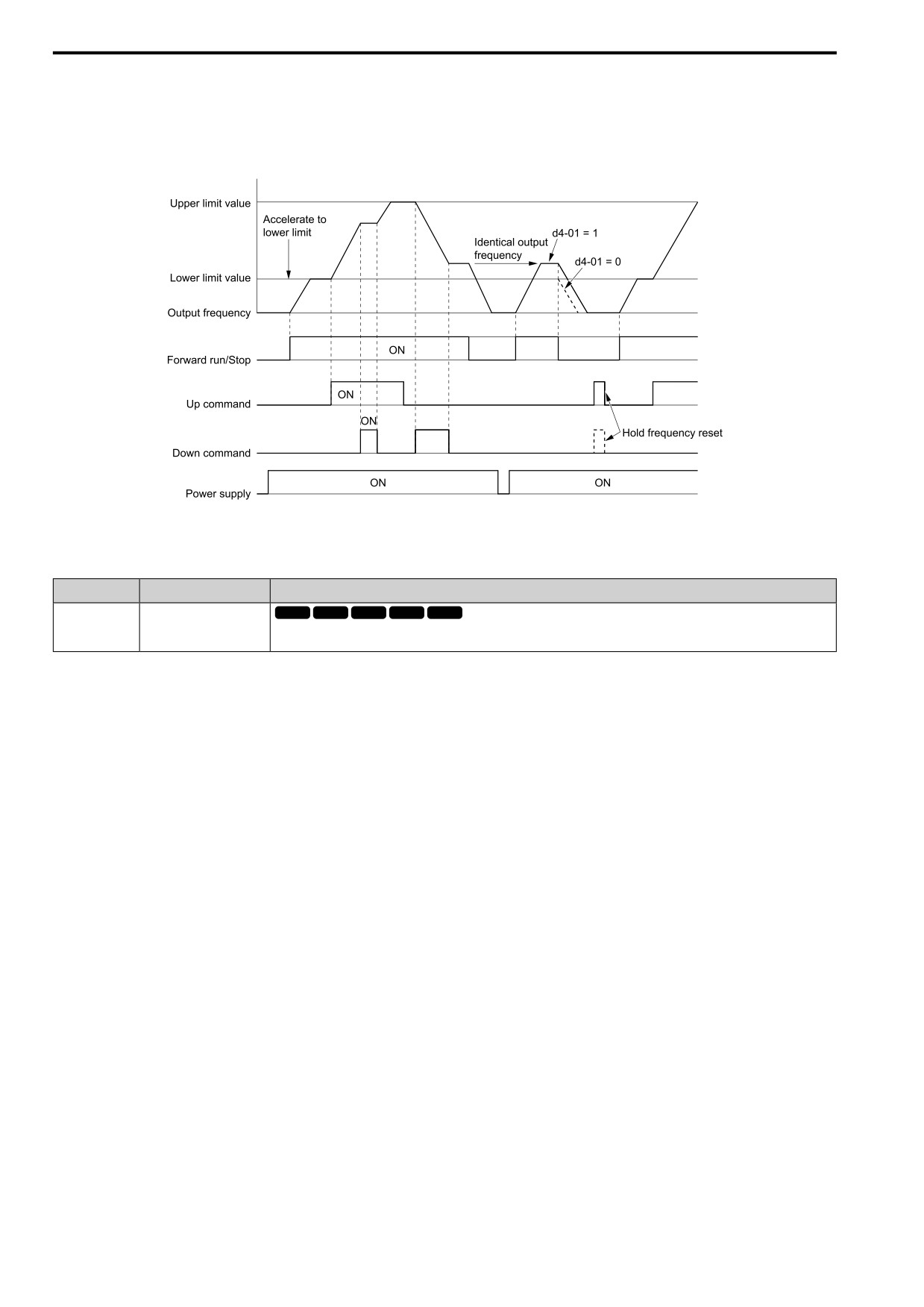
12.7 H: TERMINALS
Note:
Refer to “d4-10: Up/Down Freq Lower Limit Select” for details.
Figure 12.72 shows an example of how Up/Down command operates. In this example, the lower limit value of the
frequency reference is set in d2-02. Figure 12.72 shows the time chart when Freq Reference Retention Select [d4-
01] is enabled and disabled.
Figure 12.72 Up/Down Command Time Chart
■ 63: Down Command
Setting Value
Function
Description
63
Down Command
V/f
OLV OLV/PM AOLV/PM EZOLV
Sets the command to use a push button switch to decrease the drive frequency reference. You must also set Setting 62 [Up
Command].
ON : Decreases the frequency reference.
OFF : Holds the current frequency reference.
Note:
• If you set only the Up command or only the Down command, the drive will detect oPE03 [Multi-Function Input Setting Err].
• If you set two or more of these functions at the same time, the drive will detect oPE03:
-Up/Down command
-Accel/Decel Ramp Hold
-Reference Sample Hold
-Offset Frequency 1, 2, 3 addition
-Up/Down 2 Command
• The Up/Down command does not function in these conditions:
-b1-01 = 2, 3 [Freq. Ref. Sel. 1 = Modbus, Option PCB]
-b1-02 ≠ 1 [Run Comm. Sel 1 ≠ Analog Input]
-Drive is in LOCAL mode
-Set to b1-15 [Freq. Ref. Sel. 2] by use of H1-xx = 9 [MFDI Function Select = Ext Ref 1/2]
When you enter the UP command, the frequency reference increases. When you enter the Down command, the
frequency reference decreases.
The Up and Down commands have priority over all other frequency references. When you enable the Up/Down
command, the drive will ignore these frequency references:
• Frequency reference from Keypad [b1-01 = 0]
• Frequency reference from Analog Input [b1-01 = 1]
• Frequency reference from Pulse Train Input [b1-01 = 4]
582
12.7 H: TERMINALS
■ 65: Up2 Command
Setting Value
Function
Description
65
Up2 Command
V/f
OLV OLV/PM AOLV/PM EZOLV
Sets the function to increase the frequency reference bias value to accelerate the motor when the terminal is activated. Set this
function and H1-xx = 66 [Dw2 Command] together.
When you activate the terminal set for Up2 Command, the bias will increase. When you activate the terminal set
for Down 2 Command, the bias will decrease. When you activate or deactivate the two commands, the drive will
hold the frequency reference. Table 12.42 gives information about the relation between operation of the Up/Down
2 Command and d4-01, d4-03, d4-05.
Note:
• When using this function, set the optimal bias limit value with d4-08 and d4-09 [Up/Dw2 Bias Upper Limit and Up/Dw2 Bias Lower
Limit].
• Refer to "d4: FREQUENCY UP/DOWN on page 516" for more information.
Table 12.42
Up
2 Command, Down 2 Command
Func
Frequency
Storing the Frequency Reference or
d4-03
d4-05
d4-01
Operation
tion
Reference Source
Frequency Bias
1
0
•
When the Up 2 Command is active, the drive
Not stored.
accelerates the motor (increases the bias value).
•
When the Down 2 Command is active, the
When the bias value and frequency reference are
drive decelerates the motor (decreases the bias
constant for 5 seconds after the frequency
value)
reference hold starts, the drive will add the bias
value to the enabled frequency reference, then
•
When the Up 2 Command and Down 2
reset.
Command are not active and when the Up 2
0
Command and Down 2 Command are active,
2
1
the drive holds the output frequency (holds the
bias value).
Multi-step speed
0.00
•
When the frequency changes, it will reset the
reference
bias.
•
For all other statuses, the drive will follow the
frequency reference.
•
When the Up 2 Command is active, the drive
Not stored.
accelerates the motor.
•
When the Down 2 Command is active, the
3
1
-
drive decelerates the motor.
•
For all other statuses, the drive will follow the
frequency reference.
4
0
•
When the Up 2 Command is active, the drive
Not stored.
accelerates the motor to “Frequency Reference
+ d4-03” (the bias value will increase to the
When the bias value and frequency reference are
value set in d4-03)
constant for 5 seconds after the frequency
•
When the Down 2 Command is active, the
reference hold starts, the drive will add the bias
drive decelerates the motor to “Frequency
value to the enabled frequency reference, then
Reference - d4-03” (the bias value will decrease
reset.
to the value set in d4-03).
Multi-step speed
>0
-
•
When the Up 2 Command and Down 2
reference
5
1
Command are not active and when the Up 2
Command and Down 2 Command are active,
the drive holds the output frequency (holds the
bias value).
•
When the frequency changes, it will reset the
bias.
•
For all other statuses, the drive will follow the
frequency reference.
6
0
•
When the Up 2 Command is active, the drive
Not stored.
accelerates the motor (increases the bias value).
•
When the Down 2 Command is active, the
When the bias value is constant for 5 seconds after
drive decelerates the motor (decreases the bias
the frequency reference hold starts, the drive will
value)
store the bias value in d4-06. You cannot rewrite
the frequency reference is not possible. The drive
•
When the Up 2 Command and Down 2
will store only the bias value.
Others
Command are not active and when the Up 2
(Analog input,
0
0
Command and Down 2 Command are active,
7
transmission)
1
the drive holds the output frequency (holds the
bias value).
•
During acceleration or deceleration, when the
frequency reference increases or decreases
more than d4-07, the drive holds the bias value
until the output frequency and the actual
frequency reference agree (speed agreement).
12
583
12.7 H: TERMINALS
Func
Frequency
Storing the Frequency Reference or
d4-03
d4-05
d4-01
Operation
tion
Reference Source
Frequency Bias
• When the Up 2 Command is active, the drive
Not stored.
accelerates the motor (increases the bias value).
• When the Down 2 Command is active, the
8
0
1
-
drive decelerates the motor (decreases the bias
value)
• For all other statuses, the drive will follow the
frequency reference.
9
0
• When the Up 2 Command is active, the drive
Not stored.
Others
accelerates the motor to “Frequency Reference
(Analog input,
+ d4-03” (the bias value will increase to the
When the bias value is constant for 5 seconds after
transmission)
value set in d4-03)
the frequency reference hold starts, the drive will
• When the Down 2 Command is active, the
store the bias value in d4-06. You cannot rewrite
drive decelerates the motor to “Frequency
the frequency reference is not possible. The drive
>0
-
Reference - d4-03” (the bias value will decrease
will store only the bias value.
10
1
to the value set in d4-03).
• During acceleration or deceleration, when the
frequency reference increases or decreases
more than d4-07, the drive holds the bias value
until the output frequency and the actual
frequency reference agree (speed agreement).
■ 66: Dw2 Command
Setting Value
Function
Description
66
Dw2 Command
V/f
OLV OLV/PM AOLV/PM EZOLV
Sets the function to decrease the frequency reference bias value to decelerate the motor when the terminal is activated. Set this
function and H1-xx = 65 [Up2 Command] at the same time.
When you activate the terminal set for Up2 Command, the bias will increase. When you activate the terminal set
for Down 2 Command, the bias will decrease. When you activate or deactivate the two commands, the drive will
hold the frequency reference.
Note:
• When using this function, set the optimal bias limit value with d4-08 and d4-09 [Up/Dw2 Bias Upper Limit and Up/Dw2 Bias Lower
Limit].
• Refer to “d4: FREQUENCY UP/DOWN on page 516” for more information.
■ 67: SpdSrch Fmax
Setting Value
Function
Description
67
SpdSrch Fmax
V/f
OLV OLV/PM AOLV/PM EZOLV
Sets the function to start speed search using an external reference although b3-01 = 0 [SpSrch@Start Selection = Disabled].
When the terminal is turned ON for b3-24 = 2 [SpSrch Method Selection = Current Det2], the drive starts speed
search from the maximum output frequency.
Note:
• The drive will detect oPE03 [Multi-Function Input Setting Err] when H1-xx = 67 and 68 are set at the same time.
• Refer to “b3: SPEED SEARCH on page 456” for more information.
■ 68: SpdSrch Fref
Setting Value
Function
Description
68
SpdSrch Fref
V/f
OLV OLV/PM AOLV/PM EZOLV
Sets the function to start speed search using an external reference although b3-01 = 0 [SpSrch@Start Selection = Disabled].
When the terminal is turned ON for b3-24 = 2 [SpSrch Method Selection = Current Det2], the drive starts speed
search from the frequency reference.
Note:
• The drive will detect oPE03 [Multi-Function Input Setting Err] when H1-xx = 67 and 68 are set at the same time.
• Refer to “b3: SPEED SEARCH on page 456” for more information.
■ 6A: PID Disable
Setting Value
Function
Description
6A
PID Disable
V/f
OLV OLV/PM AOLV/PM EZOLV
Sets the command to disable PID control when b5-01 = 1 [PID Enable = Enabled].
ON : PID control disabled
OFF : PID control enabled
584
12.7
H: TERMINALS
■ 71: PID I Reset
Setting Value
Function
Description
71
PID I Reset
V/f
OLV OLV/PM AOLV/PM EZOLV
Sets the command to reset and hold the PID control integral to 0 when the terminal is ON.
Note:
Refer to “b5: PID CONTROL on page 466” for more information.
■ 72: PID I Hold
Setting Value
Function
Description
72
PID I Hold
V/f
OLV OLV/PM AOLV/PM EZOLV
Sets the command to hold the integral value of the PID control while the terminal is activated.
When you turn off the input terminal, PID control restarts the integral.
Note:
Refer to “b5: PID CONTROL on page 466” for more information.
■ 75: PID SS Cancel
Setting Value
Function
Description
75
PID SS Cancel
V/f
OLV OLV/PM AOLV/PM EZOLV
Sets the PID soft starter function.
ON : No
Disables b5-17 [PID Accel/Decel Time].
OFF : Yes
Enables b5-17 [PID Accel/Decel Time].
Note:
Refer to “b5: PID CONTROL on page 466” for more information.
■ 76: PID InLv Select
Setting Value
Function
Description
76
PID InLv Select
V/f
OLV OLV/PM AOLV/PM EZOLV
Sets the command to turn the terminal ON and OFF to switch the PID input level (polarity).
Note:
Refer to “b5: PID CONTROL on page 466” for more information.
■ 77: PID SP 1
Setting Value
Function
Description
77
PID SP 1
V/f
OLV OLV/PM AOLV/PM EZOLV
Set this function and H1-xx = 78 [PID SP 2] together. Sets the function to switch the PID setpoint to b5-58 to b5-60 [PID
Setpoints 2 to 4].
Refer to “b5-58 to b5-60: PID Setpoints 2 to 4 on page 479” for more information.
■ 78: PID SP 1
Setting Value
Function
Description
V/f
OLV OLV/PM AOLV/PM EZOLV
78
PID SP 1
Set this function and H1-xx = 77 [PID SP 1] at the same time. Sets the function to switch the PID setpoint to b5-58 to b5-60
[PID Setpoints 2 to 4].
Refer to “b5-58 to b5-60: PID Setpoints 2 to 4 on page 479” for more information.
■ 7A: PID BiDir
Setting Value
Function
Description
7A
PID BiDir
V/f
OLV OLV/PM AOLV/PM EZOLV
Sets operation of the PID Bi-Directional function.
12
ON : Enabled
585
12.7 H: TERMINALS
OFF : Disabled
■ 7B: Fault Reset
Setting Value
Function
Description
7B
Fault Reset
V/f
OLV OLV/PM AOLV/PM EZOLV
Sets the command to reset the current fault when the Run command is inactive.
If the drive detects a fault, the drive will activate the fault relay output, turn off the output, and the motor will
coast to stop.
If the drive detects a fault for which you can set the stopping method, apply the appropriate Stopping Method.
Then push
(RESET) on the keypad to turn the Run command OFF, or activate the fault reset terminal to reset
the fault.
Note:
The drive ignores the fault reset command when the Run command is active. Remove the Run command before trying to reset a fault.
■ 7C: Prg Lock
Setting Value
Function
Description
7C
Prg Lock
V/f
OLV OLV/PM AOLV/PM EZOLV
Sets the command to prevent parameter changes when the terminal is OFF.
You can continue to view parameter setting values when the terminal is OFF [Parameters Cannot be Edited].
ON : Program Lockout
OFF : Parameter Write Prohibit
■ 7D: Drive OH2
Setting Value
Function
Description
7D
Drive OH2
V/f
OLV OLV/PM AOLV/PM EZOLV
Sets the drive to display an oH2 [Drive Overheat Warning] alarm when the input terminal is ON. The alarm does not have an
effect on drive operation.
■ 7E: Node Setup
Setting Value
Function
Description
7E
Node Setup
V/f
OLV OLV/PM AOLV/PM EZOLV
Sets the function in CANopen communications to start the Node Setup function to set the drive node address from the host
controller.
■ 7F: Comms Test
Setting Value
Function
Description
V/f
OLV OLV/PM AOLV/PM EZOLV
7F
Comms Test
Set the function for the drive to self-test RS-485 serial communications operation.
The Self-Diagnostics function connects the transmission terminal of the control terminal block to the reception
terminal. The function transmits the data that the drive sent to make sure that the drive can communicate correctly.
Note:
Refer to Modbus communications “Self-Diagnostics” for the self-diagnostics procedure.
■ 90 to 96: Q2pack DI1 to 7
Setting Value
Function
Description
90 - 96
Q2pack DI1 to 7
V/f
OLV OLV/PM AOLV/PM EZOLV
Sets digital inputs used with Q2pack. Refer to the Q2pack online manual for more information.
Note:
You cannot set values 90 to 96 for inverse output.
■ 9F: Q2pack Disable
Setting Value
Function
Description
9F
Q2pack Disable
V/f
OLV OLV/PM AOLV/PM EZOLV
Sets operation of the Q2pack program saved in the drive.
586
12.7 H: TERMINALS
Note:
Set A1-07 = 2 [Q2pack Enable = With DI] to use this function.
ON : Disabled
OFF : Enabled
■ 101 to 19F: Inverse Input of 1 to 9F
Setting Value
Function
Description
101 to 19F
Inverse Input of 1 to 9F
Sets the function of the selected MFDI to operate inversely. To select the function, enter “1xx”, where the “xx” is the function
setting value.
For example, to use the inverse input of 46 [ASR I Reset], set H1-xx = 146.
Note:
You cannot use inverse input for all functions.
◆ H2: DIGITAL OUTPUTS
H2 parameters set the MFDO terminal functions.
■ H2-01 to H2-03 Terminal NO/NC-CM, DO1-O1C, DO2-O2C Function Selection
The drive has four MFDO terminals. Table 12.43 shows the default function settings for the terminals.
Table 12.43 MFDO Terminals Default Function Settings
No.
Name
Default
Function
H2-01
NO,NC,CM FuncSelection
3
Fault
H2-02
DO1-O1C Func Selection
5
@Run
H2-03
DO2-O2C Func Selection
F
SpeedAgree1
Refer to Table 12.44 to set H2-xx [MFDO Function Select].
Table 12.44 MFDO Setting Values
Setting Value
Function
Reference
Setting Value
Function
Reference
0 *1
Not Used
596
1A
@BaseblockNO
603
1
Drive Ready
596
1B
@BaseblockNC
603
2
Drive Enable
596
1C
FreqRefSource
603
3
Fault
596
1D
RunCmdSource
603
4
Alarm
596
1E
Motor2 Select
603
5
@Run
596
1F
Restart Enable
603
6
@Reverse
597
20
FltReset Active
604
7
Zero Speed
597
21
PolePos Detection
604
B
@FreqOutput
597
22
Ext 24V Supply
604
D
LO/RE Status
598
2F
@SpeedSearch
604
E
EDM Safety
598
30
@TorqueLimit
604
F
SpeedAgree1
598
32
TrqDetect1NO
604
10
USpeedAgree1
599
33
TrqDetect1NC
604
11
SpeedAgree2
599
37
TrqDetect2NO
605
12
USpeedAgree2
600
38
TrqDetect2NC
605
13
FreqDetect 1
600
39
Timer Output
605
14
FreqDetect 2
601
3C
Comparator 1
605
15
FreqDetect 3
601
3D
Comparator 2
606
16
FreqDetect 4
602
3E
PID Fbk Low
606
17
@Fast Stop
602
3F
PID Fbk High
606
18
@KEBridethru
602
4A
DC Bus Undervolt
607
12
19
@ShortCBraking
602
4B
FreqRef Loss
607
587
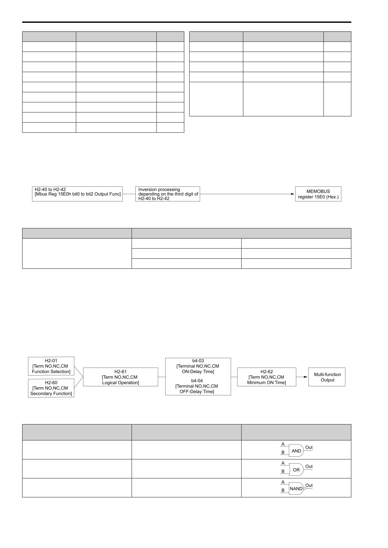
12.7 H: TERMINALS
Setting Value
Function
Reference
Setting Value
Function
Reference
4C
BrkRes Fault
607
67
ModbusReg 1
608
4D
Motor OL1
607
69
ModbusReg 2
608
4E
Drive PreOH
607
6A
DataLog Error
608
4F
PreOHTimeLim
607
90 - 92
Q2pack Digital Output 1 to 3
609
60
BrkTransFault
607
Inverse output of 0 to 92
Sets an inverse output of the function for
61
BrkTransOH
608
the MFDO. Put a 1 at the front of the
100 - 192
609
function setting to set inverse output. For
63
Maintenance
608
example, set 138 for inverse output of 38
[TrqDetect2NC].
65
WattH Pulse
608
66
MechWeakDetect
608
*1
Inverse output is not available.
■ Extend MFDO1 to MFDO3 Function Selection
You can set MFDO functions to bit 0 to bit 2 [Mbus MFDO1 to 3] of Modbus register 15E0 (Hex.). Use H2-40 to
H2-42 [Mbus 15E0h b0 Output Function to Mbus 15E0h b2 Output Function] to select the function.
Figure 12.73 Functional Block Diagram of Modbus Multi-function Output
Table 12.45 Modbus MFDO Registers
Register No. (Hex.)
Name
bit0
Mbus MFDO 1
15E0
bit1
Mbus MFDO 2
bit2
Mbus MFDO 3
Note:
• Refer to H2: DIGITAL OUTPUTS on page 587 for more information about MFDO setting values.
• When you do not set functions to H2-40 to H2-42, set them to 0.
■ Output of Logical Operation Results of MFDO
This enables the logical operation results of two MFDOs to be output to one MFDO terminal.
Use H2-60, H2-63, and H2-66 [NO,NC,CM 2nd Function, DO1 2nd Function, and DO2 2nd Function] to set the
function of the output signal for which you will perform logical operations.
Use H2-61, H2-64, and H2-67 [NO,NC,CM Logic Operation, DO1 Logic Operation, and DO2 Logic Operation]
to set the logical operation.
Figure 12.74 Functional Block Diagram of Logical Operation Output for MFDO 1
Table 12.46 MFDO Logical Operation Table
Logical Operation Selection
Logical Operation Expression
Logical Operation Notation
H2-61, H2-64, H2-67
1
A=B=1
2
A=1 or B=1
3
A=0 or B=0
588