EMERSON PACSystems VersaMax MICRO PLC & NANO PLC. USER MANUAL (2019) - page 34
 

  Index      Manuals     EMERSON PACSystems VersaMax MICRO PLC & NANO PLC. USER MANUAL (2019)


Search            copyright infringement  


Content      ..     32      33      34      35     ..


EMERSON PACSystems VersaMax MICRO PLC & NANO PLC. USER MANUAL (2019) - page 34


User Manual 

Chapter 23 

GFK-1645M 

Dec 2019 


Instruction Set Reference 

498 

23.9.7


Timer and Counter Functions Down Counter 

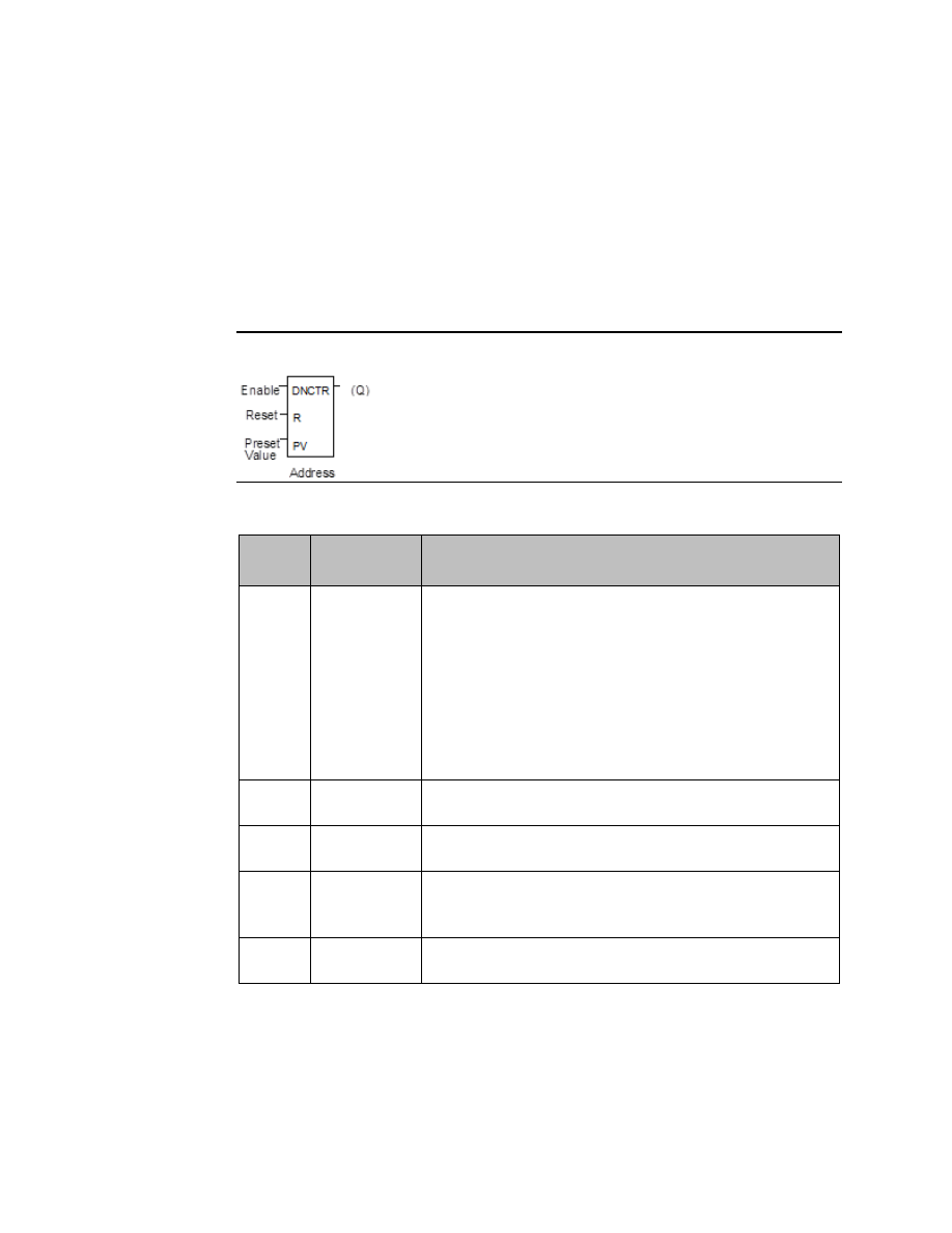
The Down Counter function counts down from a preset value.  The minimum preset value 
is zero; the maximum present value is +32,767 counts.  The minimum current value is 

32,768.  When reset, the current value of the counter is set to the preset value PV.  When 
the enable input transitions from OFF to ON, the current value is decremented by one.  The 
output is ON whenever the current value is less than or equal to zero. 

The  current  value  of  the  Down  Counter  is  retentive  on  power  failure;  no  automatic 
initialization occurs at power-up. 

Figure 344 


Parameters of the Down Counter Function 

Input/ 
Output 

Choices 

Description 

address 

The function uses three consecutive words (registers) of %R memory 
to store the following:  


Current value (CV) = word 1.  


Preset value (PV)   

= word 2.  


Control word 


= word 3.  

Do not use this address with another down counter, up counter, or 
any other instruction or improper operation will result.    
Careful:  Overlapping references will result in erratic counter 
operation. 

enable 

flow 

On a positive transition of enable, the current value is decremented 
by one. 

flow 

When R receives power flow, it resets the current value to the preset 
value. 

PV 

I, Q, M, T, G, R, 
AI, AQ, 
constant, none 

PV is the value to copy into the counter’s preset value when the 

counter is enabled or reset. 

flow, none 

Output Q is energized when the current value is less than or equal to 
zero. 


User Manual 

Chapter 23 

GFK-1645M 

Dec 2019 


Instruction Set Reference 

499 

Example 1 

In  the  example,  the  down  counter  identified  as  COUNTP  counts  500  new  parts  before 
energizing output %Q0005. 

Figure 345 


Example 2 

The  following  example  shows  how  the  PLC  can  keep  track  of  the  number  of  parts  in  a 
temporary  storage  area.  It  uses  an  up/down  counter  pair  with  a  shared  register  for  the 
accumulated or current value. When parts enter the storage area, the up counter increases 
the current value of the parts in storage by 1. When a part leaves the storage area, the down 
counter decrements by 1, decreasing the inventory storage value by 1.  The two counters 
use different register addresses. When a register counts, its current value must be moved 
to the current value register of the other counter. 

Figure 346 


See the pages on Math functions for an example of using the Addition and Subtraction 
functions to provide storage tracking.  


User Manual 

Chapter 24 

GFK-1645M 

Dec 2019 


Service Request Function 

500 

Chapter 24:


Service Request Function 

This chapter explains the Service Request (SVCREQ) function, which requests a special PLC 
service.  It describes SVCREQ parameters for the VersaMax Nano PLC and Micro PLC. 


SVCREQ Function Numbers 


Format of the SVCREQ Function 


SVCREQ 1:  Change/Read Constant Sweep Timer 


SVCREQ 2:  Read Window Times  


SVCREQ 3:  Change Programmer Communications Window Mode  


SVCREQ 4:  Change System Communications Window Mode 


SVCREQ 6:  Change/Read Number of Words to Checksum  


SVCREQ 7:  Read or Change the Time-of-Day Clock  


SVCREQ 8:  Reset Watchdog Timer   


SVCREQ 9:  Read Sweep Time from Beginning of Sweep  


SVCREQ 10:  Read Folder Name    


SVCREQ 11:  Read PLC ID   


SVCREQ 13:  Shut Down (Stop) PLC 


SVCREQ 14:  Clear Fault  


SVCREQ 15:  Read Last-Logged Fault Table Entry   


SVCREQ 16:  Read Elapsed Time Clock   


SVCREQ 18:  Read I/O Override Status 


SVCREQ 23:  Read Master Checksum 


SVCREQ 26/30:  Interrogate I/O 


SVCREQ 34: Enter Analog Calibration Mode 


SVCREQ 35: Execute Analog Calibration  


SVCREQ 52:  Read from Flash 


SVCREQ 53:  Write to Flash 


User Manual 

Chapter 24 

GFK-1645M 

Dec 2019 


Service Request Function 

501 

24.1


SVCREQ Functions 

Each Service Request has its own function number, as listed in the following table. 

Function # 

Description 

Change/Read Constant Sweep Timer  

Read Window Times  

Change Programmer Communications Window Mode and Time 

Change System Communications Window Mode and Time  

reserved 

Change/Read Number of Words to Checksum 

Change/Read Time-of-Day Clock 

Reset Watchdog Timer 

Read Sweep Time from Beginning of Sweep 

10 

Read Folder Name 

11 

Read PLC ID 

12 

reserved 

13 

Shut Down the PLC 

14 

Clear Fault Tables 

15 

Read Last-Logged Fault Table Entry 

16 

Read Elapsed Time Clock 

17 

reserved 

18 

Read I/O Override Status 

19-22 

reserved 

23 

Read Master Checksum 

26, 30 

Interrogate I/O 

27, 28 

reserved 

29 

Read Elapsed Power Down Time 

31-33 

reserved 

34 

Enter Analog Calibration mode 

35 

Execute Analog Calibration 

36-51 

reserved 

52 

Read from Flash 

53 

Write to Flash 

53-255 

reserved 


User Manual 

Chapter 24 

GFK-1645M 

Dec 2019 


Service Request Function 

502 

24.2


Format of the SVCREQ Function 

The SVCREQ function has three inputs and one output. 

Figure 347 


When  the  SVCREQ  receives  power  flow,  the  PLC  is  requested  to  perform  the  function 
number (FNC) indicated. Parameters for the function are located beginning at the reference 
given for PARM. 

This is the beginning of the “parameter block" for the function. The number 

of 16-bit references required depends on the SVCREQ function being used. 

Parameter blocks may be used as both inputs for the function and the location where data 
may  be  output  after  the  function  executes.  Therefore,  data  returned  by  the  function  is 
accessed at the same location specified for PARM. 

The  SVCREQ  function  passes  power  flow  unless  an  incorrect  function  number,  incorrect 
parameters,  or  out-of-range  references  are  specified.    Specific  SVCREQ  functions  have 
additional causes for failure.  

24.2.1


Parameters of the SVCREQ Function 

Input/ 
Output 

Choices 

Description 

enable 

flow 

When enable is energized, the service request is performed. 

FNC 

I, Q M, T, G, R, AI, AQ, 
constant 

Contains the constant or reference for the requested service. 

PARM 

I, Q M, T, G, R, AI, AQ 

Contains the beginning reference for the parameter block for 
the requested service. 

ok 

flow, none 

OK is energized when the function is performed without error. 

Example of the SVCREQ Function 

In the example, when the enabling input %I0001 is ON, SVCREQ function number 7 is called, 
with the parameter block located starting at %R0001.  Output coil %Q0001 is set ON if the 
operation succeeds. 

Figure 348 


User Manual 

Chapter 24 

GFK-1645M 

Dec 2019 


Service Request Function 

503 

24.3


SVCREQ 1:  Change/Read Constant Sweep 
Timer 

Use SVCREQ 1 to enable or disable Constant Sweep Time mode, change the length of the 
Constant Sweep Time, read whether Constant Sweep Time is currently enabled, or read the 
Constant Sweep Time length.  

24.3.1


Input Parameter Block for SCVREQ 1 

For this function, the parameter block has a length of two words. 

24.3.2


Disable Constant Sweep Mode 

To disable Constant Sweep mode, enter SVCREQ function #1 with this parameter block: 

address  

address + 1  

ignored 

24.3.3


Enable Constant Sweep Mode 

To enable Constant Sweep mode, enter SVCREQ function #1 with this parameter block:  

address  

address + 1  

0 or timer value 

Note: 

If the timer should use a new value, enter it in the second word.  If the timer value should not be 
changed, enter 0 in the second word.  If the timer value does not already exist, entering 0 causes 
the function to set the OK output to OFF. 

24.3.4


Change the Constant Sweep Time 

To  change  the  timer  value  without  changing  the  selection  for  sweep  mode  state,  enter 
SVCREQ function #1 with this parameter block:  

address  

address + 1  

new timer value 

24.3.5


Read the Constant Sweep State and Time 

To read the current timer state and value without changing either, enter SVCREQ function 
#1 with this parameter block:  

address  

address + 1  

ignored 


User Manual 

Chapter 24 

GFK-1645M 

Dec 2019 


Service Request Function 

504 

Successful execution will occur, unless:  

1.


A number other than 0, 1, 2, or 3 is entered as the requested operation:  

2.


The sweep time value is greater than 500ms (0.5 seconds).  

3.


Constant  sweep  time  is  enabled  with  no  timer value  programmed  or  with  an  old 
value of 0 for the timer.  

After  the  function  executes,  the  function  returns  the  timer  state  and  value  in  the  same 
parameter block references:  


0 = disabled  

address  

1 = enabled 

address + 1  

current timer value 

Example of SVCREQ 1 

In this example, if contact OV_SWP is set, the Constant Sweep Timer is read, the timer is 
increased  by  two  milliseconds,  and  the  new  timer  value  is  provided  to  the  CPU.    The 
parameter  block  is  in  local  memory  at  location  %R0050.    Because  the  MOVE  and  ADD 
functions  require  three  horizontal  contact  positions,  the  example  logic  uses  discrete 
internal coil %M00001 as a temporary location to hold the successful result of the first rung 
line.  On any sweep in which OV_SWP is not set, %M00001 is turned off. 

Figure 349 


User Manual 

Chapter 24 

GFK-1645M 

Dec 2019 


Service Request Function 

505 

24.4


SVCREQ 2: Read Window Times 

SVCREQ 2 can be used to read the times of the programmer communications window and 
the  system  communications  window.  These  windows  can  operate  in  Limited  or  Run  to 
Completion Mode. 

Mode Name 

Value 

Description  

Limited Mode 

The execution time of the window is limited to 6ms. The window 
terminates when it has no more tasks to complete or after 6ms 
elapses.  

Run  to  Completion 
Mode 

Regardless of the time assigned to a window, it runs until all tasks 
within that window are completed (up to 400ms).  

A window is disabled when the time value is zero.  

24.4.1


Output Parameter Block for SVCREQ 2 

The parameter block has a length of three words:  


High Byte 

Low Byte  


address  

Mode 

Value in ms 

Programmer Window 

address + 1  

Mode 

Value in ms 

System Communications Window 

address + 2  

must be zero 

must be zero 

reserved 

All parameters are output parameters. It is not necessary to enter values in the parameter 
block to program this function. 

Example of SVCREQ 2 

In the following example, when enabling output %Q00102 is set, the Micro PLC CPU places 
the current time values of the windows in the parameter block starting at location %R0010. 

Figure 350 


User Manual 

Chapter 24 

GFK-1645M 

Dec 2019 


Service Request Function 

506 

24.5


SVCREQ 3: Change Programmer 
Communications Window Mode 

Use SVCREQ 3 to change the programmer communications window mode (Limited or Run-
to-Completion).  The change occurs during the next CPU sweep after the function is called. 
The time of the window cannot be changed; it is always 6ms. 

SVCREQ 3 passes power flow to the right unless a mode other than 0 (Limited) or 2 (Run-to-
Completion) is selected. 

The parameter block has a length of one word. 

24.5.1


Changing  the  Programmer  Communications  Window 
Mode 

To change the programmer window, enter SVCREQ 3 with this parameter block:  


High Byte 

Low Byte  

address  

Mode 

Example of SVCREQ 3 

In  the  following  example,  when  enabling  input  %I006  goes  ON,  the  programmer 
communications window is enabled and assigned a value of 6ms. The parameter block is in 
reference memory location %R0051. 

Figure 351 


24.6


SVCREQ  4:  Change  System  Communications 
Window Mode 

Use SVCREQ 4 to change the system communications window mode (Limited or Run-to-
Completion).  The change occurs during the next CPU sweep after the function is called. The 
time of the window cannot be changed; it is always 6ms. 

SVCREQ 4 passes power flow to the right unless a mode other than 0 (Limited) or 2 (Run-to-
Completion) is selected. 

The parameter block has a length of one word. 


User Manual 

Chapter 24 

GFK-1645M 

Dec 2019 


Service Request Function 

507 

24.6.1


Changing the System Communications Window Mode 

To change the programmer window, enter SVCREQ 4 with this parameter block:  


High Byte 

Low Byte  

address  

Mode 

Example of SVCREQ 4  

In the following example, when enabling input %I0003 is ON the system communications 
window is changed to Run-to-Completion mode. The parameter block is at location 
%R0025. 

Figure 352 


24.7


SVCREQ 6: Change/Read Number of Words to 
Checksum 

Use SVCREQ 6 to read or change the number of words in the program to be checksummed. 
The function is successful unless some number other than 0 or 1 is entered as the requested 
operation.  

24.7.1


Parameter Block Formats for SVCREQ 6 

The parameter block has a length of 2 words. To read the word count, the first word of the 
parameter block must contain a zero:  

address 

0 (read word count) 

address + 1 

ignored 

The function returns the current word count in the second word of the parameter block.   

address 

0  

address + 1 

current word count 

To change the word count, the first word of the parameter block must contain a one:  

address 

1 (change word count) 

address + 1 

new word count (0 to 32) 

The PLC will change the number of words to be checksummed to the new value. 


User Manual 

Chapter 24 

GFK-1645M 

Dec 2019 


Service Request Function 

508 

Example of SVCREQ 6 

In  the  example,  when  enabling  contact  FST_SCN  is  set,  the  parameter  blocks  for  the 
checksum function are built.  Later in the program, if input %I0137 turns on, the SVCREQ 
reads the number of words being checksummed. The parameter block for the Read function 
is located at %R0150-151.  The ADD function adds 32 to the current word count in %R0151 
and places the result in %R0153. The parameter block for the Change function is located at 
%R00152-153.  The  second  SVCREQ  then  changes  to  the  new  word  count  specified  in 
%R0153. 

Figure 353 


24.8


SVCREQ 7: Read or Change the Time-of-Day 
Clock 

Use SVCREQ 7 to read or change the time of day clock in the PLC. The data can be either BCD 
or  ASCII.  Either  2-digit-year  or  4-digit-year  format  is  available.  The  function  is  successful 
unless  some  number  other  than  0  (read)  or  1  (change)  is  entered  for  the  requested 
operation, or an invalid data format is specified, or data is provided in an unexpected format. 

24.8.1


Parameter Block Format for SVCREQ 7 

For the date/time functions, the length of the parameter block depends on the data format.  
The data block is either BCD or ASCII. BCD format requires 6 words; packed ASCII requires 
12 words (13 words for 4-digit year). For both data types: 

Hours are stored in 24-hour format.  

Day of the week is a numeric value from 1 (Sunday) to 7 (Saturday). 


2-Digit Year Format 

4-Digit Year Format 

address 

0 = read time and date 
1 = set time and date 

0 = read time and date 
1 = set time and date 

address + 1 

1 = BCD format 
3 = packed ASCII format 

81h = BCD format 
83h = packed ASCII format 

address + 2 to end 

data 

data 

User Manual 

Chapter 24 

GFK-1645M 

Dec 2019 


Service Request Function 

509 

Words 3 to the end of the parameter block contain output data returned by a read function, 
or new data being supplied by a change function.  In both cases, format of these data words 
is  the  same.    When  reading  the  date  and  time,  words  (address  +  2)  to  the  end  of  the 
parameter block are ignored on input.  

24.9


SVCREQ 7 Parameter Block Content: BCD 
Format 

In BCD format, each time and date item occupy one byte, so the parameter block has six 
words. 

24.9.1


2-Digit Year 

The last byte of the sixth  word is not used. When  setting the  date  and  time, this  byte is 
ignored; when reading date and time, the function returns 00. 

Parameter Block Format: 
High Byte:  

Low Byte 


Example: 
Read Date and Time in BCD format 
(Sun., July 3, 1998, at 2:45:30 p.m.) 

1 = change or 
0 = read  

address 

0 (read) 

1 (BCD format) 

address + 1 

1 (BCD format) 

month 

year 

address + 2 

07 (July) 

98 (year) 

hours 

day of month 

address + 3 

14 (hours) 

03 (day) 

seconds 

minutes 

address + 4 

30 (seconds) 

45 (minutes) 

(null) 

day of week 

address + 5 

00 

06 (Friday) 

24.9.2


4-Digit Year 

The parameter block has six words. All bytes are used.  

Parameter Block Format: 
High Byte:  

Low Byte 


Example: 
Read Date and Time in BCD format 
(Sun., July 3, 1998, at 2:45:30 p.m.) 

1 = change or 
0 = read 

address 

00 

00 (read) 

81h (BCD format, 4-digit) 

address + 1 

00 

81h (BCD, 4-digit) 

year 

year 

address + 2 

19 (year) 

98 (year) 

day of month 

month 

address + 3 

03 (day) 

07 (July) 

minutes 

hours 

address + 4 

45 (minutes) 

14 (hours) 

day of week 

seconds 

address + 5 

06 (Friday) 

30 (seconds) 


User Manual 

Chapter 24 

GFK-1645M 

Dec 2019 


Service Request Function 

510 

24.10


SVCREQ 7 Parameter Block Content: Packed 
ASCII Format 

In Packed ASCII format, each digit of the time and date items is an ASCII formatted byte.  
Spaces and colons are embedded into the data to format it for printing or display. ASCII 
format requires 12 words in the parameter block (13 words for 4-digit year).  

24.10.1


2-Digit Year 

Parameter Block Format:  
High Byte 

Low Byte 


Example: 
Read Date and Time in Packed ASCII 
Format (Mon, Oct. 5, 1998 at 
11:13:00pm) 

1 = change or 
0 = read 

address 

0 (read) 

3 (ASCII format) 

address + 1 

3 (ASCII format) 

year 

year 

address + 2 

38 (8) 

39 (9) 

month 

(space) 

address + 3 

31 (1) 

20 (space) 

(space) 

month 

address + 4 

20 (space) 

30 (0) 

day of month 

day of month 

address + 5 

35 (5) 

30 (leading 0) 

hours 

(space) 

address + 6 

31 (1) 

20 (space) 

hours 

address + 7 

3A ( : ) 

31 (1) 

minutes 

minutes 

address + 8 

33 (3) 

31 (1) 

seconds 

address + 9 

30 (0) 

3A ( : ) 

(space) 

seconds 

address + 10 

20 (space) 

30 (0) 

day of week 

day of week 

address + 11 

32 (2: Mon.) 

30 (leading 0) 


User Manual 

Chapter 24 

GFK-1645M 

Dec 2019 


Service Request Function 

511 

24.10.2


4-Digit Year 

Parameter Block Format:  
High Byte 

Low Byte 


Example: 
Read Date and Time in Packed 
ASCII Format (Mon, Oct. 5, 
1998 at 11:13:00pm) 

1 = change or 
0 = read 

address 

0 (read) 

83h (ASCII 4 digit) 

address + 1 

83h (ASCII 4 digit) 

year (hundreds) 

year (thousands) 

address + 2 

39 (9) 

31 (1) 

year (ones) 

year (tens) 

address + 3 

38  (8) 

39 (9) 

month (tens) 

(space) 

address + 4 

31 (1) 

20 (space) 

(space) 

month (ones) 

address + 5 

20 (space) 

30 (0) 

day of month (ones)  day of month (tens)  address + 6 

35 (5) 

30 (leading 0) 

hours (tens) 

(space) 

address + 7 

31 (1) 

20 (space) 

: (colon) 

hours (ones) 

address + 8 

3A ( : ) 

31 (1) 

minutes (ones) 

minutes (tens) 

address + 9 

33 (3) 

31 (1) 

seconds (tens) 

: (colon) 

address + 10 

30 (0) 

3A ( : ) 

(space) 

seconds (ones) 

address + 11 

20 (space) 

30 (0) 

day of week (ones) 

day of week (tens) 

address + 12 

32 (2: Mon.) 

30 (leading 0) 

Example of SVCREQ 7 

In the example, when called for by previous logic, a parameter  block for the time-of-day 
clock is built. It requests the current date and time, then sets the clock to 12 noon using BCD 
format.  The parameter block is located at location %R0300.  Array NOON has been set up 
elsewhere in the program to contain the values 12, 0, and 0.  (Array NOON must also contain 
the  data  at  %R0300.)    BCD  format  requires  six  contiguous  memory  locations  for  the 
parameter block. 


User Manual 

Chapter 24 

GFK-1645M 

Dec 2019 


Service Request Function 

512 

Figure 354 


24.11


SVCREQ 8: Reset Watchdog Timer 

Use  SVCREQ  8  to  reset  the  watchdog  timer  during  the  sweep.    Ordinarily,  when  the 
watchdog timer expires the PLC shuts down without warning.  SVCREQ 8 allows the timer 
to keep going during a time-consuming task (for example, while waiting for a response from 
a communications line).  

CAUTION 

Be sure that resetting the watchdog timer does not adversely affect the controlled process. 

24.11.1


Parameter Block Format for SVCREQ 8 

This function has no associated parameter block.  

Example of SVCREQ 8 

In this example, power flow through enabling output %Q0027 or input %I1476 or internal 
coil %M00010 causes the watchdog timer to be reset.  

Figure 355 


User Manual 

Chapter 24 

GFK-1645M 

Dec 2019 


Service Request Function 

513 

24.12


SVCREQ 9: Read Sweep Time from Beginning 
of Sweep 

Use SVCREQ 9 to read the time in milliseconds since the start of the sweep.  The data format 
is unsigned 16-bit integer.  

24.12.1


Output Parameter Block Format for SVCREQ 9 

The parameter block is an output parameter block only; it has a length of one word.  

address  

time since start of sweep 

Example of SVCREQ 9 

In the following example, the elapsed time from the start of the sweep is always read into 
location %R0200.  If it is greater than 100ms, internal coil %M0200 is turned on. 

Figure 356 


Content      ..     32      33      34      35     ..