EMERSON PACSystems VersaMax MICRO PLC & NANO PLC. USER MANUAL (2019) - page 33
 

  Index      Manuals     EMERSON PACSystems VersaMax MICRO PLC & NANO PLC. USER MANUAL (2019)


Search            copyright infringement  


Content      ..     31      32      33      34     ..


EMERSON PACSystems VersaMax MICRO PLC & NANO PLC. USER MANUAL (2019) - page 33


User Manual 

Chapter 23 

GFK-1645M 

Dec 2019 


Instruction Set Reference 

482 

Example 

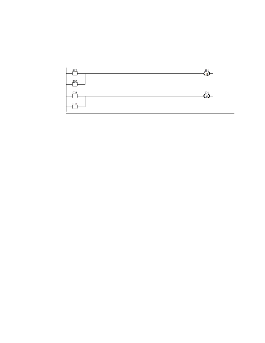
In the example, the coil represented by E1 is turned ON whenever reference E2 or E6 is ON.  
The coil represented by E1 is turned OFF whenever reference E5 or E3 is ON. 

Figure 322 


Retentive SET Coil 

Retentive SET and RESET coils are similar to SET and RESET coils, but they are retained across 
power failure or when the PLC transitions from to Run mode.  A retentive SET coil sets a 
discrete reference ON if the coil receives power flow.  The reference remains ON until reset 
by a retentive RESET coil.  

Retentive SET coils write an undefined result to the transition bit for the given reference. 

Retentive RESET Coil 

This coil sets a discrete reference OFF if it receives power flow.  The reference remains OFF 
until set by a retentive SET coil.  The state of this coil is retained across power failure or when 
the PLC transitions from Stop to Run mode. 

Retentive RESET coils write an undefined result to the transition bit for the given reference. 


User Manual 

Chapter 23 

GFK-1645M 

Dec 2019 


Instruction Set Reference 

483 

23.8


Table Functions 

The Table functions are used to:  


Copy array data: ARRAY MOVE 


Search for values in an array 

The maximum length allowed for these functions is 32,767 for any type.  


Data Types for the Table Functions 

Table functions operate on these types of data:  

INT 

Signed integer 

DINT 

Double precision signed integer 

BIT

16


Bit data type 

BYTE 

Byte data type 

WORD 

Word data type 

23.8.1


Table Functions Array Move 

The Array Move function copies a specified number of elements from a source array to a 
destination array. When the function receives power flow, it copies the number of elements 
specified from the input array, starting at the indexed location. The function then writes the 
copied elements to the output array starting with the indexed location. 

For bit data, when word-oriented memory is selected for the parameters of the source array 
and/or destination array starting address, the least significant bit of the specified word is the 
first bit of the array. 

The indices in an Array Move instruction are 1-based.  In using an Array Move, no element 
outside either the source or destination arrays (as specified by their starting address and 
length) may be referenced. 

The OK output receives power flow unless one of the following occurs:  


Enable is OFF.  


(N + SNX 

 1) is greater than (length).  


(N + DNX 

 1) is greater than (length). 

Figure 323 


16

 Applies to Array Move only. 

User Manual 

Chapter 23 

GFK-1645M 

Dec 2019 


Instruction Set Reference 

484 

Parameters for the Array Move Function 

Input/ 
Output 

Choices 

Description 

enable 

flow 

When the function is enabled, the operation is 
performed. 

SR 

For all: R, AI, AQ 
For INT, BIT, BYTE, WORD: I, Q, 
M, T, G,  
For BIT, BYTE, WORD: SA, SB, SC 

SR contains the starting address of the source array.  
For ARRAY_MOVE_ BIT, any reference may be used; 
it does not need to be byte aligned.   

SNX 

I, Q, M, T, G, R, AI, AQ, constant 

SNX contains the index of the source array. 

DNX 

I, Q, M, T, G, R, AI, AQ, constant 

DNX contains the index of the destination array. 

I, Q, M, T, G, R, AI, AQ, constant 

N provides a count indicator. 

ok 

flow, none 

OK is energized whenever enable is energized. 

DS 

For all: SA, SB, SC, R, AI, AQ 
For INT, BIT, BYTE, WORD: I, Q, 
M, T, G 

The starting address of the destination array.  For 
ARRAY_MOVE_ BIT, any reference may be used; it 
does not need to be byte aligned.  

length 


The number of elements starting at SR and DS that 
make up each array. It is defined as the length of 
SR+DS. 

Example 1:  

In this example, if %R100=3 then %R0003 - %R0007 of the array %R0001 - %R0016 is read 
and is written into %R0104 - %R0108 of the array %R0100 - %R0115.  (%R001 and %R0100 
are declared as type WORD of length 16.) 

Figure 324 


User Manual 

Chapter 23 

GFK-1645M 

Dec 2019 


Instruction Set Reference 

485 

Example 2:  

Using bit memory for SR and DS, %M0011 - %M0017 of the array %M0009 - %M0024 is read 
and then written to %Q0026 - %Q0032 of the array %Q0022 - %Q0037. (%M009 and %Q0022 
are declared as type BOOL of length 16). 

Figure 325 


Example 3:  

Using word memory, for SR and DS, the third least significant bit of %R0001 through the 
second least significant bit of %R0002 of the array containing all 16 bits of %R0001 and four 
bits of %R0002 is read and then written into the fifth least significant bit of %R0100 through 
the fourth least significant bit of %R0101 of the array containing all 16 bits of %R0100 and 
four bits of %R0101. 0001 and %R0100 are declared as type BOOL of length 20). 

Figure 326 


User Manual 

Chapter 23 

GFK-1645M 

Dec 2019 


Instruction Set Reference 

486 

23.8.2


Table Functions Search for Array Values 

Use the Search functions listed below to search for values in an array. 


Search Equal 


Equal to a specified value. 


Search Not Equal 


Not equal to a specified value. 


Search Greater Than 


Greater than a specified value. 


Search Greater Than or Equal 


Greater than or equal to a specified value. 


Search Less Than 


Less than a specified value. 


Search Less Than or Equal 


Less than or equal to a specified value. 

When the Search function receives power, it searches the specified array. Searching begins 
at the starting address (AR) plus the index value (NX). 

Figure 327 


The search continues until the array element of the search object (IN) is found or until the 
end of the array is reached.  If an array element is found, the Found Indication (FD) is set ON 
and the Output Index (output NX) is set to the relative position of this element within the 
array.    If  no  array  element  is  found  before  the  end  of  the  array  is  reached,  the  Found 
Indication (FD) is set OFF and the Output Index (output NX) is set to zero. 

The valid values for input NX are 0 to (length 1). NX should be set to zero to begin searching 
at the first element.  This value increments by one at the time of execution.  The values of 
output NX are 1 to (length).  If the value of input NX is out-of-range, (i.e. < 0 or > length), its 
value is set to the default value of zero. 


User Manual 

Chapter 23 

GFK-1645M 

Dec 2019 


Instruction Set Reference 

487 

Parameters of the Search Functions 

Input/ 
Output 

Choices 

Description 

enable 

flow 

When the function is enabled, the search is performed. 

AR 

For all: R, AI, AQ 
For INT, BYTE, WORD: I, Q, 
M, T, G  
For BYTE, WORD: S 

Contains the starting address of the array. 

Input NX 

I, Q, M, T, G, R, AI, AQ, 
constant 

Contains the zero-based index into the array at which 
to begin the search. 

IN 

For all: R, AI, AQ, constant 
For INT, BYTE, WORD: I, Q, 
M, T, G  
For BYTE, WORD: S 

IN contains the object of the search. 

Output NX  I, Q, M, T, G, R, AI, AQ 

Holds the one-based position within the array of the 
search target. 

FD 

flow, none 

FD indicates that an array element has been found and 
the function was successful. 

length 

1 to 32,767 bytes or words.  The number of elements starting at AR that make up 

the array to be searched.   

Example 1:  

The array AR is defined as memory addresses %R0001 - %R0005.  When EN is ON, the portion 
of the array between %R0004 and %R0005 is searched for an element whose value is equal 
to IN. If %R0001 = 7, %R0002 = 9, %R0003 = 6, %R0004 = 7, %R0005 = 7, and %R0100 = 7, 
then the search will begin at %R0004 and conclude at %R0004 when FD is set ON and a 4 is 
written to %R0101. 

Figure 328 


User Manual 

Chapter 23 

GFK-1645M 

Dec 2019 


Instruction Set Reference 

488 

Example 2:  

Array AR is defined as memory addresses %AI001 - %AI016.  The values of the array elements 
are 100, 20, 0, 5, 90, 200, 0, 79, 102, 80, 24, 34, 987, 8, 0, and 500. Initially, %AQ001 is 5. 
When EN is ON, each sweep will search the array looking for a match to the IN value of 0. 
The first sweep will start searching at %AI006 and find a match at %AI007, so FD is ON and 
%AQ001 is 7. The second sweep will start searching at %AI008 and find a match at %AI015, 
so FD remains ON and %AQ001 is 15. The next sweep will start at %AI016. Since the end of 
the array is reached without a match, FD is set OFF and %AQ001 is set to zero. The next 
sweep will start searching at the beginning of the array. 

Figure 329 


23.9


Timer and Counter Functions 

This section describes the timing and counting functions of the Instruction Set. The data 
associated with these functions is retentive through power cycles. 


OnDelay Stopwatch Timer 


Off-Delay Timer 


On-Delay Timer 


Up Counter 


Down Counter 

23.9.1


Time-Tick Contacts 

In addition to the Timer functions of the Instruction Set, the VersaMax PLC has four time-tick 
contacts.  These  contacts  can  be  used  to  provide  regular  pulses  of  power  flow  to  other 
program  functions.  The  four  time-tick  contacts  have  time  durations  of  0.01  second,  0.1 
second, 1.0 second, and 1 minute.   

The  state  of  these  contacts  does  not  change  during  the  execution  of  the  sweep.    These 
contacts provide a pulse having an equal on and off time duration.   

The contacts are referenced as T_10MS (0.01 second), T_100MS (0.1 second), T_SEC (1.0 
second), and T_MIN (1 minute).  

The following timing diagram represents the on/off time duration of these contacts. 


User Manual 

Chapter 23 

GFK-1645M 

Dec 2019 


Instruction Set Reference 

489 

Figure 330 


These time-tick contacts represent specific locations in %S memory. 

23.9.2


Function Block Data Required for Timers and Counters 

Each  timer  or  counter  uses  three  words  (registers)  of  %R  memory  to  store  the  following 
information:  

current value (CV) 

word 1 

preset value (PV) 

word 2 

control word 

word 3 

When you enter  a timer or counter, you must enter a  beginning address for these three 
words (registers).  Do not use consecutive registers for the 3-word timer/counter blocks.  
Timers and counters will not work if you place the current value of a block on top of the 
preset for the previous block. 

Figure 331 


The  control  word  stores  the  state  of  the  Boolean  inputs  and  outputs  of  its  associated 
function block in the following format:  

Figure 332 


Bits 0 through 11 are used for timer accuracy; not for counters.  

If the Preset Value (PV) is not a constant, PV is normally set to a different location than the 
second word.  Some applications use the second word address for the PV, such as using 
%R0102 when the bottom data block starts at %R0101.  It is then possible to change the 
Preset Value while the timer or counter is running.  The first (CV) and third (Control) words 
can be read but should not be written, or the function will not work.


User Manual 

Chapter 23 

GFK-1645M 

Dec 2019 


Instruction Set Reference 

490 

23.9.3


Timer and Counter Functions On Delay Stopwatch Timer 

A retentive On-Delay Stopwatch Timer (ONDTR) increments while it receives power flow 
and  holds  its  value  when  power  flow  stops.    Time  may  be  counted  in  tenths  (0.1), 
hundredths  (0.01),  or  thousandths  (0.001)  of  a  second.   The  range  is  0  to  +32,767-time 
units.  The state of this timer is retentive on power failure; no automatic initialization occurs 
at power-up. 

When this function first receives power flow, it starts accumulating time (current value).  
When this timer is encountered in the ladder logic, its current value is updated. 

Figure 333 


When the current value equals or exceeds the preset value PV, output Q is energized.  As 
long  as  the  timer  continues  to  receive  power  flow,  it  continues  accumulating  until  the 
maximum value is reached.  Once the maximum value is reached, it is retained, and output 
Q remains energized regardless of the state of the enable input. 

If  multiple  occurrences  of  the  same  timer  with  the  same  reference  address  are  enabled 
during a CPU sweep, the current values of the timers will be the same. 

Parameters of the On-Delay Stopwatch Timer Function 

Input/
Output 

Choices 

Description 

address  R 

The function uses three consecutive words (registers) of %R 
memory to store the following:  


Current value (CV) 

= word 1. 


Preset value (PV) 

= word 2. 


Control word 

= word 3. 

Do not use this address with other instructions. 
Careful: Overlapping references cause erratic timer 
operation. 

enable 

flow 

When enable receives power flow, the timer’s current value 

increments.  

flow 

When R receives power flow, it resets the current value to 
zero. 

PV 

I ,Q, M, T, G, R, AI, AQ, 
constant, none 

The Preset Value, which is used when the timer is enabled or 
reset. 

flow, none 

Output Q is energized when the current value of the timer is 
greater than or equal to the preset value. 

User Manual 

Chapter 23 

GFK-1645M 

Dec 2019 


Instruction Set Reference 

491 

Input/
Output 

Choices 

Description 

time 

tenths (0.1), hundredths 
(0.01), or thousandths 
(0.001)  of seconds 

Time increment for the low bit of the PV preset and CV 
current value. 

Operation of the On-Delay Timer Function 

Figure 334 


A.


ENABLE goes high; timer starts accumulating 

B.


Current value reaches preset value PV; Q goes high 

C.


RESET goes high; Q goes low, accumulated time is reset (CV=0) 

D.


RESET goes low; timer then starts accumulating again 

E.


ENABLE goes low; timer stops accumulating.  Whatever time has been 
accumulated remains.  

F.


ENABLE goes high again; timer starts accumulating time from the earlier 
accumulated value. 

G.


Current value becomes equal to preset value PV; Q goes high.  Timer continues to 
accumulate time until ENABLE goes low, RESET goes high or current value becomes 
equal to the maximum time 

H.


ENABLE goes low; timer stops accumulating time.  

When power flow to the timer stops, the current value stops incrementing and is retained.  
Output Q, if energized, will remain energized.  When the function receives power flow again, 
the current value again increments, beginning at the retained value.  When reset R receives 
power flow, the current value is set back to zero and output Q is de-energized unless PV 
equals zero. 


User Manual 

Chapter 23 

GFK-1645M 

Dec 2019 


Instruction Set Reference 

492 

Example 

In the example, a retentive On-Delay Timer is used to create a signal (%Q0011) that turns on 
8.0 seconds after %Q0010 turns on, and turns off when %Q0010 turns off. 

Figure 335 


23.9.4


Timer and Counter Functions On Delay Timer 

The On-Delay Timer (TMR) increments while it receives power flow and resets to zero when 
power  flow  stops.    Time  may  be  counted  in  tenths  of  a  second  (the  default  selection), 
hundredths of a second, or thousandths of a second.  The range is 0 to +32,767-time units.  
The state of this timer is retentive on power failure; no automatic initialization occurs at 
power-up. 

Figure 336 


When the On-Delay Timer function receives power flow, the timer starts accumulating time 
(current value).  The current value is updated when it is encountered in the logic to reflect 
the total elapsed time the timer has been enabled since it was last reset.  

If  multiple  occurrences  of  the  same  timer  with  the  same  reference  address  are  enabled 
during a CPU sweep, the current values of the timers will be the same.  

This update occurs as long as the enabling logic remains ON.  When the current value equals 
or exceeds the preset value PV, the function begins passing power flow to the right.  The 
timer continues accumulating time until the maximum value is reached.  When the enabling 
parameter transitions from ON to OFF, the timer stops accumulating time, and the current 
value is reset to zero. 


User Manual 

Chapter 23 

GFK-1645M 

Dec 2019 


Instruction Set Reference 

493 

Parameters for the On Delay Timer Function 

Input/ 
Output 

Choices 

Description 

address 

The function uses three consecutive words (registers) of 
%R memory to store the following:  


Current value (CV) = word 1.  


Preset value (PV)   

= word 2.  


Control word 


= word 3.  

Do not use this address with other instructions. 
Careful: Overlapping references cause erratic operation of 
the timer. 

enable 

flow 

When enable receives power flow, the timer’s current 

value is incremented.  When the TMR is not enabled, the 
current value is reset to zero and Q is turned off. 

PV 

I Q, M, T, G, R, AI, AQ, 
constant, none 

PV is the value to copy into the timer’s preset value when 

the timer is enabled or reset. 

flow, none 

Output Q is energized when TMR is enabled and the 
current value is greater than or equal to the preset value. 

time 

tenths (0.1), hundredths 
(0.01), or thousandths 
(0.001)  of seconds 

Time increment for the low bit of the PV preset and CV 
current value. 

Operation of the On-Delay Timer Function 

Figure 337 


A.


ENABLE goes high; timer begins accumulating time. 

B.


Current value reaches preset value PV; Q goes high, and timer continues 
accumulating time. 

C.


ENABLE goes low; Q goes low; timer stops accumulating time and current time is 
cleared. 

D.


ENABLE goes high; timer starts accumulating time. 

E.


ENABLE goes low before current value reaches preset value PV; Q remains low; 
timer stops accumulating time and is cleared to zero (CV=0).  


User Manual 

Chapter 23 

GFK-1645M 

Dec 2019 


Instruction Set Reference 

494 

Example 

In the example, a delay timer (with address) TMRID is used to control the length of time that 
coil  is  on.  This  coil  has  been  assigned  the  Nickname  DWELL.    When  the  normally  open 
(momentary) contact with the Nickname DO_DWL is on, coil DWELL is energized. 

The contact of coil DWELL keeps coil DWELL energized (when contact DO_DWL is released), 
and also starts the timer TMRID.  When TMRID reaches its preset value of one-half second, 
coil REL energizes, interrupting the latched-on condition of coil DWELL.  The contact DWELL 
interrupts power flow to TMRID, resetting its current value and de-energizing coil REL.  The 
circuit is then ready for another momentary activation of contact DO_DWL. 

Figure 338 


23.9.5


Timer and Counter Functions Off Delay Timer 

The Off-Delay Timer increments while power flow is off, and resets to zero when power flow 
is on.  Time may be counted in tenths (0.1), hundredths (0.01), or thousandths (0.001) of a 
second.  The range is 0 to +32,767-time units.  The state of this timer is retentive on power 
failure; no automatic initialization occurs at power-up. 

Figure 339 


When the Off-Delay Timer first receives power flow, it passes power to the right, and the 
current value (CV) is set to zero. The function uses word 1 as its CV storage location. The 
output  remains  on  as  long  as  the  function  receives  power  flow.    If  the  function  stops 
receiving power flow from the left, it continues to pass power to the right, and the timer 
starts accumulating time in the current value. 

If  multiple  occurrences  of  the  same  timer  with  the  same  reference  address  are  enabled 
during a CPU sweep, the current values of the timers will be the same. 

The Off-Delay Timer does not pass power flow if the preset value is zero or negative.  

Each time the function is invoked with the enabling logic set to OFF, the current value is 
updated to reflect the elapsed time since the timer was turned off.  When the current value 
(CV) is equal to the preset value (PV), the function stops passing power flow to the right.  

User Manual 

Chapter 23 

GFK-1645M 

Dec 2019 


Instruction Set Reference 

495 

When that occurs, the timer stops accumulating.  When the function receives power flow 
again, the current value resets to zero. 

When the Off-Delay Timer is used in a program block that is not called every sweep, the 
timer accumulates time between calls to the program block unless it is reset.  This means 
that it functions like a timer operating in a program with a much slower sweep than the 
timer in the main program block.  For program blocks that are inactive for a long time, the 
timer should be programmed to allow for this catch-up feature.  For example, if a timer in a 
program block is reset and the program block is not called (is inactive) for four minutes, 
when the program block is called, four minutes of time will already have accumulated.  This 
time is applied to the timer when enabled, unless the timer is first reset. 

Example 

In the example, an Off-Delay Timer is used to turn off an output (%Q00001) whenever an 
input (%I00001) turns on.  The output is turned on again 0.3 seconds after the input goes 
off. 

Figure 340 


Operation of the Off-Delay Timer Function 

Figure 341 


A.


ENABLE and Q both go high; timer is reset (CV = 0). 

B.


ENABLE goes low; timer starts accumulating time. 

C.


CV reaches PV; Q goes low, and timer stops accumulating time.  

D.


ENABLE goes high; timer is reset (CV = 0). 

E.


ENABLE goes low; timer starts accumulating time. 

F.


ENABLE goes high; timer is reset (CV = 0). 

G.


ENABLE goes low; timer begins accumulating time. 

H.


CV reaches PV; Q goes low, and timer stops accumulating time.  

User Manual 

Chapter 23 

GFK-1645M 

Dec 2019 


Instruction Set Reference 

496 

Parameters of the Off-Delay Timer Function 

Input/ 
Output 

Choices 

Description 

address 

The function uses three consecutive words (registers) of %R 
memory to store the following: 


Current value (CV) = word 1.  


Preset value (PV)   

= word 2.  


Control word 


= word 3.  

Do not use this address with other instructions.   
Careful:  Overlapping references cause erratic operation of 
the timer. 

enable 

flow 

When enable receives power flow, the timer’s current 

value is reset to 0.  

PV 

I Q, M, T, G, R, AI, AQ, 
constant, none 

PV is the value to copy into the timer’s preset value when 

the timer is enabled or reset.  For a register (%R) OV 
reference, the PV parameter is specified as the second 
word of the address parameter. For example, an address 
parameter of %R0001 would use %R0002 as the PV 
parameter.    

flow, none 

Output Q is energized when the current value is less than 
the preset value.   The Q state is retentive on power failure; 
no automatic initialization occurs at power-up. 

time 

tenths (0.1), hundredths 
(0.01), or thousandths 
(0.001)  of seconds 

Time increment for the low bit of the PV preset and CV 
current value. 

23.9.6


Timer and Counter Functions Up Counter 

The Up-Counter function counts up to a designated value. The range is 0 to +32,767 counts. 
When the Up-Counter reset is ON, the current value of the counter resets to 0. Each time 
the enable input transitions from OFF to ON, the current value increments by 1. The current 
value can be incremented past the preset value PV. The output is ON whenever the current 
value is greater than or equal to the preset value. The state of the CTU is retentive on power 
failure; no automatic initialization occurs at power-up. 

Figure 342 


User Manual 

Chapter 23 

GFK-1645M 

Dec 2019 


Instruction Set Reference 

497 

Parameters of the Up-Counter Function 

Input/ 
Output 

Choices 

Description 

address 

The function uses three consecutive words (registers) of %R memory 
to store the following:  


Current value (CV) = word 1.  


Preset value (PV)   

= word 2.  


Control word 


= word 3.  

Do not use this address with another up counter, down counter, or 
any other instruction or improper operation will result.    
Careful:  Overlapping references cause erratic operation of the 
counter. 

enable 

flow 

On a positive transition of enable, the current count is incremented 
by one. 

flow 

When R receives power flow, it resets the current value back to zero. 

PV 

I, Q, M, T, G, R, 
AI, AQ, 
constant, none 

PV is the value to copy into the counter’s preset value when the 

counter is enabled or reset. 

flow, none 

Output Q is energized when the current value is greater than or 
equal to the preset value. 

Example of the Up-Counter Function 

In the example, every time input %I0012 transitions from OFF to ON, up counter PRT_CNT 
counts up by 1; internal coil %M0001 is energized when 100 parts have been counted.  When 
%M0001 is ON, the accumulated count is reset to zero. 

Figure 343 


Content      ..     31      32      33      34     ..