EMERSON PACSystems VersaMax MICRO PLC & NANO PLC. USER MANUAL (2019) - page 31
 

  Index      Manuals     EMERSON PACSystems VersaMax MICRO PLC & NANO PLC. USER MANUAL (2019)


Search            copyright infringement  


Content      ..     29      30      31      32     ..


EMERSON PACSystems VersaMax MICRO PLC & NANO PLC. USER MANUAL (2019) - page 31


User Manual 

Chapter 23 

GFK-1645M 

Dec 2019 


Instruction Set Reference 

450 

23.3.1


Data Move Functions 
Move Data 

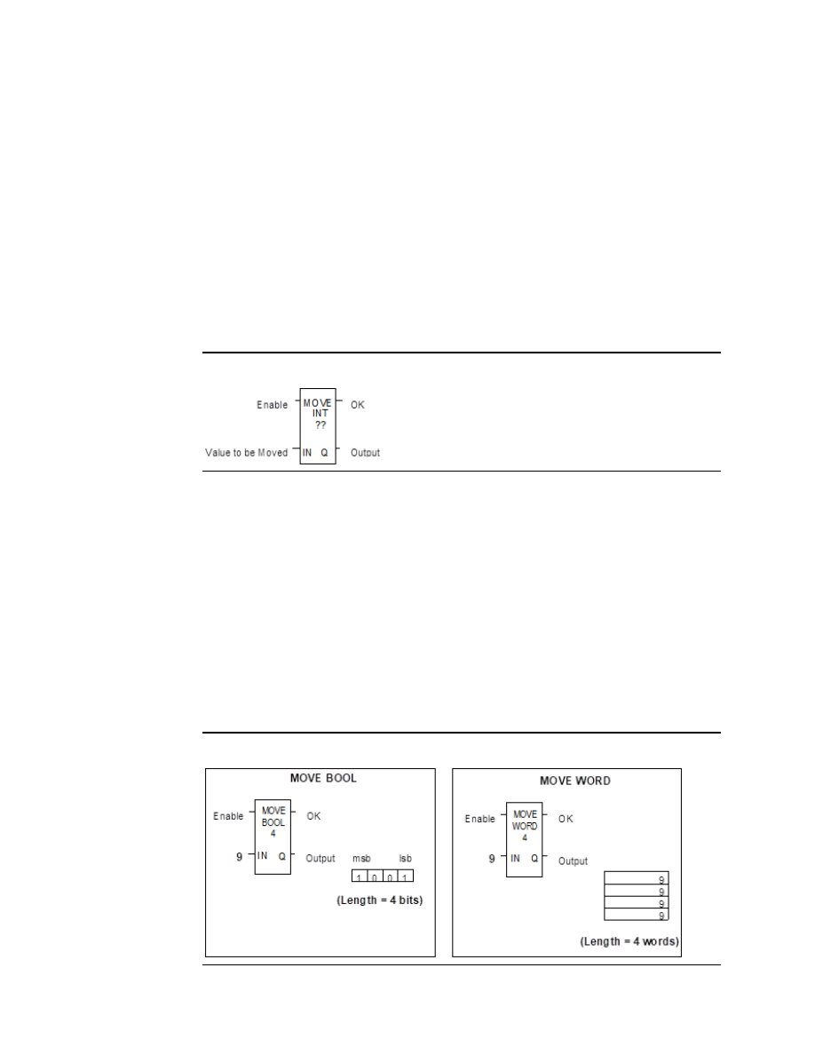
The MOVE function copies data as individual bits from one location to another.  Because the 
data is copied in bit format, the new location does not need to be the same data type as the 
original. 

When the Move function receives power flow, it copies data from input parameter IN to 
output  parameter  Q  as  bits.    If  data  is  moved  from  one  location  in  discrete  memory  to 
another,  (for  example,  from  %I  memory  to  %T  memory),  the  transition  information 
associated with the discrete memory elements is updated to indicate whether or not the 
Move operation caused any discrete memory elements to change state.  Data at the input 
parameter does not change unless there is an overlap in the source and destination. 

Figure 276 


Note that if an array of Bit-type data specified in the Q parameter does not include all the 
bits in a byte, the transition bits associated with that byte (which are not in the array) are 
cleared when the Move function receives power flow. 

The input IN can be either a reference for the data to be moved or a constant.  If a constant 
is  specified,  then  the  constant  value  is  placed  in  the  location  specified  by  the  output 
reference.  For example, if a constant value of 4 is specified for IN, then 4 is placed in the 
memory location specified by Q.  If the length is greater than 1 and a constant is specified, 
then  the  constant  is  placed  in  the  memory  location  specified  by  Q  and  the  locations 
following, up to the length specified. Do not allow overlapping of IN and Q parameters.  

The result of the Move depends on the data type selected for the function, as shown below. 
For example, if the constant value 9 is specified for IN and the length is 4, then 9 is placed in 
the bit memory location specified by Q and the three locations following: 

Figure 277 


The function passes power to the right whenever power is received. 

User Manual 

Chapter 23 

GFK-1645M 

Dec 2019 


Instruction Set Reference 

451 

Parameters for the Move Data Function 

Input/ 
Output 

Choices 

Description 

enable 

flow 

When the function is enabled, the move is performed. 

Length 


The  number  of  bits,  words,  or  double  words  of  data  to  be 
copied. This is the length of IN. Length must be from 1 to 256 
for all types except BOOL. If IN is a constant and Q is type BOOL, 
the length must be between 1 and 16. If IN is type BOOL, the 
length must be between 1 and 256 bits. 

IN 

I, Q, M, T, G, R, AI, AQ, 
constant 
For bit or word data 
only: S 
For real data: R, AI, AQ 

IN  contains  the  value  to  be  moved.    For  MOVE  BOOL,  any 
discrete reference may be used; it does not need to be byte 
aligned.    However,  16  bits,  beginning  with  the  reference 
address specified, are displayed online. 

ok 

flow, none 

The OK output is energized whenever the function is enabled. 

I, Q, M, T, G, R, AI, AQ,  
For bit/ word data: SA, 
SB, SC 
For real data: R, AI, AQ 

When the move is performed, the value at IN is written to Q.  
For MOVE BOOL, any discrete reference may be used; it does 
not need to be byte aligned.  However, 16 bits, beginning with 
the reference address specified, are displayed online. 

23.3.2


Data Move Functions 
Block Move 

The Block Move function copies a block of seven constants to a specified location. When the 
Block  Move  function  receives  power  flow,  it  copies  the  constant  values  into  consecutive 
locations beginning at the destination specified in output Q. The function passes power to 
the right whenever power is received. 

Figure 278 


User Manual 

Chapter 23 

GFK-1645M 

Dec 2019 


Instruction Set Reference 

452 

Parameters of the Block Move Function 

Input/ 
Output 

Choices 

Description 

enable 

flow 

When the function is enabled, the block move is performed. 

IN1 to 
IN7 

constant 

IN1 through IN7 contain seven constant values. 

ok 

flow, none 

The OK output is energized whenever the function is enabled. 

I, Q, M, T, G, R, AI, AQ 
For Word data: SA, SB, 
SC 
For Real data: R, AI, 
AQ 

Output Q contains the first element of the moved array.  IN1 is 
moved to Q. 

Revision  2.6  and  later  Micro-64  PLCs,  Micro-20  PLCs  and  Micro-40  PLCs  support  both 
DWORD and DINT data types for a Block Move. Other Micro PLC models do not support 32-
bit data types. 

Example 

In the example, when the enabling input represented by the nickname FST_SCN is ON, the 
Block Move function copies the input constants into memory locations %R0010

16. 

Figure 279 


User Manual 

Chapter 23 

GFK-1645M 

Dec 2019 


Instruction Set Reference 

453 

23.3.3


Data Move Functions 
Block Clear 

The Block Clear function fills a specified block of data with zeros. When the function receives 
power flow, it writes zeros into the memory location beginning at the reference specified by 
IN.    When  the  data  to  be  cleared  is  from  discrete  memory  (%I,  %Q,  %M,  %G,  or  %T),  the 
transition information associated with the references is also cleared. 

The function passes power to the right whenever power is received. 

Figure 280 


Parameters of the Block Clear Function 

Input/ 
Output 

Choices 

Description 

enable 

flow 

When the function is enabled, the array is cleared. 

IN 

I, Q, M, T, SA, SB, SC, G, 
R, AI, AQ 

IN contains the first word of the array to be cleared. The 
length of IN must be between 1 and 256 words. 

Length 


The number of words that will be cleared. This is the length 
of IN. 

ok 

flow, none 

The OK output is energized whenever the function is 
enabled. 

Example 

In the example, at power-up, 32 words of %Q memory (512 points) beginning at %Q0001 
are filled with zeros. %Q is defined as WORD of length 32. 

Figure 281 


User Manual 

Chapter 23 

GFK-1645M 

Dec 2019 


Instruction Set Reference 

454 

23.3.4


Data Move Functions 
Shift Register 

The  Shift  Register  function  shifts  one  or  more  data  words  or  data  bits  from  a  reference 
location into a specified area of memory.  For example, one word might be shifted into an 
area of memory with a specified length of five words.  As a result of this shift, another word 
of data would be shifted out of the end of the memory area. 

The  reset  input  (R)  takes  precedence  over  the  function  enable  input.  When  the  reset  is 
active, all references beginning at the shift register (ST) up to the length specified for LEN, 
are filled with zeros. 

If  the  function  receives  power  flow  and  reset  is  not  active,  each  bit  or  word  of  the  shift 
register  is  moved  to  the  next  highest  reference.    The  last  element  in  the  shift  register  is 
shifted into Q.  The highest reference of the shift register element of IN is shifted into the 
vacated element starting at ST.  The contents of the shift register are accessible throughout 
the program because they are overlaid on absolute locations in logic addressable memory. 

Figure 282 


Parameters of the Shift Register Function 

Input/ 
Output 

Choices 

Description 

enable 

flow 

When enable is energized and R is not, the shift is performed. 

Length 

1 to 256 bits 
or words. 

The length of the shift register  in bits or words. Length is defined as the 
length of IN. 

flow 

When R is energized, the shift register located at ST is filled with zeros. 

IN 

I, Q, M, T, S, G, 
R, AI, AQ, 
constant 

IN contains the value to be shifted into the first bit or word of the shift 
register.  For SHFR BIT,  any discrete reference may be used; it does not 
need to be byte aligned.   

ST 

I, Q, M, T, SA, 
SB, SC, G, R, 
AI, AQ 

ST contains the first bit or word of the shift register.  For SHFR BIT, any 
discrete reference may be used; it does not need to be byte aligned.  

ok 

flow, none 

OK is energized whenever the function is enabled and R is not enabled. 

I, Q, M, T, SA, 
SB, SC, G, R, 
AI, AQ 

Output Q contains the bit or word shifted out of the shift register.  For 
SHFR BIT, any discrete reference may be used; it does not need to be 
byte aligned.   

User Manual 

Chapter 23 

GFK-1645M 

Dec 2019 


Instruction Set Reference 

455 

CAUTION 

The use of overlapping input and output reference address ranges in multi-word functions 
is not recommended; it may produce unexpected results. 

Example 1: 

In the example, the shift register operates on register memory locations %R0001 through 
%R0100.  (%R0001 is defined as type Word of length 100). When the reset reference CLEAR 
is active, the Shift Register words are set to zero.  

When the NXT_CYC reference is active and CLEAR is not active, the word from output status 
table location %Q0033 is shifted into the Shift Register at %R0001.  The word shifted out of 
the Shift Register from %R0100 is stored in output %M0005. 

Figure 283 


Example 2:  

In  this  example,  the  Shift  Register  operates  on  memory  locations  %M0001  through 
%M0100.  (%M0001 is defined as type Boolean of length 100). When the reset reference 
CLEAR is active, the Shift Register function fills %M0001 through %M0100 with zeros.  

When  NXT_CYC  is  active  and  CLEAR  is  not,  the  Shift  Register  function  shifts  the  data  in 
%M0001 to %M0100 down by one bit.  The bit in %Q0033 is shifted into %M0001 while the 
bit shifted out of %M0100 is written to %M0200. 

Figure 284 


User Manual 

Chapter 23 

GFK-1645M 

Dec 2019 


Instruction Set Reference 

456 

23.3.5


Data Move Functions 
Communication Request 

The Communication Request (COMMREQ) function is use for specialized communications.  
Many types of COMMREQs have been defined. The information below describes only the 
basic format of the function. 

When the function receives power flow, a command block of data is sent to the specified 
module.  After sending the COMMREQ, the program can either suspend execution, and wait 
for a reply for a maximum waiting period specified in the command, or resume immediately. 

Figure 285 


Parameters of the COMMREQ Function 

Input/ 
Output 

Choices 

Description 

enable 

flow 

When the function is energized, the communications request is 
performed.  

IN 

R, AI, AQ 

IN contains the first word of the command block. 

SYSID 

I, Q, M, T, G, R, AI, AQ, 
constant 

SYSID contains the rack number (most significant byte) and slot 
number (least significant byte) of the target device. 

TASK 

R, AI, AQ, constant 

TASK contains the task ID of the process on the target device. 

FT 

flow, none 

FT is energized if an error is detected processing the COMMREQ: 
The specified target address is not present (SYSID).  
The specified task is not valid for the device (TASK).  
The data length is 0.  

The device’s status pointer address (in the command block) does 

not exist.   


User Manual 

Chapter 23 

GFK-1645M 

Dec 2019 


Instruction Set Reference 

457 

Command Block for the COMMREQ Function 

The  Command  Block  starts  at  the  reference  specified  in  COMMREQ  parameter  IN.  The 
length of the Command Block depends on the amount of data sent to the device. 

The  Command  Block  contains  the  data  to  be  communicated  to  the  other  device,  plus 
information  related  to  the  execution  of  the  COMM  REQ.  The  Command  Block  has  the 
following structure:  

address 

Length (in words) 

address + 1 

Wait/No Wait Flag 

address + 2 

Status Pointer Memory 

address + 3 

Status Pointer Offset 

address + 4 

Idle Timeout Value 

address + 5 

Maximum Communication Time 

address + 6 to 
address + 133 

Data Block 

Example 

In the example, when enabling input %M0020 is ON, a Command Block starting at %R0016 
is sent to communications task 1 in the device located at rack 1, slot 2 of the PLC.  If an error 
occurs processing the COMMREQ, %Q0100 is set. 

Figure 286 


User Manual 

Chapter 23 

GFK-1645M 

Dec 2019 


Instruction Set Reference 

458 

23.4


Data Type Conversion Functions 

The Data Type Conversion functions are used to change a data item from one number type 
to another. Many  programming instructions, such as math functions, must be used with 
data of one type. 


Convert data to BDC-4 


Convert data to signed integer 


Convert data to double-precision integer 


Convert data to Real 


Convert data to Word 


Round a Real number toward zero (TRUN) 

23.4.1


Data Type Conversion Functions 
Convert Signed Integer Data to BCD-4 

The Convert to BCD-4 function outputs the four-digit BCD equivalent of signed integer data. 
The original data is not changed by this function.  The output data can be used directly as 
input for another program function. 

Data  can  be  converted  to  BCD  format  to  drive  BCD-encoded  LED  displays  or  presets  to 
external devices such as high-speed counters. 

When  the  function  receives  power  flow,  it  performs  the  conversion,  making  the  result 
available via output Q.  The function passes power flow when power is received, unless the 
specified conversion would result in a value that is outside the range 0 to 9999. 

Figure 287 


Parameters of the Convert to BCD-4 Function 

Input/ 
Output 

Choices 

Description 

enable 

flow 

When the function is enabled, the conversion is performed. 

IN 

I, Q, M, T, G, R, AI, AQ, 
constant 

IN contains a reference for the integer value to be converted to 
BCD-4. 

OK 

flow, none 

The OK output is energized when the function is performed 
without error. 

I, Q, M, T, G, R, AI, AQ  Output Q contains the BCD-4 form of the original value in IN. 


User Manual 

Chapter 23 

GFK-1645M 

Dec 2019 


Instruction Set Reference 

459 

Example 

In  the  example,  whenever  input  %I0002  is  set  and  no  errors  exist,  the  integer  at  input 
location %I0017 through %I0032 is converted to four BCD digits, and the result is stored in 
memory locations %Q0033 through %Q0048.  Coil %Q1432 is used to check for successful 
conversion. 

Figure 288 


23.4.2


Data Type Conversion Functions 
Convert to Signed Integer  

The  Convert  to  Signed  Integer  function  outputs  the  integer  equivalent  of  BCD-4  or  Real 
data.  The original data is not changed by this function. The output data can be used as input 
for another program function. 

When  the  function  receives  power  flow,  it  performs  the  conversion,  making  the  result 
available  via  output  Q.  The  function  always  passes  power  flow  when  power  is  received, 
unless the data is out of range. 

Figure 289 


Parameters of the Convert to Signed Integer Function 

Input/ 
Output 

Choices 

Description 

enable 

flow 

When the function is enabled, the conversion is 
performed. 

IN 

For BCD-4: I, Q, M, T, G, R, AI, AQ, 
constant 
For REAL: R, AI, AQ 

IN contains a reference for the BCD-4, REAL, or 
Constant value to be converted to integer. 

ok 

flow, none 

The OK output is energized whenever enable is 
energized, unless the data is out of range or NaN 
(Not a Number). 

For BCD-4: I, Q, M, T, G, R, AI, AQ 
For REAL: R, AI, AQ 

Output Q contains the integer form of the original 
value in IN. 


User Manual 

Chapter 23 

GFK-1645M 

Dec 2019 


Instruction Set Reference 

460 

Example 

In the example, whenever input %I0002 is set, the BCD-4 value in PARTS is converted to a 
signed integer and passed to the Addition function, where it is added to the signed integer 
value represented by the reference RUNNING.  The sum is output by the Addition function 
to the reference TOTAL. 

Figure 290 


23.4.3


Data Type Conversion Functions 
Convert to Double Precision Signed Integer  

The  Convert  to  Double  Precision  Signed  Integer  function  outputs  the  double  precision 
signed integer equivalent of real data.  The original data is not changed by this function. The 
output data can be used directly as input for another program function. 

When  the  function  receives  power  flow,  it  performs  the  conversion,  making  the  result 
available  via  output  Q.  The  function  always  passes  power  flow  when  power  is  received, 
unless the real value is out of range. 

Figure 291 


Note that loss of precision can occur when converting from Real-type data to Double-
Precision Integer, because Real data has 24 significant bits.  

Parameters of the Convert to Double Precision Signed 
Integer Function 

Input/ 
Output 

Choices 

Description 

enable 

flow 

When the function is enabled, the conversion is performed.  

IN 

I, Q, M, T, G, R, AI, AQ, 
constant 

Constant or reference for the value to be converted 

ok 

flow, none 

OK is energized whenever enable is energized, unless the real 
value is out of range.  

R, AI, AQ 

Reference that contains the double precision signed integer 
form of the original value.  

User Manual 

Chapter 23 

GFK-1645M 

Dec 2019 


Instruction Set Reference 

461 

Example 

In the example, whenever input %I0002 is set, the integer value at input location %I0017 is 
converted to a double precision signed integer and the result is placed in location %R0001. 
The output %Q1001 is set whenever the function executes successfully. 

Figure 292 


23.4.4


Data Type Conversion Functions 
Convert to Real Data  

The Convert to Real function outputs the real value equivalent of the input data.  The original 
data  is  not  changed  by  this  function.    The  output  data  can  be  used  directly  as  input  for 
another program function. 

When  the  function  receives  power  flow,  it  performs  the  conversion,  making  the  result 
available via output Q.  The function passes power flow when power is received, unless the 
specified conversion would result in a value that is out of range. 

Note that loss of precision can occur when converting from Double-Precision Integer to Real 
data, because since the number of significant bits is reduced to 24. 

Figure 293 


Parameters of the Convert to Real Function 

Input/ 
Output 

Choices 

Description 

enable 

flow 

When the function is enabled, the conversion is performed.  

IN 

R, AI, AQ, constant 
For INT only: I, Q, M, 
T, G 

IN contains a reference for the integer value to be converted to 
Real.  

ok 

flow, none 

OK is energized when the function is performed without error.  

Q  

R, AI, AQ 

The Real form of the original value in IN.  


User Manual 

Chapter 23 

GFK-1645M 

Dec 2019 


Instruction Set Reference 

462 

Example 

In the example, the integer value of input IN is 678.  The result value placed in %T0016 is 
678.000. 

Figure 294 


23.4.5


Data Type Conversion Functions 
Convert Real Data to Word Data  

The Convert to Word function outputs the Word equivalent of Real data.  The original data 
is not changed by this function. 

When  the  function  receives  power  flow,  it  performs  the  conversion,  making  the  result 
available via output Q. The function passes power flow when power is received, unless the 
specified conversion would result in a value that is outside the range 0 to FFFFh. 

Figure 295 


Parameters of the Convert to Word Function 

Input/ 
Output 

Choices 

Description 

enable 

flow 

When the function is enabled, the conversion is performed.  

IN 

R, AI, AQ, constant 

IN contains a reference for the value to be converted to Word 
type.  

ok 

flow, none 

OK is energized when the function is performed without error.  

I, Q, M, T, G, R, AI, AQ  Contains the unsigned integer form of the original value in IN.  

Example 

Figure 296 


User Manual 

Chapter 23 

GFK-1645M 

Dec 2019 


Instruction Set Reference 

463 

23.4.6


Data Type Conversion Functions 
Truncate Real Number  

The Truncate function copies a Real number and rounds the copied number down to an 
integer or double precision integer.  The original data is not changed by this function.  The 
output data can be used directly as input for another program function. 

When  the  function  receives  power  flow,  it  performs  the  conversion,  making  the  result 
available via output Q.  The function passes power flow when power is received, unless the 
specified conversion would result in a value that is out of range or unless IN is not a number. 

Figure 297 


Parameters of the Truncate Function 

Input/ 
Output 

Choices 

Description 

enable 

flow 

When the function is enabled, the conversion is performed.  

IN 

R, AI, AQ, constant 

IN contains a reference for the real value to be truncated.  

ok 

flow, none 

The OK output is energized when the function is performed 
without error, unless the value is out of range or IN is NaN.  

R, AI, AQ 
For integer only: I, Q, M, 
T, G 

Q contains the truncated INT or DINT value of the original 
value in IN.  

Example 

In the example, the displayed constant is truncated, and the integer result 562 is placed in 
%T0001. 

Figure 298 


User Manual 

Chapter 23 

GFK-1645M 

Dec 2019 


Instruction Set Reference 

464 

23.5


Math and Numerical Functions 

This section describes the Math and Numerical functions of the Instruction Set:  


Standard Math Functions: Addition, Subtraction, Multiplication, Division 


Modulo Division 


Scaling Function 


Square Root 


Trigonometric functions 


Logarithmic/Exponential functions 


Convert to Degrees 


Convert to Radians 

23.5.1


Converting Data for the Math and Numerical Functions 

The program may need to include logic to convert data to a different type before using a 
Math or Numerical function. The description of each function includes information about 
appropriate  data  types.  The  section  Data  Type  Conversion  Functions  explains  how  to 
convert data to a different type. 

23.5.2


Math and Numerical Functions 
Add, Subtract, Multiply, Divide 

The standard math functions are Addition, Subtraction, Multiplication, and Division.  The 
Division function rounds down; it does not round to the closest integer. (For example, 24 
DIV 5 = 4.) 

When a math function receives power flow, the appropriate operation is performed on input 
parameters IN1 and IN2.  Parameters IN1, IN2, and the output Q must be the same data 
type. 

Figure 299 


The standard math functions pass power if there is no math overflow.  If an overflow occurs, 
the result is the largest value with the proper sign and no power flow. 


User Manual 

Chapter 23 

GFK-1645M 

Dec 2019 


Instruction Set Reference 

465 

Parameters of the Standard Math Functions 

Input/ 
Output 

Choices 

Description 

enable 

flow 

When the function is enabled, the operation is performed. 

IN1 

All data types: R, AI, AQ, 
constant 
INT data type only: I, Q, 
M, T, G 

IN1 contains a constant or reference for the first value used 
in the operation.  (IN1 is on the left side of the 
mathematical equation, as in IN1 + IN2). 
Range for constants in double-precision signed integer 
operations is minimum/maximum DINT. 

IN2 

All data types: R, AI, AQ, 
constant 
INT data type only: I, Q, 
M, T, G 

IN2 contains a constant or reference for the second value 
used in the operation.  (IN2 is on the right side of the 
mathematical equation, as in IN1 + IN2). Range for 
constants in double-precision signed integer operations is 
minimum/maximum DINT. 

ok 

flow, none 

The OK output is energized when the function is performed 
without overflow, unless an invalid operation occurs. 

All data types: R, AI, AQ 
INT only: I, Q, M, T, G 

Output Q contains the result of the operation. 

Data Types for Standard Math Functions 

Standard math functions operate on these types of data:  

INT 

Signed integer 

DINT 

Double precision signed integer 

REAL 

Floating Point 

The input and output parameter data types must be the same (16 bits or 32 bits).   

23.5.3


Math and Numerical Functions 
Add, Subtract, Multiply, Divide  

Avoiding Overflows 

Be careful to avoid overflows when using Multiplication and Division functions.   

If you have to convert Integer to Double-Precision Integer values, remember that the CPU 

uses standard 2’s complement with the sign extended to the highest bit of the second word. 

You must check the sign of the low 16-bit word and extend it into the second 16 bit word. If 
the most significant bit in a 16-bit INT word is 0 (positive), move a 0 to the second word. If 
the most significant bit in a 16-bit word is 

1 (negative), move a 

1 or hex 0FFFFh to the 

second word. 

Converting from Double-Precision Integer to Integer data is easier, because the low 16-bit 
word (first register) is the integer portion of a Double-Precision Integer 32-bit word. The 
upper 16 bits or second word should be either a 0 (positive) or 

1 (negative) value or the 

Double-Precision Integer number will be too big to convert to 16 bits. 


Content      ..     29      30      31      32     ..