EMERSON PACSystems VersaMax MICRO PLC & NANO PLC. USER MANUAL (2019) - page 32
 

  Index      Manuals     EMERSON PACSystems VersaMax MICRO PLC & NANO PLC. USER MANUAL (2019)


Search            copyright infringement  


Content      ..     30      31      32      33     ..


EMERSON PACSystems VersaMax MICRO PLC & NANO PLC. USER MANUAL (2019) - page 32


User Manual 

Chapter 23 

GFK-1645M 

Dec 2019 


Instruction Set Reference 

466 

Example 

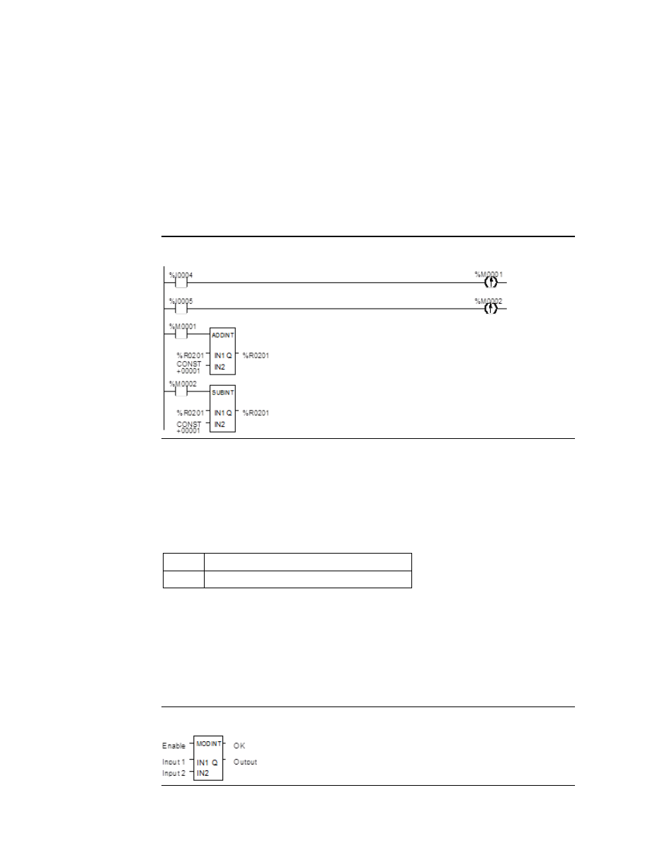
This example uses the Addition and Subtraction functions to keep track of the number of 
parts in a temporary storage area. Each time a part enters the storage area, power flows 
through relay %I0004 to a positive transition coil with reference %M0001. Relay %M0001 
then enables the Addition function, adding the (constant) value 1 to the current total value 
in %R0201. 

Each time a part leaves the storage area, power flows through relay %I0005 to a positive 
transition  coil  with  reference  %M0002.  Relay  %M0002  then  enables  the  Subtraction 
function, subtracting the (constant) value 1 from the current total value in %R0201. 

Figure 300 


23.5.4


Math and Numerical Functions 
Modulo Division  

The Modulo Division function divides one value by another of the same data type, to obtain 
the remainder.  The sign of the result is always the same as the sign of input parameter IN1. 
The Modulo function operates on these types of data:  

INT 

Signed integer 

DINT 

Double precision signed integer 

When the function receives power flow, it divides input IN1 by input IN2.  These parameters 
must be the same data type.  Output Q is calculated using the formula:  

Q = IN1-((IN1 DIV I2) * I2) 

The division produces an integer number.  Q is the same data type as inputs IN1 and IN2.  OK 
is always ON when the function receives power flow, unless there is an attempt to divide by 
zero.  In that case, it is set OFF.  

Figure 301 


User Manual 

Chapter 23 

GFK-1645M 

Dec 2019 


Instruction Set Reference 

467 

Parameters of the Modulo Division Function 

Input/ 
Output 

Choices 

Description 

enable 

flow 

When the function is enabled, the operation is performed. 

IN1 

All data types: R, AI, AQ, 
constant 
INT data type only: I, Q, 
M, T, G 

IN1 contains a constant or reference for the value to be 
divided by IN2. Range for constants in double precision 
signed integer operations is minimum/maximum DINT. 

IN2 

All data types: R, AI, AQ, 
constant 
INT data type only: I, Q, 
M, T, G 

IN2 contains a constant or reference for the value to be 
divided into IN1. Range for constants in double precision 
signed integer operations is minimum/maximum DINT. 

ok 

flow, none 

The OK output is energized when the function is performed 
without overflow. 

All data types: R, AI, AQ 
INT data type only: I, Q, 
M, T, G 

Output Q contains the result of dividing IN1 by IN2 to 
obtain a remainder. 

Example 

In the example, the remainder of the integer division of BOXES into PALLETS is placed into 
NT_FULL whenever %I0001 is ON. 

Figure 302 


23.5.5


Math and Numerical Functions Scaling 

The Scaling function scales an input parameter and places the result in an output location. 
For integer-type data, all parameters must be integer-based (signed). For word-type data, 
all parameters must be word-based (unsigned). 

Figure 303 


User Manual 

Chapter 23 

GFK-1645M 

Dec 2019 


Instruction Set Reference 

468 

Parameters of the Scaling Function 

Input/ 
Output 

Choices 

Description 

enable 

flow 

When the function is enabled, the operation is performed. 

IHI 
ILO 

R ,AI, AQ, 
constant 

IHI and ILO contain a constant or reference for the upper and lower limits 
of the unscaled data. These limits, together with the values for OHI  and 
OLO, are used to calculate the scaling factor that will be applied to the input 
value IN. 

OHI 
OLO 

R ,AI, AQ, 
constant 

OHI and OLO contain a constant or reference for the upper and lower limits 
of the scaled data.  

IN 

R, AI, AQ, 
constant 

IN contains a constant or reference for the actual value to be scaled. 

ok 

flow, none 

The  OK  output  is  energized  when  the  function  is  performed  without 
overflow. 

OUT 

R, AI, AQ 

Output OUT contains the scaled equivalent of the input value. 

Example 

In the example, the registers %R0120 through %R0123 are used to store the high and low 
scaling values. The input value to be scaled is analog input %AI0017. The scaled output data 
is used to control analog output %AQ0017. The scaling is performed whenever %I0001 is 
ON. 

Figure 304 


User Manual 

Chapter 23 

GFK-1645M 

Dec 2019 


Instruction Set Reference 

469 

23.5.6


Math and Numerical Functions Square Root  

The Square Root function finds the square root of a value. When the function receives power 
flow, the value of output Q is set to the integer portion of the square root of the input IN.  
The output Q must be the same data type as IN. 

The Square Root function operates on these types of data:  

INT 

Signed integer 

DINT 

Double precision signed integer 

REAL 

Floating Point 

OK is set ON if the function is performed without overflow, unless one of these invalid REAL 
operations occurs:  


IN < 0 


IN is NaN (Not a Number) 

Otherwise, OK is set OFF. 

Figure 305 


Parameters of the Square Root Function 

Input/ 
Output 

Choices 

Description 

enable 

flow 

When  the  function  is  enabled,  the  operation  is 
performed. 

IN 

All data types: R, AI, AQ, constant 
INT data type only: I, Q, M, T, G 

A constant or reference for the value whose square 
root is to be calculated.  If IN is less than zero, the 
function  will  not  pass  power  flow.  Range  for 
constants  is  minimum/maximum  DINT  for  double 
precision signed integer operations. 

ok 

flow, none 

The  OK  output  is  energized  when  the  function  is 
performed  without  overflow,  unless  an  invalid 
operation occurs. 

All data types: R, AI, AQ 
INT data type only: I, Q, M, T, G 

Output Q contains the square root of IN. 


User Manual 

Chapter 23 

GFK-1645M 

Dec 2019 


Instruction Set Reference 

470 

Example 

In the example, the square root of the integer number located at %AI001 is placed into the 
result located at %R0003 whenever %I0001 is ON. 

Figure 306 


23.5.7


Math and Numerical Functions Trigonometric Functions 

There are six Trigonometric functions: Sine, Cosine, Tangent, Inverse Sine, Inverse Cosine, 
and Inverse Tangent. 

Sine, Cosine, and Tangent 

When a Sine, Cosine, or Tangent function receives power flow, it operates on IN, whose units 
are radians, and stores the result in output Q.  Both IN and Q are floating-point values. 

Figure 307 


The Sine, Cosine, and Tangent functions accept a broad range of input values, where  

263 < IN <+263, (263 = 9.22x10¹⁸) 


User Manual 

Chapter 23 

GFK-1645M 

Dec 2019 


Instruction Set Reference 

471 

Inverse Sine, Cosine, and Tangent 

When an Inverse Sine, Cosine, or Tangent function receives power flow, it operates on IN 
and stores the result in output Q, whose units are radians.  Both IN and Q are floating-point 
values. 

The Inverse Sine and Cosine functions accept a narrow range of input values, where 

-1 < IN < 1. 

Given a valid value for the IN parameter, the Inverse Sine Real function produces a result Q 
such that:  

ASIN(IN) = -

π/2 ≤ Q ≤ π/2.


The Inverse Cosine Real function produces a result Q such that:  

ACOS(IN) = 0 ≤ Q ≤ π.


The Inverse Tangent function accepts the broadest range of input values, where 

-

∞ ≤ IN ≤ +∞.


Given a valid value for the IN parameter, the Inverse Tangent Real function produces a 
result Q such that: 

ATAN(IN) = -

π/2 ≤ Q ≤ π/2.


Parameters of the Trigonometric Functions 

Input/Output  Choices 

Description 

enable 

flow 

When the function is enabled, the operation is performed.  

IN 

R, AI, AQ, 
constant 

IN contains the constant or reference real value to be operated 
on.  

ok 

flow, none 

OK is energized when the function is performed without 
overflow, unless an invalid operation occurs and/or IN is NaN.  

R, AI, AQ 

Output Q contains the trigonometric value of IN.  

Example 

In the example, the Cosine of the value in %R0001 is placed in %R0033. 

Figure 308 


User Manual 

Chapter 23 

GFK-1645M 

Dec 2019 


Instruction Set Reference 

472 

23.5.8


Math and Numerical Functions Logarithmic / 
Exponential Functions 

When  a  Logarithmic  or  Exponential  function  receives  power  flow,  it  performs  the 
appropriate logarithmic/exponential operation on the Real value in input IN and places the 
result in output Q. 


For the Base 10 Logarithm (LOG) function, the base 10 logarithm of IN is placed in 
Q. 


For the Natural Logarithm (LN) function, the natural logarithm of IN is placed in Q. 


For the Power of E (EXP) function, e is raised to the power specified by IN and the 
result is placed in Q. 


For  the  Power  of  X  (EXPT)  function,  the  value  of  input IN1  is  raised  to  the  power 
specified by the value IN2 and the result is placed in output Q.  (The EXPT function 
has three input parameters and two output parameters.) 

The OK output receives power flow unless the input is NaN (Not a Number) or is negative. 

Figure 309 


Parameters of the Logarithmic/Exponential Functions 

Input/ 
Output 

Choices 

Description 

enable 

flow 

When the function is enabled, the operation is performed.  

IN or 
IN1, IN2 

R, AI, AQ, 
constant 

For EXP, LOG, and LN, IN contains the real value to be operated on.  
The EXPT function has two inputs, IN1 and IN2. For EXPT, IN1 is the 
base value and IN2 is the exponent. 

ok 

flow, none 

OK is energized when the function is performed without overflow, 
unless an invalid operation occurs and/or IN is NaN or is negative.  

R, AI, AQ 

Output Q contains the logarithmic/exponential value of IN.  

Example of the EXPT Function 

In the example, the value of %AI001 is raised to the power of 2.5 and the result is placed in 
%R0001. 

Figure 310 


User Manual 

Chapter 23 

GFK-1645M 

Dec 2019 


Instruction Set Reference 

473 

23.5.9


Math and Numerical Functions Radian Conversion 
Functions 

When Degree/Radian Conversion function receives power flow, the appropriate conversion 
(radians to degrees or degrees to radians) is performed on the Real value in input IN and the 
result is placed in output Q. 

The OK output will receive power flow unless IN is NaN (Not a Number). 

Figure 311 


Parameters of the Radian Conversion Function 

Input/Output  Choices 

Description 

enable 

flow 

When the function is enabled, the operation is performed.  

IN 

R, AI, AQ, constant  IN contains the real value to be operated on.  

ok 

flow, none 

The OK output is energized when the function is 
performed without overflow, unless IN is NaN.  

R, AI, AQ 

Output Q contains the converted value of IN.  

Example 

In the example, +1500 is converted to DEG and is placed in %R0001. 

Figure 312 


User Manual 

Chapter 23 

GFK-1645M 

Dec 2019 


Instruction Set Reference 

474 

23.6


Relational Functions 

The Relational functions can be used to compare two numbers and to determine whether a 
number lies within a specified range. 


Equal  

Test two numbers for equality 


Not Equal  

Test two numbers for non-equality 


Greater Than  

Test whether one number is greater than another 


Greater Than or Equal   Test whether one number is greater than or equal to 

another 


Less Than  

Test whether one number is less than another 


Less Than or Equal  

Test whether one number is less than or equal to another 


Range 

Tests whether one number lies between two other 
numbers 

When  the  function  receives  power  flow,  it  compares  input  IN1  to  input  IN2.    These 
parameters must be the same data type. 

Figure 313 


If inputs IN1 and IN2 match the specified relational condition, output Q receives power 
flow and is set ON (1); otherwise, it is set OFF (0). 

23.6.1


Data Types for Relational Functions 

Relational functions operate on these types of data:  

INT 

Signed integer 

DINT 

Double precision signed integer 

REAL 

Floating Point 

The %S0020 bit is set ON when a relational function using Real data executes successfully.  
It is cleared when either input is NaN (Not a Number). 


User Manual 

Chapter 23 

GFK-1645M 

Dec 2019 


Instruction Set Reference 

475 

23.6.2


Relational Functions Equal, Not Equal, Less Than, 
Less/Equal, Greater Than, Greater/Equal 

Parameters for the Relational Functions 

Input/ 
Output 

Choices 

Description 

enable 

flow 

When the function is enabled, the operation is performed. 

IN1  

R, AI, AQ, constant 
For INT data only: I, Q, 
M, T, G 

IN1 contains a constant or reference for the first value to be 
compared.  IN1 must be a valid number. Constants must be 
integers for double precision signed integer operations. 
IN1 is on the left side of the relational equation, as in IN1 < IN2. 

IN2 

R, AI, AQ, constant 
For INT data only: I, Q, 
M, T, G 

IN2 contains a constant or reference for the second value to be 
compared. IN2 must be a valid number.  Constants must be 
integers for double precision signed integer operations. 
IN2 is on the right side of the relational equation, as in IN1 < 
IN2.  

flow, none 

Output Q is energized when IN1 and IN2 match the specified 
relation. 

Example 

In the example, two double precision signed integers are tested for equality. When the relay 
%I0001  passes  power  flow  to  the  LE  (Less  or  Equal)  function,  the  value  presently  in  the 
reference  nicknamed  PWR_MDE  is  compared  to  the  value  presently  in  the  reference 
BIN_FUL. If the value in PWR_MDE is less than or equal to the value in BIN_FUL, coil %Q0002 
is turned on. 

Figure 314 


User Manual 

Chapter 23 

GFK-1645M 

Dec 2019 


Instruction Set Reference 

476 

23.6.3


Relational Functions Range 

The Range function determines if a value is within the range of two numbers. 

Data Types for the Range Function 

The Range function operates on these types of data:  

INT 

Signed integer (default). 

DINT 

Double precision signed integer. 

WORD 

Word data type. 

When the Range function is enabled, it compares the value of input IN against the range 
specified by limits L1 and L2. Either L1 or L2 can be the high or low limit. When the value is 
within  the  range  specified  by  L1  and  L2,  inclusive,  output  parameter  Q  is  set  ON  (1).  
Otherwise, Q is set OFF (0).  

Figure 315 


Parameters for the Range Function 

Input/ 
Output 

Choices 

Description 

enable 

flow 

When the function is enabled, the operation is performed. 

L1 

R, AI, AQ, constant 
INT and WORD only: I, Q, 
M, T, G 

L1 contains the start point of the range. 
Constants must be integer values for double precision 
signed integer operations. 

L2 

R, AI, AQ, constant 
INT and WORD only: I, Q, 
M, T, G 

L2 contains the end point of the range. 
Constants must be integer values for double precision 
signed integer operations. 

IN 

R, AI, AQ 
INT and WORD only: I, Q, 
M, T, G 

IN contains the value to be compared against the range 
specified by L1 and L2. 

flow, none 

Output Q is energized when the value in IN is within the 
range specified by L1 and L2, inclusive. 


User Manual 

Chapter 23 

GFK-1645M 

Dec 2019 


Instruction Set Reference 

477 

Example 

In  this  example,  when  the  Range  function  receives  power  flow  from  relay  %I0001,  the 
function determines whether the value in %AI001 is within the range 0 to 100.  

%R0001 contains the value 100. %R2 contains the value 0. 

Figure 316 


Output coil %Q0001 is On only if the value presently in %AI0001 is within the range 0 to 100. 

IN Value %AI001 

Q State %Q0001 

< 0 

OFF 

 100 

ON 

> 100 

OFF 

23.7


Relay Functions 

Normally Open Contact   

| |


Normally Closed Contact   

|/|


Normally Open Coil   

( )


Retentive SET Coil   

(SM)


Retentive RESET Coil   

(RM)


Negated  Retentive Coil   

(/M)


Negated Coil  

(/)


Retentive Coil   

(M)


SET Coil   

(S)


RESET Coil  

(R)


Positive  Transition Coil   

(

)


Negative Transition Coil   

(

)


Vertical Link  vert 

Horizontal Link  horz  


Continuation Coil   

–––

<+> 

Continuation Contact  

<+>

–––


User Manual 

Chapter 23 

GFK-1645M 

Dec 2019 


Instruction Set Reference 

478 

Each relay contact and coil has one input and one output.  Together, they provide logic 
flow through the contact or coil.  

Input

   ----| |----   

 Output 

23.7.1


Relay Functions Normally open, Normally-closed, 
Continuation Contacts 

A contact is used to monitor the state of a reference.  Whether the contact passes power 
flow depends on the state or status of the reference being monitored and on the contact 
type.  A reference is ON if its state is 1; it is OFF if its state is 0.  

Type of Contact 

Display 

Contact Passes Power to Right: 

Normally Open 

-| |- 

When reference is ON. 

Normally Closed 

-|/|- 

When reference is OFF. 

Continuation Contact 

<+>--- 

If the preceding continuation coil is set ON. 

Normally Open Contact -| |- 

A normally open contact acts as a switch that passes power flow if the associated reference 
is ON (1). 

Normally Closed Contact -|/|- 

A normally closed contact acts as a switch that passes power flow if the associated 
reference is OFF (0). 

Example 

The example shows a rung with 10 elements having nicknames from E1 to E10.  Coil E10 is 
ON when reference E1, E2, E5, E6, and E9 are ON and references E3, E4, E7, and E8 are OFF. 

Figure 317 


Continuation Coils and Contacts 

Continuation coils and continuation contacts are used to continue relay ladder rung logic 
beyond the last column.  The state of the last executed continuation coil is the flow state 
used on the next executed  continuation contact.  If the flow of logic does not execute a 
continuation coil before it executes a continuation contact, the state of the contact is no 
flow. There can be only one continuation coil and contact per rung; the continuation contact 
must be in column 1, and the continuation coil must be in the last column. 


User Manual 

Chapter 23 

GFK-1645M 

Dec 2019 


Instruction Set Reference 

479 

23.7.2


Relay Functions Coils 

Coils are used to control discrete references.  Conditional logic must be used to control the 
flow of power to a coil.  Coils cause action directly; they do not pass power flow to the right.  
If additional logic in the program should be executed as a result of the coil condition, an 
internal reference for the coil, or a continuation coil/contact combination may be used. 

Coils are always located at the rightmost position of a line of logic:  

Figure 318 


References and Coil Checking 

When the level of coil checking is set to “single”, you can use a specific %M or %Q reference 

with only one Coil, but you can use it with one Set Coil and one Reset Coil simultaneously.  

When the level of coil checking is “warn multiple” or “multiple”, each reference can be used 

with multiple Coils, Set Coils, and Reset Coils.  With multiple usage, a reference could be 
turned On by either a Set Coil or a normal Coil and could be turned Off by a Reset Coil or by 
a normal Coil.  

Power Flow and Retentiveness 

The  following  table  summarizes  how  power  flow  to  different  types  of  coils  affects  their 
reference. The states of retentive coils are saved when power is cycled or when the PLC goes 
from Stop to Run mode.  The states of non-retentive coils are set to zero when power is 
cycled, or the PLC goes from Stop to Run mode. 

Type of Coil 

Symbol 

Power to Coil 

Result 

Normally Open  -( )- 

ON 
OFF 

Sets reference ON, non-retentive. 
Sets reference OFF, non-retentive. 

Negated 

-(/)- 

ON 
OFF 

Sets reference OFF, non-retentive. 
Sets reference ON, non-retentive. 

Retentive 

-(M)- 

ON 
OFF 

Sets reference ON, retentive. 
Sets reference OFF, retentive. 

Negated 
Retentive 

-(/M)- 

ON 
OFF 

Sets reference OFF, retentive. 
Sets reference ON, retentive. 

Positive 
Transition 

-(P)- 

OFF to ON 

If power flow into the coil was OFF the previous 
sweep and is On this sweep, sets the coil ON. 

Negative 
Transition 

-(N)- 

ON to OFF 

If power flow into the coil was ON the previous 
sweep and is OFF this sweep, sets the coil ON. 

SET 

-(S)- 

ON to OFF 

Sets reference ON until reset OFF by ( R ), non-
retentive. 
Does not change the coil state, non-retentive. 

User Manual 

Chapter 23 

GFK-1645M 

Dec 2019 


Instruction Set Reference 

480 

Type of Coil 

Symbol 

Power to Coil 

Result 

RESET 

-(R)- 

ON to OFF 

Sets reference OFF until set ON by (S), non-
retentive. 
Does not change the coil state, non-retentive. 

Retentive SET 

-(SM)- 

ON to OFF 

Sets reference ON until reset OFF by (RM), 
retentive. 
Does not change the coil state. 

Retentive 
RESET 

-(RM)- 

ON to OFF 

Sets reference OFF until set ON by (SM)-, 
retentive. 
Does not change the coil state. 

Continuation 
Coil 

----<+> 

ON 
OFF 

Sets next continuation contact ON. 
Sets next continuation contact OFF. 

A coil sets a discrete reference ON while it receives power flow.  It is non-retentive; therefore, 
it cannot be used with system status references (%SA, %SB, %SC, or %G). 

Example 

In the example, coil E3 is ON when reference E1 is ON and reference E2 is OFF. 

Figure 319 


Negated Coil 

A negated coil sets a discrete reference ON when it does not receive power flow.  It is not 
retentive, so it cannot be used with system status references (%SA, %SB, %SC, or %G).  

Example 

In the example, coil E3 is ON when reference E1 is OFF. 

Figure 320 


Retentive Coil 

Like a normally open coil, the retentive coil sets a discrete reference ON while it receives 
power flow.  The state of the retentive coil is retained across power failure.  Therefore, it 
cannot be used with references from strictly non-retentive memory (%T). 


User Manual 

Chapter 23 

GFK-1645M 

Dec 2019 


Instruction Set Reference 

481 

Negated Retentive Coil   

The negated retentive coil sets a discrete reference ON when it does not receive power flow.  
The state of the negated retentive coil is retained across power failure.  Therefore, it cannot 
be used with references from strictly non-retentive memory (%T). 

Positive Transition Coil 

If the reference associated with a positive transition coil was OFF , when the coil receives 
power flow it is set to ON until the next time the coil  is executed. (If the rung containing the 
coil is skipped on subsequent sweeps, it will remain ON.)  This coil can be used as a one-shot. 

Transitional  coils  can  be  used  with  references  from  either  retentive  or  non-retentive 
memory (%Q, %M, %T, %G, %SA, %SB, or %SC).  

Negative Transition Coil 

If the reference associated with this coil is OFF, when the coil stops receiving power flow the 
reference is set to ON until the next time the coil is executed.  

Transitional  coils  can  be  used  with  references  from  either  retentive  or  non-retentive 
memory (%Q, %M, %T, %G, %SA, %SB, or %SC).  

Example 

In the example, when reference E1 goes from OFF to ON, coils E2 and E3 receive power flow, 
turning E2 ON for one logic sweep.  When E2 goes from ON to OFF, power flow is removed 
from E2 and E3, turning coil E3 ON for one sweep. 

Figure 321 


SET Coil 

SET  and  RESET  are  non­retentive  coils  that  can  be  used  to  keep  (“latch”)  the  state  of  a 

reference either ON or OFF.  When a SET coil receives power flow, its reference stays ON 
(whether or not the coil itself receives power flow) until the reference is reset by another 
coil. 

SET coils write an undefined result to the transition bit for the given reference. 

RESET Coil 

The RESET coil sets a discrete reference OFF if the coil receives power flow.  The reference 
remains OFF until the reference is set by another coil.  The last-solved SET coil or RESET coil 
of a pair takes precedence.  

RESET coils write an undefined result to the transition bit for the given reference. 


Content      ..     30      31      32      33     ..