EMERSON PACSystems VersaMax MICRO PLC & NANO PLC. USER MANUAL (2019) - page 30
 

  Index      Manuals     EMERSON PACSystems VersaMax MICRO PLC & NANO PLC. USER MANUAL (2019)


Search            copyright infringement  


Content      ..     28      29      30      31     ..


EMERSON PACSystems VersaMax MICRO PLC & NANO PLC. USER MANUAL (2019) - page 30


User Manual 

Chapter 23 

GFK-1645M 

Dec 2019 


Instruction Set Reference 

434 

Example 

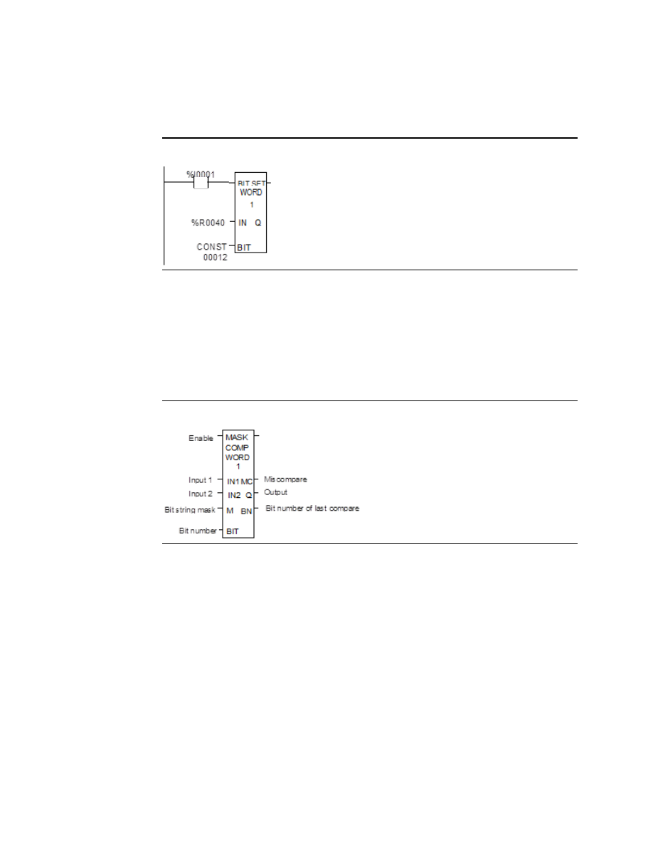
In the example, whenever input %I0001 is set, bit 12 of the string beginning at reference 
%R0040 is set to 1. 

Figure 253 


23.1.9


Bit Operation Functions 
Masked Compare 

The  Masked  Compare  function  compares  the  contents  of  two  separate  bit  strings.  It 
provides the ability to mask selected bits.  Input string 1 might contain the states of outputs 
such as solenoids or motor starters. Input string 2 might contain their input state feedback, 
such as limit switches or contacts. 

Figure 254 


When the function receives power flow, it begins comparing the bits in the first string with 
the corresponding bits in the second string. Comparison continues until a miss-compare is 
found or until the end of the string is reached. 

The BIT input stores the bit number where the next comparison should start (a 0 indicates 
the first bit in the string). The BN output stores the bit number where the last comparison 
occurred (where a 1 indicates the first bit in the string).  Using the same reference for BIT 
and BN causes the compare to start at the next bit position after a miss-compare; or, if all 
bits compared  successfully upon the  next invocation of the function block, the compare 
starts at the beginning. 

To start the next comparison at some other location in the string, you can enter different 
references for BIT and BN. If the value of BIT is a location that is beyond the end of the string, 
BIT is reset to 0 before starting the next comparison.


User Manual 

Chapter 23 

GFK-1645M 

Dec 2019 


Instruction Set Reference 

435 

Parameters of the Masked Compare Function 

Input/ 
Output 

Choices 

Description 

enable 

flow 

Permissive logic to enable the function.  

IN1 

R, AI, AQ 
For WORD only: I, Q, M, T, S, G 

Reference for the first bit string to be compared.  

IN2 

R, AI, AQ 
For WORD only: I, Q, M, T, S, G 

Reference for the second bit string to be compared.  

R, AI, AQ 
For WORD only: I, Q, M, T, SS, 
SB, SC, G 

Reference for the bit string mask.  

BIT 

I, Q, M, T, S, G, R, AI, AQ, 
constant 

Reference for the bit number where the next 
comparison should start.  

MC 

flow, none 

User logic to determine if a miscompare has occurred. 

R, AI, AQ 
For WORD only: I, Q, M, T, SA, 
SB, SC, G 

Output copy of the mask (M) bit string.  

BN 

I, Q, M, T, S, G, R, AI,  AQ 

Bit number where the last miscompare occurred.  

length 

Constant 

The number of words in the bit string. Max. is 4095 for 
WORD and 2047 for DWORD. 

Operation of the Masked Compare  

If 

all corresponding bits in strings IN1 and IN2 match, the function sets the “miss

-

compare” 

output MC to 0 and BN to the highest bit number in the input strings.  The comparison then 
stops.  On the next invocation of a Masked Compare Word, it is reset to 0. When the two bits 
currently  being  compared  are  not  the  same,  the  function  checks  the  correspondingly 
numbered bit in string M (the mask).  If the mask bit is a 1, the comparison continues until 
it  reaches  another  miss-compare  or  the  end  of  the  input  strings.  If  a  miss-compare  is 
detected and the corresponding mask bit is a 0, the function does the following: 

1.


Sets the corresponding mask bit in M to 1. 

2.


Sets the miss-compare (MC) output to 1. 

3.


Updates the output bit string Q to match the new content of mask string M 

4.


Sets the bit number output (BN) to the number of the miss-compared bit.  

5.


Stops the comparison.  

Example 

In the example, after first scan the Masked Compare Word function executes. It compares 
%M0001

16  with  %M0017

32.    %M0033

48  contains  the  mask.    The  value  in  %R0001 

determines the bit position in the two input strings where the comparison starts.


User Manual 

Chapter 23 

GFK-1645M 

Dec 2019 


Instruction Set Reference 

436 

Figure 255 


Before the function block is executed, the contents of the above references are: 

Figure 256 


The contents of these references after the function block executes are: 

Figure 257 


In this example, contact %T1 and coil %M100 force one and only one execution; otherwise 
the function would repeat with possibly unexpected results. 

23.1.10


Bit Operation Functions 
Bit Position 

The Bit Position function locates a bit set to 1 in a bit string. 

Each sweep that power is received, the function scans the bit string starting at IN.  When 
the function stops scanning, either a bit equal to 1 has been found or the entire length of 
the string has been scanned. 

POS is set to the position within the bit string of the first non-zero bit; POS is set to zero if 
no non-zero bit is found. 

A string length of 1 to 256 words can be selected.  The function passes power flow to the 
right whenever enable is ON.


User Manual 

Chapter 23 

GFK-1645M 

Dec 2019 


Instruction Set Reference 

437 

Figure 258 


Parameters for the Bit Position Function 

Input/ 
Output 

Choices 

Description 

enable 

flow 

When the function is enabled, a bit search operation is 
performed. 

IN 

I, Q, M, T, S, G, R, AI, AQ 

IN contains the first word of the data to be operated on. 

ok 

flow, none 

The OK output is energized whenever enable is energized. 

POS 

I, Q, M, T, G, R, AI, AQ 

The position of the first non-zero bit found, or zero if a 
non-zero bit is not found. 

Example 

In the example, if %I0001 is set, the bit string starting at %M0001 is searched until a bit equal 
to 1 is found.  Coil %Q0001 is turned on.  If a bit equal to 1 is found, its location within the bit 
string is written to %AQ001.  If %I0001 is set, bit %M0001 is 0, and bit %M0002 is 1, then the 
value written to %AQ001 is 2 

Figure 259 


User Manual 

Chapter 23 

GFK-1645M 

Dec 2019 


Instruction Set Reference 

438 

23.1.11


Bit Operation Functions 
Bit Sequencer 

The Bit Sequencer function performs a bit sequence shift through an array of bits. 

Figure 260 


The operation of the function depends on the previous value of the parameter EN: 

R Current 
Execution 

EN Previous 
Execution 

EN Current 
Execution 

 
Bit Sequencer Execution 

OFF 

OFF 

OFF 

Bit sequencer does not execute. 

OFF 

OFF 

ON 

Bit sequencer increments/decrements 
by 1. 

OFF 

ON 

OFF 

Bit sequencer does not execute. 

OFF 

ON 

ON 

Bit sequencer does not execute. 

ON 

ON/OFF 

ON/OFF 

Bit sequencer resets. 

The reset input (R) overrides the enable (EN) and always resets the sequencer. When R is 
active, the current step number is set to the value passed in via the step number parameter.  
If no step number is passed in, step is set to 1.  All of the bits in the sequencer are set to 0, 
except for the bit pointed to by the current step, which is set to 1.  

When Enable is active and Reset is not active, the bit pointed to by the current step number 
is cleared.  The current step number is incremented or decremented, based on the direction 
parameter.  Then, the bit pointed to by the new step number is set to 1.  

The  parameter  ST  is  optional.    If  it  is  not  used,  the  Bit  Sequencer  function  operates  as 
described above, except that no bits are set or cleared.  The function just cycles the current 
step number through its legal range.  

Memory Required for a Bit Sequencer 

Each bit sequencer uses three words (registers) of %R memory to store the information:  

word 1 

current step number 

word 2 

length of sequence (in bits) 

word 3 

control word 

Word  3  (the  control  word)  stores  the  state  of  the  Boolean  inputs  and  outputs  of  its 
associated function block, in the following format:  

User Manual 

Chapter 23 

GFK-1645M 

Dec 2019 


Instruction Set Reference 

439 

Figure 261 


Parameters for the Bit Sequencer Function 

Input/ 
Output 

Choices 

Description 

address  R 

Address is the location of the bit sequencer’s current step, 

length, and the last enable and OK status. 

enable 

flow 

When the function is enabled, if it was not enabled on the 
previous sweep and if R is not energized, the bit sequence 
shift is performed.  

flow 

When R is energized, the bit sequencer’s step number is set 

to the value in STEP (default = 1),   and the bit sequencer is 
filled with zeros, except for the current step number bit. 

DIR 

flow 

When DIR is energized, the bit sequencer’s step number is 

incremented prior to the shift.  Otherwise, it is 
decremented.  

STEP 

I, Q, M, T, G, R, AI, AQ, 
constant, none 

When R is energized, the step number is set to this value.  

ST 

I, Q, M, T, SA, SB, SC, G, R, 
AI, AQ, none 

ST contains the first word of the bit sequencer. Optional. 

ok 

flow, none 

The OK output is energized whenever the function is 
enabled. 

Example 

In the example, the Bit Sequencer operates on register memory %R0001.  Its static data is 
stored in registers %R0010

12.  When CLEAR is active, the sequencer is reset and the current 

step is set to step number 3.  The first 8 bits of %R0001 are set to zero.  

When NXT_CYC is active and CLEAR is not active, the bit for step number 3 is cleared and 
the bit for step number 2 or 4 (depending on whether DIR is energized) is set. 

Figure 262 


User Manual 

Chapter 23 

GFK-1645M 

Dec 2019 


Instruction Set Reference 

440 

23.2


Control Functions 

This section describes the control functions, which may be used to limit program execution 
and to change the way the CPU executes the application program. 


Service specified I/O: DO IO 


Go to a subroutine block: CALL 


Temporary program end: END 


Execute a group of logic rungs without power flow: MCR 


Go to a specified location in the program: JUMP, LABEL 


Place a text explanation in the program logic: COMMENT 


Provide predefined On/Off patterns to a set of 16 discrete outputs in the manner of 
a mechanical DRUM SEQUENCER. 

The  more  complex  Control  Functions;  Service  Request  and  the  PID  algorithms,  are 
described in other chapters of this manual. 

23.2.1


Control Functions 
Do I/O 

The Do I/O function updates inputs or outputs for one scan while the program is running.  
The Do I/O function can also be used to update selected I/O during the program in addition 
to the normal I/O scan. 

Figure 263 


Execution of the function continues until all inputs in the selected range have reported or all 
outputs have been serviced.  Program execution then returns to the next function.  

The function passes power to the right whenever power is received, unless:  


Not all references of the type specified are present within the selected range.  


The Micro PLC is not able to properly handle the temporary list of I/O created by the 
function.  


The range specified includes modules associated with a “Loss of I/O" fault.


User Manual 

Chapter 23 

GFK-1645M 

Dec 2019 


Instruction Set Reference 

441 

Using DO I/O with Expansion Units 

The  Do  I/O  function  always  correctly  updates  the  reference  addresses  of  the  I/O  being 
scanned, even if some I/O addresses have been skipped in auto-configuring the PLC. If a 14-
point  Micro  PLC  with  attached  expansion  I/O  is  auto-configured,  I/O  addresses  I0009 
through I0016 and  Q0009 through Q0016 are skipped  and the I/O addresses of the first 
expansion  unit  will  start  at  I0017  and  Q0017.  The  Do  I/O  function  updates  these  I/O 
correctly, without reserving the skipped memory areas. The reference memory at the Do 
I/O ALT parameter contains 16 points of data: 8 points for the module and 8 points for the 
expansion unit.  

Note: 

Using DO_IO with the ALT parameter to expansion modules IC200UDD06, UEC208, UEI016, 
UEO008, and UER016 is not supported. 

Parameters of the Do I/O Function 

Input/
Output 

Choices 

Description 

enable 

flow 

When the function is enabled, a limited input or output scan is 
performed. 

ST 

I, Q, AI, AQ 

The starting address of the I/O to be serviced. 

END 

I, Q, AI, AQ 

The ending address of the I/O to be serviced. 

ALT 

I, Q, M, T, G, R, 
AI, AQ, none 

For the input scan, ALT specifies the address to store scanned input 
point/word values.  For the output scan, ALT specifies the address to 
get output point/word values from.  If a constant value is specified for 
ALT, it is ignored. 

ok 

flow, none 

OK is energized when the scan completes normally.  

Do I/O for Inputs 

If input references are specified, when the function receives power flow, the PLC scans input 
points from the starting reference (ST) to the END reference.  If a reference is specified for 
ALT, copies of the new input values are placed in memory beginning at that reference, and 
the real input values are  not updated.  ALT must be the same  size as the reference type 
scanned.  If a discrete reference is used for ST and END, ALT must also be discrete. 

If no reference is specified for ALT, the real input values are updated.  This allows inputs to 
be scanned one or more times during the program execution portion of the CPU sweep. 


User Manual 

Chapter 23 

GFK-1645M 

Dec 2019 


Instruction Set Reference 

442 

Example Do I/O for Inputs:  

In this example, when the function receives power flow, the PLC scans references %I0001-
64 and %Q0001 is turned on.  Copies of the scanned inputs are placed in internal memory 
from %M0001-64.  Because a reference is specified for ALT, the real inputs are not updated.  
This allows the current values of inputs to be compared with their values at the beginning of 
the scan. 

Figure 264 


Do I/O for Outputs 

If output references are specified, when the function receives power flow, the PLC writes the 
latest output values from the starting reference (ST) to the END reference to the output 
points.  If outputs should be written to the output points from internal memory other than 
%Q or %AQ, the beginning reference can be specified for ALT. 

Example Do I/O For Outputs:  

In the  next example, when  the function receives power flow, the  PLC writes values from 
references %R0001-0004 to analog output channels %AQ001-004 and %Q0001 is turned on.  
Because a reference is entered for ALT, the values at %AQ001-004 are not written to. 

Figure 265 


If no reference were specified for ALT, the PLC would write values at references %AQ001-
004 to analog output channels. 


User Manual 

Chapter 23 

GFK-1645M 

Dec 2019 


Instruction Set Reference 

443 

23.2.2


Control Functions 
Call 

The Call function causes program execution to go to a specified subroutine block. 

Figure 266 


When the Call function receives power flow, it causes the scan to go immediately to the 
designated subroutine block and execute it.  After the subroutine block execution is 
complete, control returns to the point in the logic immediately following the Call 
instruction.  

Example 

Figure 267 


23.2.3


Control Functions 
End of Logic 

The End of Logic function provides a temporary end of logic.  The program executes from 
the first rung to the last rung or the End of Logic function, whichever is encountered first. 

The  End  of  Logic  function  unconditionally  terminates  program  execution.    There  can  be 
nothing after the end function in the rung.  No logic beyond the End of Logic function is 
executed, and control is transferred to the beginning of the program for the next sweep. 

The End of Logic function is useful for debugging purposes because it prevents any logic 
which follows from being executed. 

The programming software provides an [ END OF PROGRAM LOGIC ] marker to indicate the 
end of program execution.  This marker is used if no End of Logic function is programmed in 
the logic. 

Figure 268 


User Manual 

Chapter 23 

GFK-1645M 

Dec 2019 


Instruction Set Reference 

444 

Example 

In the example, an End of Logic function is programmed to terminate the end of the current 
sweep. 

Figure 269 


23.2.4


Control Functions 
Master Control Relay (MCR) / End MCR 

All rungs between an active Master Control Relay (MCRN) and its corresponding End Master 
Control  Relay  (ENDMCRN)  function  are  executed  without  power  flow  to  coils.    The 
ENDMCRN  associated  with  the  Master  Control  Relay  is  used  to  resume  normal  program 
execution.    Unlike  Jump  functions,  Master  Control  Relays  can  only  move  forward;  the 
ENDMCRN  must  appear  after  its  corresponding  Master  Control  Relay  instruction  in  a 
program. 

Nested MCR 

A  Nested  Master  Control  Relay  function  can  be  nested  completely  within  another 
MCRN/ENDMCRN pair. 

There can be multiple Master Control Relay functions with a single ENDMCRN. 

The Master Control Relay function has an enable input and a name.  This name is used again 
with the ENDMCRN.  The Master Control Relay has no outputs; there can be nothing after it 
in a rung. 

Figure 270 


With a Master Control Relay, function blocks within the scope of the Master Control Relay 
are executed without power flow, and coils are turned off.   

The ENDMCRN function must be tied to power rail; there can be no logic before it in the 
rung.  The  name  of  the  ENDMCRN  associates  it  with  the  corresponding  Master  Control 
Relay(s). The ENDMCRN function has no outputs; there can be nothing after it in a rung. 

Figure 271 


User Manual 

Chapter 23 

GFK-1645M 

Dec 2019 


Instruction Set Reference 

445 

Example Master Control Relay and ENDMCRN Functions 

In the example, when %I0002 is ON, the Master Control Relay is enabled. When the Master 
Control  Relay  is  enabled--even  if  %I0001  is  ON--the  Addition  function  block  is  executed 
without power flow (i.e., it does not add 1 to %R0001), and %Q0001 is turned OFF. 

If %I0003 and %I0004 are ON, %Q0003 is turned OFF and %Q0004 remains ON. 

Figure 272 


23.2.5


Control Functions 
Jump, Label 

The Nested Jump instruction causes a portion of the program logic to be bypassed.  Program 
execution continues at the Label specified. When the Jump is active, all coils within its scope 
are left at their previous states. This includes coils associated with timers, counters, latches, 
and relays. 

The Nested Jump instruction has the form ----->>LABEL01, where LABEL01 is the name of the 
corresponding nested Label instruction. 

A nested Jump can be placed anywhere in a program. 

There  can  be  multiple  nested  Jump  instructions  corresponding  to  a  single  nested  Label.  
Nested Jumps can be either forward or backward Jumps. 

There can be nothing after the Jump instruction in the rung.  Power flow jumps directly from 
the instruction to the rung with the named label. 

CAUTION 

To avoid creating an endless loop with forward and backward Jump instructions, a backward 
Jump must contain a way to make it conditional. 


User Manual 

Chapter 23 

GFK-1645M 

Dec 2019 


Instruction Set Reference 

446 

Label 

The Label instruction is the target of a Jump.  Use the Label instruction to resume normal 
program execution. There can be only one Label with a particular name in a program.  

The Label instruction has no inputs and no outputs; there can be nothing either before or 
after a Label in a rung.  

Example Jump and Label Instructions 

In the example, whenever Jump TEST1 is active, power flow is transferred to Label TEST1.  

With a Jump, any function blocks between the Jump and the Label are not executed, and 
coils are not affected.  In the example, when %I0002 is ON, the Jump is taken.  Since the logic 
between the Jump and the Label is skipped, %Q0001 is unaffected (if it was ON, it remains 
ON; if it was OFF, it remains OFF). 

Figure 273 


23.2.6


Control Functions 
Comment 

The Comment function is used to enter a comment (rung explanation) in the program.  A 
comment can have up to 2048 characters of text. Longer text can be included in printouts 
using an annotation text file. 

It is represented in the ladder logic like this:  

Figure 274 


User Manual 

Chapter 23 

GFK-1645M 

Dec 2019 


Instruction Set Reference 

447 

23.2.7


Control Functions 
Drum Sequencer 

The Drum Sequencer function is a program instruction that operates like a mechanical drum 
sequencer. The Drum Sequencer steps through a set of potential output bit patterns and 
selects one based on inputs to the function block. The selected value is copied to a group of 
16 discrete output references. 

Figure 275 


Power flow to the Enable input causes the Drum Sequencer to copy the content of a selected 
reference to the Out reference. 

Power flow to the Reset input or to the Step input selects the reference to be copied. 

The  Control  Block  input  is  the  beginning  reference  for  the  Drum  Sequencer  function’s 

parameter block, which includes information used by the function. 

Parameters of the Drum Sequencer Function 

Input/
Output 

Choices 

Description 

enable 

flow 

The Enable input controls execution of the function.  

Step 

flow 

The Step input can be used to go one step forward in the sequence. 
When the Enable input receives power flow and the Step input makes 
an Off to  on  transition, the  Drum  Sequencer moves  one step. When 
Reset is active, the function ignores the Step input. 

Reset 

flow 

The Reset input can be used to select a specific step in the sequence. 
When Enable and Reset both receive power flow, the function copies 
the Preset Step value in the Control Block to the active Step reference, 
also in the Control Block.  Then the function block copies the value in 
the  Preset  Step  reference  to  the  Out-reference  bits.  When  Reset  is 
active, the function ignores the Step input. 

Pattern  R, AI, AQ 

The starting address of an array of words, each representing one step 
of the Drum Sequencer. The value of each word represents the desired 
combination  of  outputs  for  a  particular  value  of  Active  Step.  The 
number of elements in the array is equal to the length input. 

User Manual 

Chapter 23 

GFK-1645M 

Dec 2019 


Instruction Set Reference 

448 

Input/
Output 

Choices 

Description 

Dwell 
Time 

R, AI, AQ, none 

This optional input array of words has one element for each element in 
the Pattern array. Each value in the array represents the dwell time for 
the  corresponding  step  of  the  Drum  Sequencer  in  0.1  second  units. 
When the dwell time expires for a given step the Dwell Timeout bit is 
set. 
If a Dwell Time is specified, the drum cannot sequence into its next step 
until the Dwell Time has expired. 

Fault 
Timeout 

R, AI, AQ, none 

This optional input array of words has one element for each element in 
the Pattern array. Each value in the array represents the fault timeout 
for the corresponding step of the Drum Sequencer in 0.1 second units.  
When the fault timeout has expired the Fault Timeout bit is set. 

Control 
Block 

The  beginning  reference  address  of  the 

function’s  parameter  block. 

The  length  of  the  Control  Block  is  5  words.  A  more  complete 
description of what is contained within this block is listed below. 

Length  CONST 

Value between 1 and 128 that specifies the number of steps. 

ok 

flow, none 

OK is energized if Enable is On and no error  condition  is detected. If 
Enable is Off, this output will always be Off. 

OUT 

I, Q, M, T, G, R, 
AI, AQ 

A word of memory containing the  element of the Pattern  Array  that 
corresponds to the current Active Step. 

Drum 
Coil 

I, Q, M, T, G, 
none 

This  optional  bit  reference  is  set  whenever  the  function  block  is 
enabled, and Active Step is not equal to Preset Step. 

Dwell 
Timeout 

I, Q, M, T, G, 
none 

This optional bit reference is set if the dwell time for the current step 
has expired. 

Timeout 
Fault 

I, Q, M, T, G, 
none 

This optional bit reference is set if the drum has been in a particular step 

longer than the step’s specified Fault Timeout.


First 
Follower 

I, Q, M, T, G, 
none 

This optional array of bits has one element for each step of the Drum 
Sequencer. No more than one bit in the array is On at any time and that 
bit corresponds to the value of the Active Step 

Parameter Block for the Drum Sequencer Function 

The parameter block (control block) for the Drum Sequencer function contains 
information needed to operate the Drum Sequencer. 

address 

Active Step 

address + 1 

Preset Step  

address + 2 

Step Control 

address + 3  

Timer Control 

Active Step 

The active step value specifies the element in the Pattern array to copy to 

the Out output memory location. This is used as the array index into the Pattern, Dwell 
Time, Fault Timeout, and First Follower arrays. 

Preset Step 

A word input that is copied to the Active Step output when the Reset is On. 

User Manual 

Chapter 23 

GFK-1645M 

Dec 2019 


Instruction Set Reference 

449 

Step Control  A word that is used to detect Off to On transitions on both the Step input and 
the Enable input. The Step Control word is reserved for use by the function block, and must 
not be written to. 

Timer Control  Two words of data that hold values needed to run the timer. These values are 
reserved for use by the function block and must not be written to. 

Notes on Using the Drum Sequencer Function 

1.


The Dwell Timeout Output bit is cleared the first time the drum is in a new step. This 
is true: 


Whether the drum is introduced to a new step by changing the Active Step or 
by using the Step Input. 


Regardless  of  the  Dwell  Time  Array  value  associated  with  the  step  
(even if it is 0). 


During the first sweep the Active Step is initialized. 

2.


The Active and Preset Step of the Drum Sequencer’s control block must be initializ

ed 

for the Drum Sequencer to work or to pass power flow. Even if the Active Step is in 
the correct range (between 1 and length of the Pattern array) and the Preset Step is 
not used, the drum will not function if the Preset Step is not in the proper range. 

23.3


Data Move Functions 

The Data Move functions of the Instruction Set provide basic data move capabilities. 


MOVE Data. This function copies data as individual bits, so the new location does not 
have to be the same data type.  


Block Move. This function places constants into seven specified memory locations.  


Block Clear. This function fills an area of memory with zeros.  


Shift  Register.  This  function  shifts  one  or  more  data  words  or  data  bits  from  a 
reference location into a specified area of memory. Data already in the area is shifted 
out. 


Communication Request (COMMREQ). This important function allows the CPU to 
communicate with intelligent modules in the system, for example, communications 
modules. The basic format of the COMMREQ function is shown in this chapter. The 
detailed  parameters  needed  to  program  specific  communications  tasks  are 
provided in the documentation for each module. 


Content      ..     28      29      30      31     ..