EMERSON PACSystems VersaMax MICRO PLC & NANO PLC. USER MANUAL (2019) - page 28
 

  Index      Manuals     EMERSON PACSystems VersaMax MICRO PLC & NANO PLC. USER MANUAL (2019)


Search            copyright infringement  


Content      ..     26      27      28      29     ..


EMERSON PACSystems VersaMax MICRO PLC & NANO PLC. USER MANUAL (2019) - page 28


User Manual 

Chapter 21 

GFK-1645M 

Dec 2019 


Elements of an Application Program 

402 

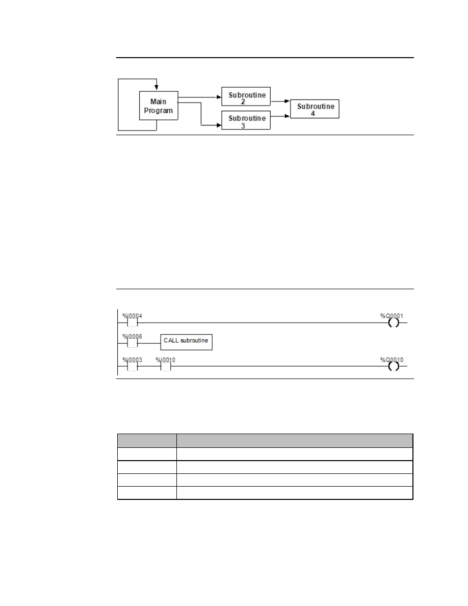
Figure 233 


The main program is level 1. The program can include up to eight additional nested call 
levels. 

21.2.1


Declaring a Subroutine 

A subroutine must be declared through the block declaration editor of the programming 
software. 

21.2.2


Calling a Subroutine 

A subroutine invoked in the program is using a CALL instruction. Up to 64 subroutine block 
declarations are allowed for Micro CPUs.  Up to 8 subroutine block declarations are allowed 
for NANO CPUs.  Regardless of the CPU model, 64 CALL instructions are allowed for each 
block in the program. 

Figure 234 


21.2.3


Locking/Unlocking Subroutines 

Subroutine blocks can be locked and unlocked from the programming software.  There are 
four levels of locking:  

Type of Lock 

Description 

View 

When locked, the subroutine cannot be viewed. 

Edit 

When locked, the information in the subroutine cannot be changed. 

Perm View 

The subroutine is permanently locked and cannot be unlocked.  

Perm Edit 

The subroutine is permanently locked and cannot be unlocked.  

Permanently locked subroutines cannot be unlocked, even if the program is copied, backed 
up, or restored. A previously view-locked or edit-locked subroutine can be unlocked. 


User Manual 

Chapter 21 

GFK-1645M 

Dec 2019 


Elements of an Application Program 

403 

21.3


Program Languages 

Application programs for VersaMax Nano PLCs and Micro PLCs can be created in Ladder 
Diagram or Instruction List format.  

21.3.1


Ladder Diagram 

This traditional PLC programming language, with its rung-like structure, executes from top 

to bottom. The logic execution is thought of as “power flow”, which proceeds down along 
the left “rail” of the ladder, and from left to right along each rung

 in sequence. 

Figure 235 


The  flow  of  logical  power  through  each  rung  is  controlled  by  a  set  of  simple  program 
functions that work like mechanical relays and output coils. Whether or not a relay passes 
logical power flow along the rung depends on the content of a memory location with which 
the relay has been associated in the program. For instance, a relay might pass power flow if 
its associated memory location contained the value 1. The same relay would not pass power 
flow if the memory location contained the value 0. 

If a relay or other function in a rung does not pass logical power flow, the rest of that rung is 
not executed. Power then flows down along the left rail to the next rung. 

A rung contains complex functions that can be used for operations like moving data stored 
in  memory,  performing  math  operations,  and  controlling  communications  between  the 
Micro PLC and other devices in the system. 

Some program functions, such as the Jump function and Master Control Relay, can be used 
to control the execution of the program itself. 

Together,  this  large  group  of  Ladder  Diagram  relays,  coils,  and  functions  is  called  the 

“Instruction Set” of the Micro PLC.


21.4


The Instruction Set 

A  VersaMax  Nano  PLC  or  Micro  PLC  provides  a  powerful  Instruction  Set  for  building 
application programs.  

As a guide to the programming capabilities of the VersaMax Micro PLC, all of the relays, coils, 
functions,  and  other  elements  of  the  Instruction  Set  are  listed  on  the  following  pages. 
Complete reference information is included in Chapter 23: and in the online help for the 
programming software.


User Manual 

Chapter 21 

GFK-1645M 

Dec 2019 


Elements of an Application Program 

404 

21.4.1


Contacts 

| |

  Normally Open  

Passes power if the associated reference is ON. 

|/|

  Normally Closed   Passes power if the associated reference is OFF. 

|+|

  Continuation  

Passes power to the right if the preceding continuation coil is set ON. 

21.4.2


Coils 

( )


Normally Open  Sets the associated reference ON if the coil receives power. Otherwise 

OFF. 

(/)


Negated  

Sets the associated discrete reference ON if the coil does not receive 
power. Otherwise OFF. 

( )


Positive 
Transition 

If power flow was OFF to this coil the last time it was executed and is 
ON this time, then the coil is turned ON. Otherwise, the coil is turned 
OFF.  

( )


Negative 
Transition  

If power flow was ON to this coil the last time it was executed and is 
OFF this time, then the coil is turned ON. Otherwise, the coil is turned 
OFF.  

(S)


SET  

Sets the associated discrete reference ON if the coil receives power. It 
remains set until reset by an 

(R)

 coil. 

(R)


RESET  

Sets the associated discrete reference OFF if the coil receives power.  It 
remains reset until set by an 

(S)

 coil. 

(SM)

  Retentive SET  

Sets the associated reference ON if the coil receives power.  The 
reference remains set until reset by an 

(RM)

 coil.  Its state is retained 

through power failure and STOP-TO-RUN transition. 

(RM)

  Retentive 

RESET  

Resets the associated discrete reference OFF if the coil receives power. 
The reference remains reset until set by an 

(SM)

 coil. Its state is 

retained through power failure and STOP-TO-RUN transition. 

(/M)

  Negated 

Retentive  

Sets the associated discrete reference ON if the coil does not receive 
power.  The state is retained through power failure and STOP-TO-RUN 
transition. Otherwise OFF. 

(M)


Retentive  

Sets the associated discrete reference ON if the coil receives power.  
The state is retained through power failure and STOP-TO-RUN 
transition. Otherwise OFF. 

 (+)


Continuation  

If power to the coil is ON, the continuation coil sets the next 
continuation contact ON.  If power is OFF, the continuation coil sets the 
next continuation contact OFF. 


User Manual 

Chapter 21 

GFK-1645M 

Dec 2019 


Elements of an Application Program 

405 

21.4.3


Timers and Counters 

ONDTR  On-Delay 

Stopwatch Timer 

Accumulates time while receiving power. The current value is reset 
to zero when the reset input receives power. 

OFDT 

Off-Delay Timer 

Accumulates time while NOT receiving power. The current value is 
reset to zero when there is power flow. 

TMR 

On-Delay Timer 

Accumulates time while receiving power. The current value is reset 
to zero when there is no power flow. 

UPCTR  Up Counter 

Increments by 1 each time the function receives transitional power.   

DNCTR  Down Counter 

Counts down from a preset value every time the function receives 
transitional power.  

21.4.4


Math Functions 

ADD 

Addition 

Adds two numbers.  

SUB 

Subtraction 

Subtracts one number from another. 

MUL 

Multiplication 

Multiplies two numbers.  

DIV 

Division 

Divides one number by another, yielding a quotient.   

MOD 

Modulo Division 

Divides one number by another, yielding a remainder.   

EXPT 

Power of X 

Raises X to the power specified by IN and places the result in Q. 

SIN 

Sine 

Finds the trigonometric sine of a real number.  

COS 

Cosine 

Finds the trigonometric cosine of a real number.  

TAN 

Tangent 

Finds the trigonometric tangent of a real number.  

ASIN 

Inverse Sine 

Finds the inverse sine of a real number.  

ACOS 

Inverse Cosine 

Finds the inverse cosine of a real number.  

ATAN 

Inverse Tangent 

Finds the inverse tangent of a real number.  

DEG 

Convert to Degrees  Performs a RAD_TO_DEG conversion on a real radian value.  

RAD 

Convert to Radians  Performs a DEG_TO_RAD conversion on a real degree value.  

SCALE  Scaling 

Scales an input constant or word value. 

SQRT 

Square Root 

Finds the square root of an integer or real value. 

LOG 

Base 10 Logarithm  Finds the base 10 logarithm of a real value.  

LN 

Natural Logarithm  Finds the natural logarithm base of a real number.  

EXP 

Power of e 

Raises the natural logarithm base to the power specified by input.  


User Manual 

Chapter 21 

GFK-1645M 

Dec 2019 


Elements of an Application Program 

406 

21.4.5


Relational Functions 

EQ 

Equal 

Tests for equality between two numbers.   

NE 

Not Equal 

Tests for non-equality between two numbers.  

GT 

Greater Than 

Tests whether one number is greater than another.  

GE 

Greater Than or Equal 
To 

Tests whether one number is greater than or equal to another 

LT 

Less Than 

Tests whether one number is less than another.  

LE 

Less Than or Equal To 

Tests whether one number is greater than or equal to another. 

RANGE  Range 

Test the input value against a range of two numbers.   

21.4.6


Bit Operation Functions 

AND 

Logical AND 

Performs Logical AND of two bit strings.   

OR 

Logical OR 

Performs Logical OR of two bit strings. 

XOR 

Logical Exclusive OR  Performs Logical Exclusive OR of two bit strings. 

NOT 

Logical Invert 

Performs a logical inversion of a bit string.   

SHL 

Shift Left 

Shifts a bit string left. 

SHR 

Shift Right 

Shifts a bit string right. 

ROL 

Rotate Left 

Rotates a bit string left. 

ROR 

Rotate Right 

Rotates a bit string right.   

BIT_TEST 

Bit Test 

Test a bit within a bit string to determine whether that bit is 
currently 1 or 0. 

BIT_SET 

Bit Set 

Sets one bit within a string to true. 

BIT_CLR 

Bit Clear 

Sets one bit within a string to false. 

BIT_POS 

Bit Position 

Locates a bit set to true within a bit string. 

MASK_COMP  Masked Compare 

Performs a masked compare of two arrays. 

21.4.7


Data Move Functions 

MOVE 

Move 

Moves one or more bits of data. 

BLKMOV 

Block Move 

Moves a block of up to 7 constants. 

BLK_CLR 

Block Clear 

Clears to zero one or more bytes/words of memory. 

SHFR 

Shift Register 

Shifts one or more words or bits of data through a block 
of memory. 

BIT_SEQ 

Bit Sequencer 

Sequences a 1 through a group of bits in PLC memory.  

COMMREQ 

Communication 
Request 

Sends a communications request. 


User Manual 

Chapter 21 

GFK-1645M 

Dec 2019 


Elements of an Application Program 

407 

21.4.8


Table Functions 

ARRAY_MOVE  Array Move 

Copies a specified number of data elements from a 
source array to a destination array. 

SEARCH_EQ 

Search Equal 

Searches array for values equal to a specified value. 

SEARCH_NE 

Search Not Equal 

Searches array for values not equal to a specified value. 

SEARCH_GT 

Search Greater Than 

Searches array for values greater than a specified value. 

SEARCH_GE 

Search Greater Than or 
Equal 

Searches array for values greater than or equal to a 
specified value. 

SEARCH_LT 

Search Less Than 

Searches array for values less than a specified value. 

SEARCH_LE 

Search Less Than or 
Equal 

Searches array for values less than or equal to a 
specified value. 

21.4.9


Conversion Functions 

INT_TO_BCD4 

Convert to BCD-4 (From INT) 

Converts a number to 4-digit BCD format.   

REAL_TO_WORD  Convert to Word (From REAL)  Converts a Real value to Word format.   

BCD4_TO_INT 
BCD4_TO_REAL 

Convert to INT (From BCD-4 or 
REAL) 

Converts a number to signed integer format.   

BCD4_TO_DINT 
REAL_TO_DINT 

Convert to DINT 
(From BCD-4 or REAL) 

Converts a number to double precision integer 
format.   

INT_TO_REAL 
DINT_TO_REAL 
BDC4_TO_REAL 
WORD_TO_REAL 

Convert to Real 
(From INT, DINT, BCD-4 or 
WORD) 

Converts a value to real value format.   

REAL_TO_INT 

Truncate to INT (from REAL) 

Truncates to a 16-bit signed number.  The 
range is 

32,768 to +32,767.  

REAL_TO_INT 

Truncate to Double Precision 
INT (from REAL) 

Truncates to a 32-bit signed number.  The 
range is -2,147,483,648 to +2,147,483,647.  

21.4.10


Control Functions 

CALL 

Call 

Causes a program execution to go to a specified 
subroutine block. 

DO_IO 

Do I/O 

Services a specified range of inputs or outputs 
immediately (all inputs or outputs on a module will be 
serviced if any addresses on that module are included 
in the function 

 partial I/O module updates are not 

performed 

PID_IND 

Independent PID Algorithm  Selects the non-interacting independent PID algorithm. 

PID_ISA 

ISA PID Algorithm 

Selects the ISA PID algorithm. 

END 

Temporary End of Logic 

The program executes from the first rung to the last 
rung or the END instruction, whichever is encountered 
first.  This instruction is useful for debugging purposes. 

COMMENT  Comment 

A rung explanation.   

User Manual 

Chapter 21 

GFK-1645M 

Dec 2019 


Elements of an Application Program 

408 

SVCREQ 

Service Request 

A special PLC service function. 

MCRN 

Master Control Relay 

Starts a master control relay range.  An MCR causes all 
rungs between the MCR and its subsequent ENDMCR to 
be executed with no power flow. Up to 8 MCRs can be 
nested. 

ENDMCR 

End Master Control Relay 

Ends a master control relay range.   

JUMP 

Jump 

Jumps to a specified location indicated by a LABEL in 
the logic. 

LABEL 

Label 

The target location of a JUMP instruction. Multiple 
Jump instructions can reference the same label. 

DRUM 

Drum Sequencer 

Operates like a mechanical drum sequencer, selecting a 
16-bit output pattern from an array of stored patterns, 
and sending it to a set of outputs. 

21.4.11


Communication Function 

MODBUS_TCP_RW  MODBUS/TCP 

read/write 

Processes read and write requests for MODBUS/TCP 
Client support 

21.4.12


Motion Functions 

FIND_HOME 

Find Home 

Defines a Home (zero) position for an axis. 

GO_HOME 

Go Home 

Moves the motor to a position that has been 
defined by the Find Home function. 

JOGGING 

Jogging 

Jogs the axis backward or forward at the specified 
acceleration and velocity. 

BLENDING 

Blending 

Executes up to four successive moves without the 
distance and velocity output values retuning to zero 
between moves. 

STOP_MOTION 

Stop Motion 

Stops all motion on the channel while leaving the 
channel active. 


User Manual 

Chapter 22 

GFK-1645M 

Dec 2019 


Program Data and References 

409 

Chapter 22:


Program Data and References 

This chapter describes the types of data that can be used in an application program, and 
explains how that data is stored in memory by a VersaMax Nano PLC or VersaMax Micro PLC. 


Data memory references 


Fixed I/O map locations 


Retentiveness of data 


System status references 


Time tick contacts 


How program functions handle numerical data 

22.1


Data Memory References 

Data in PLC programs is referenced by memory addresses that specify both a memory type 
and a precise address within that memory type. For example:  

%I00001 

specifies address 1 in Input memory. 

%R00256 

specifies address 256 in Register memory. 

The letter prefix indicates where data is stored in PLC memory.  

22.1.1


Memory Allocation 

The following table shows the types and sizes of available memory in VersaMax Micro and 
Nano PLCs. (See Appendix B: for a further comparison with the Series 90 Micro PLC.) 

Reference Type 

Reference Range  10-Point 

Nano PLCs 

14-
Point 
Micro 
PLCs 

23- and 
28-Point 
Micro 
PLCs 

20-/40-
/64-Point 
Micro 
PLCs 

User program logic 

Not applicable 

2K words  

9K words   9K words 

48K bytes 

Discrete inputs 

%I0001 - %I0512 

512 bits  

512 bits   512 bits  

512 bits  

Discrete outputs 

%Q0001 - %Q0512 

512 bits  

512 bits   512 bits  

512 bits  

Discrete global 
references 

%G0001 - %G1280 

1280 bits  

1280 bits   1280 bits  

1280 bits  

Discrete internal coils 

%M0001 - %M1024 

1024 bits  

1024 bits   1024 bits  

1024 bits  

Discrete temporary coils  %T0001 - %T0256 

256 bits  

256 bits   256 bits  

256 bits  

System status 
references 

%S0001 - %S0032 
%SA0001 - %SA0032 
%SB0001 - %SB0032 
%SC0001 - %SC0032 

32 bits  
32 bits  
32 bits  
32 bits  

32 bits  
32 bits  
32 bits  
32 bits  

32 bits  
32 bits  
32 bits  
32 bits  

32 bits  
32 bits  
32 bits  
32 bits  

System register 
references 

%R0001 - %R0256 or 
%R0001 - %R2042 

256 words 

256 
words 

2K words 

32640 
(close to 
32k) words 

User Manual 

Chapter 22 

GFK-1645M 

Dec 2019 


Program Data and References 

410 

Reference Type 

Reference Range  10-Point 

Nano PLCs 

14-
Point 
Micro 
PLCs 

23- and 
28-Point 
Micro 
PLCs 

20-/40-
/64-Point 
Micro 
PLCs 

Analog and High-Speed 
Counter inputs 

%AI0001 - %AI0128 

128 words   128 

words  

128 words   128 words  

Analog outputs 

%AQ0001 - 
%AQ0128 

128 words   128 

words  

128 words   128 words  

* For viewing only; cannot be referenced in a user logic program. 

22.1.2


Word Memory References 

Each word memory address (reference) is on a 16-bit word boundary. The PLC uses three 
types of references for data stored in word memory.   

%AI 

Normally used for analog inputs 

%AQ 

Normally used for analog outputs.  

%R 

Registers are normally used to store program data in word format. 

An example is represented below. The example shows ten addresses. Each has 16 bits that 
together contain one value. The PLC cannot directly access individual bits in word memory. 

%R Addresses 

Example Value 

0001 

12467 

0002 

12004 

0003 

231 

0004 

359 

0005 

14 

0006 

882 

0007 

24 

0008 

771 

0009 

735 

0010 

0000 


User Manual 

Chapter 22 

GFK-1645M 

Dec 2019 


Program Data and References 

411 

22.1.3


Bit Memory References 

The PLC uses six types of references for data stored in bit memory. 

%I 

Normally used for discrete inputs, and viewable in the Input Status Table.       

%Q 

Normally used for physical output references, and viewable in the Output Status Table. A 
%Q reference may be either retentive or non-retentive, depending on its use in the 
program.   

%M 

Normally used to represent internal references. A specific %M reference may be either 
retentive or non-retentive, depending on its use in the program. 

%T 

Used for temporary references that can be used many times in a program. Data with %T 
references is not retained through loss of power or RUN-TO-STOP-TO-RUN transitions. 
%T references cannot be used with retentive coils. 

%S 

System status references, which have specific predefinitions.  
%S, %SA, %SB, and %SC can be used for any type of logic contact. 
%SA, %SB, and %SC can be used for retentive coils. 
%S can be used as inputs to functions or function blocks. 
%SA, %SB, and %SC can be used as inputs or outputs of functions and  function blocks.     

%G 

Used for Global Data. Data in %G references is retained through power loss. %G 
references can be used with contacts and retentive coils, but not on non-retentive  coils.   

Each bit memory address (reference) is on a bit boundary. Data is stored in bit memory as 
represented below. The example shows 160 individually addressed bits, with address 1 in 
the upper left and address 160 in the lower right. 

Figure 236 


Transition Bits and Override Bits 

%I, %Q, %M, and %G references have associated transition and override bits.   

%T, %S, %SA, %SB, and %SC references have associated transition bits only. 

The CPU uses transition bits for transitional coils. When override bits are set, the 
associated references can only be changed from the programmer. 


User Manual 

Chapter 22 

GFK-1645M 

Dec 2019 


Program Data and References 

412 

22.2


Fixed I/O Map Locations 

A Nano/Micro PLC automatically reserves some memory locations for specific functions. Use 
of these addresses for other purposes is not recommended. 

22.2.1


Reserved Bit Memory Locations: %I 


Micro PLCS (14- thru 64-Point) 

Nano PLCs (10-Point) 

Address 

Standard 
Inputs 

4 Type A 
Counters 

1 Type A and 
1 Type B  

Standard 
Inputs 

3 Type A 
Counters 

1 Type A and  
1 Type B  

%I 

0001 

Input 1 

Count 1 

Type B counter 
(Phase 1) 

Input 1 

Count 1 

Type B counter  
(Phase 1) 


0002 

Input 2 

Preload/Strobe 1 
or Home Input 1

14


Not used 

Input 2 

Preload/ 
Strobe 1 

Not used 


0003 

Input 3 

Count 2 

Type B counter 
(Phase 2) 

Input 3 

Count 2 

Type B counter  
(Phase 2) 


0004 

Input 4 

Preload/Strobe 2 
or Home Input 2

14


Not used 

Input 4 

Preload/ 
Strobe 2 

Preload/Strobe for 
Type B counter 


0005 

Input 5 

Count 3 

Not used 

Input 5 

Count 3 

Type A counter:  
Count Input 


0006 

Input 6 

Preload/Strobe 3 
or Home Input 3

14


Preload/Strobe 
for Type B  

Input 6 

Preload/ 
Strobe 3 

Type A counter:  
Preload/Strobe 


0007 

Input 7 

Count 4 

Type A counter: 
Count 4 

-- 


0008 

Input 8 

Preload/Strobe 4 
or Home Input 4

14


Preload/ 
Strobe 4 

-- 


0009-16 

Inputs for 23-/28-point Micros, Default first discrete input for 14-pt PLCs, configurable. 


0017 

Default first discrete input from expansion unit (28/23pt PLCs), can be reconfigured. 


0488 

Micro 20-, 40-, 60-: Ethernet Option Module 
configured for Modbus/TCP Client operation. 

NA 


0494 to 0496  Pulse Train Complete for channels 1 to 3 

Pulse Train Complete for channels 1 to 3 


0497 to 0499  Strobe status bits for channels 1 to 3 

Strobe status bits for channels 1 to 3 


00500 

Strobe status bit for channels 4 

-- 


0501 to 0503  Preload status bits for channels 1 to 3 

Preload status bits for channels 1 to 3 


0504 

Preload status bit for channel 4 

-- 


0505 to 0507  Output status bits for channels 1 to 3 

Output status bits for channels 1 to 3 


0508 

Output status bit for channel 4 

-- 


0511 

Pulse Train Complete for channel 4 

-- 


0512 

Counter Error status 


14

 %I0002, I0004, I0006, and I0008 are reserved as Home Inputs only for Micro-20, -40, and 

64 CPUs that are configured for 32-bit 

counter operation (either 4 Type A Counters, 32 bits, or 1 Type A and 1 Type B counter 32 bits). 

User Manual 

Chapter 22 

GFK-1645M 

Dec 2019 


Program Data and References 

413 

22.2.2


Reserved Bit Memory Locations: %Q 


Micro PLCS (14- thru 64-Point) 

Nano PLCs (10-Point) 


Address  Standard 

Outputs 

4 Type A 
Counters 

1 Type A and 
1 Type B  

Standard 
Outputs 

3 Type A 
Counters 

1 Type A and 1 
Type B  

%Q  0001 

Output 1 

Counter 1 
Output/PWM/PT1 


Output 1 

Counter 1 
Output/PWM/PT1 

Type B Counter 
Output 


0002 

Output 2 

Counter 2 
Output/PWM/PT2 


Output 2 

Counter 2 
Output/PWM/PT2 

Standard Output 


0003 

Output 3 

Counter 3 
Output/PWM/PT3 

Standard Output 

Output 3 

Counter 3 
Output/PWM/PT3 

Type A Counter 
Output 


0004 

Output 4 

Counter 4 
Output/PWM/PT4 

Type A Counter 
Output 

Output 4 

Standard 

Standard Output 


0005 

Output 5 


0006 

Output 6 


0007-0009  Outputs 7-9 


0007-0016  Outputs for 23- and 28-point Micro PLCs, Default 

first discrete output for 14-pt PLCs (can be 
reconfigured). 


0017 

Default first discrete output for expansion unit 
(28/23pt PLCs), can be reconfigured. 


0489-0492  Input Direction for Channel 1 to Channel 4 

Reserved 


0493 

Reserved 


0494 

Start Q1 Pulse Train 


0495 

Start Q2 Pulse Train 


0496 

Start Q3 Pulse Train 


0497 

Clear Strobe bit for HSC 1 


0498 

Clear Strobe bit for HSC 2 


0499 

Clear Strobe bit for HSC 3 


0500 

Clear Strobe bit for HSC 4 

Reserved 


0501 

Reset Preload bit HSC 1 


0502 

Reset Preload bit HSC 2 


0503 

Reset Preload bit HSC 3 


0504 

Reset Preload bit HSC 4 

Reserved 


0505 

Enable Output HSC 1/PTO/PTM 


0506 

Enable Output HSC 2/PTO/PTM 


0507 

Enable Output HSC 3/PTO/PTM 


0508 

Enable Output HSC 4/PTO/PTM 

Reserved 


0509-510  Not used but unavailable 


0511 

Start Q4 Pulse Train  

Reserved 


0512 

Clear Error (all counters) 

User Manual 

Chapter 22 

GFK-1645M 

Dec 2019 


Program Data and References 

414 

22.2.3


Reserved Word Memory Locations: %AI 


Micro PLCS (14- thru 64-Point) 

Nano PLCs (10-Point) 

Address 

4 Type A Counter or  
1 Type A / 1 Type B: 16 Bits 

4 Type A Counter  32 Bits 
1 Type A / 1 Type B:  
32 Bits (Micro-20/-40/-64) 

Standard 
Outputs 

3 Type A 
Counters 

1 Type A and  
1 Type B  

%AI 

001 

Module Status code 


002 

Counts per timebase HSC 1 


003 

Counts per timebase HSC 2 


004 

Counts per timebase HSC 3 


005 

Counts per timebase HSC 4 


006 

Accumulator HSC 1 channel 1 

Accumulator or Position 
Register, channel 1 

Accumulator HSC 1 


007 

Strobe Register HSC 1 channel 2 

Strobe Register HSC 1 


008 

Accumulator HSC 2 channel 3 or 
Position Register, channel 1 

Strobe Register HSC 1 

Accumulator HSC 2 


009 

Strobe Register HSC 2 channel 4 

Strobe Register HSC 2 


010 

Accumulator HSC 3 

Accumulator or Position 
Register, channel 2 

Accumulator HSC 3 


011 

Strobe Register HSC 3 

Strobe Register HSC 3 


012 

Accumulator HSC 4 

Strobe Register HSC 2 


013 

Strobe Register HSC 4 


014 

Not used (set to 0) 


015 

Not used (set to 0) 


016 

Analog potentiometer 1 


017 

Analog potentiometer 2 


018 

Analog input channel 1 


019 

Analog input channel 2 


020-021  Inputs 1 - 4 from 1st analog 

expansion unit

15


Accumulator or Position 
Register, channel 3 


022-023 

Strobe Register HSC 3 


024-025  Inputs 1 - 4 from 2nd analog 

expansion unit

15


Accumulator or Position 
Register, channel 4 


026-027 

Strobe Register HSC 4 


028-029  Inputs 1 - 4 from 3rd analog 

expansion unit

15


Inputs 1 - 4 from 1st analog 
expansion unit

15


030-031 


032-033  Inputs 1 - 4 from 4th analog 

expansion unit

15


Inputs 1 - 4 from 2nd analog 
expansion unit

15


034-035 


036-039  Available references 

Inputs 1 - 4 from 3rd analog 
expansion unit

15


040-043 

Inputs 1 - 4 from 4th analog 
expansion unit

15


15

 can be reconfigured. 

User Manual 

Chapter 22 

GFK-1645M 

Dec 2019 


Program Data and References 

415 


Micro PLCS (14- thru 64-Point) 

Nano PLCs (10-Point) 

Address 

4 Type A Counter or  
1 Type A / 1 Type B: 16 Bits 

4 Type A Counter  32 Bits 
1 Type A / 1 Type B:  
32 Bits (Micro-20/-40/-64) 

Standard 
Outputs 

3 Type A 
Counters 

1 Type A and  
1 Type B  


044-128  Available references 

22.2.4


Reserved Word Memory Locations: %AQ 


Micro PLCS (14- thru 64-Point) 

Nano PLCs (10-Point) 

Address 

4 Type A Counter or  
1 Type A / 1 Type B: 
16 Bits 

4 Type A Counter  32 Bits 
1 Type A / 1 Type B: 
32 Bits (Micro-20/-40/-64) 

Standar

Outputs 

3 Type A 
Counters 

1 Type A 
and  
1 Type B  

%AQ 

001 

Controls the number of input samples for analog 
potentiometer input filtering. 

Available   


002 

PWM Frequency Q1  

Available  PWM Frequency Q1 


003 

PWM Duty Cycle Q1 

Available  PWM Duty Cycle Q1 


004 

PWM Frequency Q2  

Available  PWM Frequency 2  Available 


005 

PWM Duty Cycle Q2  

Available  PWM Duty Cycle 2  Available 


006 

PWM Frequency Q3  

Available  PWM Frequency 3  Available 


007 

PWM Duty Cycle Q3  

Available  PWM Duty Cycle 3  Available 


008 

PWM Frequency Q4  

Available 


009 

PWM Duty Cycle Q4  

Available 


011 

Discrete input filtering time value 

Available 


012 

Analog output channel 1  

Available 


013,014  Outputs 1, 2 for 1st analog expansion unit, can be 

reconfigured 

Available 


015,016  Outputs 1, 2 for 2nd analog expansion unit, can be 

reconfigured 

Available 


017,018  Outputs 1, 2 for 3rd analog expansion unit, can be 

reconfigured 

Available 


019,020  Outputs 1, 2 for 4th analog expansion unit, can be 

reconfigured 

Available 


117-120  Available 

Available 

Available 


121 

Frequency of Q4 pulse train   

Available 


122 

Number of pulses to send to Q4 output (0 to 65535) 


123 

Frequency of Q1 pulse train  

Available  PT Frequency Q1 


124 

Number of pulses to send to Q1 output (0 to 65535) 

Available  Number of Pulses Q1 


125 

Frequency of Q2 pulse train  

Available  Frequency 2 

Available 


126 

Number of pulses to send to Q2 output (0 to 65535) 

Available  Pulses 2 

Available 


127 

Frequency of Q3 pulse train  

Available  Frequency 3 

Available 


128 

Number of pulses to send to Q3 output (0 to 65535) 

Available  Pulses 3 

Available 


User Manual 

Chapter 22 

GFK-1645M 

Dec 2019 


Program Data and References 

416 

22.3


Retentiveness of Data 

Data is called “retentive” if it is automatically saved when the PLC is stopped. Retentive data 

is also saved when the PLC is power cycled on units that have capacitor or battery-backed 
memory.  The following data is retentive: 


Program logic  


Fault tables and diagnostics 


Overrides 


Word data (%R, %AI, %AQ) 


Bit data (%I, %SC, %G, fault bits and reserved bits) 


Word data stored in %Q and %M.   


Data  in  %Q  or  %M  references  that  are  used  as  function  block  outputs  or    with 
retentive coils: 

-(M)- 

retentive coils 

-(/M)- 

negated retentive coils 

-(SM)- 

retentive SET coils 

-(RM)- 

retentive RESET coils  

The last time a %Q or %M reference is used with a coil, the coil type determines whether the 
data  is  retentive  or  non-retentive.    For  example,  if  %Q0001  was  last  programmed  as  the 
reference of a retentive coil, the %Q0001 data is retentive.  However, if %Q0001 was last 
programmed on a non-retentive coil, then the %Q0001 data is non-retentive. 


%Q or %M references that have been made retentive by specifically declaring them 
to be retentive. %Q and %M references default to non-retentive.  

The following data is non-retentive: 


%T data 


%S, %SA, and %SB data  (but %SC bit data IS retentive). 


%Q and %M references that have not been declared to be retentive. 


%Q and %M references that are used with non-retentive coils: 

-( )- 

coils 

-(/)-  

negated coils 

-(S)- 

SET coils 

-(R)- 

RESET coils  


User Manual 

Chapter 22 

GFK-1645M 

Dec 2019 


Program Data and References 

417 

22.4


System Status References  

The Nano/Micro PLC stores status and other system data in predefined references in %S, 
%SA,  %SB,  and  %SC  memory.  Tables  on  the  following  pages  list  all  of  the  System  Status 
References.  

22.4.1


Using the System Status References 

System  status  references  can  be  used  as  needed  in  application  programs.  For  easier 
programming, each system status reference has a descriptive nickname. For example, the 
following function block uses the FST_SCN (first scan) status reference to control power flow 
to a Block Clear function. 

Figure 237 


Other system  status reference nicknames include T_10MS, T_100MS, T_SEC, and  T_MIN 
(see below), FST_SCN, ALW_ON, and ALW_OFF.  

22.4.2


Time-Tick References 

Time-tick contacts represent specific locations in %S memory. They can be used to provide 
regular pulses of power flow to other program functions. The four time-tick contacts have 
time durations of 0.01 second, 0.1 second, 1.0 second, and 1 minute. 

The  state  of  these  contacts  does  not  change  during  the  execution  of  the  sweep.    These 
contacts provide a pulse having an equal on and off time duration.   

The contacts are referenced as T_10MS (0.01 second), T_100MS (0.1 second), T_SEC (1.0 
second), and T_MIN (1 minute).  

The following timing diagram represents the on/off time duration of these contacts. 

Figure 238 


Content      ..     26      27      28      29     ..