EMERSON PACSystems VersaMax MICRO PLC & NANO PLC. USER MANUAL (2019) - page 26
 

  Index      Manuals     EMERSON PACSystems VersaMax MICRO PLC & NANO PLC. USER MANUAL (2019)


Search            copyright infringement  


Content      ..     24      25      26      27     ..


EMERSON PACSystems VersaMax MICRO PLC & NANO PLC. USER MANUAL (2019) - page 26


User Manual 

Chapter 19 

GFK-1645M 

Dec 2019 


Motion Control Functions 

370 

Each instance of a motion function block in the program requires a separate memory area 
for its internal status and control data. This must be set up by assigning two contiguous 
words  of  %R  memory  during  programming.  The  reference  address  location  is  initially 
indicated by ???? in the function block. 

During operation, the data in these assigned status and control references should not be 
overwritten by user logic. Overlapping reference addresses may cause erratic operation of 
the motion function block. 

Each instance of a motion function block in the program requires a separate memory area 
for its internal status and control data. This must be set up by assigning two contiguous 
words  of  %R  memory  during  programming.  The  reference  address  location  is  initially 
indicated by ???? in the function block. 

During operation, the data in these assigned status and control references should not be 
overwritten by user logic. Overlapping reference addresses may cause erratic operation of 
the motion function block.  

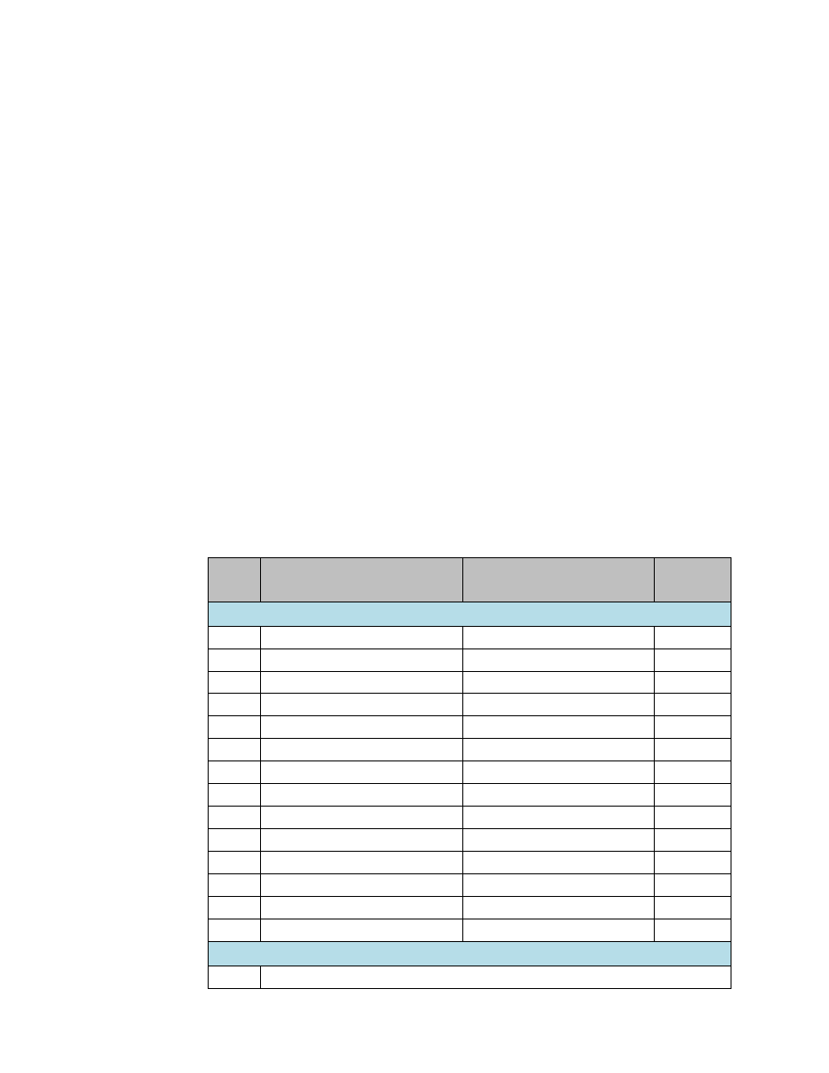
The first word of this data area is used for 16 status and control bits. As the table below 
shows, the Find Home, Go Home, Blending, and Stop Motion function blocks use the same 
bit definitions. Jogging uses some different bit definitions. Most of this data is for internal 
use only; it is not of interest to the application program. The exceptions to this are bit 1 
(Active  output),  which  can  be  monitored  for  a  Jogging  function  block,  and  bit  2  (Done 
output), which can be monitored for the other function block types. See the function block 
descriptions in this chapter for more information.  

Bit 

Description 

Find Home, Go Home, 
Blending, Stop Motion  

Jogging 

Least significant word 

Execute input, previous execution 


reserved 

Active output 


Done output 


reserved 

Error output 


Warning output 


Motion Started 

reserved 

reserved 

Enable input, previous execution 


Execute Triggered 

reserved 

reserved 

Jogging, Enable Backward active = 1  reserved 


Jogging, Enable Forward active = 1 

reserved 


10 

Previous Enable Backward Value 

reserved 


11 

Previous Enable Forward Value 

reserved 


12 

Runtime Error Occurred 

reserved 


13-15 

Not Used 

reserved 

reserved 

Most significant word 

Word 

Error ID / Warning ID of the function block error that occurred. See next page. 


User Manual 

Chapter 19 

GFK-1645M 

Dec 2019 


Motion Control Functions 

371 

19.1.4


Error Codes and Warnings for Motion Features 
(Hexadecimal) 

The following error codes are used for the motion function blocks. These error codes appear 

in word 2 of the function block’s 2 words of instance data, as described on the previous page.  
They  also  appear  in  each  function  block’s  Error  ID  out

put  and  in  the  channel,  error 

references:  %AI002,  003,  004,  and  005  for  channels  1,  2,  3,  and  4  respectively.  The 
application program should monitor error status using those references. 

Error Code 
(hex) 

Error Description 

14 

Specified  acceleration below  minimum  limit of 10 for channels 1,  2,  3 or below 
minimum limit of 90 for channel 4 

15 

Specified acceleration above maximum limit of 1,000,000 

16 

Specified deceleration is below minimum limit of 10 for channels 1, 2, 3, or below 
minimum limit of 90 for channel 4 

17 

Specified deceleration above maximum limit of 1,000,000 

18 

Specified Velocity is below minimum limit of 10 

19 

Specified Velocity is above maximum limit of 65000 

1B 

Specified home offset is negative, which is not valid 

1D 

Axis not configured for motion In the hardware configuration for HSC/PWM/PTO 

settings, channel function should be  selected as ‘Motion  Support’  to  be  able to 

initiate any motion command. 

1E 

Axis busy with Ramping. User logic issued a motion command on a channel that 
had Ramping already in progress. 

1F

13


Axis busy with Jogging.  
Only one motion function block is allowed to be active at a time, but user logic has 
issued another motion command while jogging command is still in progress. 

21

13


Axis busy with Blending. 
Only one motion function block is allowed to be active at a time, but user logic has 
issued another motion command while blending command is still in progress. 

22 

Find  Home  cannot  be  started  because  Final  Home  velocity  is  greater  than  Find 
Home velocity 

23 

Home switch Input is already on at the time of triggering Find Home command. 

24 

Go  Home  function  block  triggered  without  a  previously  successful  Find  Home 
being completed. 

25 

Specified number of profiles is above the maximum limit of 4. 

26 

Specified number of profiles is below the minimum limit of 1. 

27 

Configured pulse count is less than the minimum limit of 2. 

29

13


Axis busy with Find Home.  
Only one motion function block is allowed to be active at a time but user logic has 
issued another motion command while Find Home is still in progress. 


13

 If an active (not complete) function block instance is re-enabled while motion is still in progress, this condition is recorded as a 

warning. If a different function block is enabled while motion is in progress, this condition is recorded as an error. 

User Manual 

Chapter 19 

GFK-1645M 

Dec 2019 


Motion Control Functions 

372 

Error Code 
(hex) 

Error Description 

2A

13


Axis busy with Go Home.  
Only one motion function block is allowed to be active at a time, but user logic has 
issued another motion command while Go Home is still in progress. 

2B 

Motion  function  block  issued  before  the  axis  was  enabled  (i.e.  %Q0505, 
506,507,508 bits are low on respective axis).. 

2C 

No motion is in progress when Stop motion function block triggered. 

2E 

Channel not configured to support motion function blocks. For the motion features 
to be supported, the counter type should be either 4 Type A_32 or 1 Type A / 1 Type 
B_32 counters on settings tab. 

2F 

In continuous/rotary mode operation of the position register, high limit is less than 
or equal to low limit. 

30 

Blending motion parameters array exceeds reference memory size. For example: 
Each  profile  in  blending  contains  four  parameters  (acceleration,  deceleration, 
velocity, and distance). Each parameter occupies two words. So, for each profile 8 
words  of  memory  is  required.  Suppose  %AI120  is  assigned  for  blending  motion 
parameters input. If the number of profiles is 4, then 32 words of memory, starting 
from  %AI120,  needs  to  be  reserved  for  blending  motion  parameters.  But  %AI 
memory can only be up to %AI128. 

31 

Stop  motion  function  block  is  re-triggered  before  function  block  has  finished 
stopping motion. This is a warning. 

33 

Both enable forward, enable backward inputs are high on Jogging, which is invalid. 

34 

Motion cannot be started for the following reasons: 
Either motion function block was triggered while Stop Motion function block is still 
active  (not  complete),  or  the  axis  is  blocked  by  the  Stop  Motion  function  block 
(Execute input on Stop Motion function block is high).  Axis error. 

35 

Stop  Motion  function  block  is  issued  while  another  motion  function  block  is 
pending to start on same axis. This error occurs if a motion function block (Jogging, 
Blending, or Homing) is triggered on an axis and a Stop Motion function block is 
triggered before motion can start on that axis. 

37 

More than one instance of Stop motion function block triggered on the same axis.    

38 

Motion stopped due to stop mode (PLC has transitioned from Run mode to Stop 
mode), or power fail. Axis error. 

39 

Axis error present on the channel. Check %AI002, 3, 4, and 5 for axis error details 
on  respective  channel.  Axis  errors  can  be  cleared  by  a  low-to-high  transition  of 
output bits %Q489, 490,491, or 492 for channels 1, 2, 3, or 4 respectively. 


User Manual 

Chapter 19 

GFK-1645M 

Dec 2019 


Motion Control Functions 

373 

Axis and Function Block Errors 

Of the errors listed above, errors 2B, 34, and 38 are axis errors. All other errors are function 
block errors.  If any axis error is present on an axis, no motion can be initiated on that axis by 
any function block.  

Clearing Axis Errors 

Axis errors can be cleared by a low-to-high transition of output bits %Q489, 490, 491, or 492 
for channel 1, 2, 3, or 4. 

Axis errors are also cleared by any of the following: 


clearing/downloading a hardware configuration 


clearing/ downloading logic 


clearing of all memory 


clearing of initial values 

After axis errors are cleared in %AI memory, motion can be started by any function block. 

Operation of the Instance Registers 

While the function block’s Enable input is receiving power flow, function block inputs are 

stored to the Instance Registers, and function block outputs are updated continuously. 

When the function block’s 

Enable is not receiving power flow, the function block outputs 

are not updated. However, they are still updated to the Instance Registers.   

The  next  time  Enable  receives  power  flow,  the  output  status  data  stored  in  the  Instance 
Registers is updated to function block outputs. 

The  Instance  Register  references  should  not  be  overwritten  by  user  logic.  Overlapping 
reference addresses may cause erratic function block operation.  

Motion  Function  Block  Operation  in  PLC  Run-Stop-Run 
Transition or Loss of Power  

If power is lost or if the Micro PLC goes to Linear mode while a motion function is being 
executed, the motion stops immediately. 

When power returns or when the Micro PLC goes to Run mode, the error 0x38 (see above) 

is  logged  in  the  channel’s  %AI  memory  refer

ence.  The  same  error  is  generated  on  the 

function block output when its Enable input receives power flow. Error 0x38 is an axis error; 
no motion will occur on the axis until the error is cleared. 


User Manual 

Chapter 19 

GFK-1645M 

Dec 2019 


Motion Control Functions 

374 

19.1.5


Avoiding Abrupt Start/Stop of Motion 

The following condition must be satisfied in order to avoid abrupt start/stop of motion: 

n≥1

, where 

 or 


If n<1, abrupt start/stop of motion can happen. 

Example: 

For the Find Home function: 

Find Home Velocity = 1000 

Final Home Velocity = 500 

Acceleration = 10000 

Deceleration = 10000 

Offset = 0 

With these parameters, the values for Final Home Velocity and Deceleration yield a value of 

n=0.5,  which  does  not  satisfy  the  requirement  n≥1.  Instead  of  decelerating  to  home 

position, the axis goes immediately to zero velocity. To avoid this, select values for Velocity, 
Acceleration and Deceleration that satisfy the above condition. 

19.2


Finding a Home Position 

The Find Home function defines a Home (zero) position for the axis, relative to a physical 
location on a machine. The location is represented by a Home Switch, which is connected 
to a specific input on the Micro PLC. The Home Switch input must come from a  normally 
open contact. A normally closed contact cannot be used. 

The  Home  Switch  input  is  assigned  to  input  reference  %I002,  %I004,  %I006,  or  %I008 
depending on the channel. The input reference cannot be used as a standard input when 
the channel is used for Homing. 

When a Find Home Cycle is requested, the following sequence is executed: 

Figure 207 


User Manual 

Chapter 19 

GFK-1645M 

Dec 2019 


Motion Control Functions 

375 

1.


After  accelerating  to  the  configured  Find  Home  Velocity,  the  axis  moves  in  the 
specified direction until the Home Input signal is detected.  

2.


When the rising edge of Home Input signal is detected, the axis decelerates at the 
deceleration rate and stops. 

3.


The axis then accelerates in the opposite direction at the Final Home Velocity until 
the Home Input signal goes to 0. 

4.


Once the falling edge of the Home Input signal is detected (Home Input off as shown 
above), the axis decelerates and stops. 

5.


At the falling edge of the Home Input, the CPU starts capturing the motor position 
value. This continues until the motion stops and the axis makes a final move to the 
Home switch or to the Home Offset. 

6.


Zero  Home  Offset:  the  axis  accelerates  to  the  Final  Home  velocity.  It  then 
decelerates and stops at the edge transition of the Home Input. This is the Home 
position. The position register is automatically zeroed upon completion of the Find 
Home cycle. 

7.


Non-zero Home Offset: Depending on the value of the Home Offset and the motor 
position  captured  by  the  CPU,  the  axis  accelerates  to  the  Final  Home  Velocity  in 
either forward or reverse direction. The axis moves until it decelerates again to reach 
the Home Offset position. The position register is set to 0 when the axis reaches the 
Home Offset position. 

Figure 208 


User Manual 

Chapter 19 

GFK-1645M 

Dec 2019 


Motion Control Functions 

376 

19.2.1


Find Home Function Block 

The  application  program  uses  the  following  function  block  to  set  up  and  control  a  Find 
Home operation. 

Figure 209 


The channel’s Output Enable bit (for example, Q0505 for channel 1) must be set to 1 to use 

this or any other motion function block on the channel. If the Output Enable bit is not 1, the 
function will not execute, and a Channel Enable error will be reported.  

When  the  Enable  input  receives  power  flow  and  the  Execute  input  transitions  to  1,  the 
function  block  parameters  are  loaded.  If  the  parameters  are  not  valid,  a  warning  is 
generated, and the function does not start. If the parameters are valid, the motion starts in 
the direction (CW or CCW) specified by Axis Direction input, and the Active output is set to 
1. Active returns to 0 when the function complete, or is stopped.  

If the Enable input continues passing power flow after the motion completes, Find Home 
can be restarted with the same parameters by again generating a low to high transition on 
the Execute input. To execute the function block with different parameters, the Enable input 
must stop passing power flow. After changing the parameter values, the function block can 
be executed by again passing power flow to the Enable input and generating a low to high 
transition on the Execute input. 

The function block’s Enable output remains high as long as Enable Input is high.


If  the  Enable  input  stops  receiving  power  flow  while  motion  is  in  progress,  the  function 

block’s  Done  output  will  not  indicate  when  motion  stops.  In  this  case,  the  application 
program should monitor the Done output bit (bit 2) at address +0 of the function block’s 

assigned Instance data to determine when the motion is completed. 

Transitions  of  the  Execute  input  are  only  monitored  while  the  Enable  input  is  receiving 
power flow. While the Enable input receives power flow, the Execute input is monitored for 
a change in its status from the previous logic scan; if Enable and Execute transition in the 
same scan, the transition of Execute is not detected. Therefore, the application logic must 
not set both Enable and Execute either low or high in the same scan. If Enable and Execute 
were made low in the same scan, the Find Home function block would still see the Execute 
as high. If Execute and Enable were made high in the same scan, the Find Home function 
block would not see the transition in Execute status and motion would not start. 

User Manual 

Chapter 19 

GFK-1645M 

Dec 2019 


Motion Control Functions 

377 

Stopping Find Home 

Find Home can be stopped by:  


Executing a Stop Motion function block, as described later in this chapter. This stops 
any motion on the channel while leaving the channel active. 


Disabling the channel by setting its High-Speed Counter enable output bit to 0. No 
motion functions will operate on the channel while it is disabled. 

CAUTION 

To  avoid  abrupt  starting  and  stopping  of  motion,  the  ratio  of  Velocity/Acceleration  or 

Velocity/Deceleration must be ≥ 0.1. For details, refer to page 420.


Inputs to the Find Home Function Block 

Enable 

The Enable input provides power flow to the function block.  

Axis 

A Constant representing the channel (1, 2, 3, or 4) on which Find Home will 
be done.  

Execute 

Power flow to this input controls execution of the function.  

Motion 
Parameters 

Starting address of 6-word reference location in AI, AQ, or R memory for 

the motion speeds, which are specified in the channel’s configured units: 


Words 1, 2 

Homing acceleration: 
 

10 to 1,000,000 for channels 1, 2, and 3 


90 to 1,000,000 for channel 4. 

Words 3, 4 

Homing deceleration: 
 

10 to 1,000,000 for channels 1, 2, and 3 


90 to 1,000,000 for channel 4 

Word 5, 6 

Find Home velocity, from 15 to 65,000. . The velocity used 
to reach  Home position,  the Find Home velocity is usually 
high, to reach Home position quickly. The sum of velocities 
on all channels must not exceed 65,000. 

Final  Home 
Velocity 

Dword  variable  (%AI,  AQ,  R)  or  Constant  representing  the  velocity  used 
after the home switch is detected once. Final Home Velocity ranging from 
15 to 65,000 is slower than the Find Home velocity, for greater precision in 
arriving at the final Home Position. 

Home 
Offset 

Real  variable  (%AI,  AQ,  R)  or  constant  representing  the  Offset  from  the 
Home Switch.   

Axis 
Direction 
Input 

Boolean variable (%I, Q, M, G, T) or Constant specifying the axis direction.  
0 = Clockwise (CW), 1 = Counter-Clockwise (CCW). Note that the actual 
direction depends on the field connections and drive settings. 


User Manual 

Chapter 19 

GFK-1645M 

Dec 2019 


Motion Control Functions 

378 

Outputs of the Find Home Function Block 

Enable 
output 

Power flow output, passes power flow when it receives power flow from the 
Enable input. 

Axis 
Direction 
Output 

Boolean variable (Q0005 to Q0024). The Micro PLC output point for which 
direction  is  to  be  set.  0  =  clockwise,  1  =  counterclockwise.  The  actual 
direction  depends  on  the  field  connections  and  drive  settings.    The 
application  program  should  not  override  the  direction  output  during  the 
Homing operation. 

Done 

Boolean variable (%I, Q, M, G, T) for the Find Home completion status. Goes 
to 1 when motion is completed. If the Execute input is a pulse, rather than 
staying  continuously  on,  done  remains  1/on  for  one  scan  after  motion 
completes.  

Active 

Boolean variable (%I, Q, M, G, T). Set to 1 when motion starts on the channel. 
Resets to 0 when motion stops. 

Error 

Boolean variable (%I, Q, M, G, T) .  Set to 1 if an error has occurred within 
function block. See Error ID below. 

Error ID 

Word variable (%AI, AQ, R). If Error (ER) =1, this is an error ID. If Warning (WR) 
=1, this is the Warning ID. See the list of error definitions on page 371. 

Warning 

Optional  parameter.  Boolean  variable  (%I,  Q,  M,  G,  T).  Set  to  1  when  a 
warning has occurred. See Error ID above. Warning is generated when the 
same motion is triggered again while it is already in progress. 


User Manual 

Chapter 19 

GFK-1645M 

Dec 2019 


Motion Control Functions 

379 

19.2.2


Example Program Logic for Find Home 

Figure 210 


19.3


Moving to the Home Position 

The Go Home function moves the motor to a Home position that has been defined by the 
Find Home function. 

Figure 211 


User Manual 

Chapter 19 

GFK-1645M 

Dec 2019 


Motion Control Functions 

380 

If  a  Home  Offset  was  set  up  during  execution  of  the  Find  Home  function,  the  Go  Home 
function causes the motor to move to the Home Offset position instead. 

Figure 212 


The  number  of  pulses  or  the  distance  and  the  direction  of  motion  are  automatically 
detected based on the Position Register value.  

19.3.1


Go Home Function Block 

The application program uses the following function block to set up and control a Go Home 
operation: 

Figure 213 


The channel’s Output Enable bit (for example, Q0505 for channel 1) must be set t

o 1 to use 

this or any other motion function block. If the Output Enable bit is not 1, the function will 
not execute, and a Channel Enable error will be reported. 

When  the  Enable  input  receives  power  flow  and  the  Execute  input  transitions  to  1,  the 
functio

n’s parameters are loaded. If the parameters are not valid, an error code is generated, 

and the function does not start. If the parameters are valid, function execution starts and 
sets the Active output to 1. Active returns to 0 when the function complete, or is stopped. 

If the Enable input continues passing power flow after the function completes, Go Home 
can be restarted with the same parameters by generating a low to high transition on Execute 
input again. To execute the function block with different parameters, first stop motion and 
then stop passing power flow to the Enable input. Then, change the parameter values. The 
function  block  can  then  be  executed  by  passing  power  flow  to  the  Enable  input  and 
generating a low-to-high transition on the Execute input. 

User Manual 

Chapter 19 

GFK-1645M 

Dec 2019 


Motion Control Functions 

381 

The function block’s Enable output remains high as long as Enable Input is high.


If  the  Enable  input  stops  receiving  power  flow  while  motion  is  in  progress,  the  function 

block’s  Done  output  will  not  indicate  when  motion  stops.  In  this  case

,  the  application 

program should monitor the Done output bit (bit 2) at address +0 of the function block’s 

assigned Instance data to determine when the motion is completed. 

Transitions  of  the  Execute  input  are  monitored  only  while  the  Enable  input  is  receiving 
power flow. While the Enable input receives power flow, the Execute input is monitored for 
a change in its status from the previous logic scan; if Enable and Execute transition in the 
same scan, the transition of Execute is not detected. Therefore, the application logic must 
not set both Enable and Execute either low or high in the same scan. If Enable and Execute 
were made low in the same scan, the Go Home function block would still see the Execute as 
high. If Execute and Enable were made high in the same scan, the Go Home function block 
would not see the transition in Execute and motion would not start. 

Stopping Go Home 

Go Home can be stopped by:  


Executing a Stop Motion function block, as described later in this chapter. This stops 
any motion on the channel while leaving the channel active. 


Disabling the channel by setting its High-Speed Counter enable output bit to 0. No 
motion functions will operate on the channel while it is disabled. 

CAUTION 

To avoid abrupt starting and stopping of motion, the ratio of Velocity/Acceleration or 

Velocity/Deceleration must be ≥ 0.1. For 

details, refer to page 374. 


User Manual 

Chapter 19 

GFK-1645M 

Dec 2019 


Motion Control Functions 

382 

Inputs to the Go Home Function Block 

Enable 

The Enable input provides power flow to the function block. 

Axis 

A Constant representing the channel (1, 2, 3, or 4) on which Go Home will 
be done.  

Execute 

Power flow to this input controls execution of the function. Rising edge is 
detected to load the parameters and start execution of the function block.  

Acceleratio

Dword variable or Constant representing the acceleration rate, from 10 to 
1,000,000. 90 to 1,000,000 for channel 4. 

Deceleratio

Dword variable or Constant representing the deceleration rate, from 10 to 
1,000,000. 90 to 1,000,000 for channel 4. 

Go  Home 
Velocity 

Dword  variable  or  Constant  representing  the  velocity  at  which  the  Go 
Home  function  is  to  be  carried  out.  From  15  to  65,000.  The  sum  of 
velocities on all channels must not exceed 65,000. 

Outputs of the Go Home Function Block 

Enable 
output 

Power flow output, passes power flow when it receives power flow from 
the Enable input. 

Axis 
Direction 
Output 

Boolean  variable  (Q0005  to  Q0024).  The  Micro  PLC  output  point  for 
which  direction  is  to  be  set.  0  =  clockwise,  1  =  counterclockwise.    The 
actual direction depends on the field connections and drive settings. The 
application program should not override the direction output during the 
Homing operation. 

Done 

Boolean  variable  (%I,  Q,  M,  G,  T)  for  the  GO  Home  completion  status. 
Goes to 1 when motion is completed and remains 1 until the next homing 
cycle is started and Execute is continuously on. If the Execute input is a 
pulse, rather than staying continuously on, Done remains 1/on for one 
scan after motion completes.  

Active 

Boolean  variable  (%I,  Q,  M,  G,  T)  for  the  Go  Home  Active  status.  1  = 
Homing in progress. 0 if motion is complete or has been stopped. 

Error 

Boolean variable (%I, Q, M, G, T) for the Go Home function block error 
status.  Set to 1 if an error has occurred within function block. See Error ID 
below. 

Error ID 

Word variable. If Error (ER) =1, this is an Error ID. If Warning (WR) =1, this 
is the Warning ID. See the list of error definitions on page 371. 

Warning 

Optional parameter. Boolean variable (%I, Q, M, G, T). Set to 1 when a 
warning has occurred. See Error ID above. Warning is generated when the 
same motion is triggered again while it is already in progress. 


User Manual 

Chapter 19 

GFK-1645M 

Dec 2019 


Motion Control Functions 

383 

19.3.2


Example Program Logic for Go Home 

Figure 214 


19.4


Jogging 

A Jogging move consists of Ramp Up (acceleration), At Velocity and Ramp Down 
(deceleration) velocities. 

Figure 215 


User Manual 

Chapter 19 

GFK-1645M 

Dec 2019 


Motion Control Functions 

384 

19.4.1


Jogging Function Block 

The application program uses the following function block to set up and control Jogging. 

Figure 216 


The channel’s Output Enable bit (for example, Q0505 for channel 1) must be set to 1 to use 

this or any other motion function block. If the Output Enable bit is not 1, the function will 
not execute, and a Channel Enable error will be reported. 

When the Enable input receives power flow, if no motion is active on the channel and either 
Enable  Forward  (EF)  or  Enable  Backward  (EB)  begins  passing  power  flow,  the  function

’s 

parameters are loaded. If the parameters are not valid, an error code is generated, and the 
function does not start. If the parameters are valid and the Enable input is high, execution 
starts  in  the  forward  (clockwise)  direction  if  Enable  Forward  is  high,  or  in  the  reverse 
(counterclockwise) direction if Enable backward is high. The Active output is set to 1. Motion 
starts at the specified input Acceleration value and continues at the specified input Velocity 
until power flow is removed from EF or EB. The axis then decelerates at the Deceleration 
value.  Active returns to 0 when the function is fully stopped.  

If both Enable Forward and Enable Backward pass power flow, an error is returned. When 
either input subsequently goes low, motion starts in the other direction and the error clears 
automatically.  

If the Enable input continues passing power flow, Jogging can be restarted with the same 
parameters by passing power flow to the EF or EB input again. To execute the function block 
with different parameters, first stop motion. The Enable Forward or Enable Backward input 
must stop passing power flow. After changing the parameter values, the application logic 
can again pass power flow to the Enable Forward or Enable Backward input. 

Enable Forward / Backward input level is not monitored unless the Enable input is receiving 
power  flow.  The  Enable  Forward  /  Enable  Backward  inputs  are  level-triggered,  not edge-
triggered. 

The function block’s Enable output transitions to 0 automatically when EN input becomes 

0. 

If  the  Enable  input  stops  receiving  power  flow  while  motion  is  in  progress,  the  function 

block’s  Active  output  will  not  indicate  when  motion  stops.  In  this  case,  the  application 

program should monitor the Active output bit (bit 1) at address +0 of the function 

block’s 

assigned Instance data to determine when the motion is completed. 

User Manual 

Chapter 19 

GFK-1645M 

Dec 2019 


Motion Control Functions 

385 

Stopping Jogging 

Jogging can be stopped by: 


Executing a Stop Motion function block, as described later in this chapter. This stops 
any motion on the channel while leaving the channel active. 


Disabling the channel by setting its High-Speed Counter enable output bit to 0. No 
motion functions will operate on the channel while it is disabled. 

CAUTION 

To  avoid  abrupt  starting  and  stopping  of  motion,  the  ratio  of  Velocity/Acceleration  or 

Velocity/Deceleration must be ≥ 0.1. For details, 

refer to page 374. 

Inputs to the Jogging Function Block 

Enable 

The Enable input provides power flow to the function block.  

Axis 

A Constant representing the channel (1, 2, 3, or 4) on which Jogging will 
be done. 

Enable 
Forward 

If  the  Enable  input  is  passing  power  flow,  power  flow  to  EF  enables 
forward motion (clockwise) of the specified axis and starts the Jogging 
operation.  If Jogging is already in progress, removing power flow to EF 
stops motion. 

Enable 
Backward 

If  the  Enable  input  is  passing  power  flow,  power  flow  to  EB  enables 
backward motion (counter-clockwise) of the specified axis and starts the 
jogging operation.  If Jogging is already in progress, removing power flow 
to EB stops motion. 

Acceleration  Dword  variable  (AI,  AQ,  R)  or  Constant  representing  the  jogging 

acceleration rate, between 10 and 1,000,000 for channel 1 to 3 and 90 to 
1,000,000 for channel 4. 

Deceleration  Dword variable (AI, AQ, R) variable or Constant representing the jogging 

deceleration rate, between 10 and 1,000,000 for channel 1 to 3 and 90 
to 1,000,000 for channel 4. 

Velocity 

Dword variable (AI, AQ, R)  or Constant representing the velocity rate, 
between 15 and 65,000. The sum of velocities on all channels must not 
exceed 65,000. 


Content      ..     24      25      26      27     ..