EMERSON PACSystems VersaMax MICRO PLC & NANO PLC. USER MANUAL (2019) - page 25
User Manual
Chapter 18
GFK-1645M
Dec 2019
High-Speed Counter, PWM, and Pulse Train Operation
354
Changing the Load Correction Time
The Load Correction time can be changed within the range 0 to 200µS by sending the new
value in a COMMREQ, as explained later in this chapter.
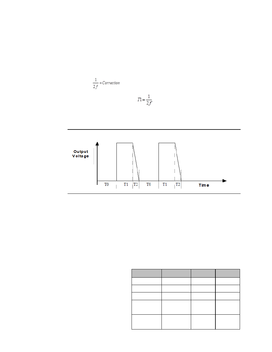
An example is illustrated below.
In the diagram, T0 is the OFF Time, which is
,
where
f is the pulse frequency.
,
T2 = Optical Isolator Delay,
and T1+T2 = ON Time.
Figure 198
18.7
Pulse Train Outputs
Pulse Train Outputs can be used to control stepper motors.
18.7.1
Configuring a Pulse Train Output
Configuring a channel as a Pulse Train Output is done by setting the Channel Function to
Pulse Train in the PLC configuration.
18.7.2
Program References for Pulse Train Outputs
The following program references are assigned for use by Pulse Train Outputs.
Channel 1
Channel 2
Channel 3 Channel 4
Pulse Train Complete
I0494
I0495
I0496
I0511
Enable Output
Q0505
Q0506
Q0507
Q0508
Start Pulse Train
Q0494
Q0495
Q0496
Q0511
Frequency:16 Bit Mode
32 Bit Mode
AQ123
AQ125
AQ127
AQ121
AQ120
AQ123
AQ126
AQ117
Number of Pulses: 16 bit mode
32 Bit Mode
AQ124
AQ126
AQ128
AQ122
AQ 121-122
AQ124-125
AQ127-128 AQ 118-119