EMERSON PACSystems VersaMax MICRO PLC & NANO PLC. USER MANUAL (2019) - page 27
 

  Index      Manuals     EMERSON PACSystems VersaMax MICRO PLC & NANO PLC. USER MANUAL (2019)


Search            copyright infringement  


Content      ..     25      26      27      28     ..


EMERSON PACSystems VersaMax MICRO PLC & NANO PLC. USER MANUAL (2019) - page 27


User Manual 

Chapter 19 

GFK-1645M 

Dec 2019 


Motion Control Functions 

386 

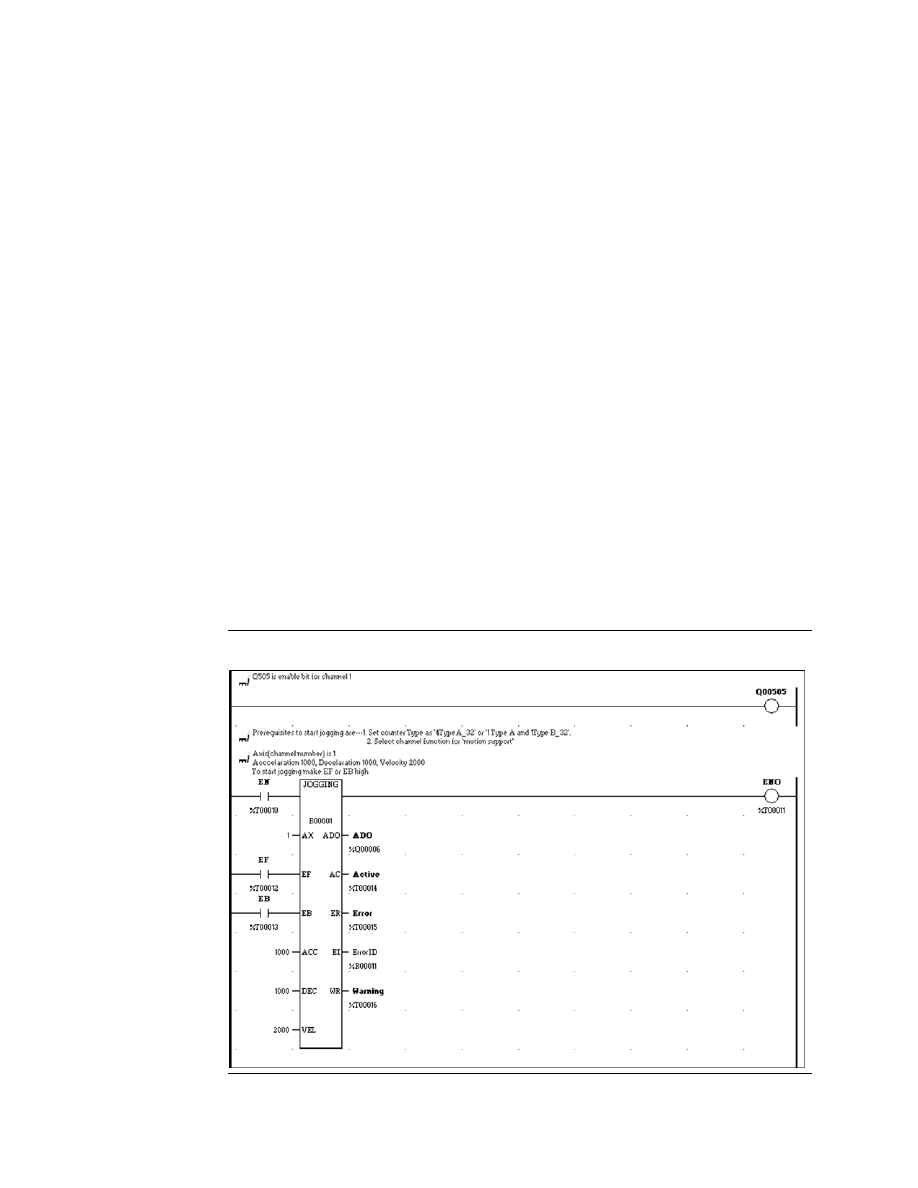
Outputs of the Jogging Function Block 

Enable 
output 

Power flow output passes power flow when it receives power flow from 
the Enable input.  

Axis Direction 
Output 

Boolean  Variable  (Q0005  to  Q0024).  The  Micro  PLC  output  point  for 
which  direction  is  to  be  set.  0  =  clockwise,  1  =  counterclockwise.  The 
actual  direction  depends  on  the  field  connections  and  drive  settings.  
The application program should not override the direction output during 
the motion operation. 

Active 

Boolean variable (%I, Q, M, G, T) for the Jogging Active status.  1 = Jogging 
in progress. 0 = Jogging complete or stopped,   

Error 

Boolean variable (%I, Q, M, G, T) for the error status. Set to 1 if an error 
has occurred within function block. See Error ID below.  

Error ID 

Word variable (%AI, AQ, R). If Error (ER) =1, this is an Error ID. If Warning 
(WR) =1, this is the Warning ID. See the list of error definitions on page 
371. 

Warning 

Optional parameter. Boolean variable (%I, Q, M, G, T). Set to 1 when a 
warning has occurred. See Error ID above. Warning is generated when 
the same motion is triggered again while it is already in progress.  

19.4.2


Example Program Logic for Jogging 

Figure 217 


User Manual 

Chapter 19 

GFK-1645M 

Dec 2019 


Motion Control Functions 

387 

19.5


Blending 

A  Blended  Move  consists  of  up  to  four  successive  moves  that  are  executed  without  the 
output  value  returning  to  zero  between  moves.  The  speed  (pulse  rate)  and  distance 
(number of pulses) for each of the blended moves can be defined. Transition to the speed 
of the next move uses ramping.  At the end of each blended move, when the motor has 
moved the defined number of pulses, the motor must be at the speed set for the next move 
in the sequence. 

The simplest form of blended move is shown below. 

Figure 218 


Because each Blend profile is equal to a normal ramping profile, a Pulse train with Ramp can 
be  done  using  a  Blended  move  with  just  one  blending  profile.  Use  this  method  if  the 
hardware configuration selected is 4 Type A_32 or 1 Type A/1 Type B_32. 

Each  move  can  use  any  of  the  combinations  of  Ramp  up  (acceleration),  At  Velocity  and 
Ramp  Down  (deceleration)  states.    These  combinations  depend  on  velocity  of  the  next 
move in the sequence. 

The parameters of each profile are used until the velocity of the next move is reached.  

Based upon the Number of Pulses and the input parameters, the acceleration, deceleration 
and the flat regions of the profile are calculated in order to reach the target frequency of 
next profile. The motion is then performed with the calculated parameters. 

19.5.1


Examples of Blended Moves 

This section describes some different Blended Move operations.  

Example 1 

In this example, all of the moves have sufficient number of pulses and acceleration to 
reach the desired velocity. 

Figure 219 


User Manual 

Chapter 19 

GFK-1645M 

Dec 2019 


Motion Control Functions 

388 

In this example,  segments 1, 2, and 3 use the profile 1 parameters: 


The number of pulses for segments 1, 2, and 3 are from distance 1.  


Segment 1 accelerates at acceleration 1.  


Segment 2 moves at velocity 1. 


Segment  3  decelerates  at  deceleration  1.  For  segment  3,  while  calculating  the 
number of pulses, the velocity of profile 2 (segment 4) is taken as the final velocity.  

Segments 4 and 5 use the profile 2 parameters:  


Segment 4 moves at velocity 2. 


Segment 5 accelerates at acceleration 2. 

The final aim of each move is to reach the next move desired velocity. So in Profile 1, first 
the  acceleration  pulses  are  calculated  for  segment  1,  then  the  deceleration  pulses  are 
calculated  for  segment  3.  The  remaining  pulses  are  generated  at  the  profile  1  desired 
velocity. 

Example 2 

In this example, the distance 1 value in profile 1 is not enough to reach velocity 1. So in 
profile 2 (segment 2), accel2 and pulses2 are used to reach velocity 2. Velocity 2 and velocity 
3 are configured as equal. 

Figure 220 


Example 3 

Figure 221 


User Manual 

Chapter 19 

GFK-1645M 

Dec 2019 


Motion Control Functions 

389 

In this example, for profile 1: 

1.


The acceleration to reach velocity 1 is calculated,  

2.


Then the acceleration needed to reach velocity 2 from velocity 1 is calculated.  

3.


The  remainder  of  profile  1  is  run  at  velocity  1.  In  this  example,  all  of  profile  1  is 
required for acceleration, so there is no constant velocity (dotted line) in profile 1. 

Profile 3 

 Like profile 1, distance 3 is just sufficient to accelerate to velocity 4, so profile 3 

has no motion at velocity 3. 

Profile 4 consists entirely of deceleration. 

Example 4 

In this example, in Profile 1, the acceleration is just enough to reach velocity 1. In profile 2, 
segment 2, deceleration 2 is used to reach velocity 2. Segment 3 of profile 2 is at velocity 2. 
Segment 4, ramps up at acceleration 2 to reach velocity 3. 

Figure 222 


Example 5 

In profile 1, segment 1 accelerates from zero to velocity 1 then decelerates down to 
velocity 2 from velocity 1 in segment 2. Since the distance is just enough for these 
segments, profile 1 has no motion at velocity 1. 

Figure 223 


User Manual 

Chapter 19 

GFK-1645M 

Dec 2019 


Motion Control Functions 

390 

19.5.2


Blending Function Block 

The application program uses the following function block to set up and control Blended 
Moves operation: 

Figure 224 


The channel’s Output Enable bit (for example, Q0505 for channel 1) must be set to 1 to use 

this or any other motion function block. If the Output Enable bit is not 1, the function will 
not execute, and a Channel Enable error will be reported. 

When the Enable input receives power flow, if the Execute input is set to 1, the function’s 

parameters are loaded. If the parameters are not valid, an error code is generated, and the 
Blending  function  does  not  start.  If  the  parameters  are  valid,  the  function  block  starts 
execution and sets the Active output to 1. The Active output returns to 0 when the function 
completes, or is stopped.  

If the Enable input continues passing power flow, Blending can be restarted with the same 
parameters by generating a low to high transition on Execute input again. To execute the 
function block with different parameters, stop the motion.  Then, remove power flow from 
the Enable input. After changing the parameter values, the function can be  executed by 
reapplying power flow to the Enable input and generating a low to high transition on the 
Execute input. 

The function block’s Enable output transitions to 0 automatically when EN input becomes 

low. 

Transitions  of  the  Execute  input  are  only  monitored  while  the  Enable  input  is  receiving 
power flow. While the Enable input receives power flow, the Execute input is monitored for 
a change in its status from the previous logic scan; if Enable and Execute transition in the 
same scan, the transition of Execute is not detected. Therefore, the application logic must 
not set both Enable and Execute either low or high in the same scan. If Enable and Execute 
were made low in the same scan, the Blending function block would still see the Execute 
input as high. If Execute and Enable were made high in the same scan, the Blending function 
block would not see the transition in Execute status and motion would not start. 

The motion status can be monitored by the Active output of the function block. If the Active 
output is 1, motion is in progress. While motion is in progress, the Done, Error, and Warning 
outputs should be 0. After the completion of the motion, the Active output is set to 0 and 
the Done output is set to 1. 

User Manual 

Chapter 19 

GFK-1645M 

Dec 2019 


Motion Control Functions 

391 

If  the  Enable  input  stops  receiving  power  flow  while  motion  is  in  progress,  the  function 

block’s  Done  output  will  not  indicate  when  motion  stops.  In  this  case,  the  application 
program should monitor the Done output bit (bit 2) at address +0 of the function block’s 

assigned Instance data to determine when the motion is completed. 

When there is any error during the motion or at the start of the motion, the Error indication 
and  the  Error  Number  are  updated  to  the  Error  output  and  the  Error  ID  specified  in  the 
function block.  

Stopping Blending 

Blending can be stopped by:  


When  the  PLC  has  gone  through  Run-Stop  transition.  After  coming  back  to  Run 
mode, an axis error (0x38) is logged into the %AI002 register and also at the Blending 
function  block's  Error  ID  output.  The  error  in  %AI002  must  be  cleared  using  the 
predefined reset bits for any other motion to start on that axis. 


When the PLC is power cycled. 


Executing a Stop Motion function block, as described later in this chapter. This stops 
any motion on the channel while leaving the channel active. 


Disabling the channel by setting its enable output bit to 0. No motion functions will 
operate on the channel while it is disabled. 

CAUTION 

To avoid abrupt starting and stopping of motion, the ratio of Velocity/Acceleration or 
Velocity/Deceleration must 

be ≥ 0.1. For details, 

refer to page 374. 

Inputs to the Blending Function Block 

Because some of the profiles in a Blended Move may not have Ramp Up, At Velocity, and 
Ramp Down segments, some parameters may not be used. 

Enable 

The Enable input provides power flow to the function block.  

Axis 

A Constant representing the channel (1, 2, 3, 4) on which the Blended Move 
will be done.  

Execute 

Power  flow  to  this  input  starts  execution  of  the  function.  Rising  edge  is 
detected to load the parameters and start execution of the function block. 

Number  of 
Profiles 

Word variable or Constant representing the number of profiles (1, 2, 3, or 
4).  Data  for  each  profile  must  be  present  in  the  Motion  Parameters 
references (below). 

Axis 
Direction 
Input 

Boolean variable (%I, Q, M, G, T) or a Constant specifying the axis direction.  
0  =  Clockwise  (CW),    1  =  Counter-Clockwise  (CW).  The  actual  direction 
depends on the field connections and drive settings. 

User Manual 

Chapter 19 

GFK-1645M 

Dec 2019 


Motion Control Functions 

392 

Motion 
Parameter

Starting address of 32-word reference location in AI, AQ, or R memory that 
will  be  used  for  the  Motion  Parameters  of  each  profile.  Acceleration, 

deceleration and velocity are specified in the channel’s configured units.


Words 1, 2 

Profile 1 acceleration, from 10 to 1,000,000 for channels 
1, 2, and 3; 90 to 1,000,000 for channel 4 

Words 3, 4 

Profile 1 deceleration, from 10 to 1,000,000 for channels 
1, 2, and 3; 90 to 1,000,000 for channel 4 

Words 5, 6 

Profile 1 velocity, from 15 to 65,000 


Words 7, 8 

Real value. Distance in user units for profile 1 


Words 9 to 16  Profile  2  acceleration,  deceleration,  velocity,  and 

distance, as above for Profile 1 


Words  17  to 
24 

Profile  3  acceleration,  deceleration,  velocity,  and 
distance, as above for Profile 1 


Words  25  to 
32 

Profile  4  acceleration,  deceleration,  velocity,  and 
distance, as above for Profile 1 

Outputs of the Blended Moves Function Block 

Enable 
Output 

Power flow output, passes power flow when it receives power flow from 
the Enable input. 

Axis 
Direction 
Output 

Boolean variable (Q0005 to Q0024). The Micro PLC output point for which 
direction is to be set. 0 = clockwise, 1 = counterclockwise.  The application 
program  should  not  override  the  direction  output  during  the  motion 
operation. 

Done 

Boolean variable (%I, Q, M, G, T) for the Blending completion status. Goes 
to 1 or passes power flow when motion is complete. If the Execute input is 
a pulse, rather than continuously on, Done remains 1/on for one scan after 
motion completes.   

Active 

Boolean  variable  (%I,  Q,  M,  G,  T).  Set  to  1  when  motion  starts  on  the 
channel. Resets to 0 when motion stops. 

Error 

Boolean variable (%I, Q, M, G, T). Set to 1 if an error has occurred within 
function block. See Error ID below. 

Error ID 

Word variable (%AI, AQ, R). If Error (ER) =1, this is an Error ID. If Warning 
(WR) =1, this is the Warning ID.  See the list of error  definitions on page 
371. 

Warning 

Optional  parameter.  Boolean  variable  (%I,  Q,  M,  G,  T).  Set  to  1  when  a 
warning has occurred. See Error ID above.  Warning is generated when the 
same motion is triggered again while it is already in progress. 


User Manual 

Chapter 19 

GFK-1645M 

Dec 2019 


Motion Control Functions 

393 

19.5.3


Example Program Logic for Blending 

Figure 225 


User Manual 

Chapter 19 

GFK-1645M 

Dec 2019 


Motion Control Functions 

394 

19.6


Stopping Motion on an Axis 

As mentioned for the individual functions, motion can be stopped by: 


Disabling the channel by setting its High-Speed Counter enable output bit to 0. This 
stops all motion functions on the channel. 


Executing a Stop Motion function block as described below. This stops any motion 
on the channel while leaving the channel active. 

19.6.1


Stop Motion Function Block 

The  application  program  can  use  the  Stop  Motion  function  block  to  stop  any  motion 
operation: 

Figure 226 


When the Execute input receives power flow and the Enable input is high, and there is no 
stop motion instance on the axis, the parameters are loaded. If the parameters are valid, a 
low to high transition on the Execute input starts execution, stops the axis with the specified 
input deceleration value (or immediately) based on the value of Stop mode input,  and sets 
the Active output to 1. The Done output goes to 1 when the axis stops and the Active output 
returns to 0. Done remains high until the Execute input transitions low. If Execute is a pulse, 
Done remains high for one scan after the axis stops (Active becomes low). If the parameters 
are not valid, an error code is generated, and the function does not start.  

To  execute  the  function  block  with  different  parameters,  remove  power  flow  from  the 
Enable and Execute inputs. Then, change the parameters. The function block will execute 
with the new parameters when power flow is applied to the Enable input and a low to high 
transition occurs on the Execute input.  

Execute input transitions are not monitored unless the Enable input is receiving power flow. 
When the Enable input receives power flow, the Execute input is monitored for a change in 
status from the previous logic scan. Therefore, Enable and Execute should not be made low 
in the same scan or be made high in the same scan. If both Enable and Execute were set to 
low in the same logic scan, the change to the Execute state would not be seen by the Stop 

Motion  function  block  because  Enable  is  already  low.  So  although  the  function  block’s 

Execute input is low, it still controls the axis and no motion can occur on that axis. 

If  the  Enable  input  stops  receiving  power  flow  while  motion  is  in  progress,  the  function 

block’s  Done  output  will  not  indicate  when  motion  stops.  In  this  case,  the  application 

User Manual 

Chapter 19 

GFK-1645M 

Dec 2019 


Motion Control Functions 

395 

program sho

uld monitor the Done output bit (bit 2) at address +0 of the function block’s 

assigned Instance data to determine when the motion is completed. 

More than One Stop Motion Function Block for an Axis 

If the application logic contains more than one Stop Motion function block for an axis, the 
state of the Execute input of the last Stop Motion function block in the scan that has positive 
power flow determines whether the Stop Motion function block controls motion on the axis. 

For example, suppose the logic contains two Stop Motion function blocks for the same axis, 
and jogging is running on that axis. Execute is triggered for the first Stop Motion function 
block, but the Execute input of the second Stop Motion function block is 0. The first instance 
of the Stop Motion function block takes control of the axis and stops the current jogging. 
After  jogging  stops,  because  the  Execute  input  of  second  (or  last)  Stop  Motion  function 
block is still 0, Stop Motion is not controlling the axis and jogging can again be started on 
the axis. 

CAUTION 

To  avoid  abrupt  starting  and  stopping  of  motion,  the  ratio  of  Velocity/Acceleration  or 

Velocity/Deceleration must be ≥ 0.1. For 

details, refer to page 374. 

Inputs to the Stop Motion Function Block 

Enable 

The Enable input provides power flow to the function block.  

Axis 

A Constant representing the channel (1, 2, 3, or 4) on which motion will 
stop. 

Execute 

Power flow to this input controls execution of the Function Block.  

Stop Mode 

Boolean variable (%I, Q, T, M, G) or Constant to control the Stop Mode. 0 
= decelerate to stop (normal stop mode). 1 = stop immediately. 

Deceleration  Optional  Dword  variable  or  Constant  representing  the  jogging 

deceleration rate, between 10 and 1,000,000 for channels 1, 2, and 3. 90 
to 1,000,000 for channel 4. 


User Manual 

Chapter 19 

GFK-1645M 

Dec 2019 


Motion Control Functions 

396 

Outputs from the Stop Motion Block 

Enable output  Boolean power flow output, passes power flow when it receives power 

flow from the Enable input. 

Done 

Boolean variable (%I, Q, M, G, T). Goes to 1 when motion is has stopped. 
If  the  Execute  input  is  a  pulse,  rather  than  continuously  on,  Done 
remains 1/on for one scan.   

Active 

Boolean variable (%I, Q, M, G, T) for the function status.  1 = Stopping in 
progress.  

Error 

Boolean variable (%I, Q, M, G, T). Set to 1 if an  error has occurred within 
function block. See Error ID below. 

Error ID 

Word variable (%AI, AQ, R). If Error (ER) =1, this is an Error ID. If Warning 
(WR) =1, this is the Warning ID . See the list of error definitions on page 
374. 

Warning 

Optional parameter. Boolean variable (%I, Q, M, G, T). Set to 1 when a 
warning has occurred. See Error ID above. Warning is generated when 
the same motion is triggered again while it is already in progress. 

19.6.2


Example Program Logic for Stop Motion 

Figure 227 


User Manual 

Chapter 20 

GFK-1645M 

Dec 2019 


Fault Handling 

397 

Chapter 20:


Fault Handling 

This chapter discusses how the Micro PLC handles system faults.  

20.1


Faults and Fault Handling 

A fault is a failure or condition that can affect the operation and performance of the system. 
A fault may impair the ability of the PLC to control a machine or process. 

20.1.1


Fault Handling 

When a fault is detected, the PLC processes the fault and sets the corresponding system 

bit(s) (See ‘System Bit Reference Table’). The PLC logs the fault into a fault table.  There are 

two different fault tables: 


The I/O Fault Table 


The PLC Fault Table 

Contents of the fault tables can be monitored and cleared from the programmer.  

20.1.2


Classes of Faults 

The Micro PLC detects several classes of faults, including: 


Internal Failures 


Non-responding circuit boards 


Memory checksum errors 


External Failures 


Sequence fault 


Operational Failures 


Communication failures 


Configuration failures  


Password access failures 

20.2


System Responses to Faults 

Some faults can be tolerated, while others require that the PLC shut down. I/O failures may 
be tolerated by the PLC, but not be acceptable for the application. Operational failures can 
normally be tolerated. 


User Manual 

Chapter 20 

GFK-1645M 

Dec 2019 


Fault Handling 

398 

20.2.1


Fault Actions 

The PLC categorizes different groups of faults as: 


Informational 


Diagnostic 


Fatal 

The PLC logs all faults in the appropriate fault table.  For diagnostic and fatal faults, the PLC 
sets any associated diagnostic variables. The following table lists the fault action, associated 
fault table, and diagnostic variables for different types of faults. In addition, if the fault is a 
fatal fault, the PLC halts the system (STOP/FAULTED mode) to prevent possible damage to 
the equipment, or personal injury.  

Fault Group 

Action 

Fault Table 

Diagnostic Variables 

System Configuration 
Mismatch 

Fatal 

PLC Fault Table 

sy_flt(%SC10)  any_flt(%SC9)  sy_pres(%SC12) cfg_mm(%SA9) 

Expansion Unit 
Configuration 
Mismatch 

Fatal 

PLC Fault Table 

sy_flt(%SC10)  any_flt(%SC9)  sy_pres(%SC12) cfg_mm(%SA9) 

PLC CPU Hardware 
Failure 

Fatal 

PLC Fault Table 

sy_flt(%SC10)  any_flt(%SC9)  sy_pres(%SC12) hrd_cpu(%SA10) 

PLC Software Failure 
(see below) 

Fatal 

PLC Fault Table 

sy_flt(%SC10)  any_flt(%SC9)  sy_pres(%SC12) sft_cpu(%SB13) 

PLC Store Failure (see 
below) 

Fatal 

PLC Fault Table 

sy_flt(%SC10)  any_flt(%SC9)  sy_pres(%SC12) stor_er(%SB14) 

Program Checksum 
Failure 

Fatal 

PLC Fault Table 

sy_flt(%SC10)  any_flt(%SC9)  sy_pres(%SC12) pb_sum(%SA1) 

No User Program on 
Power-up 

Diagnostic  PLC Fault Table 

sy_flt(%SC10)  any_flt(%SC9)  no_prog(%SB9)   

Corrupted User RAM 

Fatal 

PLC Fault Table 

sy_flt(%SC10)  any_flt(%SC9)  sy_pres(%SC12) bad_ram(%SB10) 

Unknown PLC Fault 

Fatal 

PLC Fault Table 

sy_flt(%SC10)  any_flt(%SC9)  sy_pres(%SC12)  

Unknown I/O Fault 

Fatal 

I/O Fault Table 

io_flt(%SC11)  any_flt(%SC9)  io_pres(%SC13)   

PLC Fault Table Full 

Diagnostic  - 

sy_flt(%SC10)   


I/O Fault Table Full 

Diagnostic  - 

io_full(%S10)   


Application Fault 

Diagnostic  PLC Fault Table 

sy_flt(%SC10)  any_flt(%SC9)  sy_pres(%SC12) apl_flt(%SA3) 

Password Access 
Failure 

Diagnostic  PLC Fault Table 

sy_flt(%SC10)  any_flt(%SC9)  sy_pres(%SC12) bad_pwd(%SB11) 

Constant Sweep Time 
Exceeded 

Diagnostic  PLC Fault Table 

sy_flt(%SC10)  any_flt(%SC9)  sy_pres(%SC12) ov_swp(%SA2) 

Loss of Expansion Unit  Diagnostic  I/O Fault Table 

io_flt(%SC11)  any_flt(%SC9)  io_pres(%SC13)  los_iom(%SA14) 

Addition of Expansion 
Unit 

Diagnostic  I/O Fault Table 

io_flt(%SC11)  any_flt(%SC9)  io_pres(%SC13)  add_iom(%SA19) 


User Manual 

Chapter 20 

GFK-1645M 

Dec 2019 


Fault Handling 

399 

PLC 
Software 
Failure 

If a PLC Software Failure is logged, the PLC immediately goes into Error 
Sweep mode. The only way to clear this condition is to cycle power.  

PLC 

Store 

Failure 

A  sequence  store  is  the  storage  of  program  blocks  and  other  data 
preceded by the special Start-of-Sequence command and ending with the 
End-of-Sequence command. If communications with the programmer are 
interrupted or if any other failure terminates the download, the PLC Store 
Failure fault is logged. As long as this fault is present in the system, the PLC 
will not transition to Run mode. 

20.3


Fault References 

The  PLC  defines  a  set  of  special  fault  references  that  can  be  included  in  the  application 
program to check for fault conditions, and allow appropriate action to be taken should one 
of these faults occur.  

These  special  fault  references  remain  set  until  the  PLC  is  cleared  or  until  the  application 
program clears the fault.  

20.3.1


Example Program Logic for Fault References 

This example ladder logic shows how the fault reference  ov_swp can be programmed to 
check for an over-sweep condition, then cleared. In this example, an indicator light_01 is 
turned on to alert the operator that an over-sweep has occurred. After fixing any problem in 
the  application,  the  operator  presses  a  pushbutton.  This  causes  program  input  %I0035 
contact to pass power flow to the ov_swp  reference, which clears the associated memory 
location. 

Figure 228 


User Manual 

Chapter 21 

GFK-1645M 

Dec 2019 


Elements of an Application Program 

400 

Chapter 21:


Elements of an Application 
Program 

This chapter provides basic information about the application program. 


Structure of an application program 


Subroutines 


Program languages 


Instruction set 

21.1


Structure of an Application Program 

The  application  program  consists  of  all  the  logic  needed  to  control  the  operation  of  the 
Nano or Micro PLC. 

Application programs are created using the programming software and transferred to the 
PLC. Programs are stored in non-volatile memory. 

During the CPU Sweep (described in Chapter 17:), the Micro PLC reads input data and stores 
the data in its configured input memory locations. The Micro PLC then executes the entire 
application program once, utilizing this fresh input data. Executing the application program 
creates new output data that is placed in the configured output memory locations. 

After completing the end of the application program, the CPU provides the output data to 
the output points. 

Figure 229 


User Manual 

Chapter 21 

GFK-1645M 

Dec 2019 


Elements of an Application Program 

401 

21.2


Subroutines 

The program can consist of one Main program that executes completely during each CPU 
sweep. 

Figure 230 


Or a program can be divided into subroutines. The maximum size of a main program block 
or  subroutine  block  is  16K  bytes.  A  Nano  PLC  application  program  can  include  up  to  8 
subroutine declarations. A Micro PLC application program can include up to 64 subroutine 
declarations. 

Subroutines  can  simplify  programming  and  reduce  the  overall  amount  of  logic.  Each 
subroutine can be called as needed.  The main program might serve primarily to sequence 
the subroutine blocks. 

Figure 231 


A subroutine block can be called many times as the program executes.  Logic that should be 
repeated can be placed in a subroutine block, reducing total program size. 

Figure 232 


In addition to being called from the program, subroutine blocks can also be called by other 
subroutine blocks.  A subroutine block can even call itself. 


Content      ..     25      26      27      28     ..