EMERSON PACSystems VersaMax MICRO PLC & NANO PLC. USER MANUAL (2019) - page 35
 

  Index      Manuals     EMERSON PACSystems VersaMax MICRO PLC & NANO PLC. USER MANUAL (2019)


Search            copyright infringement  


Content      ..     33      34      35      36     ..


EMERSON PACSystems VersaMax MICRO PLC & NANO PLC. USER MANUAL (2019) - page 35


User Manual 

Chapter 24 

GFK-1645M 

Dec 2019 


Service Request Function 

514 

24.13


SVCREQ 10: Read Folder Name 

Use SVCREQ 10 to read the name of the currently executing folder. 

24.13.1


Output Parameter Block Format for SVCREQ 10 

The output parameter block has a length of four words.  It returns eight ASCII characters; 
the last is a null character (00h).  If the program name has fewer than seven characters, null 
characters are added to the end.  


Low Byte 

High Byte  

address  

character 1 

character 2 

address + 1  

character 3 

character 4 

address + 2  

character 5 

character 6 

address + 3  

character 7 

00 

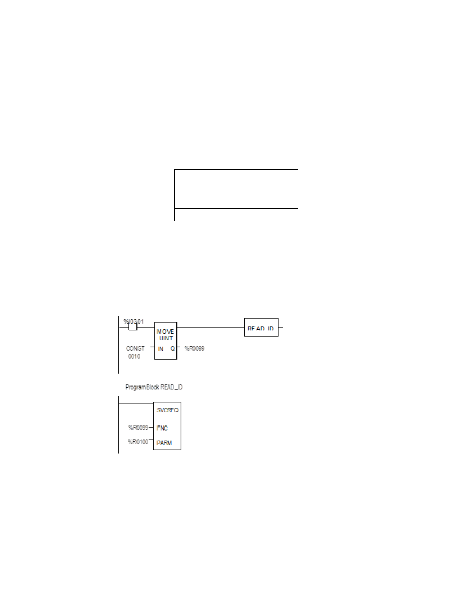
Example of SVCREQ 10  

In this example, when enabling input %I0301 goes OFF, register location %R0099 is loaded 
with the value 10, which is the function code for the Read Folder Name function.  The 
Program Block READ_ID is then called to retrieve the folder name.  The parameter block is 
located at address %R0100. 

Figure 357 


User Manual 

Chapter 24 

GFK-1645M 

Dec 2019 


Service Request Function 

515 

24.14


SVCREQ 11: Read PLC ID 

Use SVCREQ 11 to read the name of the PLC executing the program. 

24.14.1


Output Parameter Block Format for SVCREQ 11 

The output parameter block has a length of four words.  It returns eight ASCII characters; 
the last is a null character (00h). If the PLC ID has fewer than seven characters, null characters 
are added to the end.  


Low Byte 

High Byte  

address  

character 1 

character 2 

address + 1  

character 3 

character 4 

address + 2  

character 5 

character 6 

address + 3  

character 7 

00 

Example of SVCREQ 11  

In this example, when enabling input %I0302 goes OFF, register location %R0099 is loaded 
with the value 11, which is the function code for the Read PLC ID function.  The program 
block READ_ID is then called to retrieve the ID.  The parameter block is located at address 
%R0100. 

Figure 358 


User Manual 

Chapter 24 

GFK-1645M 

Dec 2019 


Service Request Function 

516 

24.15


SVCREQ 13: Shut Down (Stop) PLC 

Use SVCREQ 13 to stop the Micro PLC at the end of the next sweep.  All outputs go to the 

OFF state at the start of the next PLC sweep.  An informational “Shut Down PLC” fault

 is 

placed in the PLC Fault Table.  The I/O scan continues as configured. 

24.15.1


Parameter Block for SVCREQ 13 

This function has no parameter block.  

Example of SVCREQ 13 

In the example, when %T0001 is set SVCREQ 13 executes.  The PARM input is not used.  

This example uses a JUMP to the end of the program to force a shutdown if the Shutdown 
PLC function executes successfully.  This JUMP and LABEL are needed because the transition 
to Stop mode does not occur until the end of the sweep in which the function executes. 

Figure 359 


User Manual 

Chapter 24 

GFK-1645M 

Dec 2019 


Service Request Function 

517 

24.16


SVCREQ 14: Clear Fault 

Use SVCREQ 14 to clear either the PLC fault table or the I/O fault table.  The SVCREQ output 
is set ON unless some number other than 0 or 1 is entered as the requested operation. 

24.16.1


Input Parameter Block for SVCREQ 14 

For this function, the parameter block has a length of 1 word.  It is an input parameter block 
only. There is no output parameter block. 

0 = clear PLC fault table. 
1 = clear I/O fault table. 

Example of SVCREQ 14 

In  the  example,  when  input  %I0346  is  on  and  input  %I0349  is  on,  the  PLC  fault  table  is 
cleared.  When input %I0347 is on and input %I0349 is on, the I/O fault table is cleared.  When 
input %I0348 is on and input %I0349 is on, both are cleared.  A positive transition coil should 
be used to trigger SVCREQ14. 

The parameter block for the PLC fault table is located at %R0500; for the I/O fault table the 
parameter block is located at %R0550.  Both parameter blocks are set up elsewhere in the 
program. 

Figure 360 


User Manual 

Chapter 24 

GFK-1645M 

Dec 2019 


Service Request Function 

518 

24.17


SVCREQ 15: Read Last-Logged Fault Table 
Entry 

Use SVCREQ 15 to read the last entry logged in either the PLC fault table or the I/O fault 
table.  The SVCREQ output is set ON unless some number other than 0 or 1 is entered as the 
requested operation or the fault table is empty. 

24.17.1


Input Parameter Block for SVCREQ 15 

For this function, the parameter block has a length of 22 words.  The input parameter block 
has this format:  


2-Digit Year Format 

4-Digit Year Format 

address 

0 = Read PLC fault table. 

8 = Read PLC fault table. 


1 = Read I/O fault table. 

9 = Read I/O fault table. 

The format of the output parameter block depends on whether the function reads data from 
the PLC fault table or the I/O fault table. 

PLC Fault Table Output Format 


I/O Fault Table Output Format 

High Byte 

Low Byte 


High Byte 

Low Byte 


spare 

long/short 

address + 1 

memory type 

long/short 

spare 

spare 

address + 2 


offset 

slot 

rack 

address + 3 

slot 

rack 


task 

address + 4 

block 

bus 

fault action 

fault group 

address + 5 


point 


error code 

address + 6 

fault action  

fault group  


fault specific data 

address + 7 

fault type 

fault category 


address + 8 

fault specific data 

fault description 


to 


address + 18 


minutes 

seconds 

address + 19 

minutes 

seconds 

day of month 

hour 

address + 20 

day of month 

hour 


2-Digit Year 
Format  

year 

month 

address + 21 

year 

month 

or 

4-Digit Year   spare 

month 

address + 21 

spare 

month 

Format  

year 

address + 22 

year 


User Manual 

Chapter 24 

GFK-1645M 

Dec 2019 


Service Request Function 

519 

Long/Short Value 

The first byte of word address +1 contains a number that indicates the length of the fault-
specific data in the fault entry. These possible values are: 

PLC fault table 

00  =  8  bytes  (short) 
01 = 24 bytes (long) 

I/O fault table 

02  =  5  bytes  (short) 
03 = 21 bytes (long) 

Example of SVCREQ 15  

When inputs %I0250 and %I0251 are both on, the first Move function places a zero (read PLC 
fault table) into the parameter block for SVCREQ 15.  When input %I0250 is on and input 
%I0251 is off, the Move instruction instead places a one (read I/O fault table) in the SVCREQ 
parameter block. The parameter block is located at location %R0600. 

Figure 361 


User Manual 

Chapter 24 

GFK-1645M 

Dec 2019 


Service Request Function 

520 

24.18


SVCREQ 16: Read Elapsed Time Clock 

Use SVCREQ 16 to read the system's elapsed time clock. The elapsed time clock measures 
the time in seconds since the Micro PLC was powered on. 

24.18.1


Output Parameter Block for SVCREQ 16 

This function has an output parameter block only. Its length is 3 words. 

address 

seconds from power on (low order) 

address + 1 

seconds from power on (high order) 

address + 2 

100 µs ticks 

The first two words are the elapsed time in seconds. The last word is the number of 100 µs 
ticks in the current second. 

Example of SVCREQ 16 

In  the  example,  when  internal  coil  %M0233  is  on,  the  SVCREQ  with  a  parameter  block 
located at %R0127 reads the system's elapsed  time clock and sets internal coil %M0234.  
When coil %M0233 is off, the SVCREQ with a parameter block at %R0131 reads the elapsed 
time clock again. 

The subtraction function finds the difference between the first and second readings, which 
have been stored in the SVCREQ parameter blocks. The subtraction ignores the hundred 
microsecond ticks. 

The difference between the two readings is placed in memory location %R0250. 

Figure 362 


User Manual 

Chapter 24 

GFK-1645M 

Dec 2019 


Service Request Function 

521 

24.19


SVCREQ 18: Read I/O Override Status 

Use SVCREQ 18 to check for any overrides in the Micro PLC 's %I and %Q memories. 

24.19.1


Output Parameter Block for SVCREQ 18 

This function has an output parameter block only. Its length is 1 word. 

address 

0 = No overrides are set. 


1 = Overrides are set. 

Example of SVCREQ 18 

The following SVCREQ reads the status of I/O overrides memory into location %R1003.  The 
equality function checks %R1003 to see if it is equal to (the constant) 1. If it is, the equality 
function turns on output %T0001. 

Figure 363 


24.20


SVCREQ 23: Read Master Checksum 

Use  SVCREQ  23  to  read  the  master  checksums  of  the  application  program  and  the 
configuration. The SVCREQ output is always ON if the function is enabled. 

24.20.1


Output Parameter Block for SVCREQ 23 

For this function, the output parameter block has a length of 12 words with this format: 

The  first  two  items  in  the  output  parameter  block  indicate  when  the  program  and 
configuration  checksums  are  valid.  (Program  checksums  may  not  be  valid  during  a  Run 
Mode Store.) 

address 

Master Program Checksum Valid (0 = not valid, 1 = valid) 

address + 1 

Master Configuration Checksum Valid (0 = not valid, 1 = valid) 

address + 2 

Number of Program Blocks (including _MAIN) 

address + 3 

Size of User Program in Bytes (DWORD data type) 

address + 5 

Program Additive Checksum 

address + 6 

Program CRC Checksum (DWORD data type) 

address + 8 

Size of Configuration Data in Bytes 

address + 9 

Configuration Additive Checksum 

address + 10 

Configuration CRC Checksum (DWORD data type) 


User Manual 

Chapter 24 

GFK-1645M 

Dec 2019 


Service Request Function 

522 

Example of SVCREQ 23 

In the example, when input %I0251 is ON, the master checksum information is placed into 
the parameter block at %R0050 and the output coil (%Q0001) is turned on. 

Figure 364 


24.21


SVCREQ 26/ SVCREQ 30: Interrogate I/O 

Use SVCREQ 26 and SVCREQ30 to check whether the installed modules match the software 
configuration. If not, these SVCREQs place appropriate addition, loss, and mismatch faults 
in  the  PLC  and/or  I/O  fault  tables.  SVCREQ  26  and  SVCREQ  30  both  perform  the  same 
function. 

The  more  configuration  faults  there  are,  the  longer  it  takes  these  SVCREQs  longer  to 
execute. 

These SVCREQs have no parameter block. They always output power flow.   

Example of SVCREQ 26 

In the example, when input %I0251 is ON, the SVCREQ checks the installed modules and 
compares  them  to  the  software  configuration.    Output  %Q0001  is  turned  on  after  the 
SVCREQ is complete. 

Figure 365 


User Manual 

Chapter 24 

GFK-1645M 

Dec 2019 


Service Request Function 

523 

24.22


SVCREQ 29: Read Elapsed Power Down Time 

Use SVCREQ 29 to read the amount of time elapsed between the last power-down and the 
most recent power-up. If the watchdog timer expired before power-down, the PLC is not 
able to calculate the power down elapsed time, so the time is set to 0. 

The SVCREQ output is always ON. 

24.22.1


Output Parameter Block for SVCREQ 29 

This function has an output parameter block only. The parameter block has a length of 3 
words. 

address 

Power-Down Elapsed Seconds (low order) 

address + 1 

Power-Down Elapsed Seconds (high order) 

address + 2 

zero 

The first two words are the power-down elapsed time in seconds. The last word is always 0.   

Example of SVCREQ 29 

In the example, when input %I0251 is ON, the Elapsed Power-Down Time is placed into the 
parameter block that starts at %R0050. The output coil (%Q0001) is turned on. 

Figure 366 


24.23


SVCREQ 34: Enter Analog Calibration Mode 

The  final  step  of  calibrating  an  analog  channel  (see  the  complete  process  description  in 
Chapter 5:) consists of storing the calibration values in flash memory. This step requires the 
use of two SVCREQ functions, SVCREQ 34 and 35. 

SVCREQ 34 places the Micro PLC in calibration mode. When SVCREQ 34 is executed, the PLC 
uses  default  gain  and  offset  so  that  you  can  start  the  calibration  process.  No  parameter 
block is needed with SVCREQ 34.  

Note: 

This  calibration  procedure  applies  to  analog  channels  on  23-point  Micro  PLCs  only.   Software 
calibration of Analog Expansions and Nano PLCs is not available. 


User Manual 

Chapter 24 

GFK-1645M 

Dec 2019 


Service Request Function 

524 

Example of SVCREQ 34  

In the following example, when enabling input %I0251 goes ON, the analog calibration 
defaults are restored and output coil %Q0001 is turned on. 

Figure 367 


24.24


SVCREQ 35: Store Analog Calibration 

SVCREQ  35  stores  the  previously  computed  analog  calibration  in  the  Micro  PLC.  The 
calibration can be stored in either volatile or non-volatile memory. 

SVCREQ 35 uses an input parameter block containing the new calibration data and control 
data. Contents of the parameter block are shown on the next page. When the SVCREQ is 
successfully completed, the new calibration values take effect. 

After the SVCREQ function executes, the PLC returns the function status and the number of 
tries available to the 2 words of the output parameter block.  

Example of SVCREQ 35 

In the example, when contact %I0003 is on, the SVCREQ with a parameter block located at 
%R0127 stores the analog calibration to the memory type specified in the parameter block 
and sets coil %Q00234. 

Figure 368 


User Manual 

Chapter 24 

GFK-1645M 

Dec 2019 


Service Request Function 

525 

24.24.1


Input Parameter Block for SVCREQ 35 

The  input  parameter  block  for  SVCREQ  35  contains  the  following  32  input  words.  For 
parameter explanations, refer to Parameter Definitions below. 

Address 

Password (“CA” 4143H)


address + 1 

Password (“LB” 424CH)


address + 2 

Destination Control: 0 for RAM, 1 for flash 

address + 3 

Select Control AI Ch 1 Vol: 0: last, 1: new, 2: default, 3: factory 

address + 4 

Input Channel 1 %AI0018 High Value, Voltage  

address + 5 

Input Channel 1 %AI0018 Low Value, Voltage 

address + 6 

Input Channel 1 Meter High Value, Voltage (mV) 

address + 7 

Input Channel 1 Meter Low Value, Voltage (mV) 

address + 8 

Select Control AI Ch 1 Cur: 0: last, 1: new, 2: default, 3: factory 

address + 9 

Input Channel 1 %AI0018 High Value, Current  

address + 10 

Input Channel 1 %AI0018 Low Value, Current 

address + 11 

Input Channel 1 Meter High Value, Current (mA) 

address + 12 

Input Channel 1 Meter Low Value, Current (mA) 

address + 13 

Select Control AI Ch 2 Vol: 0: last, 1: new, 2: default, 3: factory 

address + 14 

Input Channel 2 %AI0019 High Value, Voltage 

address + 15 

Input Channel 2 %AI0019 Low Value, Voltage 

address + 16 

Input Channel 2-Meter-High Value, Voltage (mV) 

address + 17 

Input Channel 2 Meter Low Value, Voltage (mV) 

address + 18 

Select Control AI Ch 2 Cur: 0: last, 1: new, 2: default, 3: factory 

address + 19 

Input Channel 2 %AI0019 High Value, Current 

address + 20 

Input Channel 2 %AI0019 Low Value, Current 

address + 21 

Input Channel 2-Meter-High Value, Current (mA) 

address + 22 

Input Channel 2 Meter Low Value, Current (mA) 

address + 23 

Select Control AQ Ch 1 Vol: 0: last, 1: new, 2: default, 3: factory 

address + 24 

Output Channel 1 %AQ0012 High Value, Voltage 

address + 25 

Output Channel 1 %AQ0012 Low Value, Voltage 

address + 26 

Output Channel 1 Meter High Value, Voltage (mV) 

address + 27 

Output Channel 1 Meter Low Value, Voltage (mV) 

address + 28 

Select Control AQ Ch 1 Cur: 0: last, 1: new, 2: default, 3: factory 

address + 29 

Output Channel 1 %AQ0012 High Value, Current 

address + 30 

Output Channel 1 %AQ0012 Low Value, Current 

address + 31 

Output Channel 1 Meter High Value, Current (mA) 

address + 32 

Output Channel 1 Meter Low Value, Current (mA) 

address + 33 

Status 

address + 34 

Number of tries available 


User Manual 

Chapter 24 

GFK-1645M 

Dec 2019 


Service Request Function 

526 

24.24.2


Output Parameter Block for SVCREQ 35 

The output parameter block for SVCREQ 35 contains the following two output words: 

address 

Status 

address + 1 

Number of tries available 

Parameter Definitions 

Password (address and address +1) must be CALB. If an invalid password is provided, the 
service request returns error 3 in the status word. 

Destination Control (at address +2), determines whether to write the constants in flash or 
in RAM. You can select the RAM option (0) and calibrate as many times as necessary without 
burning the calibration constants into the flash memory. When you are satisfied with the 
calibration, you can select the flash option (1) and finalize the calibration. When the flash 
option  is  selected,  the  calibration  data  is  copied  into  RAM  as  well  as  burned  into  flash 
memory. It is important to issue a SVCREQ with the flash option selected in the Destination 
Control parameter field once the desired calibration state is reached. Otherwise, the new 
calibration values will be lost when the unit is powered off. 

Select Control (address +3). Allows you to calibrate a particular channel in a specific mode. 
Four choices are allowed for each channel: 

0: 

Last user calibration. The last calibration in flash is used for the channel and for the mode. (If 
no user calibration exists, the last factory calibration is used.) 

1: 

New. The PLC calculates new gain and offset using the values supplied in the next four words. 
New  calibration  value  will  replace  the  value  in  the  RAM  or  flash  as  determined  by  the 
Destination Control field. 

2: 

Default. If this option is specified, the default calibration value is used. 

3: 

Factory. If this option is specified, the last factory calibration value is used. 

Status (address +33). A status word is returned by the service request: 

1=Complete 

4=Not in calibration mode 

2=Out of tries 

5=Calibration values checksum bad 

3=Invalid password  6=Invalid calibration data 

Number of Tries Available (address +34). Indicates the number of tries remaining.  


User Manual 

Chapter 24 

GFK-1645M 

Dec 2019 


Service Request Function 

527 

24.25


SVCREQ 52: Read from Flash 

This Service Request is available with Release 3.0 and later Micro PLCs. 

Service  Request  52  reads  Reference  Variables  that  were  previously  written  into  flash 
memory using Service Request 53 and stores the variables in CPU reference memory.  Each 
execution of Service Request 52 can read: 


1 to 10 words of %R, %AI, or %AQ reference data. 


1 to 10 bytes of %I, %Q, %M, %T, or %G reference data. 

SVCREQ 52 uses an input parameter block containing the reference memory to be read. 
After  SVCREQ  52  executes,  the  PLC  returns  the  function  status  to  the  two  words  of  the 
output parameter block. 

Example of SVCREQ 52 

In this example, when enabling input %M0003 goes on, the Service Request reads the flash 
memory location specified in the Parameter Block located at %R00040 and places the data 
into the intended destination. It then sets coil %M0004. 

Figure 369 


User Manual 

Chapter 24 

GFK-1645M 

Dec 2019 


Service Request Function 

528 

24.25.1


Input Parameter Block for SVCREQ 52 

The input parameter block for SVCREQ 52 contains the following 5 input words. 

Address 

Memory type (number) of the flash memory location of the first byte or word of data 
to be read. Numbers are: 

Memory 

Decimal 

Hex 

%I (byte) 

16 

10 

%Q (byte) 

18 

12 

%T (byte) 

20 

14 

%M (byte) 

22 

16 

%G (byte) 

56 

38 

%R (word) 

08 

%AI (word) 

10 

0A 

%AQ (word) 

12 

0C 

address + 1  Offset of the requested data within the memory type in flash memory  

address + 2  Length of data to be read, 1 

 10 bytes or words. 

address + 3  Memory type of the PLC reference memory type where the requested data should be 

placed. See the numbers above. 

address + 4  Offset to place the requested data within the requested memory type in PLC reference 

memory.  

address + 5  Memory  type  of  the  PLC  reference  memory  type  for  the  completion  status.  

See the numbers above. For example, %R1 = memory type 8. 

address + 6  Offset in PLC Memory to write completion status (zero based).  

For example, %R1 = offset 0.  

24.25.2


Status Data for SVCREQ 52 

SVCREQ 52 returns one of the following status indications: 

Word 0 

Hex 

Dec  Status 

Definition 

0x0001 

Full Success 

All requested data was successfully read 

0x0101 

257 

Partial Success 

Less than requested data length was read. Can occur 
if all data requested was not present in flash. 

0x0102 

258 

Insufficient Dest Mem  Can occur if the PLC reference memory location 

specified is not sufficient to store all the data read 
from flash 

0x0202 

514 

Invalid Length 

Length is beyond minimum 1 and maximum 10 

0x0302 

770 

Source/Dest  
Mem Wrong 

Wrong source or destination reference memory 
specified in the SVCREQ. 

Word 1 

Number of bytes read 


User Manual 

Chapter 24 

GFK-1645M 

Dec 2019 


Service Request Function 

529 

24.26


SVCREQ 53: Write to Flash 

This Service Request is available with Release 3.0 and later Micro PLCs. 

Service Request 53 stores requested PLC reference data in flash memory.  Each execution of 
Service Request 53 can write: 


1 to 10 words of %R, %AI, or %AQ reference data. 


1 to 10 bytes of %I, %Q, %M, %T, or %G reference data. 

SVCREQ 53 uses an input parameter block containing the reference memory requested to 
be written. After SVCREQ 53 executes, the PLC returns the function status and the amount 
of user flash memory still available to the output parameter block. 

Example of SVCREQ 53 

In the example, when enabling input %M0003 goes on, the Service Request reads the PLC 
memory location specified in the Parameter Block located at %R00040 and writes the data 
to flash. It then sets coil %M0004. 

Figure 370 


Content      ..     33      34      35      36     ..