EMERSON PACSystems VersaMax MICRO PLC & NANO PLC. USER MANUAL (2019) - page 19
 

  Index      Manuals     EMERSON PACSystems VersaMax MICRO PLC & NANO PLC. USER MANUAL (2019)


Search            copyright infringement  


Content      ..     17      18      19      20     ..


EMERSON PACSystems VersaMax MICRO PLC & NANO PLC. USER MANUAL (2019) - page 19


User Manual 

Chapter 14 

GFK-1645M 

Dec 2019 


CPU Option Modules 

258 

MODBUS/TCP Function Codes Supported by VersaMax Micro PLCs 

Function 

Function 
Code 

Server Reference 
Memory Type 

Data Unit Size 

Comments 

Read Coils 

Coils 

Bit 

Read up to 2,000 bits 

Read Input 
Discrete 

Discrete Inputs 

Bit 

Read up to 2,000 bits 

Read Multiple 
Registers 

Register 

Register  
(16-bit word) 

Read up to 125 words  

Read Analog Input 
Registers 

Analog Input 
Registers 

Register  
(16-bit word) 

Read up to 125 words  

Write Coil 

Coil 

Bit 

Write one bit 

Write Single 
Register 

Register 

Register  
(16-bit word) 

Write one word 

Read Exception 
Status 

-NA- 

Byte 

-NA- 

Write Multiple 
coils 

15 

Coil 

Bit 

Write multiple bits, up 
to 2000 

Write Multiple 
Registers 

16 

Register 

Register  
(16-bit word) 

Write to a maximum 
of 100 words 

Status/Error Codes 

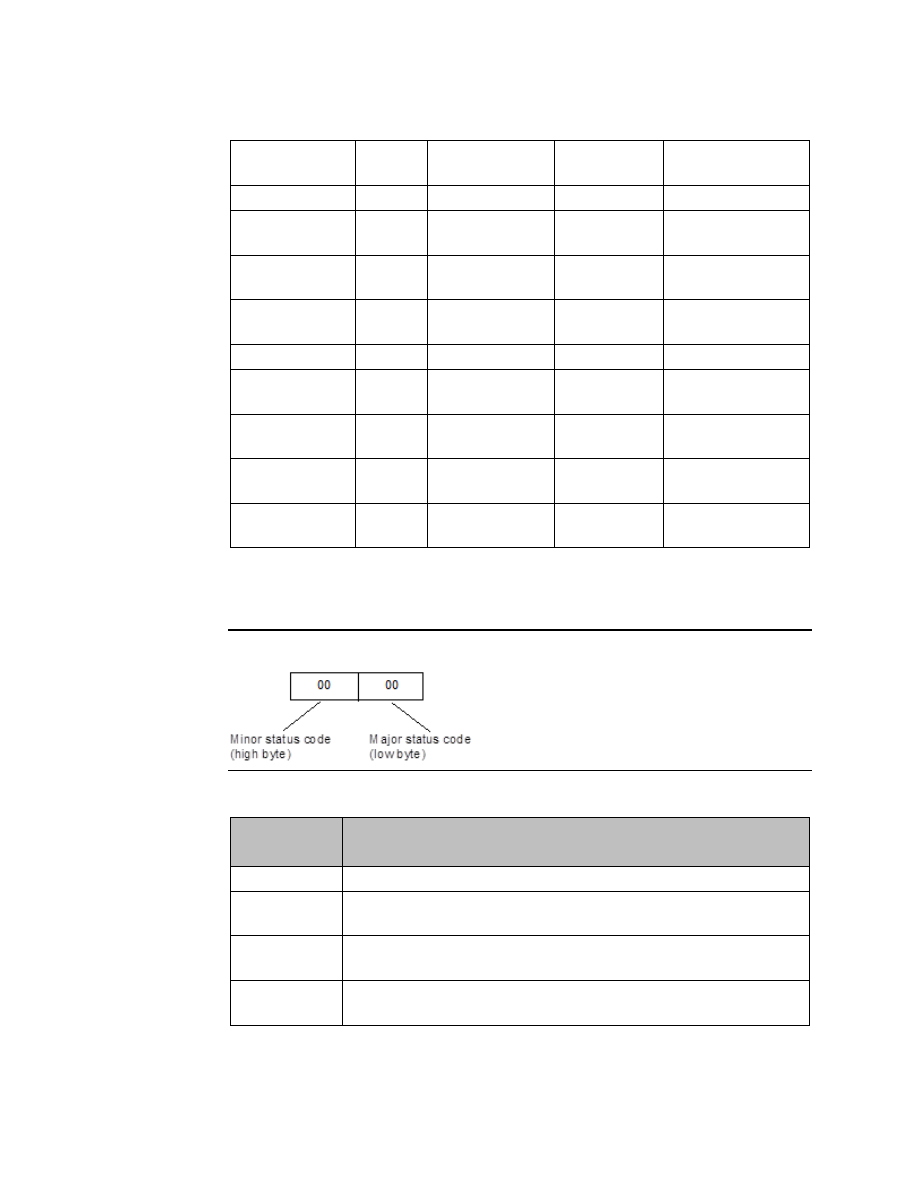
Status codes are reported in the following format: 

Figure 125 


Major Status Codes 

Error Status 
(Hex) 

Major Status Description 

01H 

Successful completion. No minor status code (value can be ignored.) 

91H 

Modbus TCP Status codes at the server. An error was detected at the Modbus 
TCP server. See the table on page 259 for the associated Minor Status Codes. 

B0H 

Client Application Error. See the table on page 259 for the associated Minor 
Status Codes. 

B1H 

Serial link error codes between Micro and Ethernet Module. See the table on 
page 261 for the associated Minor Status Codes. 


User Manual 

Chapter 14 

GFK-1645M 

Dec 2019 


CPU Option Modules 

259 

Minor Status Codes for Major Status 91H 

The following table lists minor status codes that can be reported for status code 91H, 
Remote Server Device error. 

Error Status 
(Hex) 

Error Description 

0191H 

Illegal Function. The function code received in the request is not allowed for the 
server. Causes may be: 
The function code is not implemented in the unit selected. For example, it may 
be a function that applies only to newer controllers. 
The server is in the wrong state to process a request of this type, for example 
because  it  was  not  configured  and  is  being  asked  to  return  register  status. 
Modbus exception code 01H. 

0291H 

Illegal data address. The data address received in the query is not an allowable 
address for the server. More specifically, the combination of reference number 
and transfer length is invalid. MODBUS exception code 02. 

0391H 

Illegal data value. A value contained in the query data field is not an allowable 
value  for  server.  This  indicates  a  fault  in  the  structure  of  the  remainder  of  a 
complex request, such as that the implied length is incorrect. It specifically does 
NOT mean that a data item submitted for storage in a register has a value outside 
the  expectation  of  the  application  program,  since  the  MODBUS  protocol  is 
unaware  of  the  significance  of  any  particular  value  of  any  particular  register. 
MODBUS exception code 03. 

0491H 

Slave  Device  Failure.  An  unrecoverable  error  occurred  while  the  server  was 
attempting to perform the requested action. 

0691H 

Slave Device Busy. Server service request queue full. MODBUS exception code 06. 

0791H 

Negative  Acknowledge.  Internal  server  error  occurred.  MODBUS  exception 
code 07  

Minor Status Codes for Major Status B0H 

The following table lists minor status codes that can be reported for status code B0H, 
Client Application Error. 

Error Status (Hex) 

Error Description 

85B0H 

Client device not yet ready to send the request. 

86B0H 

Server unit data size of zero is not allowed. The data unit size for 
read/write operations should be greater than zero. 

87B0H 

Server unit data size is too large. The data unit size for read/write 
operations should not cross the maximum value.  
Example: If the data length specified for Read/Write coil is greater than 
1, this error code is returned. 

88B0H 

Invalid Channel Number 

8BB0H 

This error will be triggered when the server reference memory address is 
zero, which is not allowed. 

User Manual 

Chapter 14 

GFK-1645M 

Dec 2019 


CPU Option Modules 

260 

Error Status (Hex) 

Error Description 

8CB0H 

Invalid  Client  Memory  Type.  This  error  is  triggered  when  the  specified 
client  reference  memory  type  is  invalid.  Refer  to  page  256  for  valid 
memory types. 

8EB0H 

Invalid IP address integer.  All four octets of the IP address should be in the 
range 0 to 255.  

8FB0H 

Invalid IP address class. 

90B0H 

Insufficient TCP connection resources to perform request.  

91B0H 

Zero  local  starting  address  is  not  allowed,  The  starting  address  of  the 
client PLC memory location should be greater than zero. 

95B0H 

Internal Error. This problem may occur due to the Ethernet Interface being 
asked to perform beyond its capacity. 

96B0H 

Underlying  TCP  connection  aborted  (reset)  by  server  end  point.  The 
server is not responding within the timeout value. 

97B0H 

Underlying TCP connection aborted (reset) by Client end point. 

9CB0H 

Invalid frame format. Data response did not arrive in a proper order. 

9DB0H 

Data response had unexpected size. For example received more data than 
expected. 

9FB0H 

Invalid Client PLC Memory reference address. 

B6B0H 

Unrecognized  Function  code.  The  Client  device  does  not  support  the 
function code or operation. 

B7B0H 

Invalid Unit Identifier. 

A0B0H 

Invalid Server Reference Memory Address. 

A2B0H 

Failed  to  update  the  Micro  reference  memory.  Ethernet  Module  was 
unable to write to the Client memory specified in the command data. 

A7B0H 

Unable  to  connect  to  remote  device  after  successful  channel 
establishment. 

AAB0H 

An attempt to establish a TCP connection with a remote server failed. This 
error can be caused by the following conditions: 
Server is not turned on 
Cables are not properly connected 
If using a switch, switch is not turned on 
This  error  can  occur  while  establishing  the  connection  with  the  server 
device. 

ACB0H 

A protocol error occurred while communicating with the local PLC. This 
error can occur when a break in the frame or check sum error occurred. 

ADB0H 

A TCP timeout occurred while communicating with the remote PLC. 


User Manual 

Chapter 14 

GFK-1645M 

Dec 2019 


CPU Option Modules 

261 

Minor Status Codes for Major Status B1H 

The following table lists the minor status codes that can be reported for the major status 
code B1H, which indicates a Serial Link error in the communications between the Ethernet 
module and the Micro PLC. 

If communication between the Ethernet Module and the Micro CPU is not functional, the 
Ethernet  Module  indicates  the  problem  by  LED  blink  patterns  and  through  the  TELNET 
connection. If the error codes reported by the Ethernet Module, by LEDs or through TELNET, 
are different, the Serial Link error code has the highest priority.  

Error Status (Hex) 

Error Description 

01B1H 

Unable to read the Sequence Number Data Structure. 

02B1H 

Unable to read the Command Data Structure 

03B1H 

Unable to read/write Client PLC reference memory (segment 
selector/offset specified in command data structure). 

04B1H 

Unable to update the response status/sequence number  

05B1H 

Serial Communication error (Parity, Baud rate, framing, Over run etc.) 
with the Micro CPU. 

Examples for MODBUS_TCP_RW 

For the following examples: 

1.


The IP address is stored as integer values in the four words starting at %R1001. 

Figure 126 


2.


When %I00488 is on, the MODBUS_TCP_RW function block is executed on the 
rising transition of %T0001. For parameter definitions, refer to page 256. 

User Manual 

Chapter 14 

GFK-1645M 

Dec 2019 


CPU Option Modules 

262 

Function 

Sample Rung 

Reading Coils (FC=1) 
Reads a coil at offset 10 
(RMO=10) in the remote Modbus 
TCP server and store the value at 
the location %Q10 (LMR=72, 
LMO=10).  


Reading Discrete Inputs (FC=2) 
Read nine discrete inputs from 
offset 5 (RMO=5) in the remote 
Modbus TCP server and store the 
values in bit mode at %Q3 
(LMR=72, LMO=3). 


User Manual 

Chapter 14 

GFK-1645M 

Dec 2019 


CPU Option Modules 

263 

Function 

Sample Rung 

Reading Multiple Registers (FC=3) 
Read 125 registers from the 
remote server device. The 
Remote server reference address 
is %R0101 (LMR=8, LMO=101). 
The Client or Local PLC reference 
memory address is %R5001 
(LMR=8, RMO=5001). 


Reading Analog Inputs (FC=4) 
Read nine analog input registers 
at offset 200 (RMO=200) in the 
remote Modbus TCP device and 
store the values in the Client PLC 
memory location %R0020 
(LMR=8, LMO=20).  


User Manual 

Chapter 14 

GFK-1645M 

Dec 2019 


CPU Option Modules 

264 

Function 

Sample Rung 

Writing a Coil (FC=5) 
Write the value at %Q4 (LMR=72, 
LMO=4) in the Client PLC memory 
location to coil %Q5 (RMO=5) in 
the remote Modbus TCP device.  


Writing a Single Register (FC=6) 
Write one register from %R10 
(LMR=8, LMO=10) to a holding 
register at offset 200 (RMO=200) 
in the remote Modbus TCP 
server.  


User Manual 

Chapter 14 

GFK-1645M 

Dec 2019 


CPU Option Modules 

265 

Function 

Sample Rung 

Reading Status (FC=7) 
Read the Status from the remote 
Modbus TCP server and store the 
Status data in bit mode at 
location %Q4 (LMR=72, LMO=4).  


Writing Multiple Coils (FC=15) 
Write the eight values starting 
from %Q1 (LMR=72, LMO=1) in 
the Client reference memory to 
eight coils starting at offset 1 
(RMO=1) in the Remote Modbus 
TCP device. 


User Manual 

Chapter 14 

GFK-1645M 

Dec 2019 


CPU Option Modules 

266 

Function 

Sample Rung 

Writing Multiple Registers 
(FC=16) 
Write 100 registers from the 
Client reference memory address 
%R5001 (LMR=8, LMO=5001) to 
the remote server reference 
address %R101 (RMO=101). 


14.6.8


Security Settings for the Ethernet Option Module 

Security  settings  can  be  changed  to  prevent  unauthorized  entry  into  Ethernet  Option 
Module configuration mode. 

Two security settings are supported for the Ethernet Option Module (firmware version 2.0 
and  later):  Password  support  for  Telnet  configuration  and  SNMP  (Enable/Disable) 
configuration. 

Security  settings  are  provided  for  the  three  protocols:  SNP/SRTP,  Modbus  TCP  and 
Tunneling.  

For  Modbus  TCP  and  SRTP  protocols,  these  security  settings  options  are  present  in  the 
"Network/IP Settings" menu for. For Tunneling (Pass-through), these security settings are 
present in the "basic parameters/server" menu. 

By  default,  there  is  no  password  and  Simple  Network  Management  Protocol  (SNMP)  is 
enabled. 

Disabling or Enabling the SNMP is configurable. 

The maximum password length is 16 characters. These characters can be alphanumeric or 
special characters. The password requires a minimum length of 8 characters. 

A  password  set  on  a  particular  protocol’s  firmware  remains  i

n  effect  if  the  firmware  is 

changed to that of a different protocol. For example, if a password is set on Modbus TCP 
firmware and later the firmware is changed to SNP/SRTP, the same password set on Modbus 
TCP firmware will still apply. 

User Manual 

Chapter 14 

GFK-1645M 

Dec 2019 


CPU Option Modules 

267 

If the password is set, it will be required before entering to the Telnet configuration Setup 
Mode. After prompting for password, if the password is not entered within 30 seconds, the 
Telnet session will expire. 

14.7


Installing Option Modules 

CAUTION 

Power to the VersaMax Micro PLC MUST BE TURNED OFF when installing or removing 
Option Modules. 

1.


Access the option connector on the front of the unit, as shown below for a Micro-
64 PLC. 

Figure 127 


2.


If a port-type Option Module is being installed, orient the connector on the Option 
Module with the connector in the Micro PLC. Be careful to avoid contact with the 
exposed components in the module. 

Figure 128 


3.


Press the Option Module downward until it clicks into place. 

4.


Install the screws provided with the Option Module into the corners as shown 
above. 


User Manual 

Chapter 14 

GFK-1645M 

Dec 2019 


CPU Option Modules 

268 

Figure 129 


5.


If a Memory Pack Module is being installed, orient the connector on the back of the 
Memory  Pack  Module  with  the  connector  on  the  Micro  PLC  or  port-type  Option 
Module. Press the Memory Pack Module downward until it clicks into place.  

6.


Install the protective cover(s). If only the Memory Pack Module is used, both covers 
may be installed. If a port module is used, the right-hand cover is not installed, and 
the port connector remains accessible.  


User Manual 

Chapter 15 

GFK-1645M 

Dec 2019 


Installation Instructions 

269 

Chapter 15:


Installation Instructions 

This chapter describes the procedures for installing a VersaMax Nano PLC or VersaMax Micro 
PLC  and  preparing  the  system  for  use.  Included  in  this  chapter  are  instructions  for 
unpacking, inspecting, and installing the PLC. Instructions are also provided for connecting 
cables to programming devices.  


Pre-installation check 


Agency Approvals, Standards, and General Specifications 


Immunity and Emission Specifications, Relevant Standards, and Level Passed 


Installation Guidelines 


Mounting Dimensions 


Grounding the Equipment 


Installing a PLC or Expansion Unit on a DIN Rail 


Connecting an Expansion Unit to a Micro PLC 


System Wiring Guidelines 


Starting Up the PLC 


Adjusting the Analog Potentiometers 


DIP Switches 


Installing/Replacing a Backup Battery 


Serial Port Connections 


RS485 Port Isolator 


RS-232 to RS-485 Adapter 


Replacing AC Output Module Fuses 

15.1


Preinstallation Check 

Carefully  inspect  all  shipping  containers  for  damage  during  shipping.  If  any  part  of  the 
system  is  damaged,  notify  the  delivery  service  immediately.  The  damaged  shipping 
container  should  be  saved  as  evidence  for  inspection  by  the  delivery  service.  As  the 
consignee, it is your responsibility to register a claim with the delivery service for damage 
incurred  during  shipment.  However,  Emerson  will  fully  cooperate  with  you,  should  such 
action  be  necessary.  After  unpacking  the  equipment,  record  all  serial  numbers.  Serial 
numbers are required if you should need to contact Product Service during the warranty 
period of the equipment. All shipping containers and all packing material should be saved 
should it be necessary to transport or ship any part of the system. 

Keep Micro PLC modules in their boxes during storage and transport. 


User Manual 

Chapter 15 

GFK-1645M 

Dec 2019 


Installation Instructions 

270 

15.2


Agency Approvals, Standards, and General 
Specifications  

The  Micro  PLC  products  supplied  by  Emerson  are  global  products  designed  and 
manufactured  for  use  throughout  the  world.  They  should  be  installed  and  used  in 
conformance  with  product-specific  guidelines  as  well  as  the  following  agency  approvals, 
standards and general specifications:  

Agency Approvals 


Comments 

Industrial Control Equipment 
[Safety] 

UL508,  
CSA C22.2 No 142-M1987 

Certification by Underwriters 
Laboratories for Revision B and later 
models 

Hazardous Locations [Safety] 
Class I, Div II, A, B, C, D 

UL1604 
CSA C22.2 No 142-M1987 

Certification by Underwriters 
Laboratories for Revision B and later 
models 

European EMC & LVD 
Directives 

CE Mark 

All models 


Environmental  


Conditions 

Vibration 

IEC68-2-6, JISC0911 

1G @57-500Hz, 0.15mm p-p @10-
57Hz  

Shock 

IEC68-2-27, JISC0912  

15G, 11ms 

Operating Temperature 


0°C to 55°C [ambient] 

Storage Temperature 


10°C to +75°C 

Humidity 


5% to 95%, non-condensing 

Enclosure Protection 

IEC529 

Enclosure per IP54; protection from 
dust & splashing water 

Isolation: Dielectric 
Withstand 

UL508, UL840, IEC664 

1.5kV for modules rated from 51V to 
250V 


User Manual 

Chapter 15 

GFK-1645M 

Dec 2019 


Installation Instructions 

271 

15.2.1


Immunity and Emission Specifications, Relevant 
Standards, and Level Passed 

Description 

Standards 

Specifications 

Electrostatic Discharge 

EN 61000-4-2 

 4.0 kV (Contact); 

 8.0 kV (Air) 

RF Susceptibility 

EN 61000-4-3 

10 V/m (unmodulated), 80-1000 MHz, 80% AM,  
1 kHz sine wave 

RF Susceptibility from 
Digital Radio Telephones 

ENV 50204 

10 V/m (unmodulated), 900

5MHz, 100% AM (200 

Hz square wave, 50% duty cycle) 

Fast Transient 

EN 61000-4-4 

 2.2 kV (PS);  

 1.1 kV (I/O) 

Voltage Surge 

EN 61000-4-5 

 2.2 kV, common mode (PS) 

 1.1 kV, differential (PS) 

Conducted RF 

EN 61000-4-6 

10 Vrms, 0.15-80 MHz, 80% AM, 1 kHz sine wave 
(PS, I/O) 

Voltage Dip 
Voltage Interrupt 
Voltage Variation 

EN 61000-4-
11 

30% Nom., 10 ms 
>95% Nom., 10ms 
20% Nom., 10 sec. 

Radiated Emissions 

EN 55011 

8


30 dB

V/m, 30 

 230 MHz (measured @ 30m) 

37 dB

V/m, 230 

 1000 MHz (measured @ 30m) 

Conducted Emissions 

EN 55011

8


79/66 dB

V, 0.15 

 0.5 MHz 

73/60 dB

V, 0.5 

 30 MHz 

15.3


Installation Guidelines 


This  equipment  is  intended  for  use  in  typical  industrial  environments  that  utilize 
anti-static materials such as concrete or wood flooring. If the equipment is used in 
an  environment  that  contains  static  material  such  as  carpets,  personnel  should 
discharge themselves by touching a safely grounded surface before accessing the 
equipment. 


If the AC mains are used to provide power for I/O, these lines should be suppressed 
prior to distribution to the I/O so that immunity levels for the I/O are not exceeded. 
Suppression  for  the  AC  I/O  power  can  be  made  using  line-rated  MOVs  that  are 
connected  line-to-line,  as  well  as  line-to-ground.  A  good  high-frequency  ground 
connection must be made to the line-to-ground MOVs. 


Installation should be indoors with primary facility surge protection on the incoming 
AC power lines. 


8


EN 55011 limits are equivalent to limits specified in EN 55022, CISPR 11, CISPR 22, and 47 CFR 15. 

User Manual 

Chapter 15 

GFK-1645M 

Dec 2019 


Installation Instructions 

272 

15.3.1


CE Mark Installation Requirement 

For compliance to the Low Voltage Directive, VersaMax Nano and VersaMax Micro systems 

are considered ‘open equipment’ (i.e. live electrical parts may be accessible to us

ers) and 

must  be  installed  in  an  enclosure.  IEC  1131-

2:1991  (sect.  4.2,  item  2)  states:  “Open 

equipment is not required to meet IP2x requirement…. Opening of the enclosure shall only 
be possible by means of a key or tool.”  The PLC equipment should be inst

alled in a location 

that meets the specifications listed on the previous page.  

15.3.2


UL Requirements for Class I Div 2 Installations 

Equipment labeled with reference to Class 1 Div. 2 Groups A, B, C & D,  hazardous locations 
is suitable for use in Class 1, Division 2, Groups A, B, C, D or non-hazardous locations only. 

Equipment labeled with reference to Class 1 Zone 2 Groups A, B, C & D, hazardous locations 
is suitable for use in Class 1, Zone 2, Groups A, B, C, D or non-hazardous locations only. 

 WARNING 


Explosion hazard - substitution of components may impair suitability for Class 1, 
Division 2. 


Explosion hazard - do not disconnect equipment unless power has been switched off 
or the area is known to be non-hazardous. 


15.3.3


Additional Environmental Guidelines 


The temperature must not change so rapidly that condensation could form on or 
inside the unit. 


There should be no combustible, corrosive or flammable gases. 


The environment should not have excessive dust, salty air, or conductive materials 
(iron powder, etc.) that could cause internal shorts. 


The PLC should not be installed where it will be exposed to direct sunlight.  


The PLC should not be exposed to water, oil or chemicals. 


Provide adequate ventilation space. Recommended minimum space allowances are 
approximately: 50mm (2 inches) top, sides and bottom.  


The PLC should not be installed above equipment that generates a large amount of 
heat. 


If  the  ambient  temperature  exceeds  55°C,  provide  a  ventilation  fan  or  air 
conditioner. 


The equipment should not be installed within 200mm (8 inches) of any high voltage 
(more  than  1000V)  or  high  current  (more  than  1A)  line  (except  for  outputs 
controlled by the PLC). 


For ease of maintenance and safety, locate the PLC equipment as far away from high 
voltage equipment and power generation equipment as possible.  

User Manual 

Chapter 15 

GFK-1645M 

Dec 2019 


Installation Instructions 

273 


Take appropriate measures when installing systems in locations: 


subject to static electricity or other forms of noise. 


subject to strong electromagnetic fields. 


close to power supplies. 

15.4


Mounting Dimensions 

15.4.1


Dimensions of Nano PLCs 

Figure 130 


Content      ..     17      18      19      20     ..