EMERSON PACSystems VersaMax MICRO PLC & NANO PLC. USER MANUAL (2019) - page 18
 

  Index      Manuals     EMERSON PACSystems VersaMax MICRO PLC & NANO PLC. USER MANUAL (2019)


Search            copyright infringement  


Content      ..     16      17      18      19     ..


EMERSON PACSystems VersaMax MICRO PLC & NANO PLC. USER MANUAL (2019) - page 18


User Manual 

Chapter 13 

GFK-1645M 

Dec 2019 


RTD and Thermocouple Expansion Units 

242 

13.5.4


High-Resolution Temperature Conversion Logic for 
Thermocouple Units 

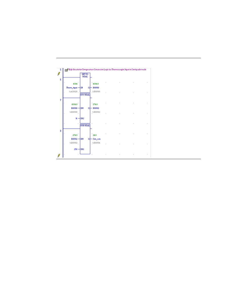
For accuracy in tenths of degrees, the Data Type Conversion functions (see Chapter 23:) can 
be added to the program logic. See the examples (for the Compatible mode) below. 

Figure 111 


Celsius Conversion 

Line 6: Converts thermocouple input to Real Value.  Data will be stored in two consecutive 
Registers 100 and 101 

Line 7: Divides the raw value by 16.0 ((32160-8)/ 2009.5). 

The value 2009.5 comes from the full temperature range of 1760 to 

249.5 C.  Result is 

placed in R102 and R103 

Line 8: Subtracts 250 for conversion. This is to offset the 

250 and the result is in R104 and 

R105 


User Manual 

Chapter 13 

GFK-1645M 

Dec 2019 


RTD and Thermocouple Expansion Units 

243 

Figure 112 


Fahrenheit Conversion 

Line 10: Converts thermocouple input to Real Value.  Data will be stored in two consecutive 
Registers 200 and 201 

Line 11: Divides the raw value by 8 ((30464-8)/ (3807))  

The value 3807 comes from the full temperature range of 3308 to 

449 F.  Result is placed 

in R202 and R203 

Line 12: Subtracts 500 for conversion.  This is to offset the 

500 and the result is in R204 and 

R205 


User Manual 

Chapter 14 

GFK-1645M 

Dec 2019 


CPU Option Modules 

244 

Chapter 14:


CPU Option Modules 

This chapter describes option modules for 20, 40 and 64-Point VersaMax Micro PLCs. 

IC200UMB001 

Memory Pack Module 

IC200USB001 

RS232, Extra Port Option Module  

IC200USB002 

RS485, Extra Port Option Module  

IC200UUB001 

USB/RS232 Conversion Option Module  

IC200UEM001 

10/100 Mbit Ethernet Communications Module 

14.1


Using Option Modules 

Option Modules can be used to enhance the functionality of a 20-, 40-, or 64-Point VersaMax 
Micro PLC. These option modules install in the front of the Micro PLC.  One Port module 
(UEM001, USB001, USB002, or UUB001), and/or a Memory Pack module (UMB001) can be 
installed. 

Option  modules,  except  the  Memory  Pack  Module,  are  configured  using  the  Machine 
Edition software. The Memory Pack Module does not require software configuration. If the 
configuration and installed option modules are different, the PLC logs a fault in the Fault 
Table (System Configuration Mismatch). 

Note: 

If the configured module is RS232/USB and the physically connected module is Ethernet 
communication module (upon downloading configuration), a system configuration mismatch 
fault will not be logged. The converse is also true. 

14.2


IC200UMB001 
Memory Pack Module 

The VersaMax Micro PLC Memory Pack Module, IC200UMB001, can be used to store and 
update the configuration, application program, and reference table data of a 20, 40, or 64-
Point Micro PLC.   

Figure 113 


The Memory Pack Module plugs directly into port 2 on the Micro PLC. Power for the device 
comes from port 2.  

A programmer and PLC CPU are used to initially write data to the Memory Pack Module. In 
addition to writing data to the Memory Pack, the programmer can read data already stored 
on  the  Memory  Pack  and  can  compare  that  data  with  files  already  present  in  the 
programmer. 

User Manual 

Chapter 14 

GFK-1645M 

Dec 2019 


CPU Option Modules 

245 

After the data is stored on the Memory Pack, the data can be copied to one or more other 
PLC CPUs of the same  type, with  no programmer needed. To do that, the Memory Pack 
Module is removed from the Micro PLC, and installed on another Micro PLC (Micro PLCs must 
be powered down to remove or install an option module). When the second Micro PLC is 
powered  up,  all  of  the  data  on  the  Memory  Pack  is  written  into  the  corresponding  PLC 
reference addresses. 

14.2.1


Features 


Store 128kB of data. 


Read the data at Power up. 


Read/Write/Verify the data through programmer command. 

With  the  programmer  present,  the  PLC  CPU  can  read,  write,  or  verify  a  program, 
configuration and tables in the Memory Pack Module. When reading or verifying data, it is 
possible  to  select  hardware  configuration,  logic,  and/or  reference  tables  data.  However, 
when  writing  data  to  the  Memory  Pack  Module,  all  the  data  (logic,  configuration  and 
reference tables) must be written. Individual data types cannot be selected for writing. 

Reading Data from the Memory Pack Module at Startup 

If the Memory Pack Module is connected to the port 2 when the PLC is switched on, the PLC 
automatically reads all the data (program, configuration, and tables) in the Memory Pack 
Module. The Micro PLC stores the data in its RAM/FLASH and flash based on the options that 
have been set in the hardware configuration. 

The  OK  LED  keeps  blinking  while  the  data  is  being  transferred  from  the  Memory  Pack 
Module to the PLC. Wait until the OK LED stops blinking to do any further operations. 

Data Read, Write, Verify Operations Using the Programming 
Software 

Read/Write/Verify  operations  can  be  done  on  the  Memory  Pack  Module  using  the 
programming software. The PLC must be placed in Stop mode. 

The path for write /read/ verify through programming software is: 

Targets -> online commands -> Flash/EEPROM  

The popup window for write/read/verify appears. Select the memory storage board option 
from the two choices (memory storage board or flash memory) to transfer data between 
the Memory Pack module  and the CPU. Then select the write/read/verify operation. The 
programming software shows the status of the data transfer. 

The Memory Pack Module and PLC must both have either no OEM key password or the same 
OEM  key  password  for  the  data  to  be  transferred.  The  Memory  Pack  Module  does  not 
perform special processing for other type of passwords. 


User Manual 

Chapter 14 

GFK-1645M 

Dec 2019 


CPU Option Modules 

246 

Write Protect Switch 

Figure 114 


The Write Protect switch on the Memory Pack Module prevents writing data to the module 
when it is in the ON position.   

CAUTION 

If the Write Protect switch is in ON position and the programming software tries to write 
data to the Memory Pack Module, the data is NOT written to the module. However, no error 
message is generated, and there is no indication that the data has not been written.  This 
should be considered before setting the Write Protect switch. 

14.3


IC200USB001 
RS232 Extra Port Option Module with 2 Analog 
Inputs 

VersaMax Micro PLC Option Module IC200USB001 can be used with a 20, 40, or 64-Point 
Micro PLC to provide an extra RS232 Port and two analog inputs. 

Figure 115 


When installed on the Micro PLC, the RS232 Port Option Module becomes port 2. It supports 
the following communications protocols: 


Modbus Master/Slave 


Serial Read/Write 


SNP/SNPX Master/Slave 

Use of the Port Option module as port 2, and the protocol selection must be set up in the 
configuration  software.  After  making  those  selections,  the  communications  parameters 
can also be configured. 


User Manual 

Chapter 14 

GFK-1645M 

Dec 2019 


CPU Option Modules 

247 

Pin assignments for Port 2 are 

Figure 116 


An external device can obtain power from the 5Vdc output pin if it requires 200mA or less 
at 5Vdc. 

14.3.1


Analog Inputs 

The terminals on the Port Option Module can be used for analog inputs with the following 
characteristics: 

Input Ranges  

0-10 V (10.24 V Max)  

Resolution  

0-10 V, 10 bits  

Accuracy  

±1%  

Linearity  

±3 LSB Maximum  

Voltage Input Impedance  

100kΩ


Isolation 

Channel to channel: none 
CPU to analog signal: none 

Analog Terminal Wiring 

Solid wire: 0.14mm2 to 1.5mm2 
Stranded wire: 0.14mm2 to 0.10mm2 

Figure 117 


User Manual 

Chapter 14 

GFK-1645M 

Dec 2019 


CPU Option Modules 

248 

14.4


IC200USB002 
RS-422/485 Extra Port Option Module with 2 
Analog Inputs 

VersaMax Micro PLC Option Module IC200USB002 can be used with a 20, 40, or 64-Point 
Micro PLC to provide an extra RS-422/485 Port and two analog inputs. 

Figure 118 


When installed on the Micro PLC, the RS-422/485 Port Option Module becomes port 2. It 
supports the following communications protocols: 


Modbus Master/Slave 


Serial Read/Write 


SNP/SNPX Master/Slave 

Use of the Port Option module as port 2, and the protocol selection must be set up in the 
configuration  software.  After  making  those  selections,  the  communications  parameters 
can also be configured. 

Pin assignments for Port 2 are: 

Figure 119 


An external device can obtain power from the 5Vdc output pin if it requires 200mA or less 
at 5Vdc. 


User Manual 

Chapter 14 

GFK-1645M 

Dec 2019 


CPU Option Modules 

249 

14.4.1


Analog Inputs 

The terminals on the Port Option Module can be used for analog inputs with the following 
characteristics: 

Input Ranges  

0-10 V (10.24 V maximum  

Resolution  

0-10 V, 10 bits  

Accuracy  

±1%  

Linearity  

±3 LSB Maximum  

Voltage Input Impedance  

100kΩ


Isolation 

Channel to channel: none 
CPU to analog signal: none 

Analog Terminal Wiring 

Solid wire: 0.14mm2 to 1.5mm2 
Stranded wire: 0.14mm2 to 0.10mm2 

Figure 120 


14.5


IC200UUB001  
USB / RS232 Conversion Option Module 

VersaMax Micro PLC Option Module IC200UUB001 can be used with a 20, 40, or 64-Point 
Micro PLC to provide a USB Port. 

Figure 121 


Characteristics of the USB Port are: 

Connector  

Straight B type  

USB version  

2.0  

Power   

Self-powered  

Baud Rates 
Supported 

4800 through 38400 only.  
Do not configure other baud rates for Port 2 when using the USB Conversion 
Option Module. 


User Manual 

Chapter 14 

GFK-1645M 

Dec 2019 


CPU Option Modules 

250 

Connecting  to  the  USB  board  from  windows  should  automatically  download  the  correct 
driver from Microsoft. To download directly, go to 

http://www.ftdichip.com/Drivers/FT232-

FT245Drivers.htm


14.6


IC200UEM001 
RJ-45,  10/100  Mbit  Ethernet  Communications 
Module 

The VersaMax Micro PLC Option Module IC200UEM001 can be used with a Micro 20, 40, or 
64-Point PLC to provide an Ethernet Port. 

Figure 122 


When installed on the PLC, the Ethernet Port Option Module becomes Port 2. It supports the 
following communications protocols:  


SRTP Server 


Modbus Server/Client (separate download) 


Pass- through port (separate download). 

Protocol options are available o

https://www.emerson.com/Industrial-Automation-

Controls/support


14.6.1


Module Specifications 

Processor Speed 

DSTni-EX CPU, 48MHz 

Memory 

256 kByte RAM, 512 kByte FLASH 

Connection Type 

RJ 45 10Base-T/100Base-TX Ethernet 

Entity Type 

Server/Client 

Bus Speed 

10/100Mbaud 

Number of Connections 
Supported 

Supports up to 8 TCP/IP connections (4 for SRTP, 8 for Modbus 
TCP, 1 for Tunneling) 

Mode 

Full Duplex 


User Manual 

Chapter 14 

GFK-1645M 

Dec 2019 


CPU Option Modules 

251 

14.6.2


Status LEDs 

Link LED (Amber) 

Solid Amber: Connection to Micro 64 established and network is connected 

Activity (Green) 

Flashing Green when there is any activity on the network 

Status (Red) 

OFF: No errors 
Red ON: Duplicate IP address present or network controller error 
Red BLINK (2x/sec): No DHCP response or Setup menu active 

14.6.3


Configuration Options 

The option port should be configured for Ethernet. Configuration options are: 

Protocol 

Parameters 

Value 

SRTP Server 

Port Mode 

SNP 

Port Type 

Slave 

Data Rate 

19.2, 38.4 or 175.0 kbps (default) 

Flow Control 

None 

Parity 

Odd (default), Even, None 

Stop bits 

1 (default), 2 

Time Out 

Long 

Turnaround Time 

Modbus TCP Client/Server 

Port Mode 

RTU  

Port Type 

Slave 

Data Rate 

19.2, 38.4 or 175.0 kbps (default) 

Flow Control 

None 

Parity 

Odd (default), Even, None 

Station Address 

0

247. Default = 1. 

Modbus/TCP Client 
Support (see page 252). 

Disabled (default) or Enabled.  
Enabling Modbus/TCP Client Support 
sets the %I00488 status bit ON. 

Pass-Through or Tunneling 

Port Mode 

Serial I/O 

Data Rate 

19.2, 38.4 or 175.0 kbps (default) 

Flow Control 

None 

Parity 

Odd (default), Even, None 

Stop bits 

1 (default), 2 

Bits/Characters 

7 or 8 

Station Address  
(Byte 1 to Byte 8) 

0 (default) 

FF 

For detailed information on the Telnet configuration of the Ethernet Option Module for 
each protocol, refer to GFK-2436E or later. 


User Manual 

Chapter 14 

GFK-1645M 

Dec 2019 


CPU Option Modules 

252 

14.6.4


Enhanced Data Throughput 

The  versions  3.83  of  Micro  and  later,  and  versions  2.0  and  later  of  the  Ethernet  Option 
Module firmware provide Enhanced Data Throughput on Port 2 with the Ethernet Option 
Module. 


Data rates supported for the Ethernet Option Module are: 19,200bps, 38,400bps 
and 175,000bps. Firmware releases 3.82 and earlier supported data rates 300bps 
through 38400 on Ethernet Module. Release 3.83 and later do not support 300bps 
through 9,600bps data rates, but support for a higher data rate of 175,000bps is 
added. 


The default baud rate for Port 2 with the Ethernet Option module is 175000bps. This 
is  the  baud  rate  for  which  the  Micro  Port  2  will  be  configured  during  auto-
configuration with Ethernet module connected. 


When  175,000bps  data  rate  is  selected,  a  value  of  2ms  is  automatically  selected 
internally  for  SNP  T1  timer  value  (default  T1  value  is  5  ms).  This  will  result  in 
increased throughput for communication with SNP protocol. 

14.6.5


Setting the IP Address 

There are two steps to setting the 

module’s IP address, as described in the datasheet that is 

packaged with the module: 


First,  a  temporary  IP  address  and  the  MAC  address  must  be  entered  using  PAC 
Machine Edition Logic Developer.  


Second, the permanent IP address must be set using Ethernet commands. 

The permanent IP address setting must be saved to the Flash on the Ethernet board or it will 
be lost during power cycle. 

14.6.6


Downloading Ethernet Drivers 

The  Ethernet  drivers  for  the  Ethernet  Option  Module  are  downloaded  from 

https://www.emerson.com/Industrial-Automation-Controls/support

. 

Filenames 

and 

passwords  are  listed  in  the  module  datasheet.  Downloading  is  done  using  the  PumpKIN 
utility, which is included.  

14.6.7


Modbus/TCP Client Support 

The versions 3.83 and later of the Micro PLC firmware and version 2.0 of the Ethernet Option 
Module provide Modbus TCP Client Support, which allows you to generate read or write 
requests to the Modbus TCP server device. To use this feature, 

the CPU’s Port 2 must be 

configured for Modbus RTU Slave. The Ethernet Option Module acts as Modbus RTU master 
on  serial  side.  Because  the  Micro  PLC  is  configured  as  RTU  Slave,  it  cannot  send  the 
commands directly to the Ethernet Module. For this reason Micro updates, the Modbus TCP 
request at a specified reference memory location, which is read by the Ethernet module to 
process the command sent. 


User Manual 

Chapter 14 

GFK-1645M 

Dec 2019 


CPU Option Modules 

253 

The Ethernet module reads the Modbus command framed by the Micro PLC. The Ethernet 
module then communicates with the server device and updates the response back to the 
Micro PLC, along with the status. In the Ethernet module, one channel can be configured for 
Modbus TCP Client. The remaining channels are used for Modbus TCP Server. The server 
should not use the channel configured for client. Similarly, the client should not reclaim the 
channels  configured  for  server.  Channels  should  not  be  switched  between  client/server 
dynamically until you reconfigure the Ethernet module. 

To trigger the Modbus/TCP Client request, complete the following steps. 

1.


Hardware  configuration  in  Machine  Edition.  This  creates  the  Sequence  and 
Command data address configurations. 

2.


Configure Modbus/TCP Client and serial parameters in TELNET. 

3.


Create logic in Machine Edition to process the Read/Write request. 

Note: 

The MODBUS_TCP_RW function block should be triggered in the logic only when %I00488 is on. 
(When on, the status bit %I488 indicates the Ethernet Option Module is configured for Modbus 
Client operation and is ready to accept Modbus 

Client commands.) Otherwise error “85B0H” will 

be output in the function block status. 

Hardware Configuration 

In the CPU Settings, set Port 2 Configuration to Ethernet. 

Figure 123 


On the Port 2 (Ethernet) tab, set the parameters as follows: 

Port Mode: 

RTU 

Port Type: 

Slave 

Data Rate: 

Select data rate (Max: 175000bps). 
For details on data rates supported on Port 2, refer to 

“Enhanced Data Throughput” on pag

252. 

Modbus/TCP Client Support: 

Enabled 

Sequence Numbers Start Address: 

Assign %R memory. Occupies 5 words 

Command Data Start Address: 

Assign %R memory. Occupies 12 words 

Note: 

Sequence Number and Command Data addresses should not overlap or conflict with any other 
variables used in the logic. 


User Manual 

Chapter 14 

GFK-1645M 

Dec 2019 


CPU Option Modules 

254 

Telnet Configuration 

Note: 

The Ethernet option module will be power cycled and reset under the following conditions: 


A connection to the Ethernet option module is established through TELNET and disconnected 
immediately. 


A  connection  to  the  Ethernet  option  module  through  is  established  through  TELNET,  the 
configuration is edited, and you press "Q" (Quit without Save). 


1.


Connect the PLC with Port 2 to the Ethernet Option Module in the network. 

2.


Type TELNET <Ethernet Option Module IP: x.x.x.x> 9999 at the command prompt.  

3.


Configure the Modbus/TCP to RTU Bridge as follows: 

Sample Modbus/TCP to RTU Bridge Setup 

1) Network/IP Settings: 

IP Address……………… <x.x.x.x>


Default Gateway ............ <x.x.x.x> 

Netmask ................…..... <x.x.x.x>


SNMP is enabled 

2) Serial & Mode Settings: 

Protocol ...............Modbus/RTU, Slave(s) attached 

Modbus/TCP Client .......... disabled 

Serial Interface ........…….. 175000,8,O

,1 

4) Advanced Modbus Protocol settings: 

Slave Addr/Unit Id Source:  Modbus/TCP header 

Modbus Serial Broadcasts  
Disabled (Id=0 auto-mapped to 1) 

MB/TCP Exception Codes  
 

Yes (return 00AH and 00BH) 

Char, Message Timeout ...... 
 

 00050msec, 05000msec 

D)efault settings, S)ave, Q)uit without save 

Select Command or parameter set (1..4) to change: 

Attached Device (1=Slave 2=Master) 

Modbus/TCP Client Enabled (N) Y 

Close Idle TCP sockets after (3-60 sec, 0=leave open)  
 

10 Press Enter  

Serial Protocol (1=Modbus/RTU 2=Modbus/ASCII) 

Press Enter 

User Manual 

Chapter 14 

GFK-1645M 

Dec 2019 


CPU Option Modules 

255 

Enter serial parameters (38400,8,0,1)  175000,8,O,1 

Modbus/TCP to RTU Bridge Setup 

After entering all the values, the Modbus/TCP to RTU Bridge Setup screen appears showing 
the configured values.  

1) Network/IP Settings: 

IP Address    3.212.218.12 

Default Gateway  

 003.212.218.001 

Netmask    255.000.000.000 

SNMP is enabled 

2) Serial & Mode Settings: 

Protocol    


Modbus/RTU, Slave(s) attached 

Modbus/TCP Client   enabled 

Serial Interface  

 175000,8,O,1 

4) Advanced Modbus Protocol settings: 

Slave Addr/Unit Id Source    Modbus/TCP header 

Modbus Serial Broadcasts 
 

Disabled (Id=0 auto-mapped to 1) 

MB/TCP Exception Codes  
 

Yes (return 00AH and 00BH) 

Char, Message Timeout  

00050msec, 05000msec 

D)efault settings, S)ave, Q)uit without save 

Select Command or parameter set (1..4) to change: 

  S 

To save the parameters, press S. 

Logic to Process Read/Write Requests 

The MODBUS_TCP_RW function block is used to process read/write requests. 


User Manual 

Chapter 14 

GFK-1645M 

Dec 2019 


CPU Option Modules 

256 

Figure 124 


Parameters of MODBUS_TCP_RW 

Parameter  Data Type, Memory Area  Description 

Inputs 

???? 

DWord, R 

Control word. Requires two bytes in %R memory. Do 
not write or clear this memory during operation of 
the MODBUS_TCP_RW function. 

Enable 

Flow 

When  the  function  is  enabled,  the  operation  is 
performed. 

EX 

Flow 

Execute.  A  low  to  high  transition  starts  command 
processing. 

CH 

Word, Constant 

Channel  number  on  which  the  request  will  be 
processed. Should be 1. 

FC 

Word, AI, AQ, R, Constant 

Function code. Modbus RTU function to be carried 
out. See page 258 for valid function codes. 

LMR 

Word, AI, AQ, R, Constant 

Segment selector for Local reference memory type. 
Destination  memory  type  for  a  Read  operation; 
Source memory type for a Write operation. 

LMR 
Value 

Description 

18 

%Q discrete output memory (Byte mode) 

72 

%Q discrete output memory (Bit mode) 

%R register memory (Word mode) 


User Manual 

Chapter 14 

GFK-1645M 

Dec 2019 


CPU Option Modules 

257 

Parameter  Data Type, Memory Area  Description 

LMO 

Word, AI, AQ, R, Constant 

Local  PLC  reference  memory  address  for 

Modbus/TCP  Client  device’s  location.  Destination 

for a read operation; Source for a write operation.  

RMO 

Word, AI, AQ, R, Constant 

Remote  PLC  reference  memory  address  for 

Modbus/TCP  Server  device’s  location.  Source  for  a 

read operation this memory; Destination for a write 
operation. 

DL 

Word, AI, AQ, R, Constant 

For valid lengths refer to the comments in the table 

“Modbus/TCP Function Codes Supported by VMNM 
PLCs” on pag

258. 

IP 

Word, AI, AQ, R 

IP Start address. This is the IP Address of the Server 
device. Starting from this address, four words would 
contain four octets of the IP.  

UI 

Word, AI, AQ, R, Constant 

Unit Identifier. A control code used in a Modbus/TCP 
message.  This  value  is  1  for  most  Modbus/TCP 
devices except for an Ethernet to Serial bridge used 
to multi-drop to Modbus RTU devices. 
Valid values: 0

255 

Outputs 

ENO 

Flow 

Enable output. 

CMPL 

Bool, I, Q, M, G, T 

Complete. Set when the read or write operation has 
been successfully completed. 

BUSY 

Bool, I, Q, M, G, T 

Busy.  Set  when  the  read  or  write  process  is  in 
operation and has not been completed. 

ERR 

Bool, I, Q, M, G, T 

Error.  Set  when  an  error  is  identified  during 
operation. 

STS 

Word, AI, AQ, R 

Status. May include the following: 
Remote Server exceptions 
Function block parameter errors 
Client application errors 
For a list of status/error codes, refer to page 258. 


Content      ..     16      17      18      19     ..