EMERSON PACSystems VersaMax MICRO PLC & NANO PLC. USER MANUAL (2019) - page 16
 

  Index      Manuals     EMERSON PACSystems VersaMax MICRO PLC & NANO PLC. USER MANUAL (2019)


Search            copyright infringement  


Content      ..     14      15      16      17     ..


EMERSON PACSystems VersaMax MICRO PLC & NANO PLC. USER MANUAL (2019) - page 16


User Manual 

Chapter 11 

GFK-1645M 

Dec 2019 


VersaMax Micro PLC 64-Point Expansion Units 

210 

Item


Description


Response Time 

ON: 15 ms maximum, OFF: 15 ms maximum 

Contact Life:  Mechanical 

20 x 106 mechanical operations 

Contact Life: Electrical Voltage 
240Vac, 120Vac, 24Vdc 

Current: Resistive 
2.0A 

Current: Lamp and 
Solenoid 
0.6A 

Typical 
Operations 
200,000 

11.3.4


Wiring Diagram, IC200UEX164 

Figure 90 


11.4


IC200UEX264 
64 Point Micro PLC Expansion Unit, (24) 24Vdc 
In, (4) LCDC, (16) LCDC with ESCP, (4) HCDC 
with ESCP Out, 24Vdc Power Supply 

VersaMax  Micro  PLC  Expansion  Unit  IC200UEX264  accepts  forty  DC  inputs  and  provides 
twenty-four transistor outputs. It uses 24Vdc nominal input power. 

11.4.1


DC Inputs 

The forty configurable DC inputs can be used as positive or negative logic inputs. Inputs are 
compatible with  a wide range of input devices, such as pushbuttons, limit  switches, and 
electronic  proximity  switches.  The  +24Vdc  supply  can  be  used  for  input  devices  and  to 
power the DC input circuits. The combination of input circuit current and external device 
current must not exceed 200 mA. 

User Manual 

Chapter 11 

GFK-1645M 

Dec 2019 


VersaMax Micro PLC 64-Point Expansion Units 

211 

11.4.2


DC Outputs  

Outputs  1 

  4  are  standard  LCDC  source-type  outputs.  Outputs  can  be  used  to  switch 

devices like valves, lamps or contactors. 

Outputs 5 

 20 are low current (LCDC) source-type outputs with ESCP. 

Outputs 21 

 24 are high current (HCDC) source-type outputs with ESCP. 

11.4.3


Expansion Unit IC200UEX264 Specifications 

Item


Description


Inputs 

Forty 24Vdc positive or negative logic inputs 

Outputs 

Twenty-four transistor outputs, 24Vdc. 

DC Power Specifications 

Range 

19.2Vdc to 30Vdc 

Hold-up 

10mS at 19.2Vdc 

Inrush Current 

1 Amp maximum at 30Vdc 

Inrush Time 

10mS for 1 Amp 

Input Current 

0.20 Amp typical at 24Vdc 

Input Power Supply Rating 

5W 

DC Input Specifications 

Rated Input Voltage 

24 volts DC 

Input Voltage Range 

0 to 30 volts DC  

Input Current at 24Vdc 

I1, I3, I5, I7: 8mA typical 
Other inputs: 4.8mA typical 

Input Impedance 

I1, I3, I5, I7: 2.7 kΩ


Other inputs: 4.7 kΩ


Input Threshold Voltage 

ON: 18Vdc minimum, OFF: 5Vdc maximum 

Input Threshold Current 

I1, I3, I5, I7: ON  4.5mA maximum, OFF:  1.8mA minimum 
Other inputs: ON  3.3mA maximum, OFF: 1.6mA maximum  

Response Time (Input Lag) 

I1, I3, I5, I7: 1.5ms maximum 
Other inputs: 2ms maximum 

Isolation Voltage 

1500V RMS field side to logic side, 500V RMS between groups 

Output Specifications 

Voltage Range 

12Vdc/24Vdc 

External Power Supply 

12/24Vdc 

10%, +20% 

Maximum Load Current 

0.5A per point (Q1 

 Q4) at 24Vdc at 100% ON duration  

0.7A per point (Q5 

 Q20) at 24Vdc at 100% ON duration 

1.0A per point (Q21 

 Q24) at 24Vdc at 100% ON duration 

Minimum Switching Current 

10mA 

User Manual 

Chapter 11 

GFK-1645M 

Dec 2019 


VersaMax Micro PLC 64-Point Expansion Units 

212 

Item


Description


Maximum Inrush Current 

Q1-Q4: 2A for 20ms, 1 pulse 
Q5-Q20: 4A for 20ms, 1 pulse 
Q21-Q24: 8A for 20ms, 1 pulse 

Output Voltage Drop 

0.3V maximum 

OFF state leakage current 

0.1mA maximum 

Response Time (OFF-to-ON and 
ON-to-OFF) 

Q1

Q4: 5

μ

s maximum, 24Vdc 

Q5

Q20: 0.5ms maximum, 24Vdc 

Q21

Q24: 0.5ms maximum, 24Vdc 

Isolation Voltage 

1500V RMS between field side and logic side,  
500V RMS between groups 

Fuse 

None, outputs 5

24 are ESCP protected 

Under-voltage shutdown 

Q5 

 Q20: 5V minimum, 8V maximum 

DC short circuit current 

Q1 

 Q4, Q21 

 Q24:  5A typical 

Q5 - Q20:  0.7A minimum, 2A maximum 

Peak short circuit current 

Q5 - Q20: 4A maximum 

Delay time of peak short circuit 
current 

100 µS  

Delay time of current limit 

100 µS  

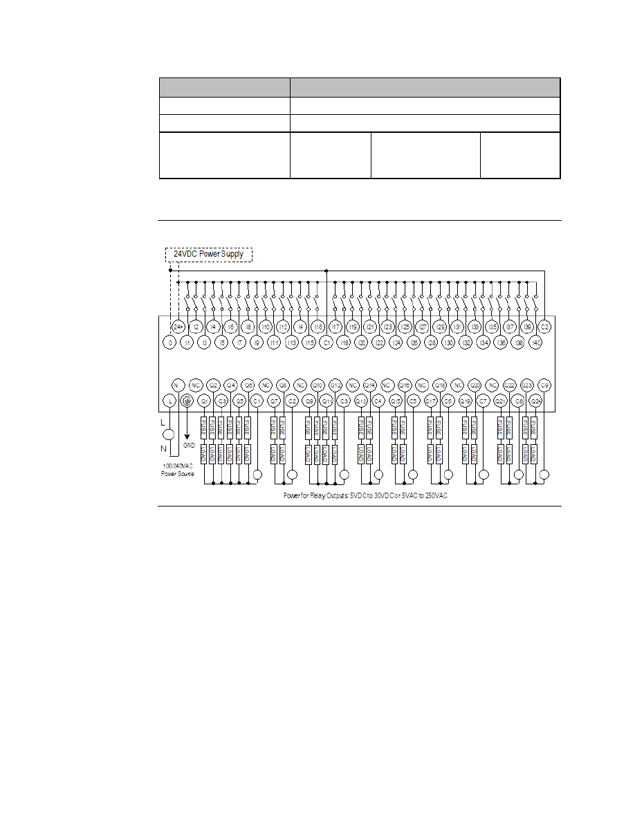
11.4.4


Wiring Diagram, IC200UEX264 

Figure 91 


User Manual 

Chapter 11 

GFK-1645M 

Dec 2019 


VersaMax Micro PLC 64-Point Expansion Units 

213 

11.5


IC200UEX364 
64 Point Micro PLC Expansion Unit, (40) 24Vdc 
In, (24) LCDC Out, 24Vdc Power Supply 

VersaMax  Micro  PLC  Expansion  Unit  IC200UEX364  accepts  forty  DC  inputs  and  provides 
twenty-four low current (LCDC) transistor outputs. It uses 24Vdc nominal input power. 

11.5.1


DC Power 

The  24Vdc  power  source  for  the  Expansion  Unit  must  have  enough  transient  current 
capability to support the inrush current of the power supply and to maintain a 24Vdc voltage 
level (see power supply specifications for inrush requirements). 

11.5.2


DC Inputs 

Forty configurable DC inputs can be used as positive or negative logic standard inputs. They 
are compatible with a wide range of input devices, such as pushbuttons, limit switches, and 
electronic proximity switches. 

The Micro PLC Expansion Unit’s +24

Vdc supply can be used for input devices and to power 

the DC input circuits at about 8mA per input. The combination of input circuit current and 
external device current must not exceed 435mA. 

11.5.3


DC Outputs 

The Micro PLC Expansion Unit IC200UEX364 has 24 sink-type DC outputs. All outputs are 
isolated between field and logic and are switching positive voltage. The outputs have one 
common incoming supply (VC) and one common ground (COM). The outputs are able to 
drive high inrush currents (8 times the rated current) and are protected against negative 
voltage pulses. This makes it possible to switch lamps and inductive loads. 


User Manual 

Chapter 11 

GFK-1645M 

Dec 2019 


VersaMax Micro PLC 64-Point Expansion Units 

214 

11.5.4


Expansion Unit IC200UEX364 Specifications 

Item


Description


Inputs 

Forty 24Vdc positive or negative logic inputs 

Outputs 

Twenty-four transistor outputs, 24Vdc. 

DC Power Specifications  

Range 

19.2Vdc to 30Vdc 

Hold-up 

10mS at 19.2Vdc 

Inrush Current 

1 Amp maximum at 30Vdc 

Inrush Time 

10mS for 1 Amp 

Input Current 

0.20 Amp typical at 24Vdc 

Input Power Supply Rating 

5W 

DC Input Specifications  

Rated Input Voltage 

24 volts DC 

Input Voltage Range 

0 to 30 volts DC  

Input Current at 24Vdc 

I1, I3, I5, I7: 8mA typical 
Other inputs: 4.8mA typical 

Input Impedance 

I1, I3, I5, I7: 2.7 kΩ


Other inputs: 4.7 kΩ


Input Threshold Voltage 

ON: 18Vdc minimum, OFF: 5Vdc maximum 

Input Threshold Current 

I1, I3, I5, I7: ON  4.5mA maximum,  OFF:  1.8mA minimum 
Other inputs: ON  3.3mA maximum, OFF: 1.6mA maximum 

Response Time (Input Lag) 

I1, I3, I5, I7: 1.5ms maximum 
Other inputs: 2ms maximum 

Isolation Voltage 

1500V RMS field side to logic side, 500V RMS between groups 

Output Specifications  

Voltage Range 

12Vdc/24Vdc 

External Power Supply 

12/24Vdc 

10%, +20% 

Maximum Load Current 

0.5A per point (Q1 

 Q24) at 24Vdc 

Minimum Switching Current  10mA 

Maximum Inrush Current 

Q1-Q24: 2A for 20ms, 1 pulse 

Output Voltage Drop 

Q1

 Q24: 

0.3Vdc 

OFF state leakage current 

0.1mA 

Response Time  
(OFF-to-ON and ON-to-OFF) 

1mS maximum @ 24Vdc 

Isolation Voltage 

1500V RMS between field side and logic side, 500V RMS between 
groups 

Fuses 

None 

Under-voltage shutdown 

Q1 

 Q24: 5V minimum, 8V maximum  

DC short circuit current 

Q1 

 Q24: 0.7A minimum, 2A maximum 


User Manual 

Chapter 11 

GFK-1645M 

Dec 2019 


VersaMax Micro PLC 64-Point Expansion Units 

215 

11.5.5


Wiring Diagram, IC200UEX364 

Figure 92 


User Manual 

Chapter 12 

GFK-1645M 

Dec 2019 


Analog Expansion Units 

216 

Chapter 12:


Analog Expansion Units 

This chapter describes the following VersaMax Micro PLC Analog Expansion Units:    

IC200UEX616  6 Point Analog Expansion Unit, (4) Analog In and (2) Analog Out, 12Vdc Power 

Supply 

IC200UEX624  4 Point Analog Expansion Unit, (4) Analog In, 24Vdc Power Supply 

IC200UEX626  6 Point Analog Expansion Unit, (4) Analog In and (2) Analog Out, 24Vdc Power 

Supply 

IC200UEX636  6  Point  Analog  Expansion  Unit,  (4)  Analog  In  and  (2)  Analog  Out,  100/240Vac 

Power Supply 

12.1


Features of Analog Expansion Units 

Analog, Expansion Units have the features shown below.  Expansion Units can be located 
up to 2 meters from the Micro PLC. 

Figure 93 


12.1.1


Removable Terminal Strips 

The removable terminal assemblies are protected by hinged covers. After turning off power 
to the Expansion Unit, a terminal assembly and attached field wiring can be separated from 
the Expansion Unit by removing two screws. 

12.1.2


Expansion Connector 

The connector on the left side of the Expansion Unit is used to connect to the Micro PLC or 
to the outgoing connector on the previous Expansion Unit. The connector on the right side 
of the Expansion Unit can be used to attach to the next Expansion Unit. 


User Manual 

Chapter 12 

GFK-1645M 

Dec 2019 


Analog Expansion Units 

217 

12.1.3


Status LEDs 

LEDs on the Expansion Unit provide quick visual verification of operating status. Expansion 
Unit LEDs indicate local Power and OK mode. 

12.1.4


Cables 

A 0.1-meter ribbon cable (IC200CBL501) is provided with each Expansion Unit. Cables are 
also available in 0.5-meter (IC200CBL505) and 1 meter (IC200CBL510) lengths. 

12.2


Analog Expansion Unit Specifications 

Module Dimensions 

Height: 90mm (3.6”), Depth: 76mm (3.0”) Width: 150mm (6.0 “) 


Inputs 

4 analog inputs  

Outputs 

2 analog outputs (all models except UEX624) 

12.2.1


Power Specifications for Analog Expansion Units  


IC200UEX616 

IC200UEX624, 
UEX626  

IC200UEX636 

Power voltage 

12Vdc 

24Vdc 

100/110/120/200/210/220V 
(50/60Hz)Vac 

Range 

9.6Vdc - 15Vdc 

19.2Vdc to 30Vdc  85 to 264Vac 

Hold-up 

10.1ms at 9.6V 

24.5ms at 19.2V 

223ms at 85V 

Inrush Current/Time 

0.9A / 1ms at 15V  2.5V / 1ms at 30V  4A / 5ms at 264V 

Input Current 

0.15A at 15V 

0.1A at 30V 

0.06A at 264V 

Input Power Supply Rating  2.25W 

3W 

15VA 

The DC power source must have enough transient current capability to support the inrush 
current of the power supply and to maintain the nominal voltage level. 

12.2.2


Input and Output Specifications 

Item


Description


Analog Input Channels (IC200UEX6**)  4, differential 

Input ranges 

0 to 10V (10.23V maximum) 
-10V to +10V (-10.23V min. and +10.23V max.) 
0 to 20mA (20.47mA maximum) 
4 to 20mA (20.47mA maximum) 

Resolution 

12 bits  

Accuracy  

±1% of full scale over full operating temperature range 

Linearity 

±3 LSB maximum 

Isolation 

non-isolated 

Common mode voltage 

±40 V maximum 

Current input impedance 

249 Ω  


User Manual 

Chapter 12 

GFK-1645M 

Dec 2019 


Analog Expansion Units 

218 

Item


Description


Voltage input impedance 

200 kΩ  


Input filter time 

20ms to reach 1% error for step input   

Analog Output Channels 

2, single-ended, non-isolated 

Output ranges 

0 to 10V (10.23V maximum) 
0 to 20mA (20.47mA maximum) 
4 to 20mA (20.47mA maximum) 

Resolution 

12 bits  

Accuracy 

±1% of full scale over operating temperature range 

Current: maximum terminal voltage 
 

user load range 


output load capacitance 


output load inductance 

10V (at 20mA output) 

10 to 500 Ω


2000 pF maximum 
1 Henry maximum 

Voltage: output loading 
 

output load capacitance 

10 kΩ minimum at 10 volts


1 µF maximum 

12.3


Analog Operation 

This  section  explains  how  a  VersaMax  Micro  PLC  Expansion  Unit  with  analog  channels 
processes analog data. Unlike discrete expansion units, if one analog unit fails all subsequent 
analog  expansion  units  will  stop  communicating.  However,  expansion  units  before  the 
failed unit continue to be available.  If an analog expansion fails at power up, no expansion 
units (discrete or analog) will be functional. 

12.3.1


Analog I/O Parameters 

Each  analog  channel  can  be  configured  to  operate  in  either  voltage  or  current  mode.  If 
current mode operation is selected, the range can then be configured as either 4-20mA or 
0-20mA.  If  voltage  mode  operation  is  selected  (inputs  only),  the  range  can  then  be 
configured as either 0-10V or 

10V to +10V. 

Parameter 

Choices 

Default Value 

Voltage or current mode 

Voltage, Current 

Voltage 

Current range selection 

4

20mA, 0

20mA 

4

20mA 

Voltage range selection (Inputs Only)  0-10V, -10-+10V 

0-10V 


User Manual 

Chapter 12 

GFK-1645M 

Dec 2019 


Analog Expansion Units 

219 

12.3.2


Input/Output Values Compared to Process Data 

The  Expansion  Unit  processes  analog  channels  using  fixed  conversion  values  for  both 
current and voltage mode operation. The table below shows the relationship between the 
analog  input  and  output  values  used  by  the  application  program,  and  the  actual  analog 
input or output for each mode. These values include the automatic adjustments for gain. 

In this 
Configured 
Mode: 

This is the 
Analog Signal 
Range 

This is the Equivalent 
Process Data %AI or 
%AQ Range 

For the Default 
Calibration, the Value in 
the  
%AI or %AQ Reference 
Equals: 

Voltage 0 to +10V  0 to 10,000mV 

0 to 32000 

3.2 x mV 

Voltage 

10 to 

+10V (Inputs Only) 

-10,000mv to 
+10,0000mV 

-32000 to 32000 

3.2 x mV 

Current 0 to 20mA  0 to 20,000µA 

0 to 32000 

1.6 x µA 

Current 4 to 20mA  4,000 to 20,000µA  0 to 32000 

2 x µA 

8000 

12.3.3


Count Resolution for Analog Expansion Units 

For analog expansion units, count resolution is controlled by a DIP switch 6, which is set to 
ON by default. If unexpected results are observed, check the position of switch 6. If switch 6 
is not ON, power down the system and set switch 6 to ON, as shown in the following figure. 
Do NOT change any of the other switches. 

Figure 94 


12.3.4


LED Indications 

The module’s LEDs indicate the status of the module and of the analog inputs.


IN1  IN2  IN3  IN4 

POW   


OK 


If an initialization error occurs, the OK LED blinks rapidly. During normal operation, the 
analog input LEDs should be off.


User Manual 

Chapter 12 

GFK-1645M 

Dec 2019 


Analog Expansion Units 

220 

12.3.5


Analog Input Processing 

The Expansion Unit processes analog input channels with a 12-bit successive-approximation 
A/D converter. It converts the analog value into a digital count, calculates the %AI value as 
described  below,  then  places  the  result  into  the  appropriate  %AI  input  reference  (these 
references are described in Chapter 22:)

Figure 95 


Automatic Conversion of Analog Voltage or Current to 
Counts 

In voltage mode, the Expansion Unit first converts the 0 to 10,000mV input signal to a count 
in the range of 0 to 4,000 (or 

10,000mV to 10,000mV signal to a range of 

4,000 to 4,000). 

The fixed multiplier for this conversion is 2.5.  

In current mode, the Expansion Unit first converts the 0 to 20,000µA input signal to a count 
value in the range of 0 to 4,000. The fixed multiplier for this conversion is 5. The conversion 
for both current modes (0-20mA and 4-20mA) is the same. 

Automatic Gain and Offset Adjustment for Analog Inputs 

The Expansion Unit then converts the A/D converter's input count value from the range of 0 
to 4000 to a final %AI input value in the range of 0 to 32,000. It multiplies the count value by 
8 (32000 / 4000) to get the final analog input ($AI): 

(input count X 8) = %AI value 

Any calculated value above 32,767 is clamped at that maximum value. Any calculated value 
less than 0 is clamped at 0.  

Analog Input Conversion Summary 

The table below summarizes the conversion of voltage or current inputs to counts and then 
to %AI values. 

Input Signal 

Conversion 
Factor 

A/D Converter 
Value 

Gain 
Factor 

%AI Range 

Voltage Mode  
(0 to 10,000mV) 

2.5 

0

4000 counts 

0

32,000 

Voltage Mode  
(-10,000 to 10,000mV) 

2.5 

-4000 to 4000 counts  8 

-32,000 to 32,000 

Current Mode 
(0

20mA) or (4

20mA) 

0

4000 counts 

0

32,000 


User Manual 

Chapter 12 

GFK-1645M 

Dec 2019 


Analog Expansion Units 

221 

12.3.6


Analog Output Processing 

To generate the analog output signal, the  Expansion Unit converts the value in the %AQ 
output  reference  into  a  count  value  for  the  12-bit  D/A  converter,  which  then  drives  the 
analog output. 

Figure 96 


Automatic Gain and Offset Adjustment for Analog Outputs 

The  application's  %AQ  output  range  of  0  to  32000  corresponds  to  the  D/A  converter's 
output count range of 0 to 4000. The Expansion Unit first multiplies the %AQ value from the 
program by .125 (4000 / 32000) to produce the count value for the D/A converter: 

(%AQ X .125) = D/A count 

Any calculated value that exceeds  4095 (212-1) is clamped at that  maximum value. Any 
calculated value less than 0 is clamped at 0.  The range 0 to 4095 corresponds to %AQ values 
between 0 and 32,767. 

Automatic Conversion of Counts to Analog Voltage or 
Current 

In voltage mode, the D/A converter then converts the count value in the range of 0 to 4,000 
counts  to  an  analog  signal  from  0  to  10,000mV.  The  output  voltage  gain  (ratio)  for  this 
conversion is 2.5. 

In current mode, the D/A converter converts the count value to an analog signal from 0 to 
20,000µA. The output current gain for this conversion is 5. The conversion for both current 
modes (0-20mA and 4-20mA) is the same. 

Analog Output Data Conversion Summary 

The table below summarizes the conversion of %AQ values to counts and then to voltage or 
current levels. 

%AQ 
Range 

Gain 
Factor 

D/A Converter 
Range 

Conversion 
Factor 

Output Signal 

0

 32,000 

0.125 

0

4,000 counts 

2.5 

Voltage Mode (0

10,000mV) 

0

32,000 

0.125 

0

4,000 counts 

Current Mode 

(0

20mA)  


or (4

20mA) 


User Manual 

Chapter 12 

GFK-1645M 

Dec 2019 


Analog Expansion Units 

222 

12.3.7


Wiring Diagram 

Figure 97 


On modules IC200UEX616, UEX626 and UEX 636, voltage and current outputs are present 
on their respective output terminals at the same time. For proper module operation, only 
the output terminals that correspond to the voltage / current output configuration should 
be connected. 


User Manual 

Chapter 13 

GFK-1645M 

Dec 2019 


RTD and Thermocouple Expansion Units 

223 

Chapter 13:


RTD and Thermocouple 
Expansion Units 

This chapter describes the following VersaMax Micro PLC RTD and Thermocouple 
Expansion Units:  

IC200UEX724 

4 RTD, Pt 100 In, 
24Vdc Power Supply 

IC200UEX726 

4 RTD, Pt 100 In and 2 Analog Out, 

 20mA, 4 

 20mA or 0 

 10Vdc, 

24Vdc Power Supply 

IC200UEX734 

4 RTD, Pt 100 In, 
100/240Vac Power Supply 

IC200UEX736 

4 RTD, Pt 100 In and 2 Analog Out, 

 20mA, 4 

 20mA or 0 

 10Vdc, 

100/240Vac Power Supply 

IC200UEX824 

4 Thermocouple Inputs, 
24Vdc Power Supply 

IC200UEX826 

4Thermocouple Inputs and 2 Analog Out, 

 20mA or 0 

 10Vdc, 

24Vdc Power Supply 

13.1


Description of RTD and Thermocouple 
Modules 

RTD and Thermocouple Expansion Units have the features shown below.  Expansion Units 
can be located up to 2 meters from the Micro PLC. 

Figure 98 


User Manual 

Chapter 13 

GFK-1645M 

Dec 2019 


RTD and Thermocouple Expansion Units 

224 

13.1.1


Removable Terminal Strips 

The removable terminal assemblies are protected by hinged covers. After turning off 
power to the Expansion Unit, a terminal assembly and attached field wiring can be 
separated from the Expansion Unit by removing two screws. 

13.1.2


Expansion Connector 

The connector on the left side of the Expansion Unit is used to connect to the Micro PLC or 
to the outgoing connector on the previous Expansion Unit. The connector on the right side 
of the Expansion Unit can be used to attach to the next Expansion Unit.  

13.1.3


Status LEDs  

LEDs on the Expansion Unit provide quick visual verification of operating status. Expansion 
Unit LEDs indicate local Power and OK mode.  

The input channel LEDs should be OFF during proper operation.  

13.1.4


Cables 

A 0.1-meter ribbon cable (IC200CBL501) is provided with each Expansion Unit. Cables are 
also available in 0.5-meter (IC200CBL505) and 1 meter (IC200CBL510) lengths. 

13.2


RTD Expansion Modules 

VersaMax Micro PLC RTD Expansion Units are used for applications that require 
temperature monitoring and control. Four types are available: 

IC200UEX724 

4 RTD, Pt 100 In, 
24Vdc Power Supply 

IC200UEX726 

4 RTD, Pt 100 In and 
2 Analog Out, 0 

 20mA, 4 

 20mA, or 0 

 10Vdc, 

24Vdc Power Supply 

IC200UEX734 

4 RTD, Pt 100 In, 
100/240Vac Power Supply 

IC200UEX736 

4 RTD, Pt 100 In and 
2 Analog Out, 0 

 20mA, 4 

 20mA, or 0 

 10Vdc, 100/240Vac Power 

Typical applications include oven control, motor monitoring, refrigerant control, and 
environmental control. One VersaMax Micro PLC can monitor up to sixteen RTDs (four 
RTDs per expansion module, four expansion modules per Micro PLC).  

Note:   


RTD Expansion Modules support DOIO for inputs and outputs. 


If an RTD Expansion module is auto configured with DIP switch 3 OFF (Compatibility Mode), it 
reports its identity as a standard analog expansion module (IC200UEX616/626/636). This has 
no effect on module operation. 


For Micro release 4.0 and later, if the RTD Expansion module is auto-configured with DIP switch 
3 ON (High-Accuracy Mode), it reports as IC200UEX726/736. 


User Manual 

Chapter 13 

GFK-1645M 

Dec 2019 


RTD and Thermocouple Expansion Units 

225 

13.2.1


Compatibility 

RTD Expansion Units are compatible with Micro PLCs having a firmware version of 2.01 or 
greater. 

They are compatible with Logic Developer 2.60 or above and with VersaPro software 2.03 
and above. Some compatible software versions do not list these modules  separately but 
allow them to be configured as analog expansion units. Current software versions list these 
modules by number and description. 

13.2.2


RTD Module General Specifications 

Module Dimensions 

Height: 90mm (3.6 inches)   
Depth: 76mm (3.0 inches) 
Width: 150mm (6.0 inches)  

Inputs 

4 RTD inputs  

Outputs 

2 analog outputs (all models except UEX724 and UEX734) 

Power Supply Type 

DC Power Supply

5


AC Power Supply 

Power voltage 

24Vdc 

100/110/120/200/210/220Vac (50/60Hz) 

Range 

19.2Vdc to 30Vdc 

85 to 264Vac 

Allowable momentary power 
failure 

10ms 

85 to 100V: 10ms 
100 to 264V: 20ms 

Operating ambient temperature  0 to 55 C (Storage ambient temperature 

10 to 75 C) 

Operating ambient humidity 

5 to 95 % RH (no condensation) 
(Storage ambient humidity 5 to 95 % RH (no condensation)) 

Vibration resistance 

Complies with JIS C  0911 

Noise resistance 

Noise voltage 1500 Vpp; Noise pulse width 100 ns, 1 micro sec  
Static noise: 3000 V at metal exposed area 

Insulation resistance 

20 M

 or more between the AC external terminal and case 

ground (PE) terminal  
(based on 500 VDC mega) 

Dielectric withstand voltage 

500V DC 

1500Vac 

Grounding 

Class D (100

) independent grounding 

Usage environment 

No corrosive gases, no excessive dirt 

Structure 

Attaches to an open wall 

Cooling 

Natural air cooling 

Protection against electrical 
shock hazard 

Class 1 equipment 

Open equipment 


5

 The DC power source must have enough transient current capability to support the inrush current of the power supply and to maintain 

the nominal voltage level. 


Content      ..     14      15      16      17     ..