EMERSON PACSystems VersaMax MICRO PLC & NANO PLC. USER MANUAL (2019) - page 17
 

  Index      Manuals     EMERSON PACSystems VersaMax MICRO PLC & NANO PLC. USER MANUAL (2019)


Search            copyright infringement  


Content      ..     15      16      17      18     ..


EMERSON PACSystems VersaMax MICRO PLC & NANO PLC. USER MANUAL (2019) - page 17


User Manual 

Chapter 13 

GFK-1645M 

Dec 2019 


RTD and Thermocouple Expansion Units 

226 

13.2.3


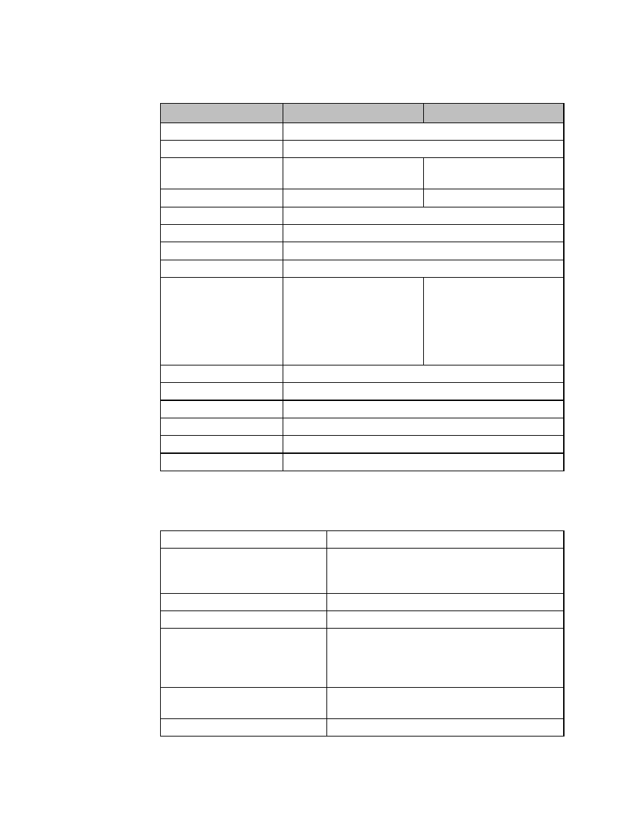
RTD Module Input Specifications 


Compatible 

High Accuracy 

RTD Input Channels 

4, differential 

Input Sensor Types 

2- and 3-wire types, PT 100 

Input ranges 

-100.0 to +600.0°C  
-150.0 to +1050.0°F 

-100.0 to +600.0°C  
-148 to +1112.0°F 

Input Resolution 

0.2°C / 0.3°F  

0.1°C / 0.1°F 

Accuracy  

±0.5% of full scale over operating temperature range 

Data Format 

0 to 32000 for °F, or 0 to 28000 for °C 

Constant Current 

Approximately 1mA 

Channel Update Time 

141/563ms (selectable) for all channels 

Diagnostics 

LED on module blinks when input 
values at 

100°C (-150°F) or less, 

or 600°C (+1050°F) or more 
(includes cable disconnection) 
Also, the channel input data will 
contain 7FF8H 

LED on module blinks when input 
values at 

110°C (-166°F) or less, 

or 610°C (+1130°F) or more 
(includes cable disconnection) 
Also, the channel input data will 
contain 7FFFH 

Digital Resolution 

15 bits + sign 

Open Circuit Detection Time  141ms or 563ms, excluding logic execution 

Channel to Channel Isolation  None 

Maximum Lead Resistance 

100Ω


Converter Type 

Successive approximation 

Excitation 

Current Source 1.0mA 

13.2.4


RTD Module Output Specifications 

Only modules IC200UEX 726 and UEX736 have outputs. 

Analog Output Channels 

2, single-ended, non-isolated 

Output ranges 

0 to 10V (10.23V maximum) 
0 to 20mA (20.47mA maximum) 
4 to 20mA (20.47mA maximum) 

Resolution 

12 bits  

Accuracy 

±1% of full scale over operating temperature range 

Current:  maximum terminal voltage 
 

user load range 


output load capacitance 


output load inductance 

10V (at 20mA output) 

10 to 500 Ω


2000 pF maximum 
1 Henry maximum 

Voltage:  output loading 
 

output load capacitance 

10 kΩ minimu

m at 10 volts 

1 µF maximum 

Response Time 

8.8ms 


User Manual 

Chapter 13 

GFK-1645M 

Dec 2019 


RTD and Thermocouple Expansion Units 

227 

13.2.5


Scaling 

Scaling for RTD Inputs 

An RTD Expansion Unit (in the Compatible mode) processes input channels with a 12-bit 
successive-approximation A/D converter. It converts the input value into a digital  count, 
calculates the %AI value as described below, then places the result into the appropriate %AI 
input reference (these references are described in Chapter 22:)

Figure 99 


The table below lists equivalent decimal and hexadecimal conversion values for Celsius and 
Fahrenheit inputs. 

Input Signal 

A/D Converter Value 

Gain Factor 

%AI Range 

Celsius Mode (-100°C to 600°C)  0 

 3500 counts 

0 - 28000 

Fahrenheit  Mode  (-150   F  to 
1050°F) 

 4000 counts 

0 - 32000 

Scaling for Analog Outputs 

To generate the analog output signal, the RTD Expansion Unit converts the value in the %AQ 
output  reference  into  a  count  value  for  the  12-bit  D/A  converter,  which  then  drives  the 
analog output. 

Figure 100 


Automatic Gain and Offset Adjustment for Analog Outputs 

If  DIP  switch  6  is  in  the  ON  position  (default)  the  D/A  Converter’s  output  range  is  4,000 

counts. If this DIP switch is set to the OFF position, the output range is 4,096 counts. 

The  application's  %AQ  output  range  of  0  to  32000  corresponds  to  the  D/A  converter's 
output count range. The Expansion Unit first multiplies the %AQ value from the program by 
(output range / 32000) to produce the count value for the D/A Converter: 

Compatible resolution mode: (%AQ ×

32000

4000

) = (%AQ × 0.125) = D/A count 

Maximum resolution mode: (%AQ ×

32000

4096

) = (%AQ ×X 0.128) = D/A count 

User Manual 

Chapter 13 

GFK-1645M 

Dec 2019 


RTD and Thermocouple Expansion Units 

228 

Any  calculated  value  that  exceeds  4095  (2

12

-1)  is  clamped  at  that  maximum  value.  Any 

calculated value less than 0 is clamped at 0.  The range 0 to 4095 corresponds to %AQ values 
between 0 and 32,760. 

Automatic Conversion of Counts to Analog Voltage or Current 

In  voltage  mode,  the  D/A  Converter  converts  the  count  value  in  the  range  of 
0

4,000 or 0

4,096 counts to an analog signal from 0 to 10,000mV. The output voltage 

gain (ratio) for this conversion is 2.5.  

In compatible resolution mode (D/A Converter range is 0

4,000), loading a count value of 

32760 results in an analog output value of 10.23V. 

In maximum resolution mode (D/A Converter range is 0

4,096), loading a count value of 

32760 results in an analog output value of 10.00V 

In current mode, the D/A converter converts the count value to an analog signal from 0 to 
20,000µA. The output current gain for this conversion is 5. The conversion for both current 
modes (0-20mA and 4-20mA) is the same. 

Range 

0000 

2000 H07D0 

4000 H0FA0 

4095 H0FFF 

0-10V 

0V 

5V 

10V 

10.23V 

0-20mA 

0mA 

10mA 

20mA 

20.47mA 

4-20mA 

4mA 

12mA 

20mA 

20.38mA 

13.2.6


Wiring for RTD Expansion Modules 

Figure 101 


On modules IC200UEX726 and UEX736, voltage and current outputs are present on their 
respective output terminals at the same time. For proper module operation, only the 
output terminals that correspond to the voltage / current output configuration should be 
connected. 

User Manual 

Chapter 13 

GFK-1645M 

Dec 2019 


RTD and Thermocouple Expansion Units 

229 

13.3


Module Installation 

1.


To avoid risk of electric shock, turn off power to the Micro PLC and disconnect the 
main power before connecting the RTD expansion modules. 

2.


Loosen  the  screws  on  the  terminal  block  and  attach  unit  power,  RTD  wires  and 
analog outputs. Tighten all screws securely. The RTD wires should be the same type 
and length (except for the jumper used in a two-wire RTD) to ensure accuracy. Do 
not use the shield or drain wire for the third connection. 

3.


If all RTD 

channels are not used, a 100 to 300 Ω resistor can be connected across 

terminal A to B with a jumper connected from B to b. The resistor will disable the 
diagnostics and stop the channel LED from flashing.  

4.


Connect the expansion cable to the Micro PLC or expansion unit to the left of the 
RTD Expansion Unit. 

5.


Turn power on. Check the LEDs as shown on the next page. The Power and OK LEDs 
should be ON. The LEDs for channels 1 to 4 should be OFF during normal operation 
if the RTDs are connected properly. 

13.3.1


DIP Switches 

The default DIP switch settings for the RTD units are switches 1-5 and 7-8 OFF and switch 6 
ON. 

For RTD expansion units, DIP switch 2 selects the RTD channels update rate. In the factory 
default OFF position, switch 2 selects a 562ms update rate. The update rate can be changed 
to 141ms by moving switch 2 to the ON position.  

From  Release  4.0  and  above,  DIP  Switch  3  can  be  used  to  select  between  Compatible 
(Switch 3 OFF) and High Accuracy (Switch 3 ON) modes. In the PME configuration of RTD 

module,  selection  for  “Conversion  mode”  parameter  should  match  this  DIP  switch 

selection. 

Default DIP Switch Settings for RTD Expansion Module 

Figure 102 


User Manual 

Chapter 13 

GFK-1645M 

Dec 2019 


RTD and Thermocouple Expansion Units 

230 

Note:   


Do NOT change the settings of any of the other DIP switches. 


The module must be powered OFF before changing the DIP switch settings. 


13.3.2


LED Indications 

The module’s LEDs indicate the status of the module and of the RTD inputs.


RTD1 

RTD2 

RTD3 

RTD4 

POW 


OK 


If an initialization error occurs, the OK LED blinks rapidly. 

During normal operation, the RTD input LEDs should be off. If an RTD input is outside the 
range of -100°C (-150°F) to +600°C (1050°F), its LED blinks. 

13.3.3


Data Conversion for RTD Expansion Units (in Compatible 
mode) 

Individual  channels  on  an  RTD  Expansion  Units  can  be  individually  configured  for  either 
Celsius or Fahrenheit  

If Celsius is configured, the range of data for a channel is 0 to 28,000.  

If Fahrenheit is configured, the range of data for the channel is 0 to 32,000. 


Values below 0 indicate shorted cable. 


Values above 28,000 (when configured for Celsius) or 32,000 (when configured for 
Fahrenheit) indicate disconnected (open) or shorted cable. 


User Manual 

Chapter 13 

GFK-1645M 

Dec 2019 


RTD and Thermocouple Expansion Units 

231 

Basic Temperature Conversion Logic 

Figure 103 


The Scaling function (see Chapter 23:) can be use in the application program to convert the 
raw counts value for a channel to a temperature measurement in degrees. The ranges are 
100 to +600 degrees C and  150 to +1050 degrees F. The example logic shown here applies 
to Compatible mode only. 


User Manual 

Chapter 13 

GFK-1645M 

Dec 2019 


RTD and Thermocouple Expansion Units 

232 

High-Resolution Temperature Conversion Logic for RTD 
Units 

For accuracy in tenths of degrees, the Data Type Conversion functions (see Chapter 23:) 
can be added to the program logic. See the examples (for the Compatible mode) below. 

Figure 104 


Celsius Conversion 

Line 15: Converts RTD to Real Value.  Data will be stored in two consecutive Registers 100 
and 101 

Line 16: Divides the raw value by 40.0 (28000/700) 700 comes from the full temperature 
range of 600 to 

100 C.  Result is placed in R102 and R103 

Line 17: Subtracts 100 for conversion.  This is to offset the 

100 and the result is in R104 and 

R105 


User Manual 

Chapter 13 

GFK-1645M 

Dec 2019 


RTD and Thermocouple Expansion Units 

233 

Fahrenheit Conversion 

Line 18: Converts RTD to Real Value.  Data will be stored in two consecutive Registers 110 
and 111 

Line  19:  Divides  the  raw  value  by  26.66667  (32,000/1200)  1200  comes  from  the  full 
temperature range of 1050 to 

150 F.  Result is placed in R112 and R113 

Line 20: Subtracts 150 for conversion.  This is to offset the 

150 and the result is in R114 and 

R115 

13.4


Thermocouple Expansion Modules 

VersaMax Micro PLC Thermocouple Expansion modules are used for applications such as 
food and beverage production, process control, and environmental control. The following 
types of Thermocouple expansion module are available: 


IC200UEX824    4 Thermocouple Inputs, 24Vdc Power Supply 


IC200UEX826    4 Thermocouple Inputs and 2 Analog Outputs, 24Vdc Power Supply 

One VersaMax Micro PLC can monitor up to sixteen thermocouples (four thermocouples per 
expansion module, four expansion modules per Micro PLC).  

Note:   


Thermocouple Expansion modules support DOIO for inputs and outputs. 


If  a Thermocouple  Expansion  module  is  auto  configured  with  DIP  switch  6  OFF  (Compatibility 
Mode), it reports its identity as a standard analog expansion module (IC200UEX616/626/636). 
This has no effect on module operation. 


For Micro release 4.0 and later, if the Thermocouple Expansion module is auto-configured with 
DIP switch 6 ON (High-Accuracy Mode), it reports as IC200UEX826. 


13.4.1


Compatibility 

Thermocouple Expansion modules are compatible with: 


VersaMax Micro-20, -40, and -60 CPUs version 3.81 or later.  


VersaMax Micro-23 and 

28 CPUs version 3.55 or later.  


VersaMax Micro-14 CPUs version 3.56 or later. 

They are configurable using Logic Developer 5.70 and above. Some compatible software 
versions  do  not  list  these  modules  separately  but  allow  them  to  be  configured  as  RTD 
expansion units, as described later in this section. 


User Manual 

Chapter 13 

GFK-1645M 

Dec 2019 


RTD and Thermocouple Expansion Units 

234 

13.4.2


Thermocouple Module General Specifications 

Module Dimensions 

Height: 90mm (3.6 inches)   
Depth: 76mm (3.0 inches) 
Width: 150mm (6.0 inches)  

Inputs 

4 Thermocouple inputs  

Outputs 

Model IC200UEX826 only: 2 analog outputs  

Power voltage 

24Vdc 

Range 

19.2Vdc to 30Vdc 

Inrush Current/Time 

2.5A / 1ms at 30V 

Input Current 

0.1A at 30V 

Input Power Supply Rating 

3W 

Allowable momentary power failure 

10ms 

Operating ambient temperature 

0°C to 55°C (Storage ambient temperature 

10°C to 75°C) 

Operating ambient humidity 

5 to 95 % RH (no condensation) 
(Storage ambient humidity 5 to 95 % RH (no condensation)) 

Vibration resistance 

Complies with JIS C 0911 

Noise resistance 

Noise voltage 1500 Vpp Noise pulse width 100 ns, 1 µs  
Static noise: 3000 V at metal exposed area 

Insulation resistance 

20 M

 or more between the AC external terminal and case 

ground (PE) terminal  

Dielectric withstand voltage 

500V DC 

Grounding 

Class D (100

) independent grounding 

Usage environment 

No corrosive gases, no excessive dirt 

Structure 

Attaches to an open panel 

Cooling 

Natural air cooling 

Protection against electrical shock 
hazard 

Class 1 equipment 

Open equipment 

13.4.3


Analog Output Specifications (Model IC200UEX826) 

Analog Output Channels 

2, single 

Output Ranges 

0-10 V (10.24 V maximum), 0-20 mA (20.48 mA maximum) 

Resolution 

0-10 V, 12 bits, 0-20 mA, 12 bits 

Accuracy 

±1% of full scale over temperature range 

Current Outputs 

Max. Voltage at    

20 mA: 10 V 

User Load Range:  10 to 500


Output Load Capacitance: 2000 pF Maximum 
Output Load Inductance:  1 Henry Maximum 

Voltage Outputs 

Output Loading:   

10 k

 Minimum at 10 V 

Output Load Inductance:  1 µF Maximum 

Response time 

8.8 ms 


User Manual 

Chapter 13 

GFK-1645M 

Dec 2019 


RTD and Thermocouple Expansion Units 

235 

13.4.4


Thermocouple Module Input Specifications 

Input Channels 

4, differential 

Sensor type 

Following JIS C 1602-1995 
Type K, J, E, S, T, B, N, -/+50mV, -/+100mV 

Temperature 
range and 
accuracy  
(±%) at 0 to 
55°C 

Type 

Accuracy range 

6


Input range 

7


-200 to 1200°C (-328 to 2192F) 
0.4%(FS) 

-270 to 1370°C (-454 to 
2498°F) 

-40 to 750°C ( -40 to 1382°F) 
0.3%(FS) 

-210 to 1200°C (-316 to 
2192°F) 

-200 to 900°C (-328 to 1652°F) 
0.3%(FS) 

-270 to 1000°C (-454 to 
1832°F) 

0 to 1600°C ( 32 to 2912°F) 1.0%(FS) 

-50 to 1760°C (-58 to 
3200°F) 

-200 to 350C (-328 to 662F) 
0.8%(FS) 

-270 to 400°C (-454 to 
752°F) 

600 to 1700°C (1112 to 3092°F) 
1.0%(FS) 

0 to 1820°C (32 to 3308°F) 

-200 to 1200°C (-328 to 2192°F) 
0.4%(FS) 

-270 to 1300°C (-454 to 
2372°F) 

±50mV 

-50 to 50mV 0.5%(FS) 

-50 to 50mV 

±100mV  -100 to 100mV 0.5%(FS) 

-100 to 100mV 

TC mode 

High Accuracy Mode 

Compatible Mode 

Resolution 

K,J,E,T,N  0.1°C/0.2°F 

0.5C/1°F 

B,S 

1.0°C/1.0°F 

1.0°C/1°F 

±50mV 

0.01mV 

0.025mV 

±100mV  0.02mV 

0.05mV 

Units of data output 

0.1°C/0.1°F 
0.01mV 

0.5°C/1°F 
0.025mV, 0.05mV 

Conversion data 

15 bits + sign 

Cold junction 
compensation accuracy 

Less than ±2°C  (ambient temperature is 0 to 55°C) 

Cold junction input range 

-20°C to 80°C 

Diagnostics (Broken 
Wire/Under or Over range 
reporting) 

LED indication (per channel) 
Channel input data is 7FFF 
hexadecimal 

LED indication (per channel) 
Channel input data is 7FF8 
hexadecimal 

Conversi
on time 

K, J, E, T, N, 
B, S 

563ms (4ch. total) 

±50, 100mV 

141ms (4ch. total) 


6

 Accuracy Range represents measurements within which operation of the module is guaranteed. 

7

 The Input Range represents an extended range for which operation cannot always be guaranteed. 

User Manual 

Chapter 13 

GFK-1645M 

Dec 2019 


RTD and Thermocouple Expansion Units 

236 

13.4.5


Scaling for Thermocouple Module Data 

Scaling for Inputs 

A Thermocouple Expansion Unit (in the Compatibility mode) processes input channels with 
a 12-bit successive-approximation A/D converter. It converts the input value into a digital 
count,  calculates  the  %AI  value  as  described  below,  then  places  the  result  into  the 
appropriate %AI input reference (these references are described in Chapter 22:). 

Figure 105 


The table below lists equivalent decimal and hexadecimal conversion values for Celsius and 
Fahrenheit inputs. 

Input Signal 

A/D Converter Counts Value 

Gain Factor  %AI Range 

Celsius  mode  (-249.5°C  to 
1760°C) 

 4020 counts 

8 - 32160 

Fahrenheit mode (-499°F to 
3308°F) 

 3808 counts 

8 - 30464 

Voltage mode (±50mV) 

48 

 4048 counts 

384 

 32384 

Voltage mode (±100mV) 

48 

 4048 counts 

384 - 32384 

13.4.6


Scaling for Analog Outputs (Model IC200UEX826) 

To generate the analog output signal, the Thermocouple Expansion Unit converts the value 
in the %AQ output reference into a count value for the 12-bit D/A converter, which then 
drives the analog output. 

Figure 106 


Automatic Gain and Offset Adjustment for Analog Outputs 

The  application's  %AQ  output  range  of  0  to  32000  corresponds  to  the  D/A  converter's 
output count range of 0 to 4000. The Expansion Unit first multiplies the %AQ value from the 
program by 0.125 (=4000/32000) to produce the count value for the D/A converter: 

(%AQ X 0.125) = D/A count 

User Manual 

Chapter 13 

GFK-1645M 

Dec 2019 


RTD and Thermocouple Expansion Units 

237 

Any calculated value that exceeds  4095 (212-1) is clamped at that  maximum value. Any 
calculated value less than 0 is clamped at 0.  The range 0 to 4095 corresponds to %AQ values 
between 0 and 32,760. 

Automatic Conversion of Counts to Analog Voltage or Current 

In voltage mode, the D/A converter then converts the count value in the range of 0 to 4,000 
counts  to  an  analog  signal  from  0  to  10,000mV.  The  output  voltage  gain  (ratio)  for  this 
conversion is 2.5.  

In current mode, the D/A converter converts the count value to an analog signal from 0 to 
20,000µA. The output current gain for this conversion is 5.  

Range 

0000 

2000 
H07D0 

4000 
H0FA0 

4095 
H0FFF 

0-10V 

0V 

5V 

10V 

10.24V 

0-20mA 

0mA 

10mA 

20mA 

20.48mA 

13.4.7


Thermocouple Module Configuration 

Micro  PLC  firmware  versions  4.0  and  above  provide  complete  support  to  Thermocouple 
modules  including  the  High-Accuracy  mode.  Also  PME  versions  6.0  SIM1  and  above 
completely  support  the  Thermocouple  modules  (i.e.  no  workaround  with  RTD  modules 
needed for thermocouple configuration). Each channel of a Thermocouple Expansion Unit 
can be individually configured for Sensor selection, Mode (Celsius or Fahrenheit) and Cold 
Junction Compensation (Enable or Disable) 

The following description of this section is applicable only for CPU and PME versions prior to 
that of the above mentioned.  

With  Logic  Developer  (PME)  5.70  and  above,  Thermocouple  module  can  easily  be 
configured by selecting the corresponding RTD module in the Module window.  

Thermocouple Module 

Corresponding RTD Module 

IC200UEX824 

IC200UEX724 

IC200UEX826 

IC200UEX726 

The  Input  Channel  Mode  for  each  of  the  Thermocouple  channels  can  be  configured  as 
Celsius or Fahrenheit.  

For  IC200UEX826,  the  Output  Channel  Mode  parameter  can  be  used  to  configure  the 
Voltage/Current values of a Thermocouple module. 


If the selection is Voltage, the Output Channel Range is not available. 


If the selection is Current, the Output Channel Range MUST be 0 to 20 mA.   


User Manual 

Chapter 13 

GFK-1645M 

Dec 2019 


RTD and Thermocouple Expansion Units 

238 

Figure 107 


Also,  for  versions  earlier  than  4.0,  the  Cold  Junction  Compensation  is  always  enabled  by 
default and cannot be disabled either through PME or through DIP switch settings. 

13.4.8


Wiring for Thermocouple Expansion Modules 

Figure 108 


On  module  IC200UEX826,  voltage  and  current  outputs  are  present  on  their  respective 
output terminals at the same time. For proper module operation, only the output terminals 
that correspond to the voltage / current output configuration should be connected. 

User Manual 

Chapter 13 

GFK-1645M 

Dec 2019 


RTD and Thermocouple Expansion Units 

239 

13.5


Module Installation 

1.


To avoid risk of electric shock, turn off power to the Micro PLC and disconnect the 
main power before connecting Thermocouple expansion modules.  

2.


Connect the expansion cable to the Micro PLC or expansion unit to the left of the 
Thermocouple Expansion Unit. 

3.


Check the DIP switch settings as shown on the next page.  

4.


Turn power on. Check the LEDs as shown on the next page. The Power and OK LEDs 
should be ON. The LEDs for channels 1 to 4 should be OFF during normal operation 
if the thermocouple inputs are connected properly. 

5.


Connect  the  Cold  Junction  sensor.  If  that  is  not  done,  all  four  module  LEDs  flash 
continuously. 

13.5.1


DIP Switch Settings 

Micro  PLC  firmware  versions  4.0  and  above  provide  complete  support  to  Thermocouple 
modules including the High-Accuracy mode. DIP Switch 6 can be used to select between 
Compatible  (Switch6  OFF)  and  High  Accuracy  (Switch  6  ON)  modes.  In  the  PME 
configuration 

of  Thermocouple  module,  selection  for  “Conversion  mode”  parameter 

should match  this  DIP switch selection. As PME versions 6.0  SIM1  and  above completely 
support  the  Thermocouple  modules,  (when  the  Micro  PLC  firmware  version  is  4.0  and 
above) Sensor/ mV selection should be done using PME instead of through DIP Switches as 
PME  settings  always  override  the  DIP  switch  settings.  Hence  the  following  description 
applies only to the CPU and PME versions prior to that of the above mentioned.  

The sensor selection for all input channels can be configured ONLY using DIP switches 1 to 
3, it cannot be done using Logic Developer. If DIP switches 1-3 are set for mV selection (all 
On), the settings take precedence over the Logic Developer configuration of Input Channel 
Mode  and  Range.  The  module  must  be  powered  OFF  before  changing  the  DIP  switch 
settings. 

Switch 

Default 

Function 

mV 

off 

Input Sensor 
selection (Ch1-4) 

off  on 

off 

on  off 

on 

off 

on 

off 

off  off 

on 

on  off 

off 

on 

on 

off 

off  off 

off 

off  on 

on 

on 

on 

off 

mV selection 
(Valid when DIP 
Switches 1,2,3 
are all On.) 

Off => 50mV 

On => 100mV 

Do NOT change settings of any of the other DIP switches. The default setting for all other 
DIP switches is Off. 

For Thermocouple units, setting switch 6 to On causes a System Configuration Mismatch 
fault in the PLC Fault Table. For these modules, auto-configuration with specified switch On 
will  flash  error  code  12-

2  on  the  CPU’s  OK  LED.  If  this  error  occurs,  the  CPU  OK  LED  will 

repeatedly follow the sequence: 

User Manual 

Chapter 13 

GFK-1645M 

Dec 2019 


RTD and Thermocouple Expansion Units 

240 


Blink 12 times 


Go Off (short) 


Blink 2 times 


Go Off (long pause) 

To restore normal functionality, turn off power to the PLC and expansion units and set the 
DIP switch to Off. Turn On power to the PLC and expansion units again. 

13.5.2


LED Indications 

The 

module’s LEDs indicate the status of the module and the inputs.


TC1  TC2  TC3  TC4 

POW   


OK 


1.


If an initialization error occurs, the OK LED blinks rapidly. 

2.


If an input signal is out of range or the cable is disconnected, its corresponding LED 
blinks every 1 second with almost equal On and Off time. In addition, in this case the 
channel input data contains the value 7FF8 (7FFF in High Accuracy mode). 

3.


If cold junction signal is out of range or the cable is disconnected, all four LEDs blink 
simultaneously every 1 second with a short on time and longer Off time. 

During normal operation, the thermocouple input LEDs should be Off. If any of the four LEDs 
is On, it indicates a communication error with the PLC CPU. 

If multiple errors occur, input signal errors (2 above) have priority over cold junction signal 
errors (3 above). For example: 

Input signal for channel 2 is out of range, for channel 3 cable is disconnected and the cold 
junction compensation signal is out of range. In this case, LEDs 2 and 3 blink with almost 
equal On and Off time.  LEDs 1 and 4 blink with shorter On time and longer Off time. 


User Manual 

Chapter 13 

GFK-1645M 

Dec 2019 


RTD and Thermocouple Expansion Units 

241 

13.5.3


Basic Temperature Conversion Logic 

The Scaling function (see Chapter 23:) can be use in the application program to convert the 
raw counts value for a channel to a temperature measurement in degrees. The example 
logic shown here applies to Compatible mode only. 

Figure 109 


Figure 110 


Content      ..     15      16      17      18     ..