EMERSON PACSystems VersaMax MICRO PLC & NANO PLC. USER MANUAL (2019) - page 20
 

  Index      Manuals     EMERSON PACSystems VersaMax MICRO PLC & NANO PLC. USER MANUAL (2019)


Search            copyright infringement  


Content      ..     18      19      20      21     ..


EMERSON PACSystems VersaMax MICRO PLC & NANO PLC. USER MANUAL (2019) - page 20


User Manual 

Chapter 15 

GFK-1645M 

Dec 2019 


Installation Instructions 

274 

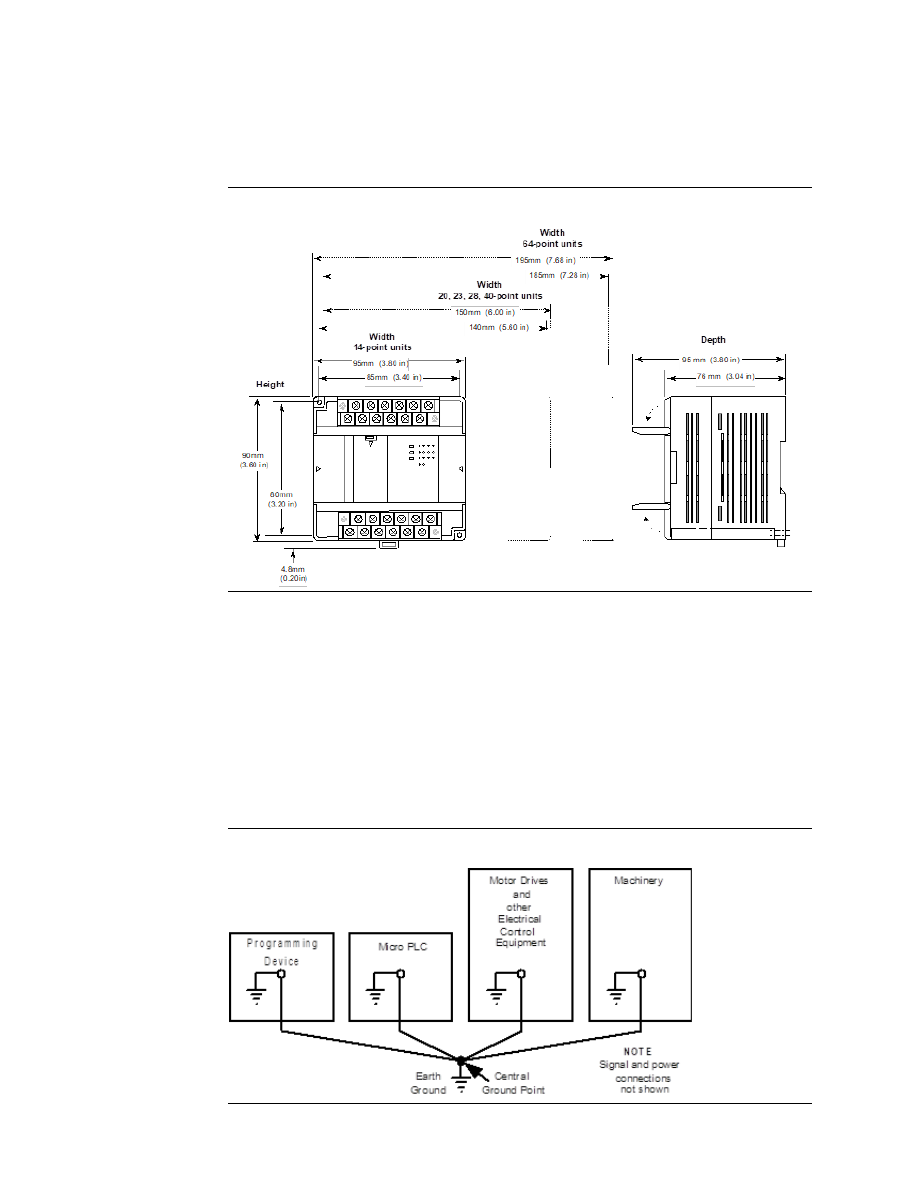
15.4.2


Dimensions of 14-, 20-, 23-, 28-, 40-, and 64-Point Micro 
PLCs and Expansion Units 

Figure 131 


15.5


Grounding the Equipment 

Equipment grounding procedures must be properly followed for safe operation of your PLC 
equipment.  

The  maximum  recommended  resistance  to  ground  is  200m

  (equivalent  to  100  feet  of 

AWG #12 

 3.29mm

2


 copper cable).  


Grounding installation must conform to National Electrical Code (NEC) standards. 


Ground conductors should be connected with separate branches routed to a central 
earth ground point. 

Figure 132 


User Manual 

Chapter 15 

GFK-1645M 

Dec 2019 


Installation Instructions 

275 


Ground conductors should be as short and as large in size as possible. Braided straps 
or  ground  cables 

  AWG  #12  (3.29mm

2

)  or  larger 

  can  be  used  to  minimize 

resistance. Conductors must always be large enough to carry the maximum short 
circuit current of the path being considered.  


Install an external earth leakage breaker and take other safety measures according 
to external wiring standards. 

15.5.1


Grounding the Programmer 

For  proper  operation,  the  computer  for  the  programming  software  must  have  a  ground 
connection  in  common  with  the  PLC.  Normally,  this  common  ground  connection  is 

provided by connecting the programmer’s power cord to the same power source (with the 

same  ground  reference  point)  as  the  PLC.  If  that  is  not  possible,  use  a  port  isolator 
(IC690ACC903) between the programmer PLC serial connection. If the programmer ground 
is at a different potential than the PLC ground, a shock hazard could exist. Also, damage to 
the ports or converter (if used) could occur when the programmer serial cable is connected 
between the two. 

 WARNING 

Failure to follow programmer grounding recommendations could result in personal injury, 
equipment damage, or both. 

15.6


Installing a PLC or Expansion Unit on a DIN Rail 

VersaMax  Nano  PLC  and  Micro  PLC  equipment  can  be  mounted  on  a  35mm  DIN  rail  as 
described below, or mounted on a metal panel using screws as described on the next page. 
The equipment must be mounted on a vertical surface. Do not mount it on a  horizontal 
surface. 

Figure 133 


The DIN rail must be electrically grounded to provide EMC protection as described on the 
next page. DIN rails compliant with DIN EN50032 are preferred.  

For  vibration  resistance,  the  DIN  rail  should  be  installed  on  a  panel  using  screws  spaced 
approximately 5.24cm (6 inches) apart. 


User Manual 

Chapter 15 

GFK-1645M 

Dec 2019 


Installation Instructions 

276 

15.6.1


Mounting the PLC on a DIN Rail 

Units mount on a 35 mm DIN rail as shown below. Using a small flat screwdriver or similar 
tool, pull out the retaining clip on the bottom of the unit. Press the unit back and release the 
retaining clip. Be sure the clip is holding the unit securely. 

Figure 134 


15.6.2


Removing the PLC from a DIN Rail 

Pull down the retaining clip on the bottom of the module then pull the unit away from the 
DIN rail. 

15.6.3


Panel-Mounting 

For greatest resistance to mechanical vibration and shock, units should be installed on a 
metal panel. 

Following the dimensions shown in this chapter or using the module itself as a template, 

mark  the  location  of  the  module’s  panel

-mount  holes  on  the  panel.  Drill  the  hole  in  the 

panel. Install the module using 65x70 M4 (#8-32) screws at least 20mm (0.79 in.) long in 
the panel-mount holes. 

Figure 135 


1.1  to  1.4Nm  (10  to  12  in/lbs)  of  torque  should  be  applied  to  M4  (#8-32)  steel  screws 
threaded  into  material  containing  internal  threads  and  having  a  minimum  thickness  of 
2.4mm (0.093in).  

User Manual 

Chapter 15 

GFK-1645M 

Dec 2019 


Installation Instructions 

277 

15.6.4


Grounding the Metal Panel or DIN Rail 

To prevent the risk of electric shock, the metal panel on which the PLC is installed must be 
properly grounded to protective earth.  

Connect the ground wire to the metal panel using a star washer. Where connections are 
made to a painted panel, the paint should be removed so clean, bare metal is exposed. 

Connect the metal plate, duct, pipe, door and sideboard etc. to protective earth. 

15.7


Connecting an Expansion Unit to a Micro PLC 

Up to four expansion units can be connected in series to a Micro PLC. 

CAUTION 

Power down the Micro PLC before connecting an Expansion Unit. Connecting an Expansion 
Unit with the Micro PLC powered up will damage the unit. 

Note: 

The Micro PLC and Expansion Unit(s) should be wired to a common power source and powered up 
together.  If  an  attached  Expansion  Unit  is  left  unpowered,  the  Micro  PLC  may  not  power  up 
properly. 

15.7.1


The Expansion Cable 

A 0.1-meter ribbon cable (IC200CBL501) is provided with each expansion unit. Cables are 
also  available  in  0.5-meter  (IC200CBL505)  and  1  meter  (IC200CBL510)  lengths.  The 
maximum  total  overall  length  is  2  meters.  This  cable  has  keyed  connectors  to  prevent 
incorrect  installation.  Powering  up  the  system  with  the  cable  improperly  installed  can 
damage  the  Expansion  Unit.  Do  not  substitute  a  different  cable.    If  you  need  to  order 
replacements, expansion cables are available in various lengths. Connect the units as shown 
below. 

Figure 136 


The  Expansion  Unit(s)  and  Micro  PLC  must  be  connected  in  the  same  orientation. 

Connecting an Expansion Unit “upside down” will damage the DC input circuit when the 

system is powered up. After installing the ribbon cable on a unit, close the hinged door. 

User Manual 

Chapter 15 

GFK-1645M 

Dec 2019 


Installation Instructions 

278 

15.8


System Wiring Guidelines 

In addition to the following wiring suggestions, we strongly urge that you follow all wiring 
and safety codes that apply to your area or to your type of equipment. Failure to do so could 
lead to personal injury or death, property damage or destruction, or both. 

Four types of wiring may be encountered in a typical factory installation: 


Power  wiring 

  the  plant  power  distribution,  and  high-power  loads  such  as  high 

horsepower motors. These circuits may be rated from tens to thousands of kVA at 
220Vac or higher. 


Control wiring 

 usually either low voltage DC or 120Vac of limited energy rating. 

Examples  are  wiring  to  start/stop  switches,  contactor  coils,  and  machine  limit 
switches. This is generally the interface level of discrete I/O. 


Analog wiring 

 transducer outputs and analog control voltages. This is the interface 

level to I/O analog blocks. 


Communications  and  signal  wiring 

  the  communications  network  that  ties 

everything together, including computer LANs, MAP, and field busses. 

These four types of wiring should be separated as much as possible to reduce the hazards 
from  insulation  failure,  miss-wiring,  and  interaction  (noise)  between  signals.  A  typical 
control system may require some mixing of the latter three types of wiring, particularly in 
cramped areas inside motor control centers and on control panels. 

Wiring  which  is  external  to  equipment  and  in  cable  trays  should  be  separated  following 
National Electrical Code practices. 

15.8.1


Safety Measures 

Appropriate emergency stop circuitry, interlock circuitry and similar safety measures should 
be added to the system in accordance with accepted practices. 

Appropriate  safety  measures  should  be  included  in  the  design  of  the  overall  system  to 
ensure safety in the event of incorrect, missing or abnormal signals caused by broken signal 
lines, momentary power interruptions or other causes. 

15.8.2


Installing Additional Suppression 

External MOV suppression can be installed at the power line input of a system enclosure (see 
below). The axial leaded ZA series of MOVs from Harris is often used. The MOV should be 
able to handle most line transients. Measurement of actual transients may be required in 
extreme cases to decide what MOV is best. 

Ideally, MOVs should be used at each cabinet in the system for maximum protection. The 
following  illustration  shows  suppression  on  both  power  lines  and  a  communications  bus 
entering an enclosure. 


User Manual 

Chapter 15 

GFK-1645M 

Dec 2019 


Installation Instructions 

279 

Figure 137 


Periodic Inspection and Replacement of MOVs 

MOVs do a good job of absorbing transients on communications, control, and power lines, 
provided  the  total  energy  of  those  transients  does  not  exceed  the  rating  of  the  device. 
However, if the energy of the transient exceeds the rating of the device, the MOV may be 
either damaged or destroyed. This failure may not be visibly or electrically evident. MOVs 
should be regularly inspected for signs of damage to assure continued protection against 
transients. For some applications, periodic replacement of critical MOVs is recommended, 
even if they do not show signs of damage. 

15.9


I/O Installation and Wiring 

Wiring diagrams are located in the individual module sections of this manual. 

 WARNING 


The PLC must be grounded to minimize electrical shock hazard. Failure to do so could 
result in injury to personnel. 


You should calculate the maximum current for each wire and observe proper wiring 
practices. Failure to do so could cause injury to personnel or damage to equipment. 


CAUTION 

When connecting stranded conductors, ensure that there are no projecting strands of 
wire. These could cause a short circuit, thereby damaging equipment or causing it to 
malfunction. 


User Manual 

Chapter 15 

GFK-1645M 

Dec 2019 


Installation Instructions 

280 

15.9.1


Wiring for Power Supply and I/O Connections 


Each  terminal  can  accept  solid  or  stranded  wires,  but  the  wires  into  any  given 
terminal must be of the same type and size.  


Use copper conductors rated for 75°C (167°F) for all wiring.  


Micro PLC wire sizes: one AWG #14 (2.1 mm

2

) conductor or two smaller conductors 

 AWG #16 (1.3 mm

2

) through AWG #20 (0.36mm2) per terminal. The suggested 

torque for the terminal connections is 5 in-lbs (5.76 kg-cm). 


Nano  PLC  wire  sizes:  each  terminal  accommodates  one  AWG  #14  (avg.  2.1mm

2


cross section) to AWG #22 wire (avg. 0.36mm

2

 cross section), or two wires up to 

AWG  #18  (avg.  0.86mm

2

  cross  section).  The  suggested  torque  for  the  terminal 

connections is 3 in-lbs (3.75 kg-cm). 

15.9.2


Removable Wiring Terminals 

Figure 138 


The terminal block assemblies of a Micro PLC can be removed to perform wiring. For 
example, a 14-point unit (shown above) has two removable terminal assemblies. 

CAUTION 

Do not insert or remove a terminal assembly with power applied to the PLC/Expansion Unit 
OR  TO  FIELD  DEVICES.  Injury  to  personnel  and  damage  to  the  equipment  may  result. 
Potentially dangerous voltages from field devices may be present on the screw terminals 
even though power to the PLC or Expansion Unit is turned off. Care must be taken any time 
you handle the removable terminal assembly, or any wires connected to it. 

A  new  Micro  PLC  or  Expansion  Unit  is  shipped  with  its  terminal  block  assemblies  firmly 
installed.  To  remove  a  terminal  assembly,  use  a  small  Phillips  or  flat  screwdriver  to 
alternately loosen the two captive retaining screws. Hold onto the terminal assembly; when 
the  screws  have  been  backed  out  of  the  holes,  the  terminal  assembly  is  completely 
detached from the module. 


User Manual 

Chapter 15 

GFK-1645M 

Dec 2019 


Installation Instructions 

281 

Figure 139 


When re-installing terminal assemblies, be sure to place each one in the correct location to 
avoid miss-wiring the module. The terminal assemblies are not keyed or labeled. 

15.9.3


General Wiring Procedures 

Follow the procedures below when routing and connecting field wiring from user devices to 
the PLC inputs and outputs. The individual PLC and Expansion Unit sections of this manual 
provide  detailed  wiring  information  for  connecting  input  and  output  devices  and  power 
sources. 


Turn off power to the PLC before connecting field wiring.  


All low-level signal wires should be run separately from other field wiring.  


All channels must be fed from the same phase for AC power lines. 


Install AC power cables and signal or data lines in separate cable trays or bunches 
from DC field wiring. 


Field wiring should not be routed close to any device that could be a potential source 
of electrical interference.  


Route the signal and data lines as close as possible to grounded surfaces such as 
cabinet elements, metal bars and cabinets panels. 


If severe noise problems are present, additional power supply filtering or an isolation 
transformer may be required.  


Ensure that proper grounding procedures are followed to minimize potential safety 
hazards to personnel.  


Label all wires to and from I/O devices. 


Do not attempt to disassemble, repair or modify any part of the PLC. 


Do not pull on cables or bend cables beyond their natural limit. The lines may break. 


Always use the power supply voltage listed in the module specifications. Using other 
voltages may damage the equipment. 


Do  not  apply  voltages  to  the  inputs  in  excess  of  the  rated  input  voltage.  The 
equipment may be damaged if the rated voltage is exceeded. 

User Manual 

Chapter 15 

GFK-1645M 

Dec 2019 


Installation Instructions 

282 


Do not use voltages with outputs in excess of the maximum switching capacity. The 
PLC may be damaged if the maximum switching capacity is exceeded. 


Use shielded cable for analog inputs and outputs and connect shields to a functional 
earth ground. 

Wiring Connections 

The following types of wiring terminals are recommended for use with VersaMax Micro PLC 
modules: 

Figure 140 


When using wiring terminals, be sure to tighten screws adequately, so the wiring terminals 
will not become loose. 

Alternatively, each module screw can accept: 


One wire, size AWG14 to AWG22 (2.1 to 0.36 mm2) or:  


Two wires, size AWG16 to AWG22 (1.3 to 0.36 mm2)  

Terminal Screws 

Should  any  of  the  terminal  screws  be  lost  or  damaged,  they  can  be  replaced  with  M3  x 
0.6mm pitch screws of the type shown below. 

Figure 141 


15.9.4


Providing Fusing for Outputs 

Outputs  with  electronic  short-circuit  protection  are  available  on  several  Micro  PLCs  and 
Expansion Units. All other module outputs should be externally fused (1 Amp to 2 Amp fuse) 
to  protect  the  output  point  contacts.  For  lighter  loads,  the  internal  common  fuse  (3.15 
Amp) can be replaced with a 1 amp fuse to protect the output point without adding the 
external fusing. 


User Manual 

Chapter 15 

GFK-1645M 

Dec 2019 


Installation Instructions 

283 

15.9.5


Providing Suppression Circuits for Inductive Loads 

Figure 142: Typical Relay Output Circuit 


Installing suitable suppression across inductive loads enhances reliability of relay contacts. 
When switching inductive loads, relay contact life approaches resistive load contact life if 
suppression circuits are used. The 1A, 100V diode shown in the typical DC load suppression 
circuit is an industry standard 1N4934.  


15.9.6


Typical DC Input Circuits 

All DC inputs can be connected as either positive or negative logic. 

Figure 143: Typical 12/24Vdc Positive/Negative Logic Input Circuit 


User Manual 

Chapter 15 

GFK-1645M 

Dec 2019 


Installation Instructions 

284 

Positive and Negative Logic Definitions  

The IEC definitions for positive logic and negative logic, as applied to the PLC I/O circuits, are 
shown below.  

Input Points

 Positive Logic  


Equivalent to IEC sink input points. 


Sink current from the input device to 
the user common or negative power 
bus. 

The input device is connected between the 
positive power bus and the input terminal. The 
negative bus is connected to the input circuit 
common. 

Input Points 

 Negative Logic  


Equivalent to IEC source inputs. 


Source current through the input device 
to the user common or positive power 
bus. 

The input device is connected between the 
negative power bus and the input terminal. The 
positive bus is connected to the input circuit 
common. 

15.9.7


Typical DC Output Circuits 

Typical Transistor Output Circuit 12Vdc 

Figure 144 


User Manual 

Chapter 15 

GFK-1645M 

Dec 2019 


Installation Instructions 

285 

Typical Transistor Output Circuit 24Vdc 

Figure 145 


For Micro 10-, 14-, 23- and 28- PLCs, when using the outputs as PWM or Pulse Train Outputs, 
and  for  duty  cycles  in  the  lower  ranges  (5%  and  lower),  a  pulldown  resistor  must  be 
connected between the output point (Q1-Q3) and the common terminal (C1). A 1.5 k

Ω, 

0.5-watt resistor is recommended. 

Micro 20-, 40-, and 64- PLCs do not require a pulldown resistor. 

Output Points 

 Positive Logic 

Figure 146 


Equivalent to IEC source output points. 


Source current to the loads from the user common or positive power bus.  

The load is connected between the negative power bus and the module output. 


User Manual 

Chapter 15 

GFK-1645M 

Dec 2019 


Installation Instructions 

286 

Output Points 

 Negative Logic 

Figure 147 


Equivalent to IEC sink output points 


Load is connected between positive power bus and module output. 

15.9.8


Typical High-Speed Counter Connections 

High-Speed Counter Circuit 

 Positive Logic Connection 

Figure 148 


High-Speed Counter Circuit 

 Negative Logic Connection 

Figure 149 


User Manual 

Chapter 15 

GFK-1645M 

Dec 2019 


Installation Instructions 

287 

When I1-I6 on a Micro PLC are used as High-Speed Counter inputs, the input switches should 
be  solid  state  to  prevent  switch  bouncing,  which  could  cause  unintended  High-Speed 
counter counts or strobe input signals. 

15.9.9


Added Resistance for 20-, 40-, and 64-Point Micro PLCS 
at Higher Count Rates 

When using count rates about 30kHz on a 20-, 40-, or 64-Point Micro PLC, a 1k

, 3W resistor 

should added between the common and the Count input as shown below. 

High-Speed Counter Circuit 

 Positive Logic Connection 

Figure 150 


High-Speed Counter Circuit 

 Negative Logic Connection 

Figure 151 


User Manual 

Chapter 15 

GFK-1645M 

Dec 2019 


Installation Instructions 

288 

15.9.10


Typical AC Input and Output Circuits 

Typical 120Vac Input Circuit 

Figure 152 


Typical 120/240Vac Triac Output Circuit 

Figure 153 


User Manual 

Chapter 15 

GFK-1645M 

Dec 2019 


Installation Instructions 

289 

15.9.11


Typical Analog Input and Output Circuits 

Analog Input Circuit 

Figure 154 


Analog Output Circuit 

Figure 155 


Content      ..     18      19      20      21     ..