HUSQVARNA FC 250. OWNER'S MANUAL (2024) - page 3
SERVICE WORK ON THE CHASSIS
11
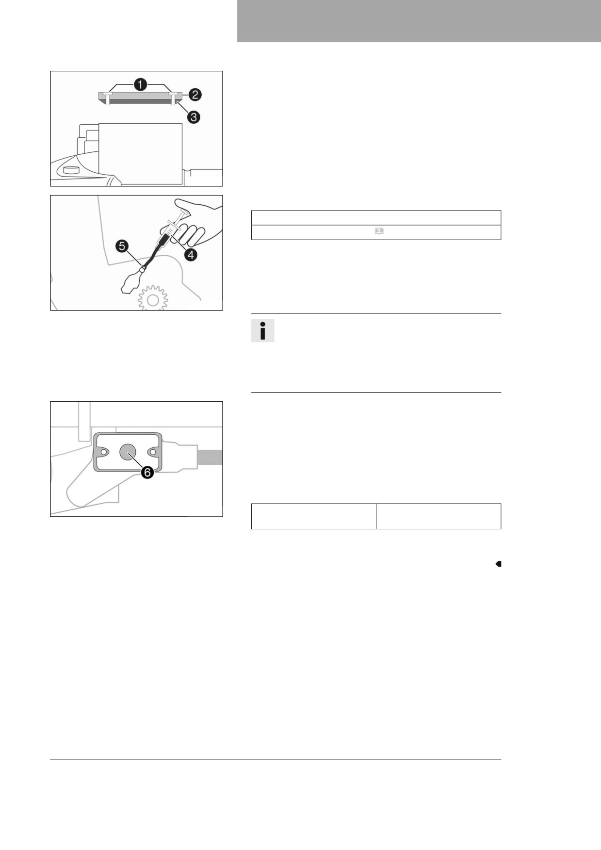
– Move the hydraulic clutch fluid reservoir mounted on the han-
dlebar into a horizontal position.
- Remove screws 1.
- Take off cover 2 with membrane 3.
H04933-10
-
Fill bleeding syringe 4 with the appropriate hydraulic fluid.
Syringe (50329050000)
Brake fluid DOT 4 / DOT 5.1 ( p. 140)
-
On the clutch slave cylinder, remove the protection cap and
mount bleeding syringe 4 with an appropriate hose piece
on bleeder screw 5.
-
Only loosen bleeder screw 5 on the clutch slave cylinder to
the point where filling is possible.
H04934-10
Info
Use water to immediately clean up any brake fluid that
has overflowed or spilled.
Avoid contact between brake fluid and painted parts.
Brake fluid corrodes paint.
Only use clean brake fluid from a sealed container.
-
Now press the fluid into the system until it emerges from
hole 6 of the master cylinder without bubbles.
-
Occasionally extract the fluid from the master cylinder reser-
voir to prevent overflowing.
-
Tighten the bleeder screw and remove the bleeding syringe
with the hose. Mount the protection cap.
-
Correct the fluid level of the hydraulic clutch.
Guideline
H04932-10
Fluid level below container
4 mm (0.16 in)
rim
-
Position the cover with the membrane. Mount and tighten the
screws.
81
12
BRAKE SYSTEM
12.1
Checking the free travel of the hand brake lever
Warning
Danger of accidents The brake system fails in the event of overheating.
If there is no free travel on the hand brake lever, pressure builds up on the front brake circuit.
-
Set the free travel on the hand brake lever in accordance with the specification.
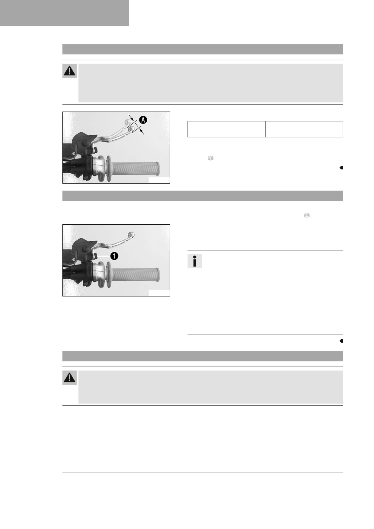
- Push the hand brake lever forward and check free travel A.
Free travel of hand brake
≥ 3 mm (≥ 0.12 in)
lever
» If the free travel does not match the specification:
- Adjust basic position of the hand brake lever.
(
p. 82)
F03649-10
12.2
Adjusting the basic position of the hand brake lever
Preparatory work
- Check the free travel of the hand brake lever. ( p. 82)
Main work
- Adjust basic position of the hand brake lever to your hand
size by turning adjusting screw 1.
Info
Turn the adjusting screw clockwise to increase the
distance between the hand brake lever and the han-
dlebar.
Turn the adjusting screw counterclockwise to
F03648-12
decrease the distance between the hand brake lever
and the handlebar.
The range of adjustment is limited.
Only turn the adjusting screw by hand, and do not use
force.
Do not make any adjustments while riding.
12.3
Checking the brake discs
Warning
Danger of accidents Worn-out brake discs reduce the braking effect.
- Make sure that worn-out brake discs are replaced immediately. (Your authorized Husqvarna Motor-
cycles workshop will be glad to help.)
82
BRAKE SYSTEM 12
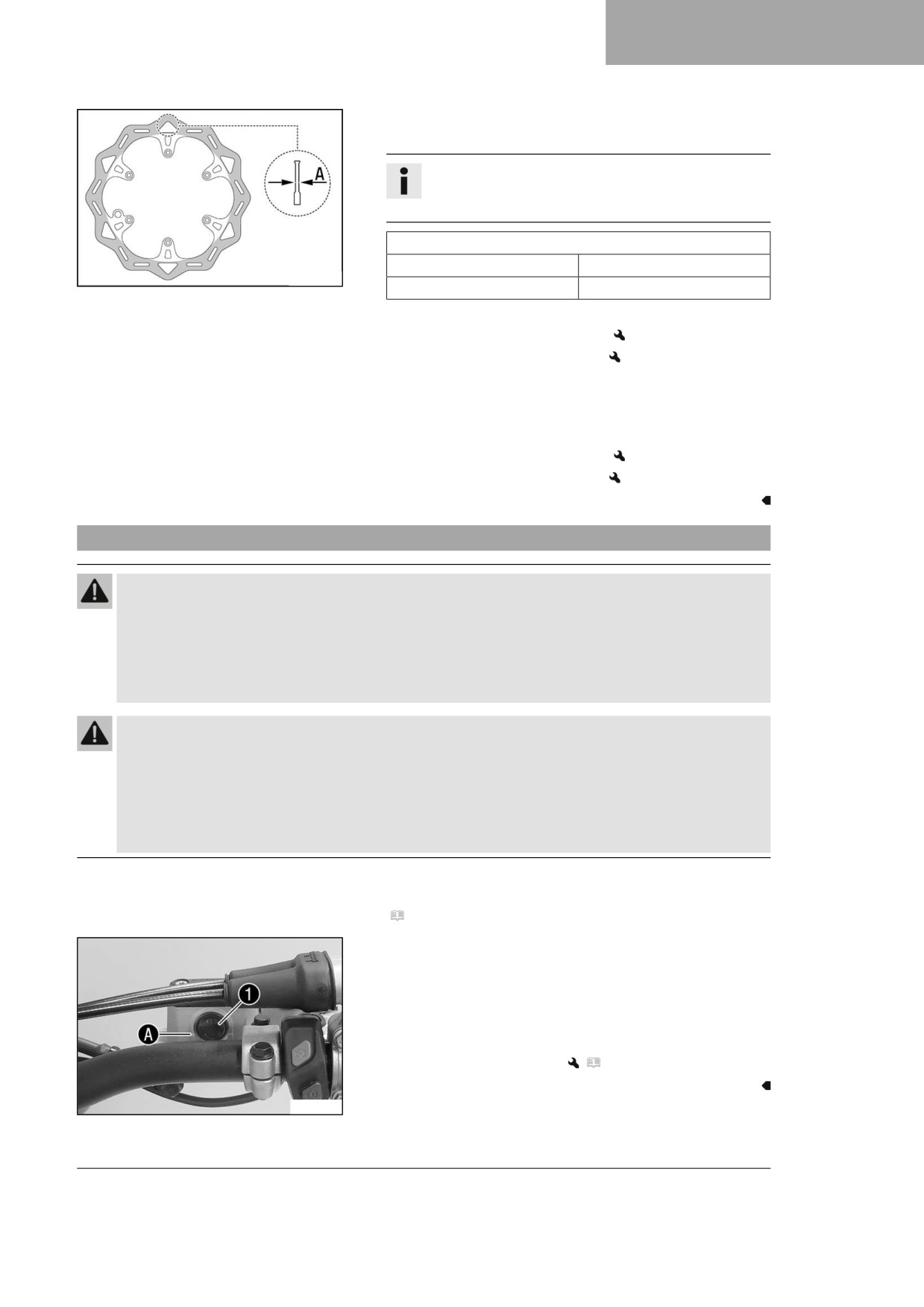
- Check the front and rear brake disc thickness at multiple
points for the dimension A.
Info
Wear reduces the thickness of the brake disc around
the contact surface of the brake linings.
Brake discs - wear limit
front
2.5 mm (0.098 in)
H00938-10
rear
3.5 mm (0.138 in)
» If the brake disc thickness is less than the specification:
- Change the front brake disc.
- Change the rear brake disc.
- Check the front and rear brake discs for damage, cracking,
and deformation.
» If the brake disc exhibits damage, cracking, or deforma-
tion:
- Change the front brake disc.
- Change the rear brake disc.
12.4
Checking the front brake fluid level
Warning
Danger of accidents An insufficient brake fluid level will cause the brake system to fail.
If the brake fluid level drops below the specified marking or the specified value, the brake system is
leaking or the brake linings are worn down.
- Check the brake system and do not continue riding until the problem is eliminated. (Your authorized
Husqvarna Motorcycles workshop will be glad to help.)
Warning
Danger of accidents Brake fluid which is too old or of the wrong type impairs the function of the
brake system.
- Make sure that brake fluid for the front and rear brake is changed in accordance with the service
schedule. (Your authorized Husqvarna Motorcycles workshop will be glad to help.)
- Make sure that only clean, approved brake fluid from a tightly sealed container is used. (Your autho-
rized Husqvarna Motorcycles workshop will be glad to help.)
Preparatory work
- Check that the brake linings of the front brake are secured.
(
p. 85)
Main work
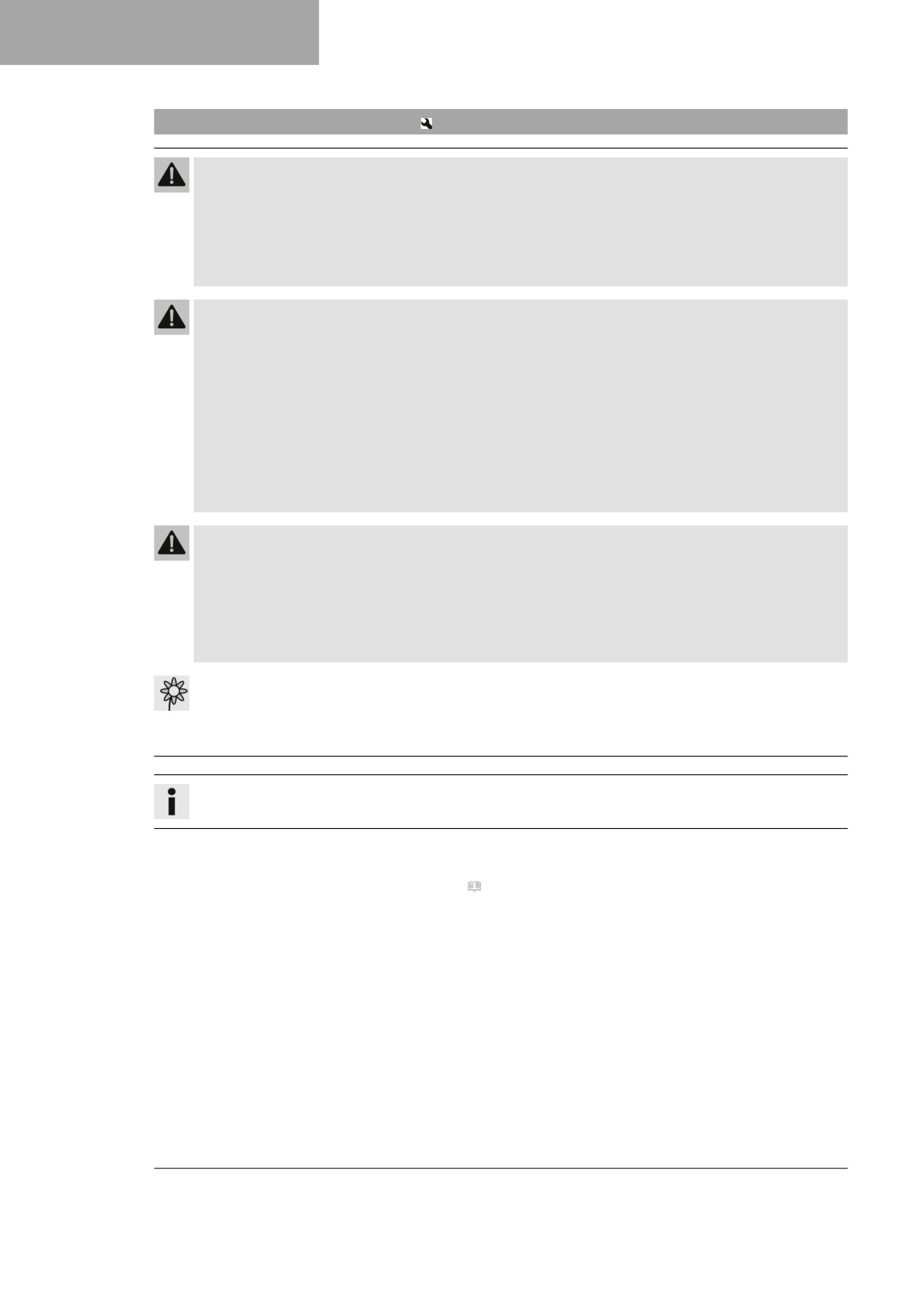
- Move the brake reservoir mounted on the handlebar to a hori-
zontal position.
- Check the brake fluid level in level viewer 1.
» If the brake fluid level has dropped below the
marking A:
- Add front brake fluid.
(
p. 84)
F03689-10
83
12
BRAKE SYSTEM
12.5
Adding front brake fluid
Warning
Danger of accidents An insufficient brake fluid level will cause the brake system to fail.
If the brake fluid level drops below the specified marking or the specified value, the brake system is
leaking or the brake linings are worn down.
- Check the brake system and do not continue riding until the problem is eliminated. (Your authorized
Husqvarna Motorcycles workshop will be glad to help.)
Warning
Skin irritation Brake fluid is a harmful substance.
- Keep brake fluid out of the reach of children.
- Wear suitable protective clothing and safety glasses.
- Do not allow brake fluid to come into contact with the skin, the eyes or clothing.
- Consult a doctor immediately if brake fluid has been swallowed.
- Rinse the affected area with plenty of water in the event of contact with the skin.
- Rinse eyes thoroughly with water immediately and consult a doctor if brake fluid comes into contact
with the eyes.
- If brake fluid spills on to your clothing, change the clothing.
Warning
Danger of accidents Brake fluid which is too old or of the wrong type impairs the function of the
brake system.
- Make sure that brake fluid for the front and rear brake is changed in accordance with the service
schedule. (Your authorized Husqvarna Motorcycles workshop will be glad to help.)
- Make sure that only clean, approved brake fluid from a tightly sealed container is used. (Your autho-
rized Husqvarna Motorcycles workshop will be glad to help.)
Note
Environmental hazard Hazardous substances cause environmental damage.
- Dispose of oils, grease, filters, fuel, cleaning agents, brake fluid, etc., correctly and in compliance
with the applicable regulations.
Info
Avoid contact between brake fluid and painted parts. Brake fluid corrodes paint.
Preparatory work
- Check that the brake linings of the front brake are secured.
(
p. 85)
84
BRAKE SYSTEM 12
Main work
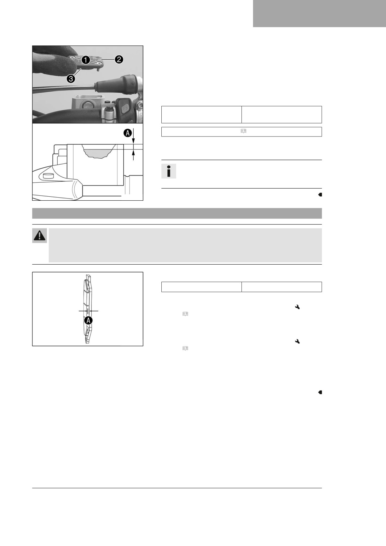
- Move the brake fluid reservoir mounted on the handlebar to a
horizontal position.
- Remove screws 1.
- Take off cover 2 with membrane 3.
- Add brake fluid to level A.
Guideline
5 mm (0.2 in)
Level A (brake fluid level
below reservoir rim)
Brake fluid DOT 4 / DOT 5.1 ( p. 140)
- Position cover 2 with membrane 3. Mount and tighten
screws 1.
Info
Use water to immediately clean up any brake fluid that
has overflowed or spilled.
F03694-10
12.6
Checking that the brake linings of the front brake are secured
Warning
Danger of accidents Worn-out brake linings reduce the braking effect.
- Ensure that worn-out brake linings are replaced immediately. (Your authorized Husqvarna Motorcy-
cles workshop will be glad to help.)
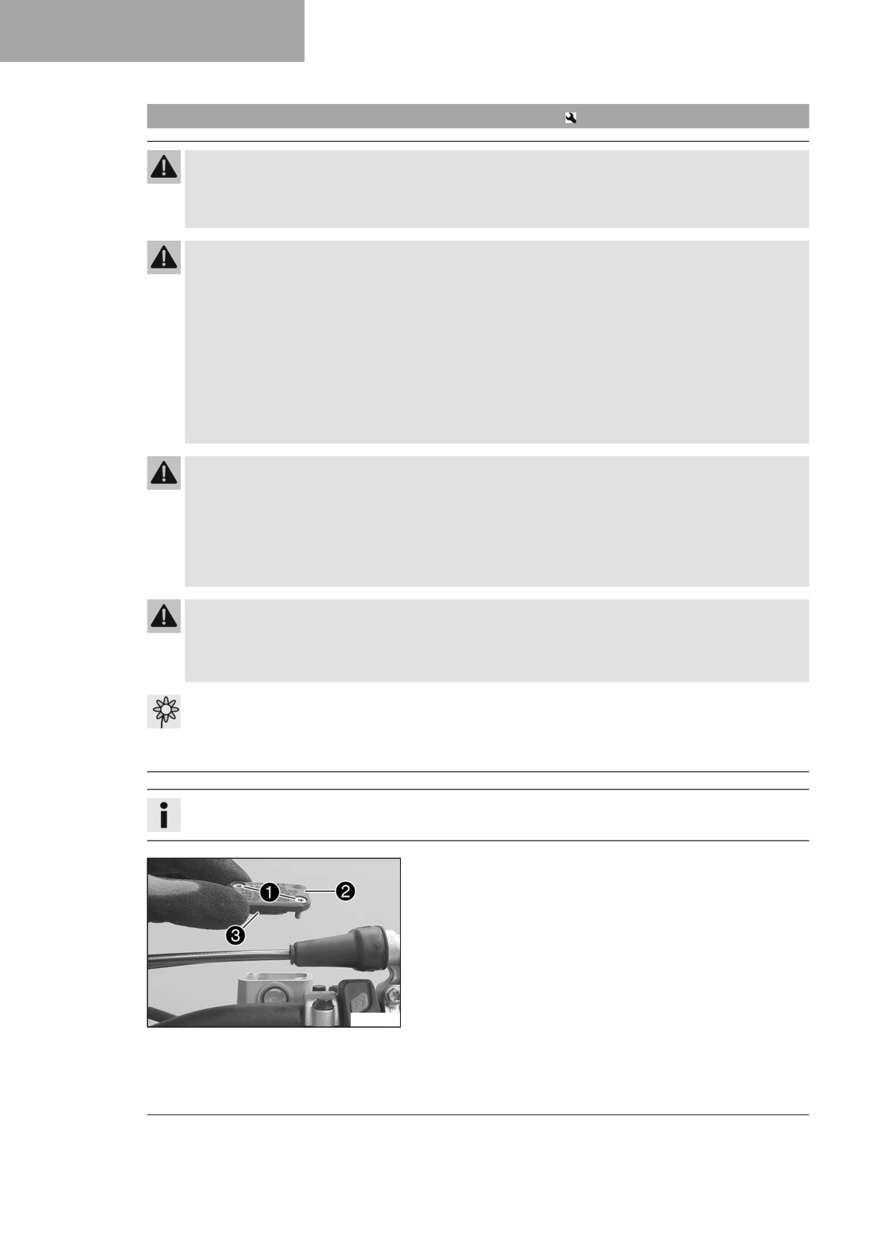
- Check the brake linings for minimum thickness A.
Minimum thickness A
≥ 1 mm (≥ 0.04 in)
» If the minimum thickness is less than specified:
- Change the brake linings of the front brake.
(
p. 86)
– Check the brake linings for damage and cracking.
» If damage or wear is encountered:
M02047-10
- Change the brake linings of the front brake.
(
p. 86)
– Check that the brake linings are secured.
» If the brake linings are not secured correctly:
- Secure brake linings, replace with new parts if neces-
sary.
85
12
BRAKE SYSTEM
12.7
Changing the brake linings of the front brake
Warning
Danger of accidents Incorrect servicing will cause the brake system to fail.
- Ensure that service work and repairs are performed professionally. (Your authorized
Husqvarna Motorcycles workshop will be glad to help.)
Warning
Skin irritation Brake fluid is a harmful substance.
- Keep brake fluid out of the reach of children.
- Wear suitable protective clothing and safety glasses.
- Do not allow brake fluid to come into contact with the skin, the eyes or clothing.
- Consult a doctor immediately if brake fluid has been swallowed.
- Rinse the affected area with plenty of water in the event of contact with the skin.
- Rinse eyes thoroughly with water immediately and consult a doctor if brake fluid comes into contact
with the eyes.
- If brake fluid spills on to your clothing, change the clothing.
Warning
Danger of accidents Brake fluid which is too old or of the wrong type impairs the function of the
brake system.
- Make sure that brake fluid for the front and rear brake is changed in accordance with the service
schedule. (Your authorized Husqvarna Motorcycles workshop will be glad to help.)
- Make sure that only clean, approved brake fluid from a tightly sealed container is used. (Your autho-
rized Husqvarna Motorcycles workshop will be glad to help.)
Warning
Danger of accidents Oil or grease on the brake discs reduces the braking effect.
- Always keep the brake discs free of oil and grease.
- Clean the brake discs with brake cleaner when necessary.
Note
Environmental hazard Hazardous substances cause environmental damage.
- Dispose of oils, grease, filters, fuel, cleaning agents, brake fluid, etc., correctly and in compliance
with the applicable regulations.
Info
Avoid contact between brake fluid and painted parts. Brake fluid corrodes paint.
- Move the brake fluid reservoir mounted on the handlebar to a
horizontal position.
- Remove screws 1.
- Take off cover 2 with membrane 3.
F03690-10
86
BRAKE SYSTEM 12
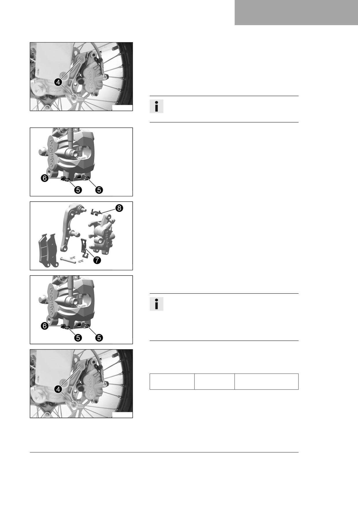
- Remove screws 4.
- Press back the brake linings by slightly tilting the brake
caliper laterally on the brake disc. Carefully pull the brake
caliper up and off the brake disc.
- Press the brake piston back into the basic position and
ensure that brake fluid does not flow out of the brake fluid
reservoir; extract some if necessary.
Info
A01183-10
Do not operate the hand brake lever if the brake
caliper has been removed.
- Remove cotter pins 5, pull out pin 6, and remove the
brake linings.
- Clean the brake caliper and the brake caliper bracket.
F03696-10
- Check that spring plate 7 in the brake caliper and brake
pad sliding plate 8 in the brake caliper bracket are seated
correctly.
F03692-10
- Insert the new brake linings, insert pin 6, and mount cotter
pins 5.
Info
Always change the brake linings in pairs.
To make it easier to mount the pin, push the brake
linings against the retainer spring.
Make sure the brake linings and retainer spring are
seated correctly.
F03696-10
- Position the brake caliper.
- Mount and tighten screws 4.
Guideline
Screw, front
M8
25 Nm (18.4 lbf ft)
brake caliper
Loctite®243™
– Operate the hand brake lever repeatedly until the brake lin-
ings are in contact with the brake disc and there is a pressure
point.
A01184-10
87
12
BRAKE SYSTEM
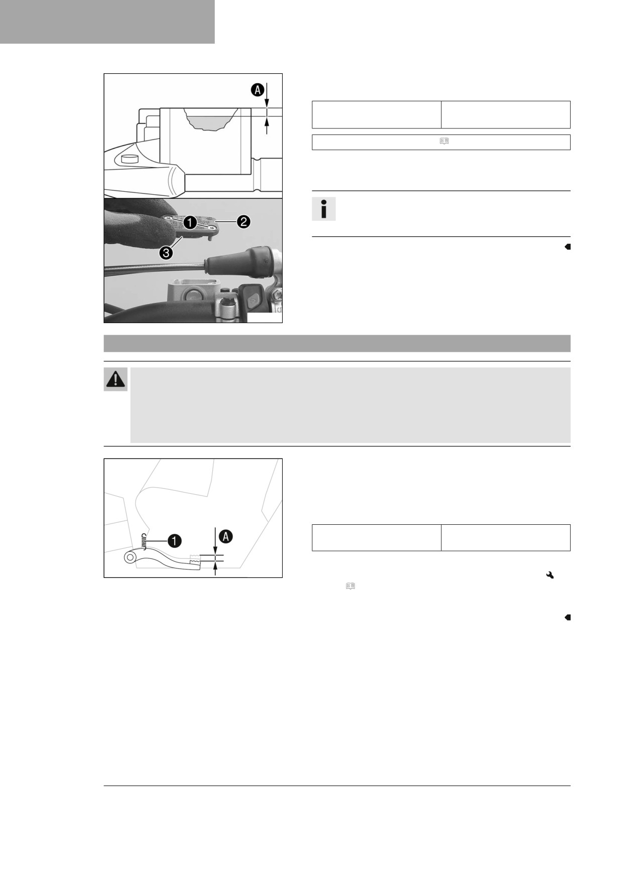
- Add brake fluid up to level A.
Guideline
5 mm (0.2 in)
Level A (brake fluid level
below reservoir rim)
Brake fluid DOT 4 / DOT 5.1 ( p. 140)
- Position cover 2 with membrane 3.
- Mount and tighten screws 1.
Info
Use water to immediately clean up any brake fluid that
has overflowed or spilled.
F03693-10
12.8
Checking the free travel of foot brake lever
Warning
Danger of accidents The brake system fails in the event of overheating.
If there is no free travel on the foot brake lever, pressure builds up in the brake system on the rear
brake.
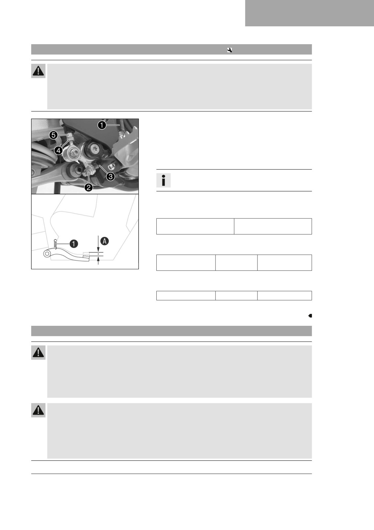
- Set the free travel on the foot brake lever in accordance with the specification.
- Disconnect spring 1.
- Move the foot brake lever back and forth between the end
stop and the contact to the foot brake cylinder piston and
check free travel A.
Guideline
Free travel at foot brake
3 … 5 mm (0.12 … 0.2 in)
lever
» If the free travel does not meet specifications:
402026-10
- Adjust the basic position of the foot brake lever.
(
p. 89)
– Reconnect spring 1.
88
BRAKE SYSTEM 12
12.9
Adjusting the basic position of the foot brake lever
Warning
Danger of accidents The brake system fails in the event of overheating.
If there is no free travel on the foot brake lever, pressure builds up in the brake system on the rear
brake.
-
Set the free travel on the foot brake lever in accordance with the specification.
- Detach spring 1.
- Loosen nut 4 and, with push rod 5, turn it back until you
have maximum free travel.
- To adjust the basic position of the foot brake lever to individ-
ual requirements, loosen nut 2 and turn screw 3 accord-
ingly.
Info
The range of adjustment is limited.
- Turn push rod 5 accordingly until you have free travel A. If
necessary, adjust the basic position of the foot brake lever.
Guideline
Free travel at foot brake
3 … 5 mm (0.12 … 0.2 in)
lever
- Hold push rod 5 and tighten nut 4.
Guideline
Remaining nuts,
M6
10 Nm (7.4 lbf ft)
V01355-10
chassis
- Hold screw 3 and tighten nut 2.
Guideline
Brake lever stop nut
M8
20 Nm (14.8 lbf ft)
– Attach spring 1.
12.10
Checking the rear brake fluid level
Warning
Danger of accidents An insufficient brake fluid level will cause the brake system to fail.
If the brake fluid level drops below the specified marking or the specified value, the brake system is
leaking or the brake linings are worn down.
- Check the brake system and do not continue riding until the problem is eliminated. (Your authorized
Husqvarna Motorcycles workshop will be glad to help.)
Warning
Danger of accidents Brake fluid which is too old or of the wrong type impairs the function of the
brake system.
- Make sure that brake fluid for the front and rear brake is changed in accordance with the service
schedule. (Your authorized Husqvarna Motorcycles workshop will be glad to help.)
- Make sure that only clean, approved brake fluid from a tightly sealed container is used. (Your autho-
rized Husqvarna Motorcycles workshop will be glad to help.)
89
12
BRAKE SYSTEM
Preparatory work
- Check that the brake linings of the rear brake are secured.
(
p. 91)
Main work
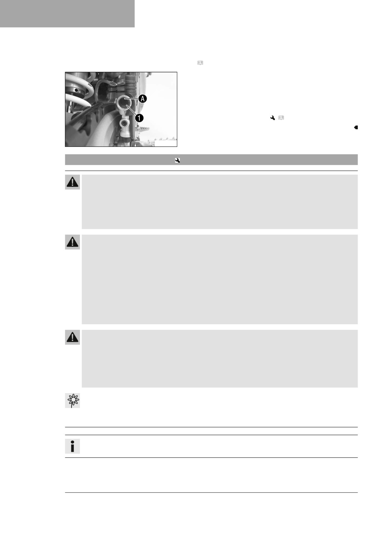
- Stand the vehicle upright.
- Check the brake fluid level in level viewer 1.
» If the brake fluid level has dropped below the
marking A:
- Add rear brake fluid.
(
p. 90)
A01084-10
12.11
Adding rear brake fluid
Warning
Danger of accidents An insufficient brake fluid level will cause the brake system to fail.
If the brake fluid level drops below the specified marking or the specified value, the brake system is
leaking or the brake linings are worn down.
- Check the brake system and do not continue riding until the problem is eliminated. (Your authorized
Husqvarna Motorcycles workshop will be glad to help.)
Warning
Skin irritation Brake fluid is a harmful substance.
- Keep brake fluid out of the reach of children.
- Wear suitable protective clothing and safety glasses.
- Do not allow brake fluid to come into contact with the skin, the eyes or clothing.
- Consult a doctor immediately if brake fluid has been swallowed.
- Rinse the affected area with plenty of water in the event of contact with the skin.
- Rinse eyes thoroughly with water immediately and consult a doctor if brake fluid comes into contact
with the eyes.
- If brake fluid spills on to your clothing, change the clothing.
Warning
Danger of accidents Brake fluid which is too old or of the wrong type impairs the function of the
brake system.
- Make sure that brake fluid for the front and rear brake is changed in accordance with the service
schedule. (Your authorized Husqvarna Motorcycles workshop will be glad to help.)
- Make sure that only clean, approved brake fluid from a tightly sealed container is used. (Your autho-
rized Husqvarna Motorcycles workshop will be glad to help.)
Note
Environmental hazard Hazardous substances cause environmental damage.
- Dispose of oils, grease, filters, fuel, cleaning agents, brake fluid, etc., correctly and in compliance
with the applicable regulations.
Info
Avoid contact between brake fluid and painted parts. Brake fluid corrodes paint.
90
BRAKE SYSTEM 12
Preparatory work
- Check that the brake linings of the rear brake are secured.
(
p. 91)
– Remove the right side panel. ( p. 67)
- Remove the frame protector. ( p. 51)
Main work
- Stand the vehicle upright.
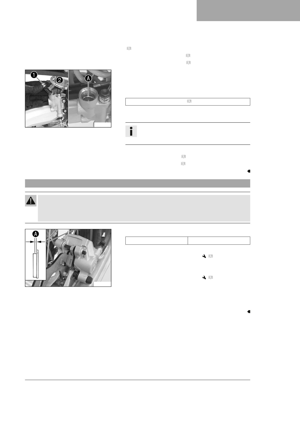
- Remove screw cap 1 with membrane 2 and the O-ring.
- Add brake fluid up to the marking A.
Brake fluid DOT 4 / DOT 5.1 ( p. 140)
- Mount and tighten the screw cap with the membrane and O-
ring.
T04401-01
Info
Use water to immediately clean up any brake fluid that
has overflowed or spilled.
Finishing work
- Install the frame protector. ( p. 52)
- Install the right side panel. ( p. 67)
12.12
Checking that the brake linings of the rear brake are secured
Warning
Danger of accidents Worn-out brake linings reduce the braking effect.
- Ensure that worn-out brake linings are replaced immediately. (Your authorized Husqvarna Motorcy-
cles workshop will be glad to help.)
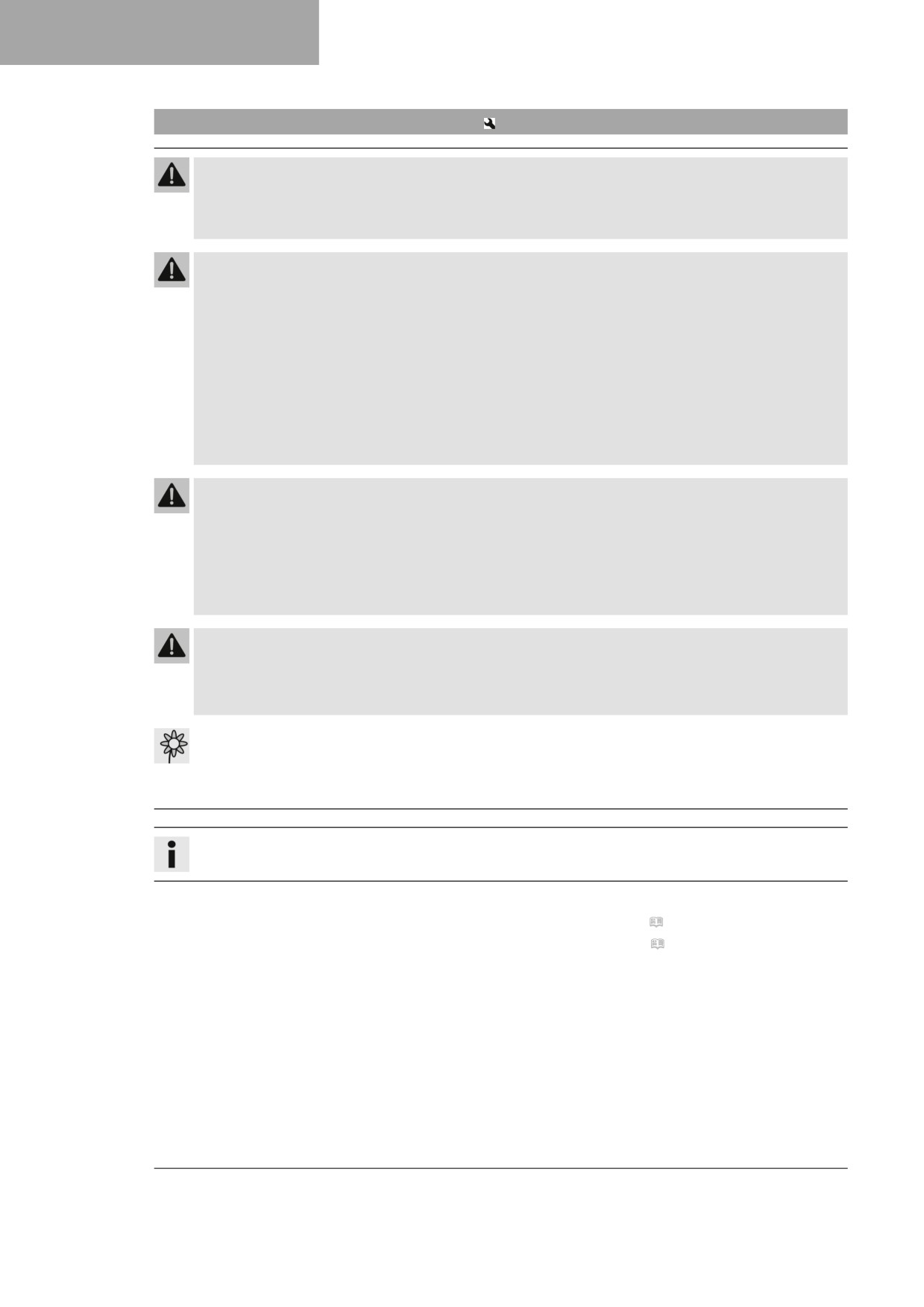
- Check the brake linings for minimum thickness A.
≥ 1 mm (≥ 0.04 in)
Minimum thickness A
» If the minimum thickness is less than specified:
- Change the rear brake linings.
(
p. 92)
– Check the brake linings for damage and cracking.
» If damage or wear is encountered:
- Change the rear brake linings.
(
p. 92)
H00322-10
- Check that the brake linings are secured.
» If the brake linings are not secured correctly:
- Secure brake linings, replace with new parts if neces-
sary.
91
12
BRAKE SYSTEM
12.13
Changing the rear brake linings
Warning
Danger of accidents Incorrect servicing will cause the brake system to fail.
- Ensure that service work and repairs are performed professionally. (Your authorized
Husqvarna Motorcycles workshop will be glad to help.)
Warning
Skin irritation Brake fluid is a harmful substance.
- Keep brake fluid out of the reach of children.
- Wear suitable protective clothing and safety glasses.
- Do not allow brake fluid to come into contact with the skin, the eyes or clothing.
- Consult a doctor immediately if brake fluid has been swallowed.
- Rinse the affected area with plenty of water in the event of contact with the skin.
- Rinse eyes thoroughly with water immediately and consult a doctor if brake fluid comes into contact
with the eyes.
- If brake fluid spills on to your clothing, change the clothing.
Warning
Danger of accidents Brake fluid which is too old or of the wrong type impairs the function of the
brake system.
- Make sure that brake fluid for the front and rear brake is changed in accordance with the service
schedule. (Your authorized Husqvarna Motorcycles workshop will be glad to help.)
- Make sure that only clean, approved brake fluid from a tightly sealed container is used. (Your autho-
rized Husqvarna Motorcycles workshop will be glad to help.)
Warning
Danger of accidents Oil or grease on the brake discs reduces the braking effect.
- Always keep the brake discs free of oil and grease.
- Clean the brake discs with brake cleaner when necessary.
Note
Environmental hazard Hazardous substances cause environmental damage.
- Dispose of oils, grease, filters, fuel, cleaning agents, brake fluid, etc., correctly and in compliance
with the applicable regulations.
Info
Avoid contact between brake fluid and painted parts. Brake fluid corrodes paint.
Preparatory work
- Remove the right side panel. ( p. 67)
- Remove the frame protector. ( p. 51)
92
BRAKE SYSTEM 12
Main work
- Stand the vehicle upright.
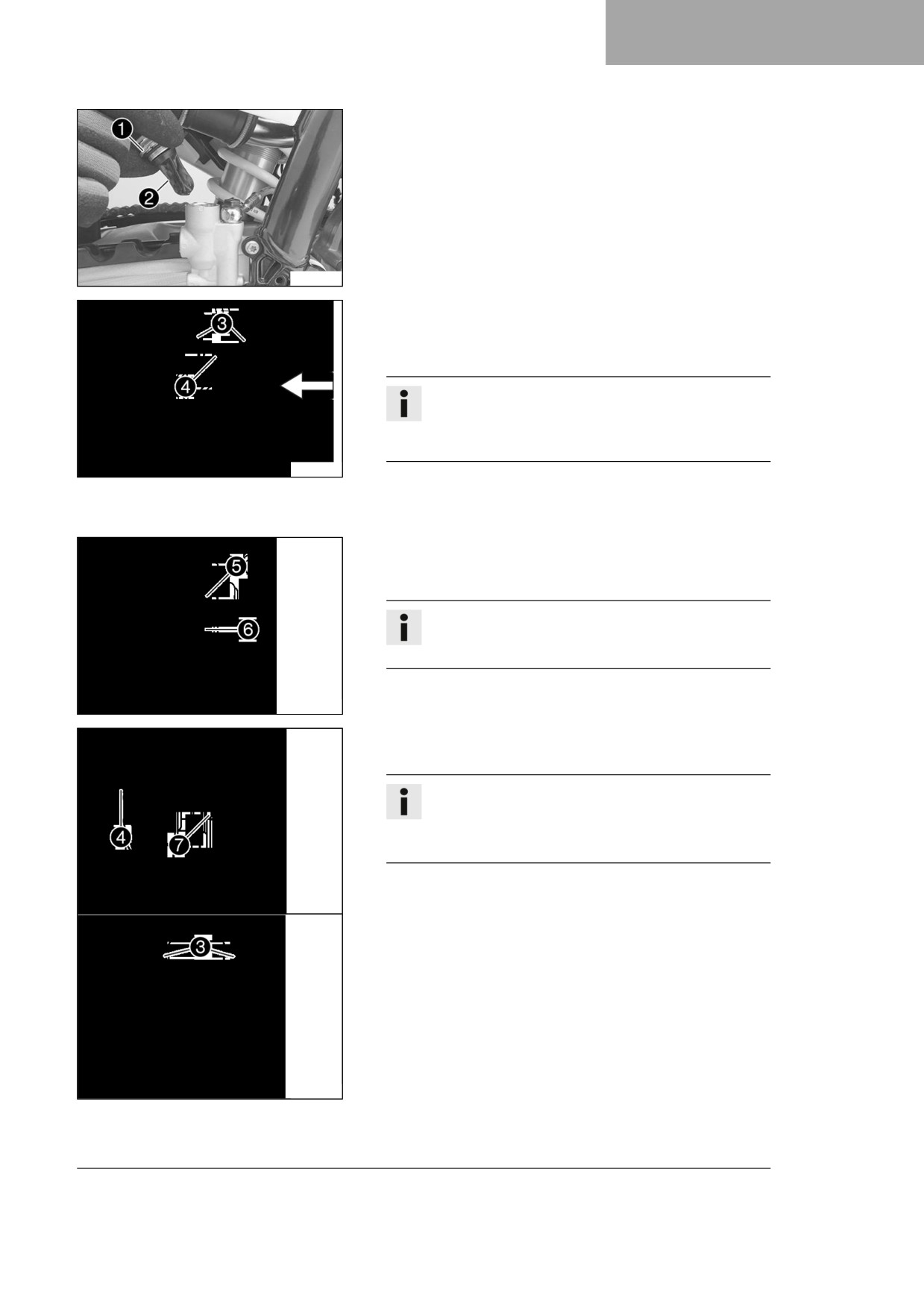
- Remove screw cap 1 with membrane 2 and the O-ring.
T04402-10
-
Manually press the brake caliper toward the brake disc to
push back the brake piston. Ensure that brake fluid does not
flow out of the brake fluid reservoir; extract some if neces-
sary.
Info
Make sure that you do not press the brake caliper
against the spokes when pushing back the brake pis-
ton.
J00084-10
-
Remove cotter pins 3, pull out pin 4, and remove the
brake linings.
-
Clean the brake caliper and the brake caliper bracket.
–
Check that spring plate 5 in the brake caliper and brake
pad sliding plate 6 in the brake caliper bracket are seated
correctly.
Info
The arrow on the spring plate points in the direction of
rotation of the brake disc.
J00085-10
-
Insert the new brake linings, insert pin 4, and mount cotter
pins 3.
Info
Always change the brake linings in pairs.
Make sure that decoupling plate 7 is mounted on
the piston side brake lining.
-
Operate the foot brake lever repeatedly until the brake lin-
ings are in contact with the brake disc and there is a pressure
point.
J00088-10
93
12
BRAKE SYSTEM
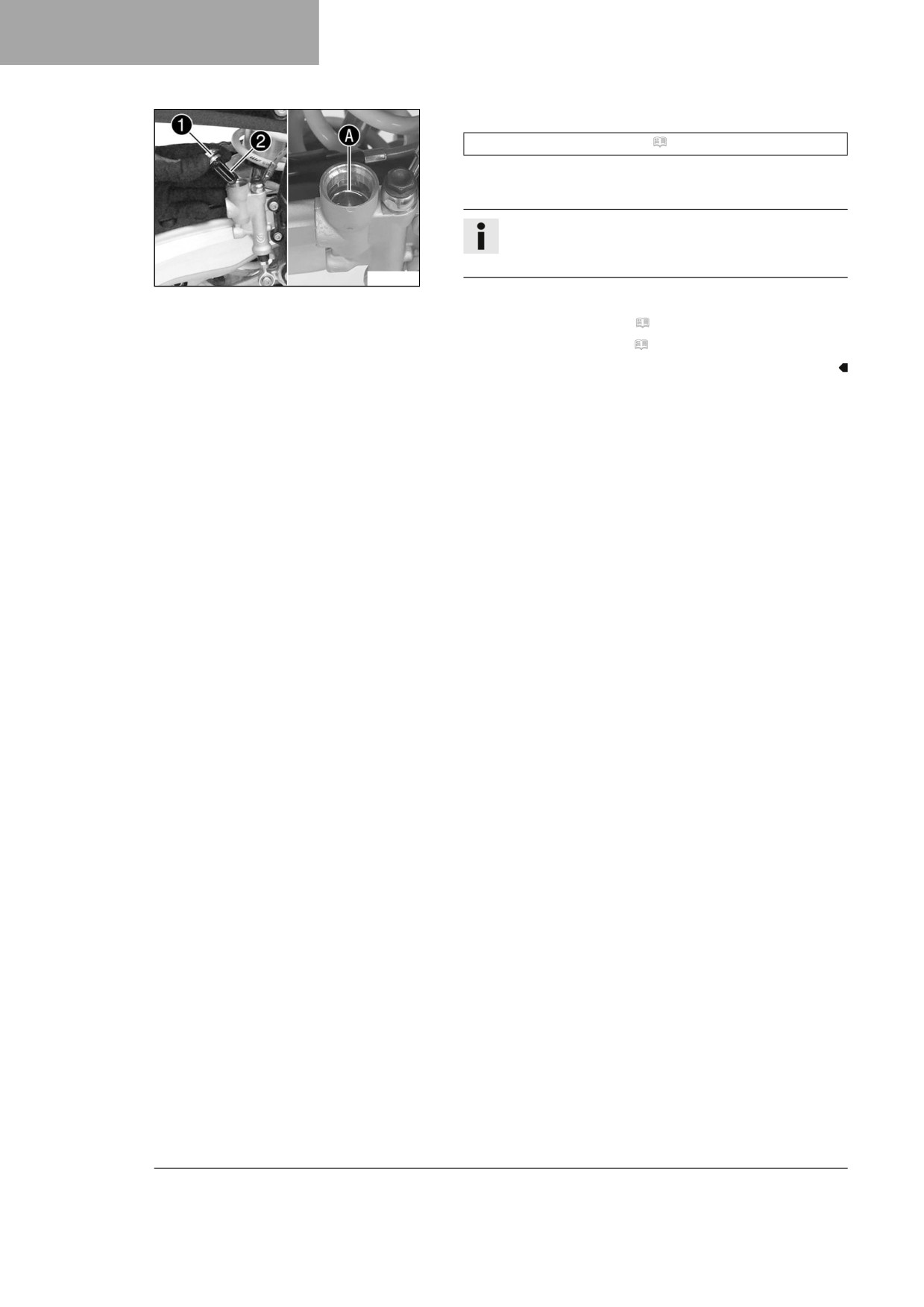
- Correct brake fluid level to marking A.
Brake fluid DOT 4 / DOT 5.1 ( p. 140)
- Mount and tighten screw cap 1 with membrane 2 and the
O-ring.
Info
Use water to immediately clean up any brake fluid that
has overflowed or spilled.
T04401-01
Finishing work
- Install the frame protector. ( p. 52)
- Install the right side panel. ( p. 67)
94
WHEELS, TIRES
13
13.1
Removing the front wheel
Preparatory work
- Raise the motorcycle with a lift stand. ( p. 49)
Main work
- Manually press the brake caliper toward the brake disc to
push back the brake pistons.
Info
Make sure that you do not press the brake caliper
against the spokes when pushing back the brake pis-
tons.
J00082-10
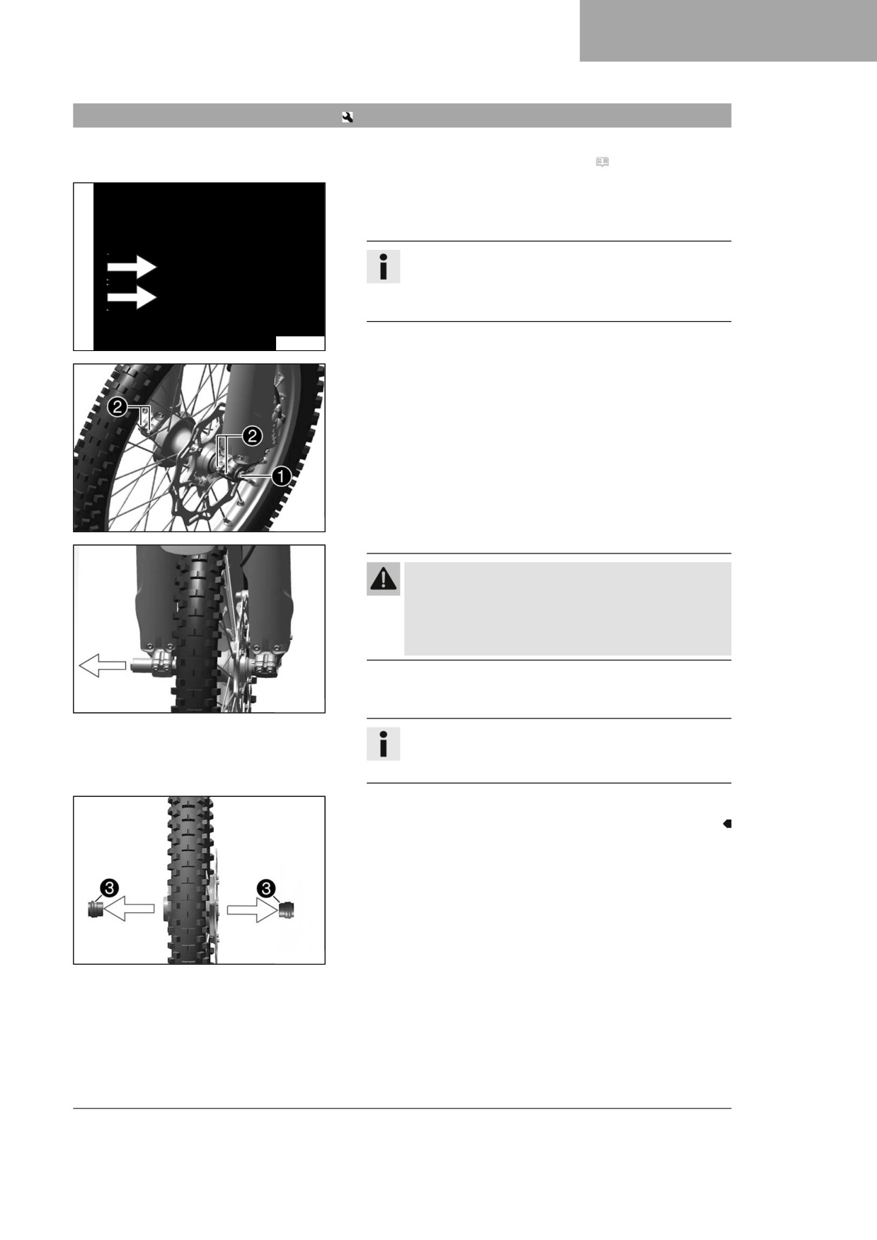
- Loosen screw 1 by several rotations.
- Loosen screws 2.
- Press on screw 1 to push the wheel spindle out of the axle
clamp.
- Remove screw 1.
A01199-10
Warning
Danger of accidents Damaged brake discs reduce
the braking effect.
- Always lay the wheel down in such a way that the
brake disc is not damaged.
- Hold front wheel and remove wheel spindle. Take the front
wheel out of the fork.
A01201-10
Info
Do not actuate the hand brake lever when the front
wheel is removed.
- Remove spacers 3.
A01188-11
95
13
WHEELS, TIRES
13.2
Installing the front wheel
Warning
Danger of accidents Oil or grease on the brake discs reduces the braking effect.
-
Always keep the brake discs free of oil and grease.
–
Clean the brake discs with brake cleaner when necessary.
-
Check the wheel bearing for damage and wear.
» If the wheel bearing is damaged or worn:
- Change front wheel bearing.
-
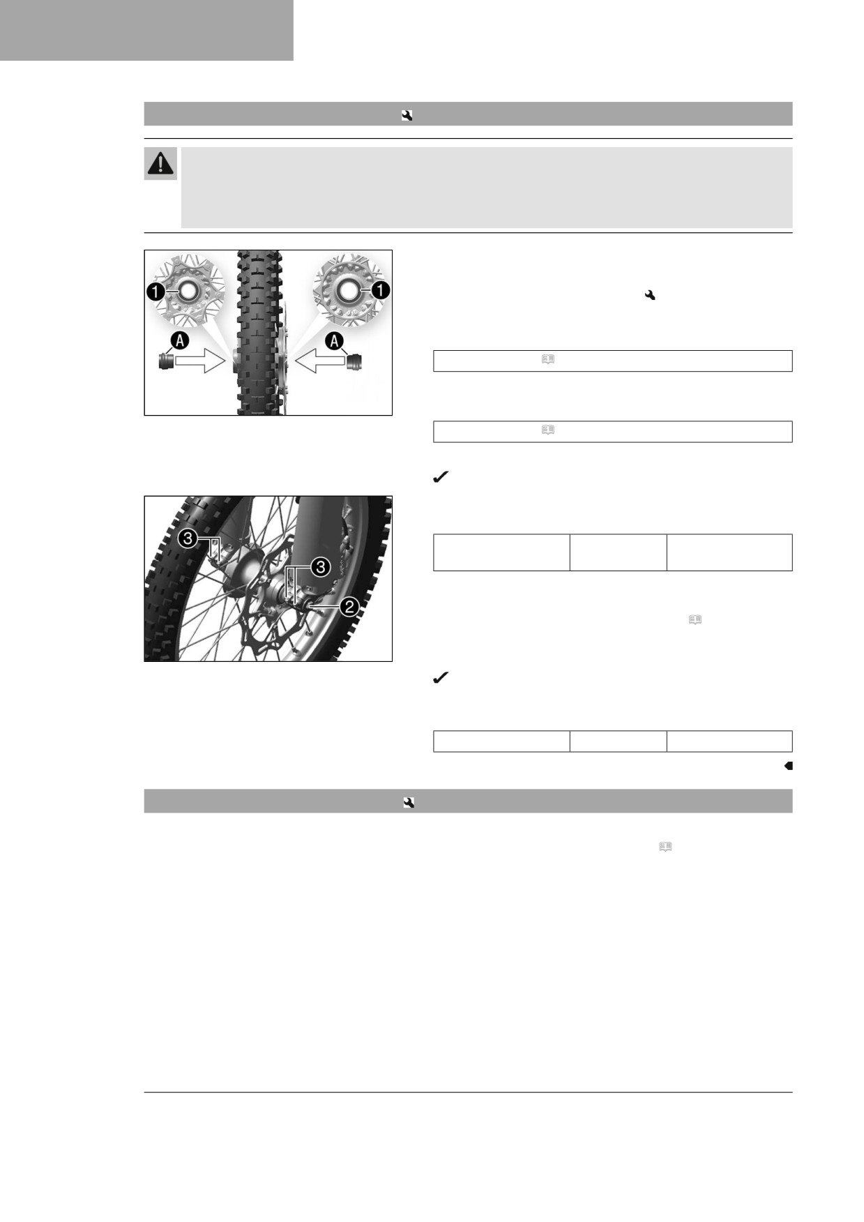
Clean and grease shaft seal rings 1 and contact
surfaces A of the spacers.
Long-life grease ( p. 142)
-
Insert the spacers.
A01188-10
-
Clean and lightly grease the wheel spindle.
Long-life grease ( p. 142)
-
Position the front wheel and insert the wheel spindle.
The brake linings are correctly positioned.
-
Mount and tighten screw 2.
Guideline
Screw, front wheel
M20x1.5
35 Nm (25.8 lbf ft)
spindle
-
Operate the hand brake lever several times until the brake
linings are seated correctly against the brake disc.
-
Remove the motorcycle from the lift stand. ( p. 49)
–
Operate the front brake and compress the fork a few times
A01199-11
firmly.
The fork legs straighten.
-
Tighten screws 3.
Guideline
Screw, fork stub
M8
15 Nm (11.1 lbf ft)
13.3
Removing the rear wheel
Preparatory work
- Raise the motorcycle with a lift stand. ( p. 49)
96
WHEELS, TIRES
13
Main work
-
Manually press the brake caliper toward the brake disc to
push back the brake piston.
Info
Make sure that you do not press the brake caliper
against the spokes when pushing back the brake pis-
ton.
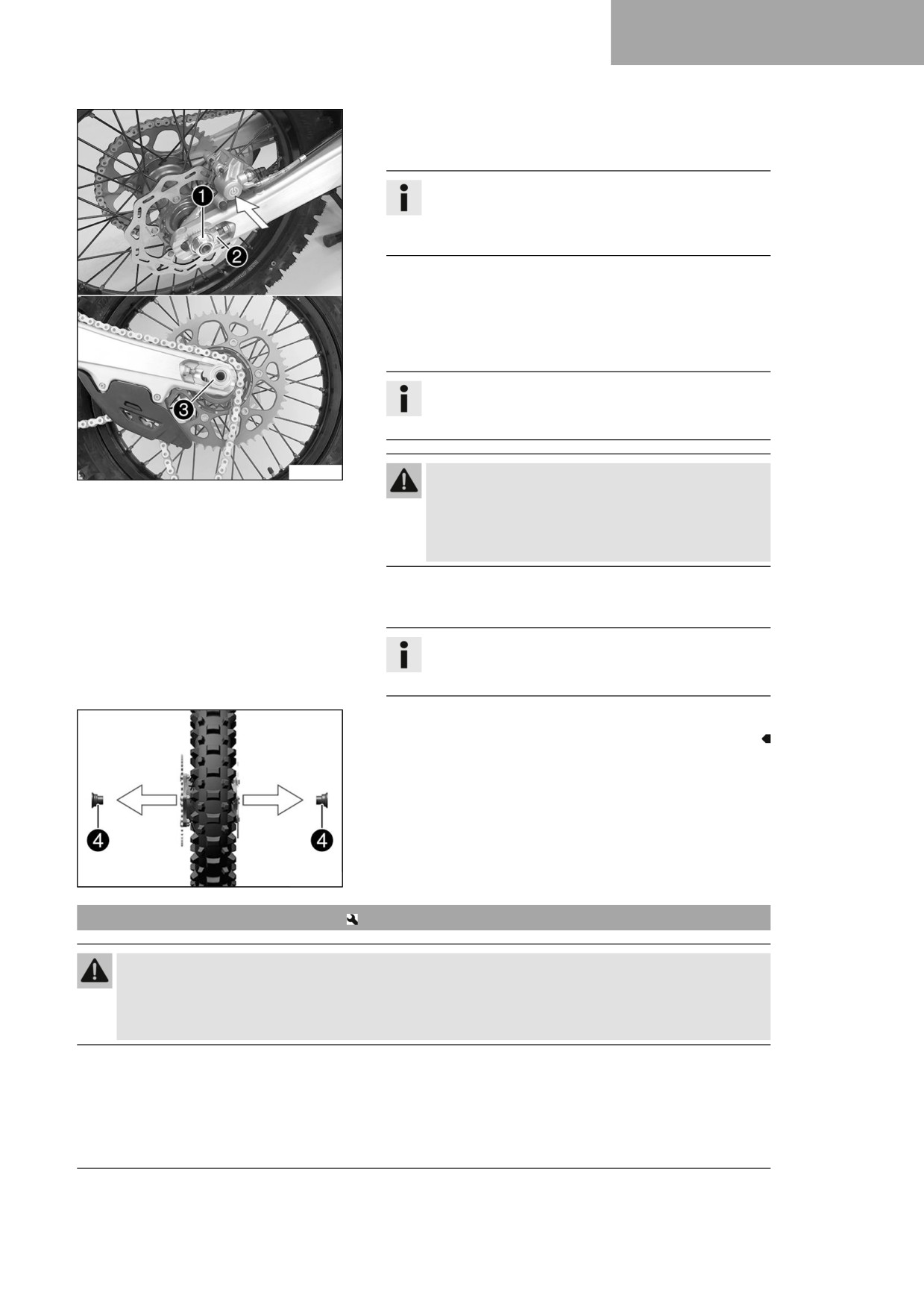
-
Remove nut 1.
–
Take off chain adjuster 2. Pull out wheel spindle 3 far
enough to allow the rear wheel to be pushed forward.
-
Push the rear wheel forward as far as possible. Remove the
chain from the rear sprocket.
Info
Cover the components to protect them against dam-
age.
H04989-10
Warning
Danger of accidents Damaged brake discs reduce
the braking effect.
- Always lay the wheel down in such a way that the
brake disc is not damaged.
-
Hold the rear wheel and remove the wheel spindle. Take the
rear wheel out of the link fork.
Info
Do not operate the foot brake lever when the rear
wheel is removed.
-
Remove spacers 4.
F03727-10
13.4
Installing the rear wheel
Warning
Danger of accidents Oil or grease on the brake discs reduces the braking effect.
- Always keep the brake discs free of oil and grease.
- Clean the brake discs with brake cleaner when necessary.
97
13
WHEELS, TIRES
Main work
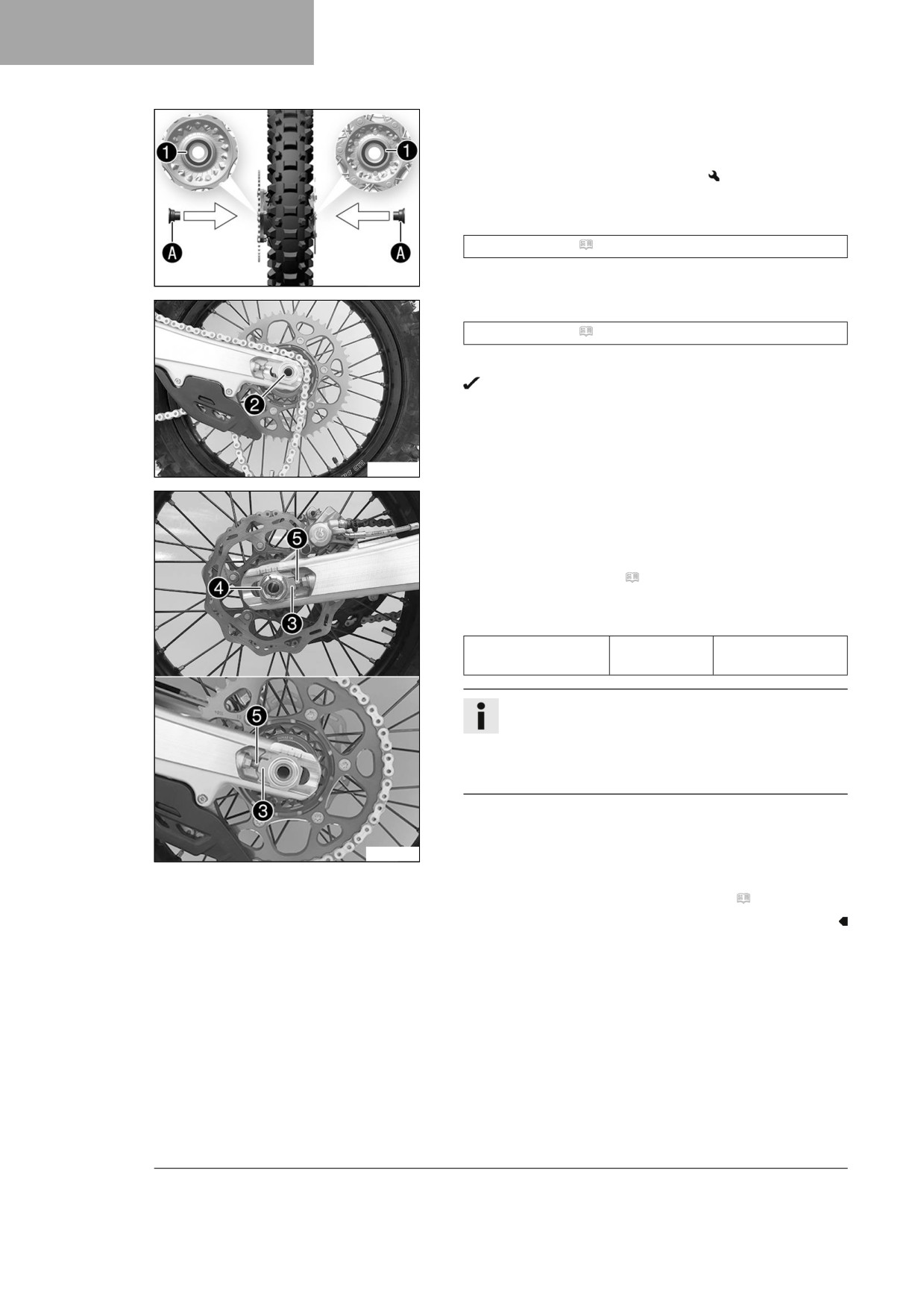
- Check the wheel bearing for damage and wear.
» If the wheel bearing is damaged or worn:
- Change the rear wheel bearing.
- Clean and grease shaft seal rings 1 and contact
surfaces A of the spacers.
Long-life grease ( p. 142)
- Insert the spacers.
F03728-10
- Clean and lightly grease the wheel spindle.
Long-life grease ( p. 142)
- Position rear wheel and insert wheel spindle 2.
The brake linings are correctly positioned.
- Mount the chain.
F03757-10
- Position chain adjuster 3. Mount nut 4, but do not tighten
it yet.
- Make sure that chain adjusters 3 are fitted correctly on
adjusting screws 5.
- Check the chain tension. ( p. 73)
- Tighten nut 4.
Guideline
Nut, wheel spindle,
M22x1.5
80 Nm (59 lbf ft)
rear
Info
The wide adjustment range of the chain adjusters
(32 mm (1.26 in)) enables different secondary ratios
with the same chain length.
Chain adjusters 3 can be turned by 180°.
- Operate the foot brake lever repeatedly until the brake lin-
ings are in contact with the brake disc and there is a pressure
point.
H04990-10
Finishing work
- Remove the motorcycle from the lift stand. ( p. 49)
98
WHEELS, TIRES
13
13.5
Checking the tire condition
Info
Only mount tires approved and/or recommended by Husqvarna Motorcycles.
Other tires could have a negative effect on handling characteristics.
The type, condition, and pressure of the tires all have a major impact on the handling characteristic of
the motorcycle.
The tires mounted on the front and rear wheels must have a similar profile.
Worn tires have a negative effect on handling characteristics, especially on wet surfaces.
Preparatory work
- Raise the motorcycle with a lift stand. ( p. 49)
Main work
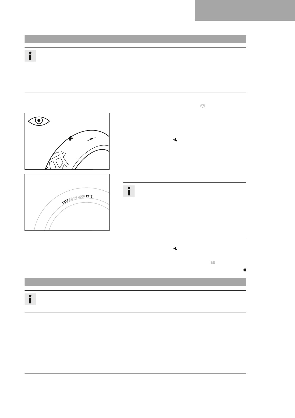
- Check the front and rear tires for cuts, embedded objects,
and other damage.
» If the tires have cuts, run-in objects, or other damage:
- Change the tires.
400602-10
- Check the tire age.
Info
The tire date of manufacture is usually contained in
the tire label and is indicated by the last four digits
of the DOT number. The first two digits indicate the
week of manufacture and the last two digits the year
of manufacture.
Husqvarna Motorcycles recommends that the tires be
changed after 5 years at the latest, regardless of the
H01144-01
actual wear.
» If the tires are more than five years old:
- Change the tires.
Finishing work
- Remove the motorcycle from the lift stand. ( p. 49)
13.6
Checking tire pressure
Info
Low tire pressure leads to abnormal wear and overheating of the tire.
Correct tire pressure ensures optimal riding comfort and maximum tire service life.
99
13
WHEELS, TIRES
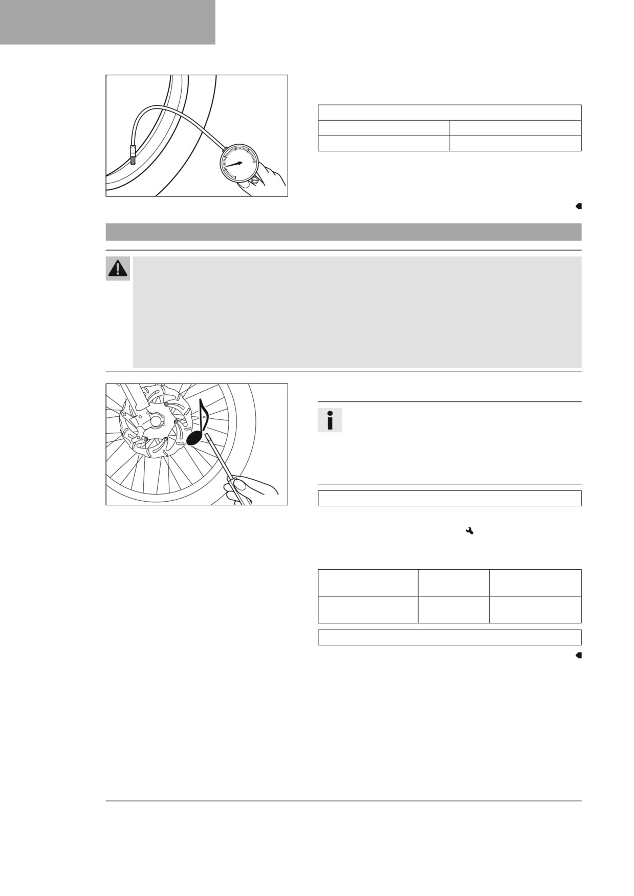
- Remove protection cap.
- Check tire pressure when the tires are cold.
Offroad tire pressure
front
1.0 bar (15 psi)
rear
1.0 bar (15 psi)
» If the tire pressure does not meet specifications:
- Correct tire pressure.
400695-01
- Mount the protection cap.
13.7
Checking the spoke tension
Warning
Danger of accidents Incorrectly tensioned spokes impair the handling characteristic and result in
secondary damage.
The spokes break due to being overloaded if they are too tightly tensioned. If the tension in the spokes
is too low, then lateral and radial run-out will form in the wheel. Other spokes will become looser as a
result.
- Check spoke tension regularly, and in particular on a new vehicle. (Your authorized
Husqvarna Motorcycles workshop will be glad to help.)
- Strike each spoke briefly using a screwdriver blade.
Info
The frequency of the sound depends on the spoke
length and spoke diameter.
If spokes of the same length and diameter vibrate with
a different tone, this is an indication that the spoke
tensions differ.
400694-01
You should hear a high note.
» If the spoke tension differs:
- Correct the spoke tension.
- Check the spoke torque.
Guideline
Spoke nipple, front
M4.5
6 Nm (4.4 lbf ft)
wheel
Spoke nipple, rear
M4.5
6 Nm (4.4 lbf ft)
wheel
Torque wrench kit (58429094000)
100
ELECTRICAL SYSTEM
14
14.1
Removing the 12-V battery
Caution
Danger of burns The voltage regulator gets very hot when the vehicle is operated.
- Allow the voltage regulator to cool down before performing any work.
Note
Environmental hazard
12 V batteries contain environmentally hazardous materials.
– Do not dispose of 12 V batteries as household waste.
- Dispose of 12 V batteries at a collection point for used batteries.
Preparatory work
- Remove the seat. ( p. 62)
Main work
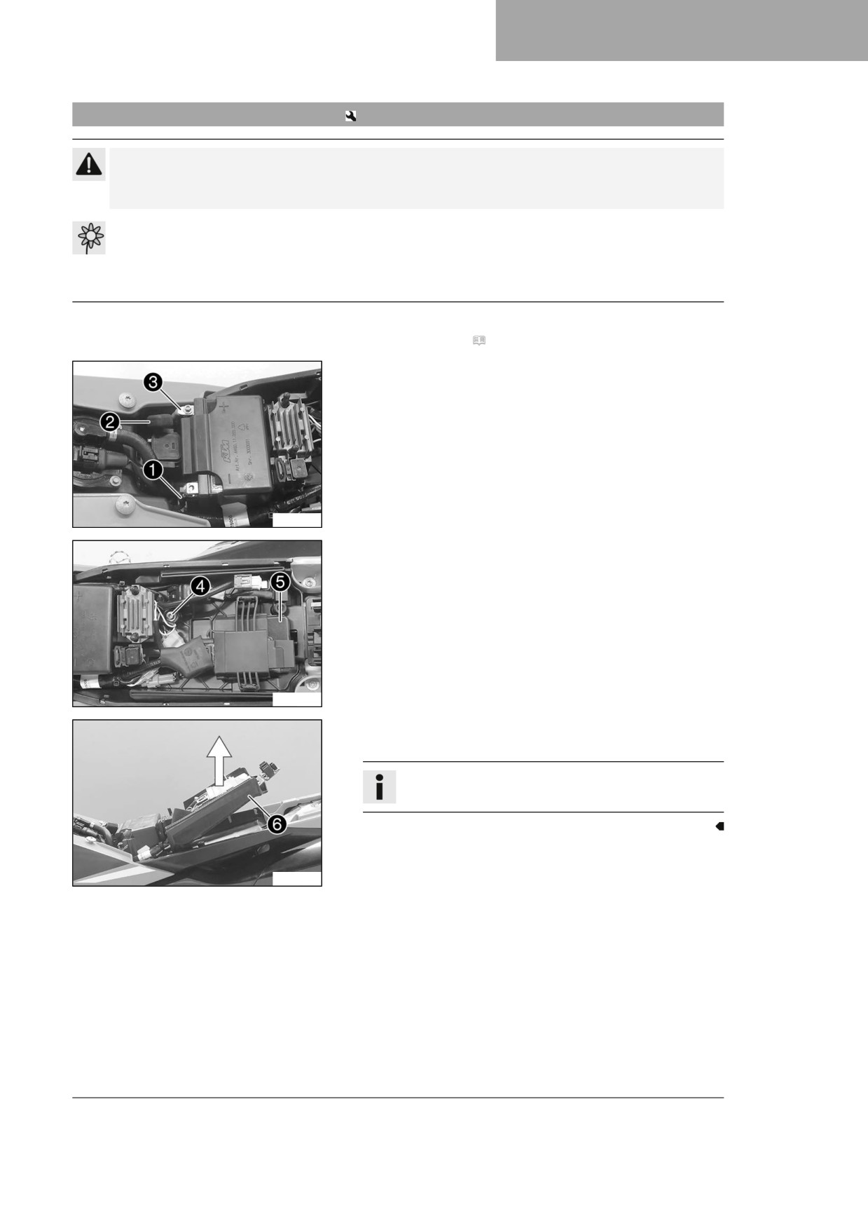
- Disconnect negative cable 1 from the 12-V battery.
- Pull back positive terminal cover 2 and disconnect positive
cable 3 from the 12-V battery.
F03729-10
- Remove screw 4.
- Pull off engine control unit 5 from the holder and hang to
the side.
F03730-10
- Pull up battery holding bracket 6 and remove the 12-V bat-
tery to the rear.
Info
Pay attention to the wiring harness.
F03731-10
101
14
ELECTRICAL SYSTEM
14.2
Installing the 12-V battery
Main work
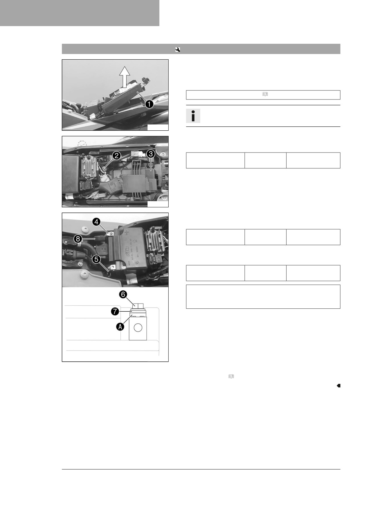
- Pull up battery holding bracket 1, insert the 12-V battery
into the battery compartment with the terminals facing
upward and secure with battery holding bracket 1.
12 V battery (HJTZ5S-FP-C) ( p. 134)
Info
Ensure that the cable is routed correctly.
F03731-11
- Mount and tighten screw 2.
Guideline
Remaining screws,
M6
10 Nm (7.4 lbf ft)
chassis
- Attach the engine control unit 3 to the holder.
F03730-11
- Connect positive cable 4 to the 12-V battery.
Guideline
Screw, battery termi-
M5
2.5 Nm (1.84 lbf ft)
nal
- Connect negative cable 5 to the 12 V battery.
Guideline
Screw, battery termi-
M5
2.5 Nm (1.84 lbf ft)
nal
Contact disks A must be mounted under screws 6 and
cable sockets 7 with the claws toward the battery termi-
nal.
- Slide positive terminal cover 8 over the positive terminal.
F03732-10
Finishing work
- Mount the seat. ( p. 62)
102
ELECTRICAL SYSTEM
14
14.3
Charging the 12-V battery
Warning
Risk of injury
12 V batteries contain harmful substances.
– Keep 12 V batteries out of the reach of children.
- Keep sparks and open flames away from 12 V batteries.
- Only charge 12 V batteries in well-ventilated rooms.
- Maintain a minimum clearance from inflammable materials when charging 12 V batteries.
Minimum clearance
1 m (3 ft)
– Do not charge deeply discharged 12 V batteries if the charge is already below the minimum voltage.
Minimum voltage before the start of the charge
9V
– Dispose of 12 V batteries correctly if they have less than the minimum voltage.
Note
Environmental hazard
12 V batteries contain environmentally hazardous materials.
– Do not dispose of 12 V batteries as household waste.
- Dispose of 12 V batteries at a collection point for used batteries.
Info
Even when there is no load on the 12-V battery, it discharges steadily each day.
The charging level and the method of charging are very important for the service life of the 12-V battery.
Rapid recharging with a high charging current shortens the service life of the battery.
If the charging current, charging voltage, or charging time is exceeded, the 12 V battery will be
destroyed.
If the 12-V battery is discharged by repeated starting, charge the 12-V battery immediately.
If the 12-V battery is left in a discharged state for an extended period, it will become deeply discharged
and suffer a loss of capacity, destroying the battery.
The 12-V battery is maintenance-free.
Preparatory work
- Remove the seat. ( p. 62)
- Remove the 12-V battery.
(
p. 101)
Main work
- Check the battery voltage.
» Battery voltage: < 9 V
- Do not charge the 12-V battery.
- Replace the 12-V battery and dispose of the old 12-V
battery properly.
» If the specifications have been met:
Battery voltage: ≥ 9 V
F01568-10
- Connect a battery charger to the 12-V battery. Switch
on the battery charger.
103
14
ELECTRICAL SYSTEM
Guideline
The charging current, charging voltage, and charg-
ing time must not be exceeded.
Maximum charging volt-
14.4 V
age
Maximum charging cur-
3.0 A
rent
Maximum charging time
24 h
Recharge the 12-V bat-
6 months
tery regularly when the
motorcycle is not being
used
(EU) battery charger (26529974000)
Alternative 1
(US) battery charger (26529974500)
These battery chargers test whether the 12-V bat-
tery retains its voltage. It is also impossible to over-
charge the 12-V battery with these battery chargers.
The charging time may be longer at low temperatures.
These battery chargers are only suitable for lithium
iron phosphate batteries. Read the accompanying
instructions for Husqvarna Motorcycles accessories.
Info
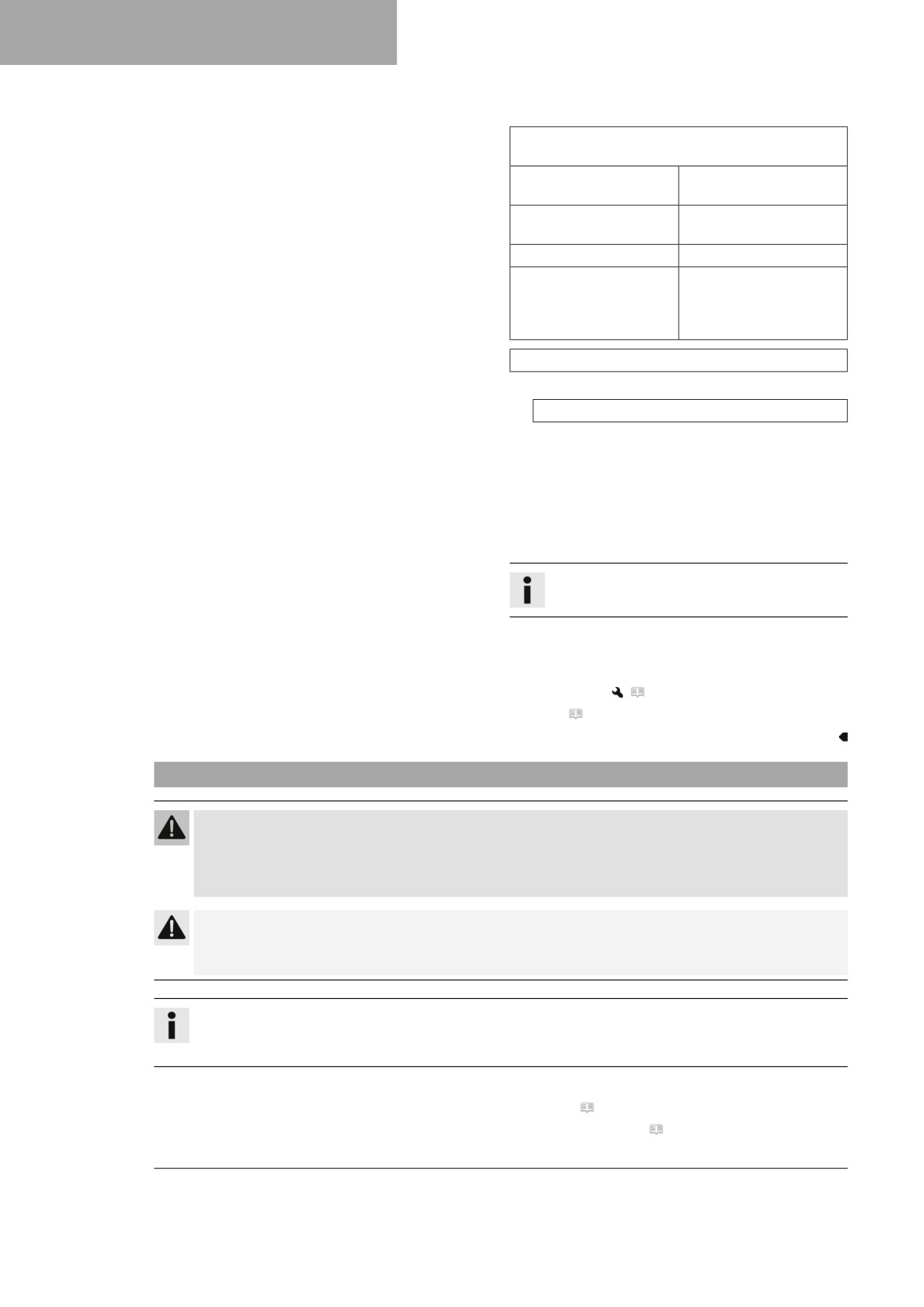
Never remove cover 1.
-
Switch off the battery charger after charging and disconnect
from the 12-V battery.
Finishing work
- Install the 12-V battery.
(
p. 102)
– Mount the seat. ( p. 62)
14.4
Changing the main fuse
Warning
Fire hazard Incorrect fuses overload the electrical system.
- Only use fuses with the required ampere value.
- Do not bypass or repair fuses.
Caution
Danger of burns The voltage regulator gets very hot when the vehicle is operated.
- Allow the voltage regulator to cool down before performing any work.
Info
The main fuse protects all electrical power consumers of the vehicle. It is located in the starter relay
housing under the seat.
Preparatory work
- Remove the seat. ( p. 62)
- Remove the right side panel. ( p. 67)
104
ELECTRICAL SYSTEM
14
– Remove the fuel tank.
(
p. 69)
Main work
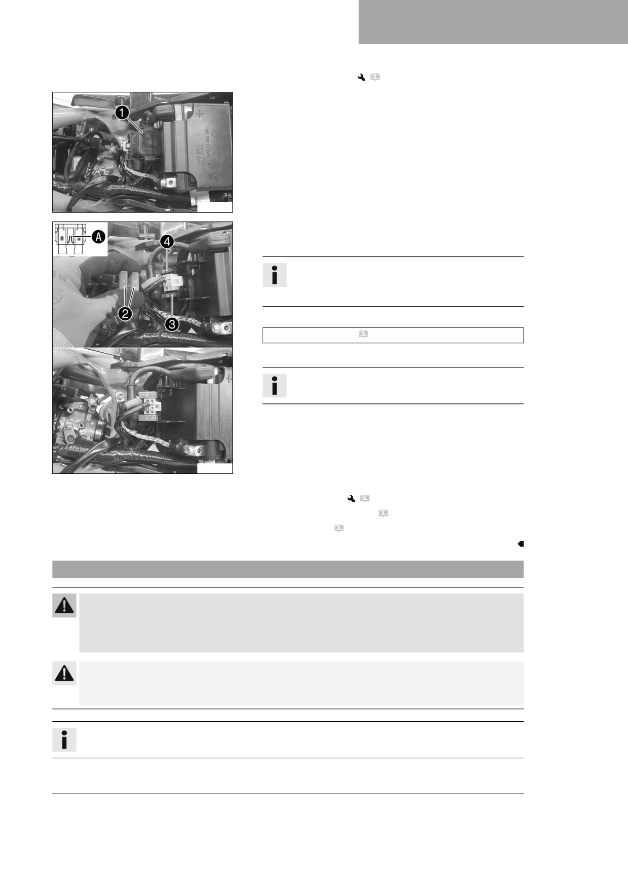
- Pull starter relay 1 from the holder.
F03751-10
- Take off protection caps 2.
- Remove faulty main fuse 3.
Info
A faulty fuse has a burned-out fuse wire A.
A spare fuse 4 is located in the starter relay.
- Insert a new main fuse.
Fuse (58011109110) ( p. 134)
- Check that the electrical system is functioning properly.
Tip
Insert a spare fuse so that it is available if needed.
- Mount the protection caps.
- Mount the starter relay onto the holder and route the cable.
F03752-10
Finishing work
- Install the fuel tank.
(
p. 71)
– Install the right side panel. ( p. 67)
- Mount the seat. ( p. 62)
14.5
Changing the fuse of the fuel pump
Warning
Fire hazard Incorrect fuses overload the electrical system.
- Only use fuses with the required ampere value.
- Do not bypass or repair fuses.
Caution
Danger of burns The voltage regulator gets very hot when the vehicle is operated.
- Allow the voltage regulator to cool down before performing any work.
Info
The fuel pump is protected by the fuel pump fuse. This is located under the seat.
105
14
ELECTRICAL SYSTEM
Preparatory work
- Remove the seat. ( p. 62)
Main work
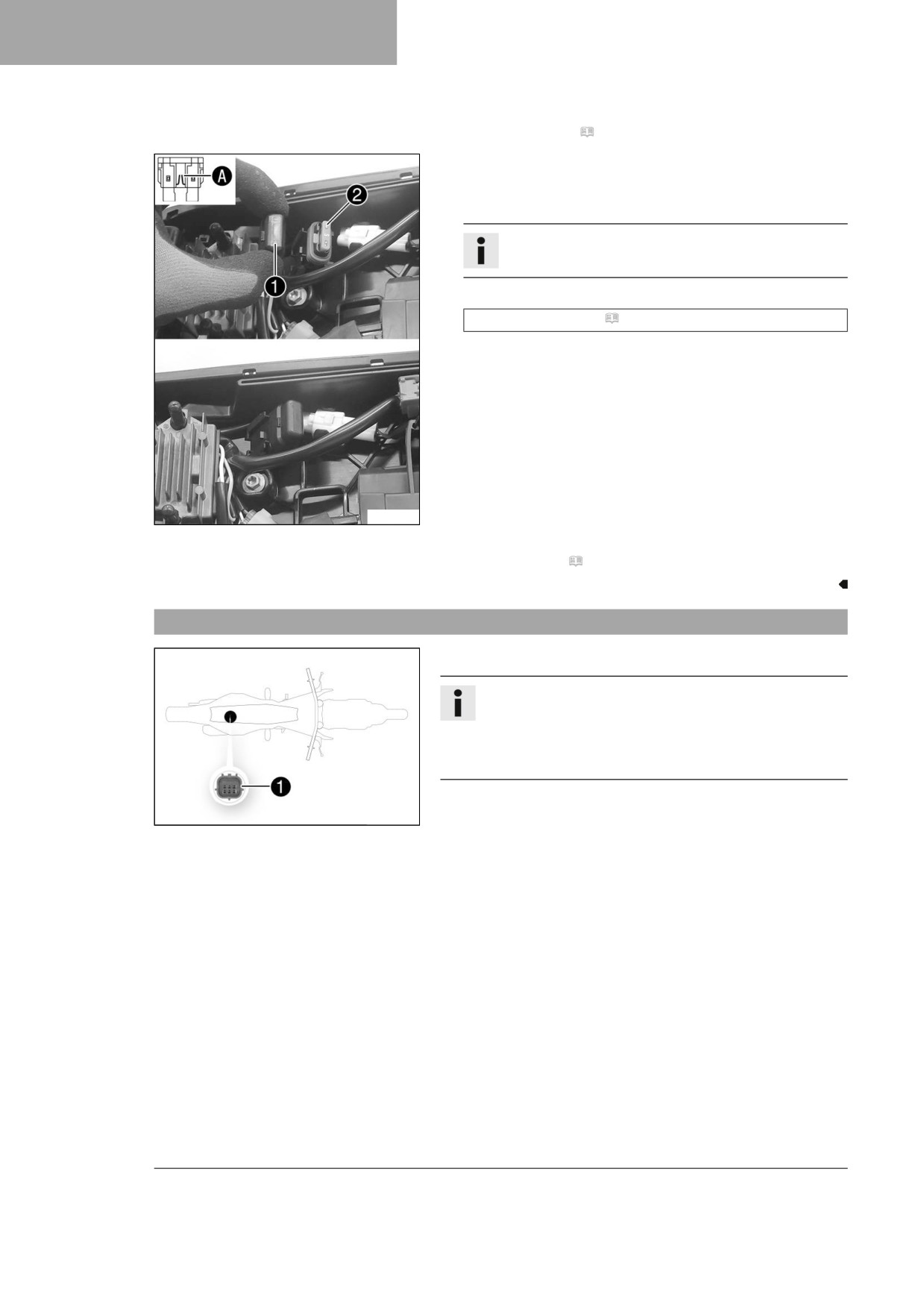
- Take off protection cap 1.
- Remove the faulty fuse 2.
Info
A faulty fuse has a burned-out fuse wire A.
- Insert the new fuse for the fuel pump.
Fuse (58011109105) ( p. 134)
- Check that the electrical system is functioning properly.
- Attach the protection cap.
F03753-10
Finishing work
- Mount the seat. ( p. 62)
14.6
Diagnostics connector
Diagnostics connector 1 is located under the seat.
Info
As soon as the diagnostics tool is connected, the service
hour counter starts running.
Before longer diagnostic sessions, unplug the service
hour counter behind the start number plate.
A01108-10
106
COOLING SYSTEM
15
15.1
Cooling system
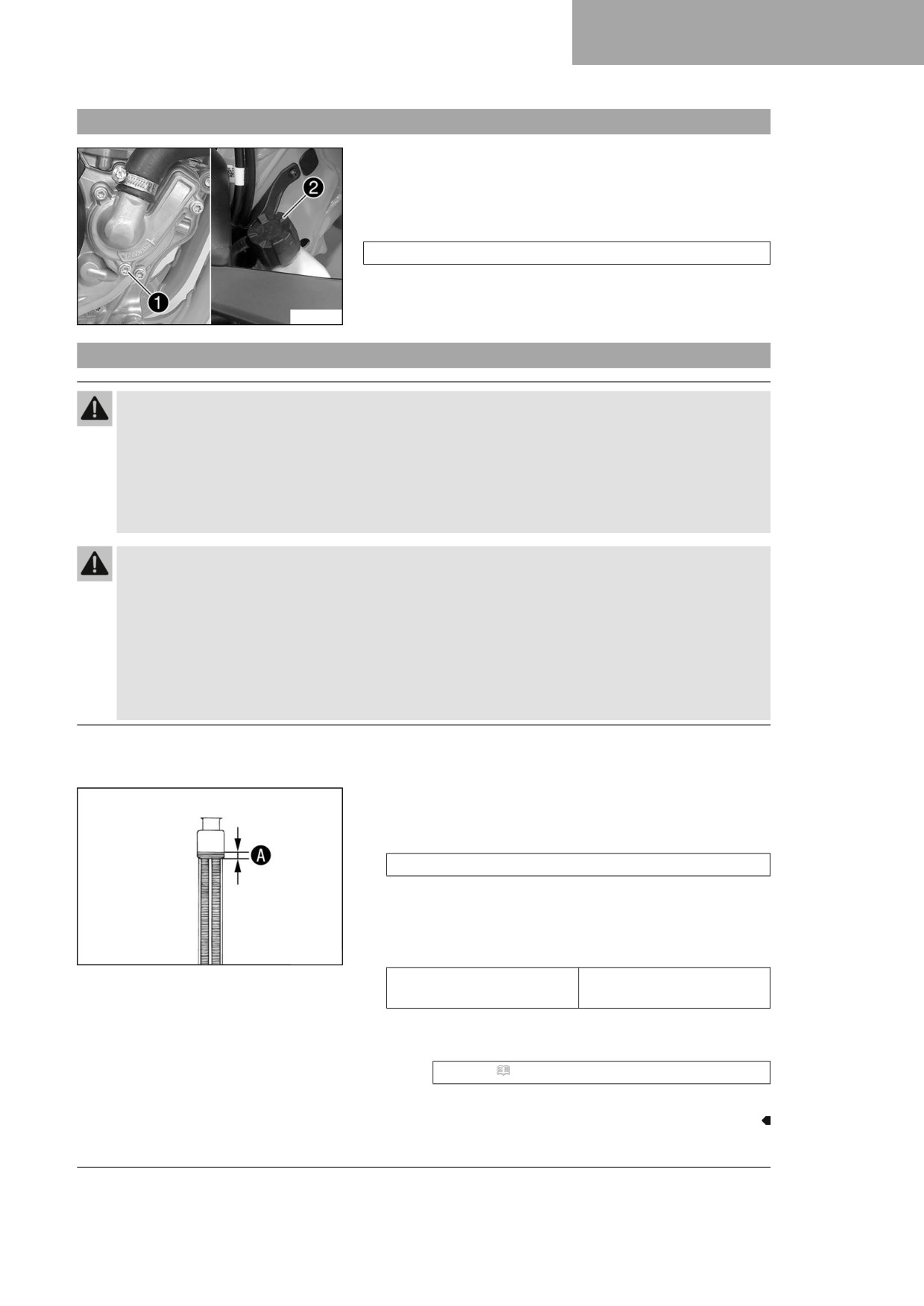
Water pump 1 in the engine circulates the coolant.
The pressure resulting from the warming of the cooling system is
regulated by a valve in radiator cap 2. This ensures that operat-
ing the vehicle at the specified coolant temperature will not result
in a risk of malfunctions.
120 °C (248 °F)
Cooling is effected by the air stream.
The lower the speed, the less the cooling effect. Dirty cooling fins
F03740-10
also reduce the cooling effect.
15.2
Checking the antifreeze and coolant level
Warning
Danger of scalding During motorcycle operation, the coolant gets hot and is under pressure.
- Do not open the radiator, the radiator hoses or other cooling system components if the engine or
the cooling system are at operating temperature.
- Allow the cooling system and the engine to cool down before you open the radiator, the radiator
hoses or other components of the cooling system.
- In the event of scalding, rinse the area affected immediately with lukewarm water.
Warning
Danger of poisoning Coolant is harmful to health.
-
Keep coolant out of the reach of children.
–
Do not allow coolant to come into contact with the skin, the eyes and clothing.
–
Consult a doctor immediately if coolant is swallowed.
–
Rinse the affected area immediately with plenty of water in the event of contact with the skin.
–
Rinse eyes thoroughly with water and consult a doctor immediately if coolant gets into the eyes.
–
Change clothing if coolant spills onto your clothing.
Condition
The engine is cold.
- Stand the motorcycle upright on a horizontal surface.
- Remove the radiator cap.
- Check the antifreeze in the coolant.
−25 … −45 °C (−13 … −49 °F)
» If the antifreeze in the coolant does not match the speci-
fied value:
- Correct the antifreeze in the coolant.
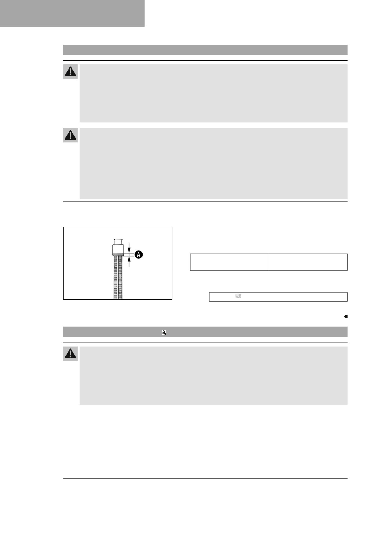
- Check the coolant level in the radiator.
400243-10
10 mm (0.39 in)
Coolant level A above the
radiator fins
» If the coolant level does not match the specified value:
- Correct the coolant level.
Coolant ( p. 140)
- Mount the radiator cap.
107
15
COOLING SYSTEM
15.3
Checking the coolant level
Warning
Danger of scalding During motorcycle operation, the coolant gets hot and is under pressure.
- Do not open the radiator, the radiator hoses or other cooling system components if the engine or
the cooling system are at operating temperature.
- Allow the cooling system and the engine to cool down before you open the radiator, the radiator
hoses or other components of the cooling system.
- In the event of scalding, rinse the area affected immediately with lukewarm water.
Warning
Danger of poisoning Coolant is harmful to health.
- Keep coolant out of the reach of children.
- Do not allow coolant to come into contact with the skin, the eyes and clothing.
- Consult a doctor immediately if coolant is swallowed.
- Rinse the affected area immediately with plenty of water in the event of contact with the skin.
- Rinse eyes thoroughly with water and consult a doctor immediately if coolant gets into the eyes.
- Change clothing if coolant spills onto your clothing.
Condition
The engine is cold.
- Stand the motorcycle upright on a horizontal surface.
- Remove the radiator cap.
- Check the coolant level in the radiator.
10 mm (0.39 in)
Coolant level A above the
radiator fins
» If the coolant level does not match the specified value:
- Correct the coolant level.
400243-10
Coolant ( p. 140)
- Mount the radiator cap.
15.4
Draining the coolant
Warning
Danger of scalding During motorcycle operation, the coolant gets hot and is under pressure.
- Do not open the radiator, the radiator hoses or other cooling system components if the engine or
the cooling system are at operating temperature.
- Allow the cooling system and the engine to cool down before you open the radiator, the radiator
hoses or other components of the cooling system.
- In the event of scalding, rinse the area affected immediately with lukewarm water.
108
COOLING SYSTEM
15
Warning
Danger of poisoning Coolant is harmful to health.
- Keep coolant out of the reach of children.
- Do not allow coolant to come into contact with the skin, the eyes and clothing.
- Consult a doctor immediately if coolant is swallowed.
- Rinse the affected area immediately with plenty of water in the event of contact with the skin.
- Rinse eyes thoroughly with water and consult a doctor immediately if coolant gets into the eyes.
- Change clothing if coolant spills onto your clothing.
Condition
The engine is cold.
- Position the motorcycle upright.
- Place an appropriate container under the water pump cover.
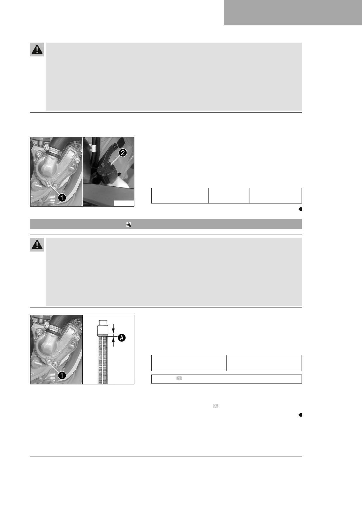
- Remove screw 1. Take off radiator cap 2.
- Completely drain the coolant.
- Mount and tighten screw 1 with a new seal ring.
Guideline
Screw, water pump
M6x25
10 Nm (7.4 lbf ft)
cover
F03740-10
15.5
Refilling with coolant
Warning
Danger of poisoning Coolant is harmful to health.
- Keep coolant out of the reach of children.
- Do not allow coolant to come into contact with the skin, the eyes and clothing.
- Consult a doctor immediately if coolant is swallowed.
- Rinse the affected area immediately with plenty of water in the event of contact with the skin.
- Rinse eyes thoroughly with water and consult a doctor immediately if coolant gets into the eyes.
- Change clothing if coolant spills onto your clothing.
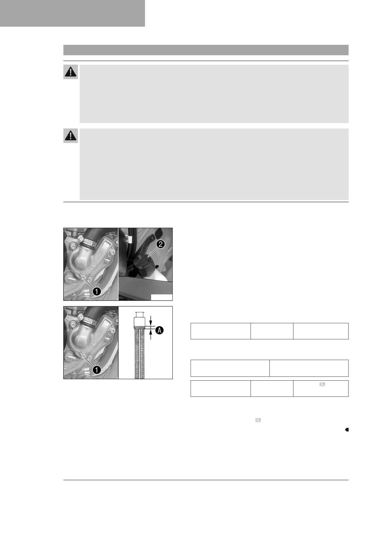
- Make sure that screw 1 is tightened.
- Position the motorcycle upright.
- Pour coolant in up to measurement A above the radiator
fins.
Guideline
10 mm (0.39 in)
Distance A above the radi-
ator fins
Coolant ( p. 140)
F03741-10
- Mount the radiator cap.
- Go for a short test ride.
- Check the coolant level. ( p. 108)
109
15
COOLING SYSTEM
15.6
Changing the coolant
Warning
Danger of scalding During motorcycle operation, the coolant gets hot and is under pressure.
- Do not open the radiator, the radiator hoses or other cooling system components if the engine or
the cooling system are at operating temperature.
- Allow the cooling system and the engine to cool down before you open the radiator, the radiator
hoses or other components of the cooling system.
- In the event of scalding, rinse the area affected immediately with lukewarm water.
Warning
Danger of poisoning Coolant is harmful to health.
- Keep coolant out of the reach of children.
- Do not allow coolant to come into contact with the skin, the eyes and clothing.
- Consult a doctor immediately if coolant is swallowed.
- Rinse the affected area immediately with plenty of water in the event of contact with the skin.
- Rinse eyes thoroughly with water and consult a doctor immediately if coolant gets into the eyes.
- Change clothing if coolant spills onto your clothing.
Condition
The engine is cold.
- Position the motorcycle upright.
- Place an appropriate container under the water pump cover.
- Remove screw 1. Take off radiator cap 2.
- Completely drain the coolant.
F03740-10
- Mount and tighten screw 1 with a new seal ring.
Guideline
Screw, water pump
M6
10 Nm (7.4 lbf ft)
cover
- Pour coolant in up to level A above the radiator fins.
Guideline
10 mm (0.39 in)
Distance A above the radi-
ator fins
F03741-10
Coolant
0.90 l
Coolant ( p. 140)
(0.95 qt.)
- Mount the radiator cap.
- Go for a short test ride.
- Check the coolant level. ( p. 108)
110
TUNING THE ENGINE
16
16.1
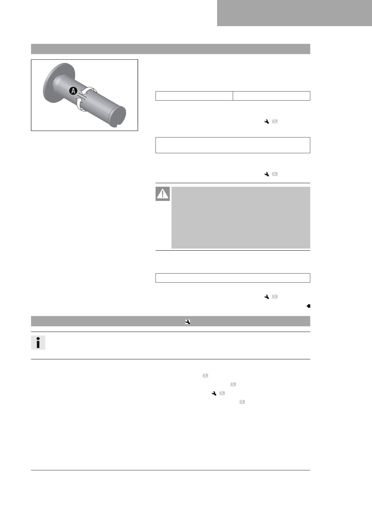
Checking the play in the throttle cable
-
Check the throttle grip for smooth operation.
–
Move the handlebar to the straight-ahead position. Turn the
throttle grip back and forth slightly and determine the play in
throttle cable A.
Play in throttle cable
3 … 5 mm (0.12 … 0.2 in)
» If the throttle cable play does not meet the specified
value:
- Adjust the play in the throttle cable.
(
p. 111)
400192-11
-
Push the cold start button in all the way.
When the throttle grip is turned forward, the cold start but-
ton returns to its original position.
» If the cold start button does not return to its original posi-
tion:
- Adjust the play in the throttle cable.
(
p. 111)
Danger
Danger of poisoning Exhaust gases are toxic and
inhaling them may result in unconsciousness and
death.
- Always make sure there is sufficient ventilation
when running the engine.
- Use effective exhaust extraction when starting or
running the engine in an enclosed space.
-
Start the engine and let it run at idle speed. Move the handle-
bar to and fro over the entire steering range.
The idle speed must not change.
» If the idle speed changes:
- Adjust the play in the throttle cable.
(
p. 111)
16.2
Adjusting the play in the throttle cable
Info
If the correct routing of the throttle cables has already been secured, the fuel tank does not need to be
removed.
Preparatory work
- Remove the seat. ( p. 62)
- Remove the right side panel. ( p. 67)
- Remove the fuel tank.
(
p. 69)
– Check the throttle cable routing. ( p. 77)
111
16
TUNING THE ENGINE
Main work
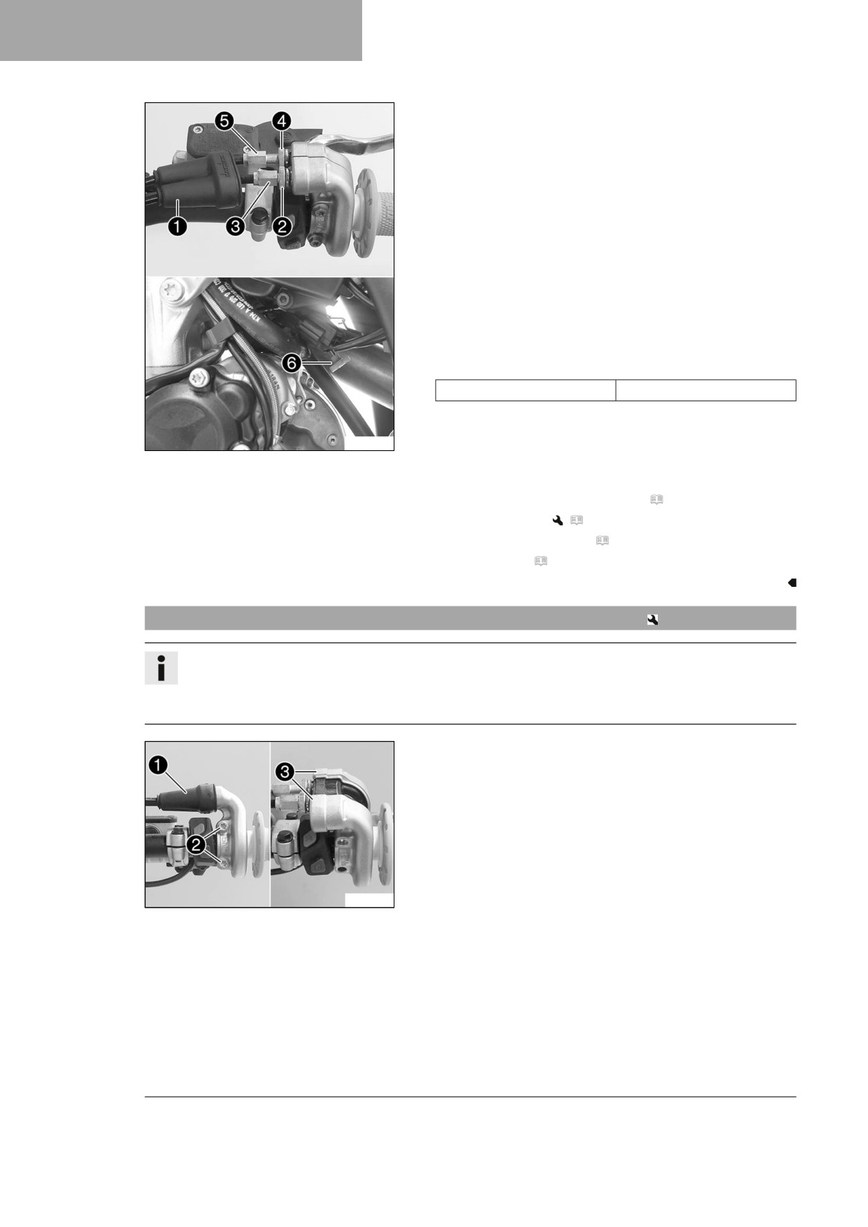
- Move the handlebar to the straight-ahead position.
- Push back sleeve 1.
- Loosen nut 2.
- Turn adjusting screw 3 in as far as possible.
- Loosen nut 4.
- Push cold start button 6 all the way to the stop.
- Turn adjusting screw 5 so that the cold start button moves
to the basic position when the throttle grip is turned to the
front.
- Tighten nut 4.
- Turn adjusting screw 3 so that there is play in the throttle
cable at the throttle grip.
Guideline
Play in throttle cable
3 … 5 mm (0.12 … 0.2 in)
– Tighten nut 2.
A01080-10
- Slide on sleeve 1.
- Check the throttle grip for smooth operation.
Finishing work
- Check the play in the throttle cable. ( p. 111)
- Install the fuel tank.
(
p. 71)
– Install the right side panel. ( p. 67)
- Mount the seat. ( p. 62)
16.3
Adjusting the characteristic map of the throttle response
Info
On the throttle grip, the characteristic map of the throttle response is changed by changing the guide
plate.
A guide plate with a different characteristic map is supplied.
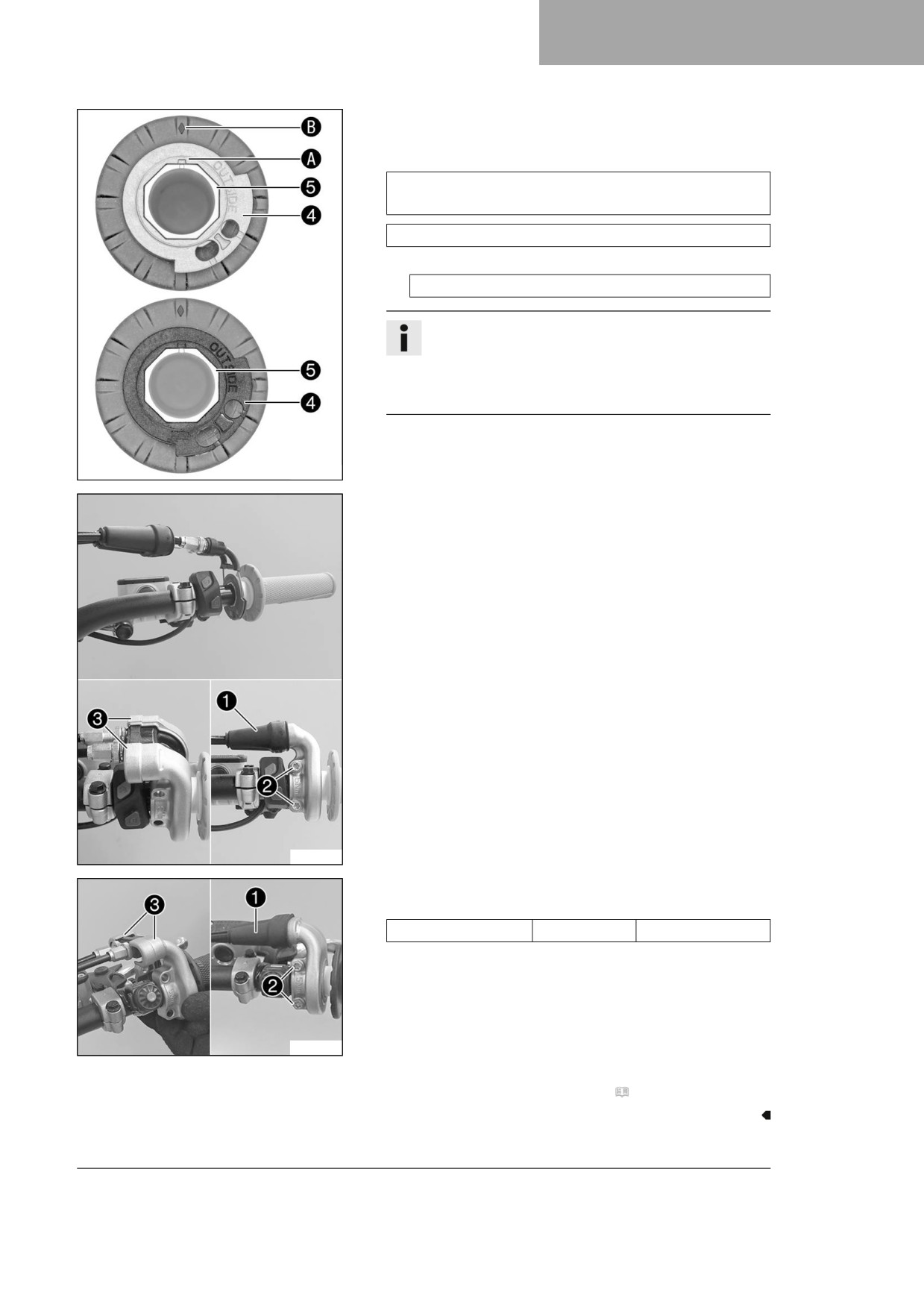
Main work
- Push back sleeve 1.
- Remove screws 2 and half-shells 3.
- Detach the throttle cables and take off the grip tube.
F03743-10
112
TUNING THE ENGINE
16
– Remove guide plate 4 from handle tube 5.
- Position the required guide plate on the grip tube.
Guideline
The label OUTSIDE must be visible. Marking A must be
positioned at marking B.
Black guide plate (A46002014000)
Alternative 1
Grey guide plate (A48002014000)
Info
The gray guide plate opens the throttle valve more
slowly.
The black guide plate opens the throttle valve more
quickly.
F03780-10
- Clean the outside of the handlebar and the inside of the grip
tube. Mount the grip tube on the handlebar.
- Attach the throttle cables to the guide plate and route cor-
rectly.
F03744-10
- Position half-shells 3, mount and tighten screws 2.
Guideline
Screw, throttle grip
M6
5 Nm (3.7 lbf ft)
– Slide on sleeve 1 and check the throttle grip for ease of
movement.
V01537-10
Finishing work
- Check the play in the throttle cable. ( p. 111)
113
16
TUNING THE ENGINE
16.4
Changing the mapping
Info
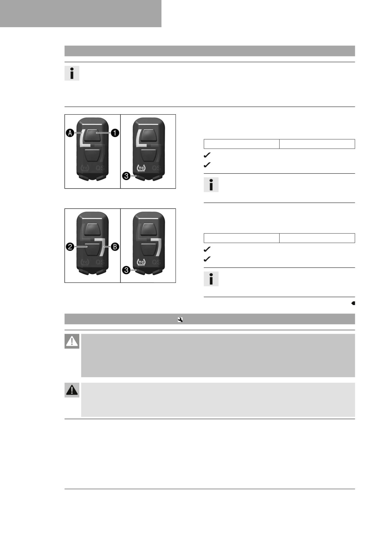
The desired engine characteristic can be activated using the combination switch.
The setting most recently selected is activated again when restarting.
Traction control can also be activated in each mapping.
The mapping can also be changed during the ride.
Activating STANDARD mapping:
- Press button 1.
Guideline
Engine speed
< 4,000 rpm
The indicator lamp A lights up.
STANDARD - balanced response
Info
F03762-10
Traction control can be activated additionally
using the TC button 3.
Activating ADVANCED mapping:
- Press button 2.
Guideline
Engine speed
< 4,000 rpm
The indicator lamp B lights up.
ADVANCED - direct response
Info
F03763-10
Traction control can be activated additionally
using the TC button 3.
16.5
Adjusting the idle speed
Danger
Danger of poisoning Exhaust gases are toxic and inhaling them may result in unconsciousness and
death.
- Always make sure there is sufficient ventilation when running the engine.
- Use effective exhaust extraction when starting or running the engine in an enclosed space.
Warning
Danger of accidents The engine may go out spontaneously if the idle speed is set too low.
- Set the idle speed to the specified value. (Your authorized Husqvarna Motorcycles workshop will be
glad to help.)
114
TUNING THE ENGINE
16
– Run the engine until warm.
The cold start button is deactivated - The cold start but-
ton is in its basic position. ( p. 18)
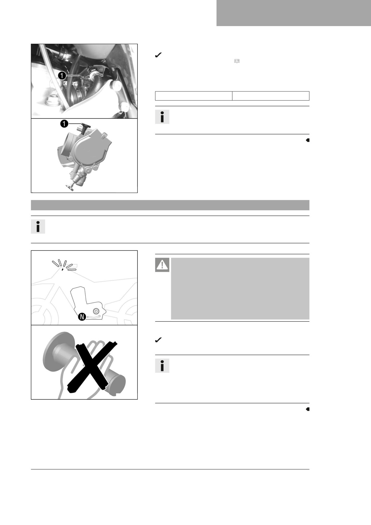
- Adjust the idle speed by turning idle speed adjusting
screw 1 using a suitable tachometer.
Guideline
Idle speed
2,250 … 2,350 rpm
Info
Turning counterclockwise lowers the idle speed.
Turning clockwise raises the idle speed.
A01063-10
16.6
Programming the throttle valve position
Info
If the control unit detects that the throttle valve position at idle speed needs to be reprogrammed, then
the malfunction indicator lamp flashes 2x per second.
Danger
Danger of poisoning Exhaust gases are toxic and
inhaling them may result in unconsciousness and
death.
- Always make sure there is sufficient ventilation
when running the engine.
- Use effective exhaust extraction when starting or
running the engine in an enclosed space.
- Allow the vehicle to run at idle speed.
The malfunction indicator lamp stops flashing once pro-
gramming is completed.
Info
If the engine becomes too warm, perform a cool-down
ride at medium speed.
After this, do not switch off the engine, but leave it
running at idle speed until the programming is fin-
H02263-10
ished.
115
16
TUNING THE ENGINE
16.7
Checking the basic position of the shift lever
Info
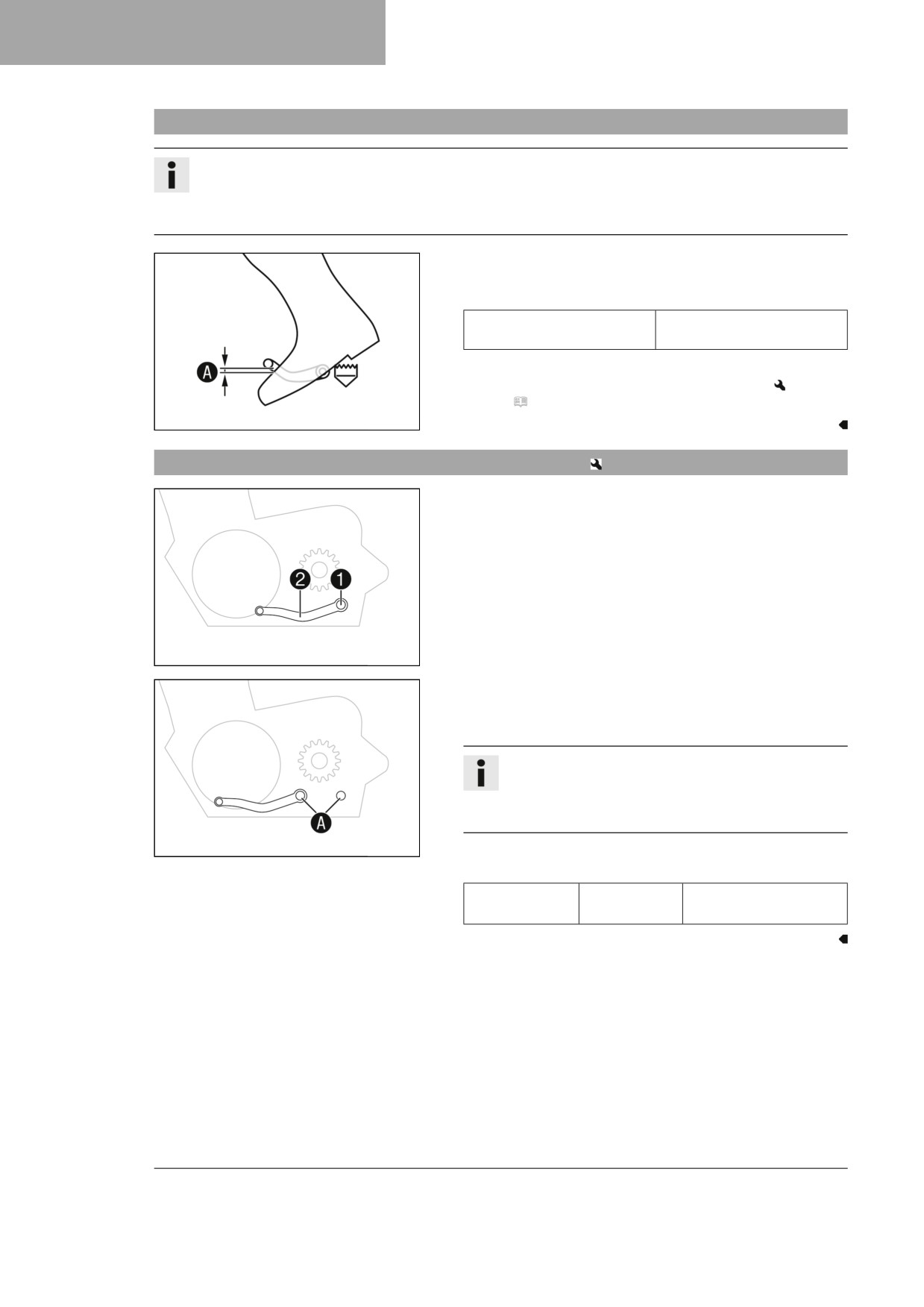
When driving, the shift lever must not touch the rider's boot when in the basic position.
If the shift lever is permanently touching the boot, the transmission will be subject to excessive load; this
can cause a malfunction of the quickshifter.
- Sit on the vehicle in the riding position and determine
distance A between the upper edge of your boot and the
shift lever.
Distance between shift lever
10 … 20 mm (0.39 …
and upper edge of boot
0.79 in)
» If the distance does not meet specifications:
- Adjust the basic position of the shift lever.
(
p. 116)
400692-10
16.8
Adjusting the basic position of the shift lever
- Remove screw 1 with the washers and take off shift
lever 2.
401950-12
- Clean gear teeth A of the shift lever and shift shaft.
- Mount the shift lever on the shift shaft in the required position
and engage gearing.
Info
The range of adjustment is limited.
The shift lever must not come into contact with any
other vehicle components during the shift procedure.
401951-10
- Mount and tighten screw 1 with washers.
Guideline
Screw, shift
M6
14 Nm (10.3 lbf ft)
lever
Loctite®243™
116
SERVICE WORK ON THE ENGINE
17
17.1
Changing the fuel screen
Danger
Fire hazard Fuel is highly flammable.
The fuel in the fuel tank expands when warm and can escape if overfilled.
- Do not fuel the vehicle in the vicinity of open flames or lit cigarettes.
- Switch off the engine for refueling.
- Make sure that no fuel is spilled; particularly not on hot parts of the vehicle.
- If any fuel is spilled, wipe it off immediately.
- Observe the specifications for refueling.
Warning
Danger of poisoning Fuel is harmful to health.
- Avoid skin, eye and clothing contact with fuel.
- Immediately consult a doctor if you swallow fuel.
- Do not inhale fuel vapors.
- Rinse the affected area immediately with plenty of water in the event of contact with the skin.
- Rinse the eyes thoroughly with water, and consult a doctor in case of fuel contact with the eyes.
- Change your clothing if fuel spills on them.
Note
Environmental hazard Improper handling of fuel is a danger to the environment.
- Do not allow fuel to enter the groundwater, the soil, or the sewage system.
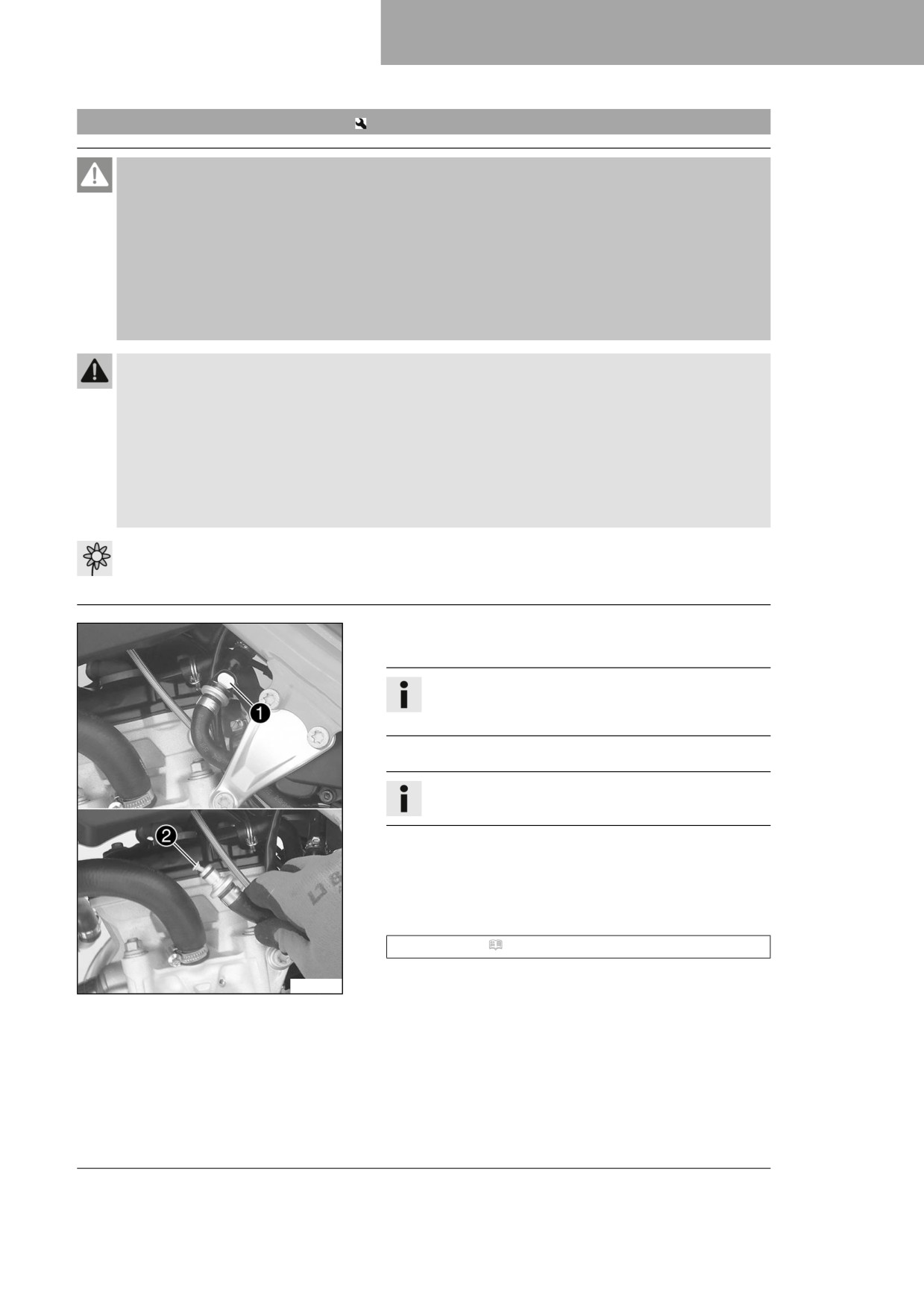
- Clean quick release coupling 1 thoroughly with
compressed air.
Info
Under no circumstances should dirt enter into the fuel
line. Dirt in the fuel line clogs the injection valve!
- Disconnect the quick release coupling.
Info
Remaining fuel may flow out of the fuel hose.
- Pull fuel screen 2 out of the connecting piece.
- Insert the new fuel screen all the way into the connecting
piece.
- Spray silicone spray onto a lint-free cleaning cloth and lightly
lubricate the O-ring of the quick-release coupling.
Silicone spray ( p. 143)
- Join quick release coupling 1.
F03737-10
117
17
SERVICE WORK ON THE ENGINE
Danger
Danger of poisoning Exhaust gases are toxic and
inhaling them may result in unconsciousness and
death.
- Always make sure there is sufficient ventilation
when running the engine.
- Use effective exhaust extraction when starting or
running the engine in an enclosed space.
- Start the engine and check the response.
17.2
Checking the engine oil level
Info
The engine oil level can be checked when the engine is cold or warm.
Preparatory work
- Stand the motorcycle upright on a horizontal surface.
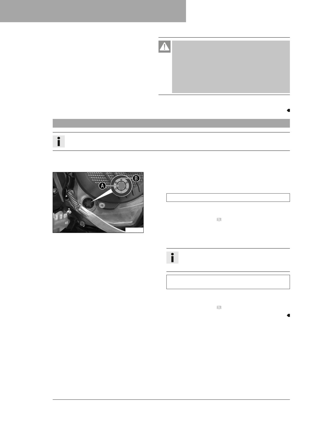
Condition
The engine is cold.
- Check the engine oil level.
The engine oil reaches the middle of level viewer A.
» If the engine oil does not reach the middle of the level
viewer:
- Add engine oil. ( p. 121)
Condition
A01079-10
The engine is at operating temperature.
- Check the engine oil level.
Info
After switching off the engine, wait one minute
before checking the level.
The engine oil level is between the middle of the level
viewer A and the upper edge of the level viewer B.
» If the engine oil does not reach the middle of level
viewer A:
- Add engine oil. ( p. 121)
118
SERVICE WORK ON THE ENGINE
17
17.3
Changing the engine oil and oil filter, cleaning the oil screen
Warning
Danger of scalding Engine and gear oil get hot when the motorcycle is operated.
- Wear suitable protective clothing and safety gloves.
- In the event of scalding, rinse the area affected immediately with lukewarm water.
Note
Environmental hazard Hazardous substances cause environmental damage.
- Dispose of oils, grease, filters, fuel, cleaning agents, brake fluid, etc., correctly and in compliance
with the applicable regulations.
Info
Drain the engine oil while the engine is at operating temperature.
Preparatory work
- Park the motorcycle on a level surface.
Main work
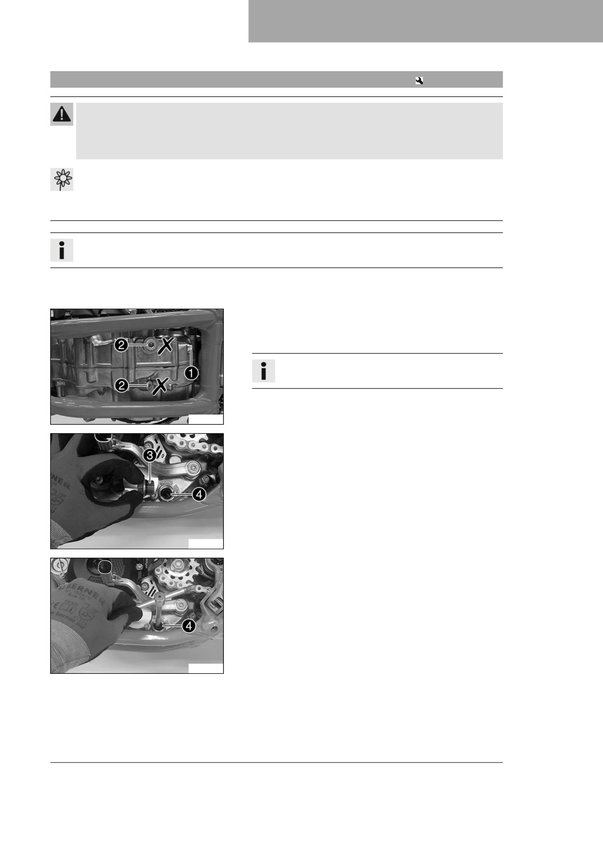
- Position an appropriate container under the engine.
- Remove oil drain plug 1 with the magnet and seal ring.
Info
Do not remove screws 2.
H04991-10
- Remove plug 3 with oil screen 4 and O-ring.
- Allow the engine oil to drain completely.
- Thoroughly clean the parts and the sealing surfaces.
H04992-10
- Position oil screen 4 with the O-rings on a pin wrench.
- Position the pin wrench through the drill hole of the screw
plug in the opposite section of the engine case.
- Push the oil screen all the way into the engine case.
H04993-10
119
17
SERVICE WORK ON THE ENGINE
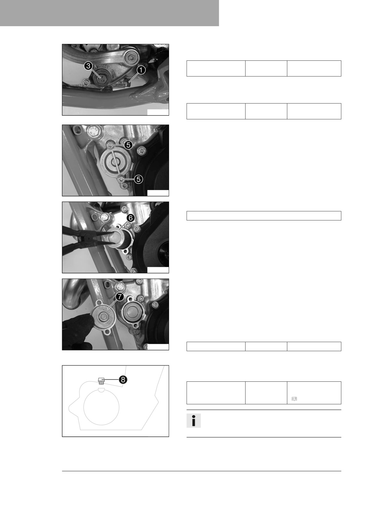
- Mount and tighten screw plug 3 with the O-ring.
Guideline
Screw plug, oil
M20x1.5
15 Nm (11.1 lbf ft)
screen
- Mount and tighten oil drain plug 1 with the magnet and a
new seal ring.
Guideline
Oil drain plug with
M12x1.5
20 Nm (14.8 lbf ft)
H04994-10
magnet
- Remove screws 5. Take off the oil filter cover with the O-
ring.
H04995-10
- Pull oil filter 6 out of the oil filter housing.
Lock ring plier (51012011000)
- Allow the engine oil to drain completely.
- Thoroughly clean the parts and the sealing surfaces.
H04996-10
- Lay the motorcycle on its side and fill the oil filter housing to
about ⅓ full with engine oil.
- Fill the oil filter with engine oil and position the oil filter in the
housing.
- Oil the O-ring of the oil filter cover and mount it together with
oil filter cover 7.
- Mount and tighten the screws.
Guideline
H04997-10
Screw, oil filter cover
M6
10 Nm (7.4 lbf ft)
– Stand the motorcycle upright.
- Remove filler plug 8 with the O-ring, and fill up with engine
oil.
Engine oil
1.0 l (1.1 qt.)
Engine oil (SAE
10W/50)
(
p. 140)
Info
Too little engine oil or poor-quality engine oil will result
in premature wear of the engine.
401955-12
- Mount and tighten the filler plug together with the O-ring.
120