HUSQVARNA FC 250. OWNER'S MANUAL (2024) - page 4
SERVICE WORK ON THE ENGINE
17
Danger
Danger of poisoning Exhaust gases are toxic and
inhaling them may result in unconsciousness and
death.
- Always make sure there is sufficient ventilation
when running the engine.
- Use effective exhaust extraction when starting or
running the engine in an enclosed space.
- Start the engine and check it for leaks.
Finishing work
- Check the engine oil level. ( p. 118)
17.4
Adding engine oil
Info
Too little engine oil or poor-quality engine oil will result in premature wear of the engine.
Main work
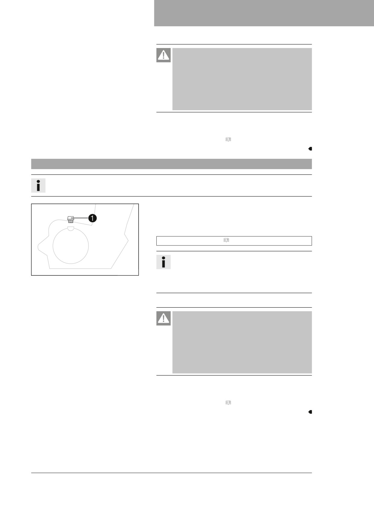
- Remove filler plug 1 with the O-ring.
- Add the same engine oil used when the last oil change was
carried out.
Engine oil (SAE 10W/50) ( p. 140)
Info
For optimal performance of the engine oil, do not mix
401955-10
different types of engine oil.
Husqvarna Motorcycles recommends changing the
engine oil.
- Mount and tighten the filler plug together with the O-ring.
Danger
Danger of poisoning Exhaust gases are toxic and
inhaling them may result in unconsciousness and
death.
- Always make sure there is sufficient ventilation
when running the engine.
- Use effective exhaust extraction when starting or
running the engine in an enclosed space.
- Start the engine and check for leaks.
Finishing work
- Check the engine oil level. ( p. 118)
121
18
CLEANING, CARE
18.1
Cleaning the motorcycle
Note
Material damage Components become damaged or destroyed if a pressure cleaner is used incorrectly.
The high pressure forces water into the electrical components, connectors, throttle cables, and bearings, etc.
Pressure which is too high causes malfunctions and destroys components.
-
Do not direct the water jet directly on to electrical components, connectors, throttle cables or bearings.
–
Maintain a minimum distance between the nozzle of the pressure cleaner and the component.
Minimum clearance
60 cm (23.6 in)
Note
Environmental hazard Hazardous substances cause environmental damage.
- Dispose of oils, grease, filters, fuel, cleaning agents, brake fluid, etc., correctly and in compliance
with the applicable regulations.
Info
To maintain the value and appearance of the motorcycle over a long period, clean it regularly.
Avoid direct sunshine when cleaning the motorcycle.
-
Close off exhaust system to keep water from entering.
–
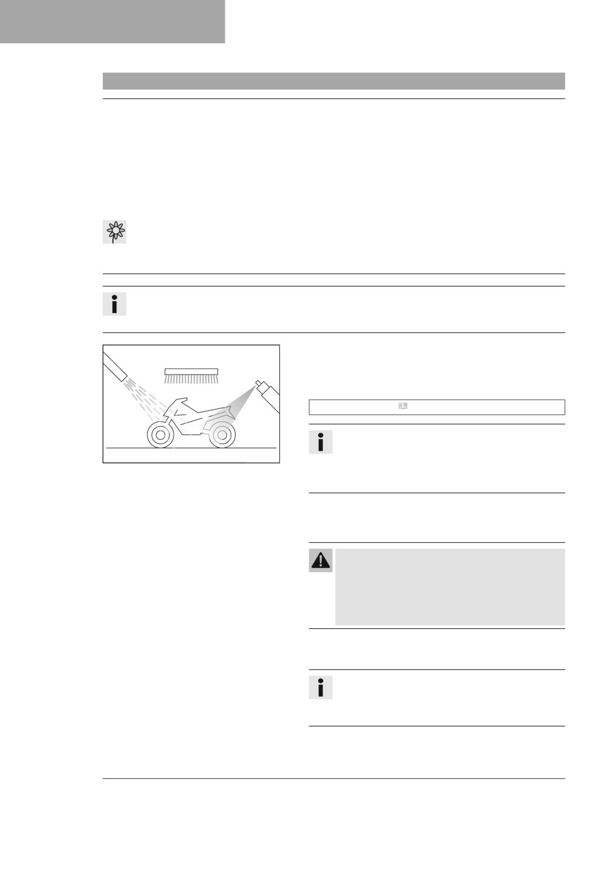
Remove loose dirt first with a soft jet of water.
–
Spray the heavily soiled parts with a normal commercial
motorcycle cleaner and clean using a brush.
Motorcycle cleaner ( p. 142)
Info
Use warm water containing normal motorcycle cleaner
401061-01
and a soft sponge.
Never apply motorcycle cleaner to a dry vehicle;
always rinse the vehicle with water first.
-
After rinsing the motorcycle with a gentle spray of water,
allow it to dry thoroughly.
-
Remove the closure of the exhaust system.
Warning
Danger of accidents Moisture and dirt impair the
brake system.
- Brake carefully several times to dry out and
remove dirt from the brake linings and the brake
discs.
-
After cleaning, ride the vehicle a short distance until the
engine warms up.
Info
The heat produced causes water at inaccessible loca-
tions in the engine and on the brake system to evapo-
rate.
-
Push back the protection caps of the handlebar controls to
allow any water that has penetrated to evaporate.
122
CLEANING, CARE
18
– After the motorcycle has cooled down, lubricate all moving
parts and pivot points.
- Clean the chain. ( p. 72)
- Treat bare metal (except for brake discs and the exhaust sys-
tem) with a corrosion inhibitor.
Preserving materials for paints, metal and rubber
(
p. 142)
– Treat all plastic parts and powder-coated parts with a mild
cleaning and care product.
Special cleaner for glossy and matte paint finishes, metal
and plastic surfaces ( p. 143)
123
19
STORAGE
19.1
Storage
Warning
Danger of poisoning Fuel is harmful to health.
- Avoid skin, eye and clothing contact with fuel.
- Immediately consult a doctor if you swallow fuel.
- Do not inhale fuel vapors.
- Rinse the affected area immediately with plenty of water in the event of contact with the skin.
- Rinse the eyes thoroughly with water, and consult a doctor in case of fuel contact with the eyes.
- Change your clothing if fuel spills on them.
- Keep fuels correctly in a suitable canister, and out of the reach of children.
Info
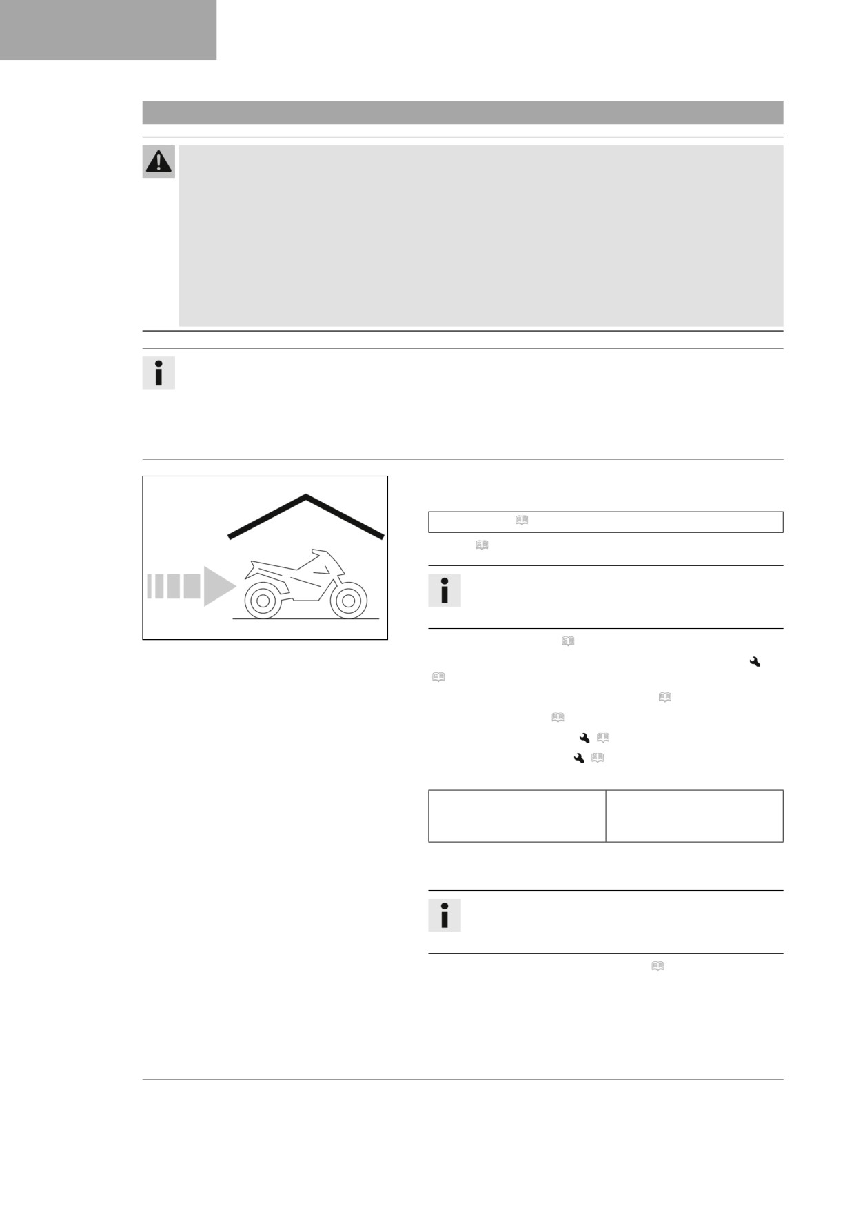
If you plan to garage the motorcycle for a longer period, perform the following steps or have them per-
formed.
Before storing the motorcycle, check all parts for function and wear. If service, repairs, or replacements
are necessary, you should do this during the storage period (less workshop overload). In this way, you
can avoid long workshop waiting times at the start of the new season.
-
When refueling for the last time before taking the motorcycle
out of service, add fuel additive.
Fuel additive ( p. 142)
-
Refuel. ( p. 32)
Tip
Fill the fuel tank completely as specified, using fuel
with the lowest possible ethanol content.
401058-01
-
Clean the motorcycle. ( p. 122)
–
Change the engine oil and oil filter, clean the oil screen.
(
p. 119)
–
Check the antifreeze and coolant level. ( p. 107)
–
Check tire pressure. ( p. 99)
–
Remove the 12-V battery.
(
p. 101)
–
Charge the 12-V battery.
(
p. 103)
Guideline
Ideal charging and storage
10 … 20 °C (50 … 68 °F)
temperature of the lithium-
ion battery
-
Store the vehicle in a dry location that is not subject to large
fluctuations in temperature.
Info
Husqvarna Motorcycles recommends jacking up the
motorcycle.
-
Raise the motorcycle with a lift stand. ( p. 49)
–
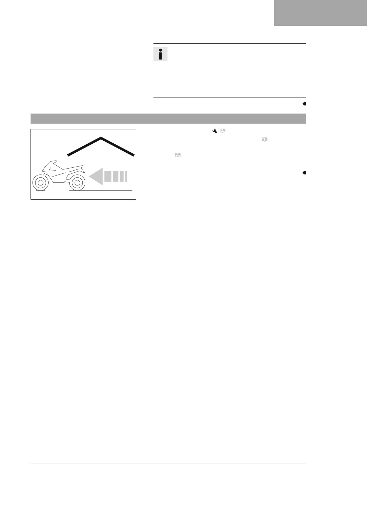
Cover the vehicle with a tarp or a similar cover that is perme-
able to air.
124
STORAGE 19
Info
Do not use non-porous materials since they prevent
humidity from escaping, thus causing corrosion.
Avoid running the engine for a short time only. Since
the engine cannot warm up properly, the water vapor
produced during combustion condenses and causes
valves and the exhaust system to rust.
19.2
Putting into operation after storage
- Install the 12-V battery.
(
p. 102)
– Remove the motorcycle from the lift stand. ( p. 49)
- Perform checks and maintenance measures when preparing
for use. ( p. 26)
- Take a test ride.
401059-01
125
20
TROUBLESHOOTING
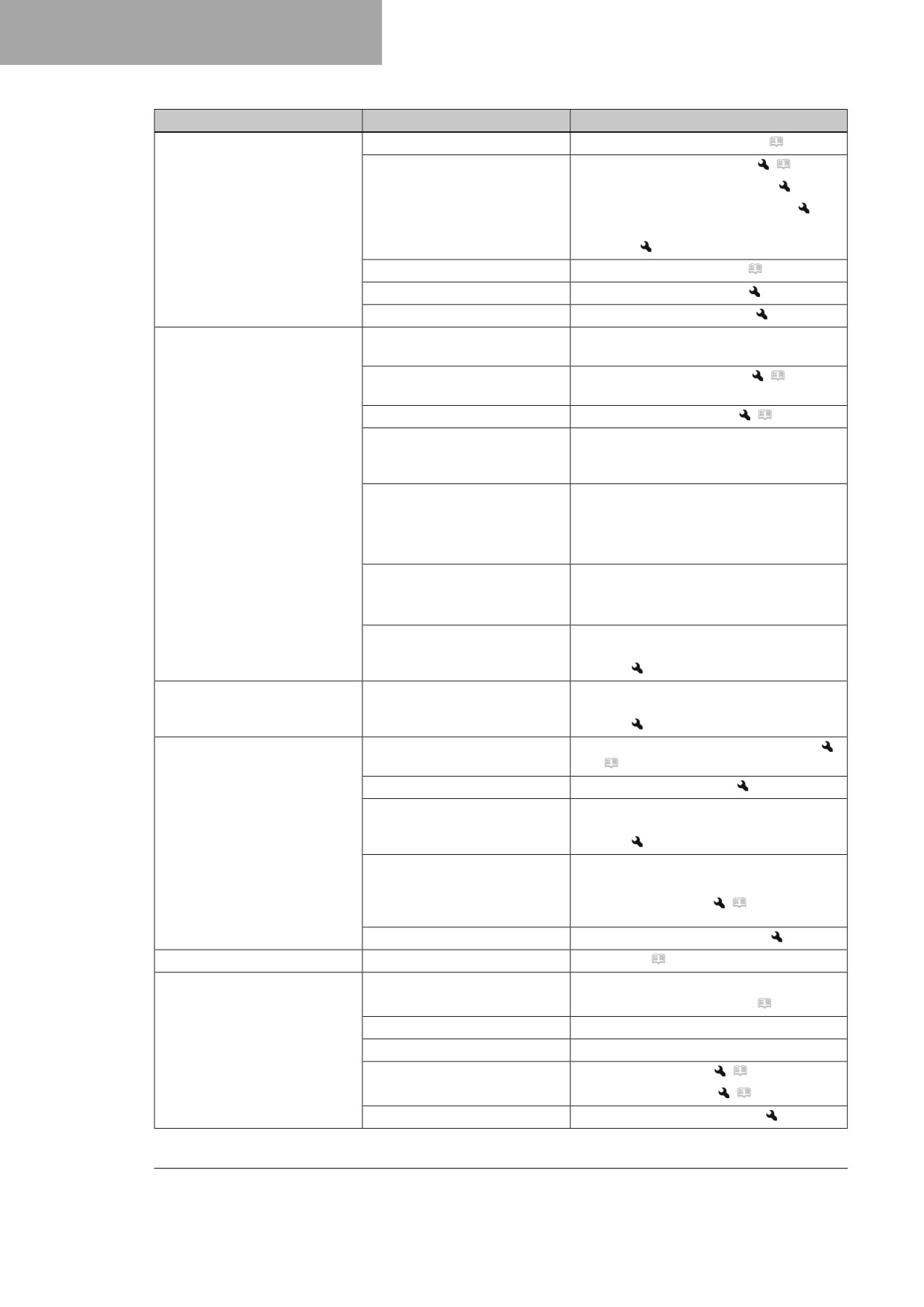
Faults
Possible cause
Action
The engine does not turn when
Operating error
-
Carry out start procedure. ( p. 26)
the start button is pressed
12-V battery discharged
-
Charge the 12-V battery.
(
p. 103)
–
Check the charging voltage.
–
Check the open-circuit current.
–
Check the stator winding of the alter-
nator.
Main fuse blown
-
Change the main fuse. ( p. 104)
Faulty starter relay
-
Check the starter relay.
Faulty starter motor
-
Check the starter motor.
Engine turns but does not start
Quick release coupling not
-
Join quick release coupling.
joined
Fuel screen in the quick
-
Change the fuel screen.
(
p. 117)
release coupling is clogged
Idle speed is not set correctly
-
Adjust the idle speed.
(
p. 114)
Spark plug sooty or wet
-
Clean and dry the spark plug and
spark plug connector, or change if
necessary.
Plug gap of spark plug too
-
Adjust plug gap.
wide
Guideline
Spark plug electrode gap
1.0 mm (0.039 in)
Short-circuit cable in wiring
-
Check the wiring harness. (visual
harness frayed, stop button
check)
faulty
-
Check the electrical system.
Malfunction in the electronic
-
Read out the fault memory using the
fuel injection
Husqvarna Motorcycles diagnostics
tool.
Engine does not speed up
Malfunction in the electronic
-
Read out the fault memory using the
fuel injection
Husqvarna Motorcycles diagnostics
tool.
Engine has too little power
Air filter is very dirty
-
Clean the air filter and air filter box.
(
p. 65)
Fuel filter is very dirty
-
Change the fuel filter.
Malfunction in the electronic
-
Read out the fault memory using the
fuel injection
Husqvarna Motorcycles diagnostics
tool.
Exhaust system leaks,
-
Check exhaust system for damage.
deformed or too little glass
–
Change the glass fiber yarn filling of
fiber yarn filling in main
the main silencer.
(
p. 68)
silencer
Valve clearance too little
-
Adjust the valve clearance.
Engine dies during the trip
Lack of fuel
-
Refuel. ( p. 32)
Engine overheats
Too little coolant in cooling
-
Check the cooling system for leakage.
system
-
Check the coolant level. ( p. 108)
Too little air stream
-
Switch off the engine when standing.
Radiator fins very dirty
-
Clean the radiator fins.
Foam formation in cooling sys-
-
Drain the coolant.
(
p. 108)
tem
-
Refill with coolant.
(
p. 109)
Bent radiator hose
-
Change the radiator hose.
126
TROUBLESHOOTING
20
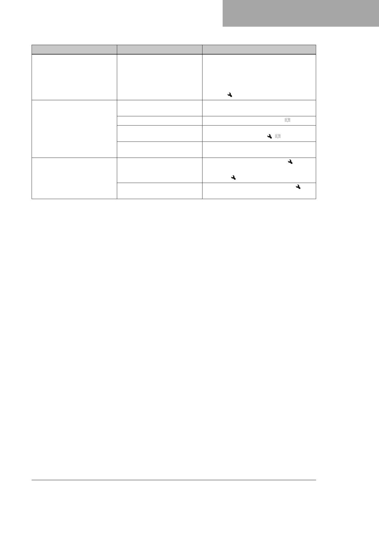
Faults
Possible cause
Action
Malfunction indicator lamp
Error in the electronic fuel
- Check the wiring for damage and the
lights up or flashes
injection
electrical plug-in connections for cor-
rosion and damage.
- Read out the fault memory using the
Husqvarna Motorcycles diagnostics
tool.
High oil consumption
Engine vent hose bent
- Route the vent hose without bends or
change it if necessary.
Engine oil level too high
- Check the engine oil level. ( p. 118)
Engine oil too thin (low viscosi-
- Change the engine oil and oil filter,
ty)
clean the oil screen.
(
p. 119)
Piston or cylinder worn
- Measure the piston/cylinder mounting
clearance.
12-V battery discharged
12 V battery is not charging
- Check the charging voltage.
- Check the stator winding of the alter-
nator.
Unwanted electrical power
- Check the open-circuit current.
consumer
127
21
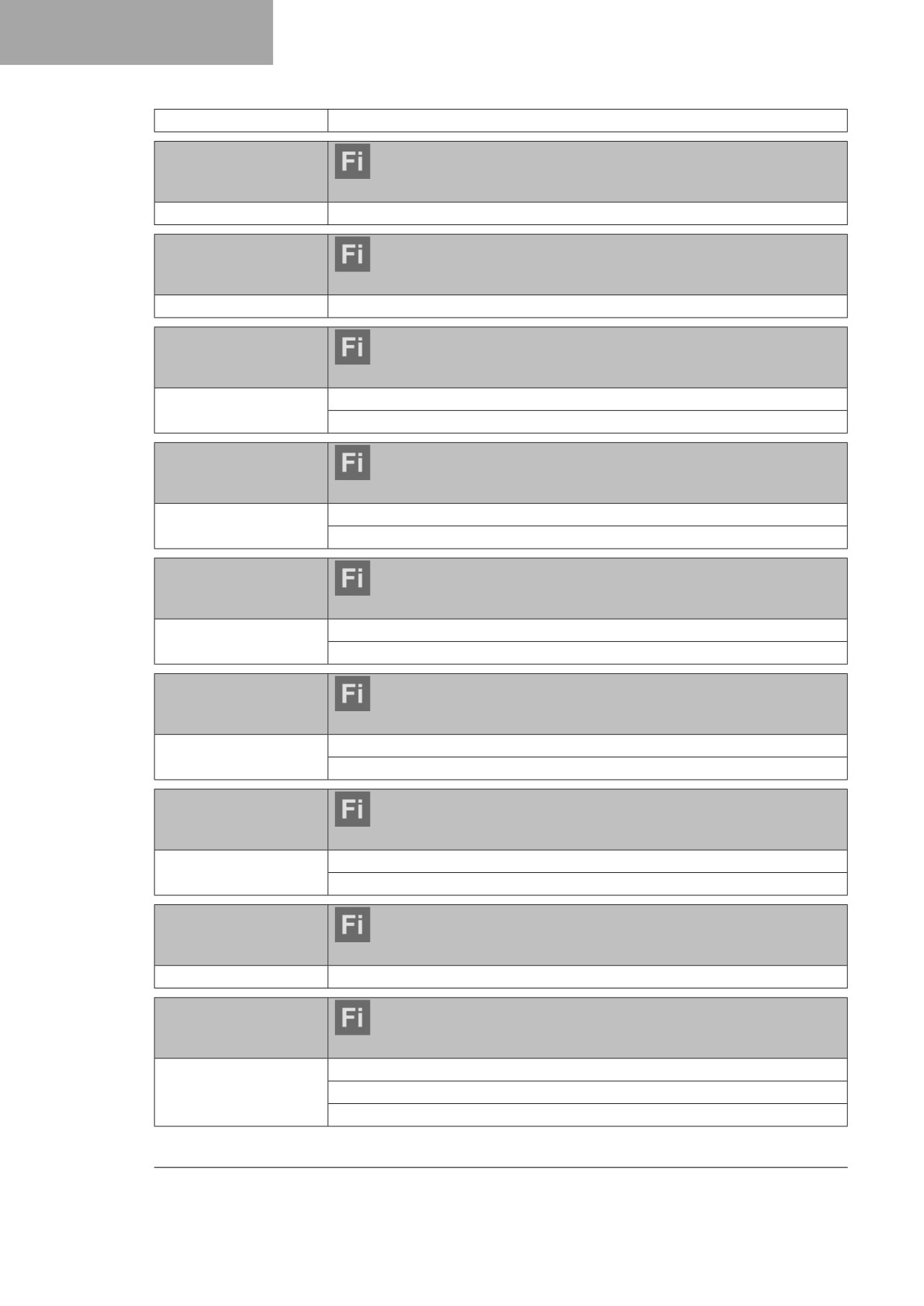
BLINK CODE
Error level condition
Combination switch, left side - buttons pressed longer than 20
seconds
Blink code for malfunc-
tion indicator lamp
Malfunction indicator lamp flashes continuously
Error level condition
THREF - malfunction
Blink code for malfunc-
tion indicator lamp
02 Malfunction indicator lamp flashes 2x short
Error level condition
Crankshaft speed sensor - circuit fault
Blink code for malfunc-
tion indicator lamp
06 Malfunction indicator lamp flashes 6x short
Error level condition
Throttle valve position sensor circuit A - input signal too low
Throttle valve position sensor circuit A - input signal too high
Blink code for malfunc-
tion indicator lamp
09 Malfunction indicator lamp flashes 9x short
Error level condition
Induction manifold pressure sensor - input signal too high
Induction manifold pressure sensor - input signal too low
Blink code for malfunc-
tion indicator lamp
12 Malfunction indicator lamp flashes 1x long, 2x short
Error level condition
Coolant temperature sensor - input signal too high
Coolant temperature sensor - input signal too low
Blink code for malfunc-
tion indicator lamp
13 Malfunction indicator lamp flashes 1x long, 3x short
Error level condition
Intake air temperature sensor - input signal too high
Intake air temperature sensor - input signal too low
Blink code for malfunc-
tion indicator lamp
15 Malfunction indicator lamp flashes 1x long, 5x short
Error level condition
Tilt sensor - input signal too low
Tilt sensor - open / input signal too high
Blink code for malfunc-
tion indicator lamp
21 Malfunction indicator lamp flashes 2x long, 1x short
Error level condition
Battery voltage - input voltage too high
Blink code for malfunc-
tion indicator lamp
22 Malfunction indicator lamp flashes 2x long, 2x short
Error level condition
Gear position sensor - input signal too low
Gear position sensor - input signal too high
Gear position sensor - malfunction
128
BLINK CODE
21
Blink code for malfunc-
tion indicator lamp
33 Malfunction indicator lamp flashes 3x long, 3x short
Error level condition
Injection valve cylinder 1 - circuit fault
Blink code for malfunc-
tion indicator lamp
37 Malfunction indicator lamp flashes 3x long, 7x short
Error level condition
Ignition coil - circuit fault
Blink code for malfunc-
tion indicator lamp
41 Malfunction indicator lamp flashes 4x long, 1x short
Error level condition
Fuel pump controller - short circuit to ground/open circuit
Fuel pump controller - short circuit to plus
Blink code for malfunc-
tion indicator lamp
65 Malfunction indicator lamp flashes 6x long, 5x short
Error level condition
EEPROM - malfunction
Blink code for malfunc-
tion indicator lamp
91 Malfunction indicator lamp flashes 9x long, 1x short
Error level condition
CAN bus communication - faulty
129
22
TECHNICAL SPECIFICATIONS
22.1
Engine
Design
1-cylinder 4-stroke engine, water-cooled
Displacement
249.91 cm³ (15.2505 cu in)
Stroke
48.5 mm (1.909 in)
Bore
81 mm (3.19 in)
Compression ratio
14.5:1
Idle speed
2,250 … 2,350 rpm
Control
DOHC, four valves controlled via cam lever, drive via
timing chain
Valve diameter, intake
32.5 mm (1.28 in)
Valve diameter, exhaust
27.5 mm (1.083 in)
Valve clearance
Intake at: 20 °C (68 °F)
0.08 … 0.15 mm (0.0031 … 0.0059 in)
Exhaust at: 20 °C (68 °F)
0.12 … 0.19 mm (0.0047 … 0.0075 in)
Crankshaft bearing
2 cylinder bearings
Conrod bearing
Slide bearing
Piston pin bearing
Bearing bush
Pistons
Forged light alloy
Piston rings
1 compression ring, 1 oil scraper ring
Engine lubrication
Pressure circulation lubrication with 2 trochoidal
pumps
Primary transmission
24:72
Clutch
Multidisc clutch in oil bath/hydraulically activated
Gearbox
5-gear transmission, claw shifted
Transmission ratio
first-gear
13:32
second-gear
16:32
third-gear
17:28
fourth-gear
19:26
fifth-gear
21:25
Alternator
14 V, 70 W
Ignition
Contactless controlled fully electronic ignition with
digital ignition adjustment
Spark plug
NGK LMAR9AI-10
Spark plug electrode gap
1.0 mm (0.039 in)
Cooling
Water cooling, permanent circulation of coolant by
water pump
Starting aid
Starter motor
130
TECHNICAL SPECIFICATIONS
22
22.2
Engine tightening torques
Hose clip, intake flange
M4
3 Nm (2.2 lbf ft)
Nozzle, crank chamber ventilation
M4
2 Nm (1.5 lbf ft)
Loctite®243™
Oil nozzle for clutch lubrication
M4
2 Nm (1.5 lbf ft)
Loctite®243™
Oil nozzle for conrod bearing
M4
2 Nm (1.5 lbf ft)
lubrication
Loctite®243™
Oil nozzle for main bearing lubri-
M4
2 Nm (1.5 lbf ft)
cation
Loctite®243™
Screw, oil nozzle bent for piston
M4
2.5 Nm (1.84 lbf ft)
cooling
Loctite®243™
Alternator cover grub screw
M5
2 Nm (1.5 lbf ft)
Loctite®243™
Locking screw for bearing
M5
6 Nm (4.4 lbf ft)
Loctite®243™
Oil channel screw plug in alterna-
M5
2 Nm (1.5 lbf ft)
tor cover
Loctite®243™
Oil nozzle for cam lever lubrication
M5
3 Nm (2.2 lbf ft)
Loctite®243™
Oil nozzle, piston cooling
M5
2 Nm (1.5 lbf ft)
Loctite®243™
Screw, bearing bolt, oil pump idler
M5
6 Nm (4.4 lbf ft)
gear
Loctite®243™
Screw, clutch spring retainer
M5
6 Nm (4.4 lbf ft)
Screw, crankshaft speed sensor
M5
6 Nm (4.4 lbf ft)
Loctite®243™
Screw, gear position sensor
M5
5 Nm (3.7 lbf ft)
Loctite®243™
Screw, locking lever
M5
6 Nm (4.4 lbf ft)
Loctite®243™
Screw, oil pump cover
M5
6 Nm (4.4 lbf ft)
Loctite®243™
Screw, stator
M5
6 Nm (4.4 lbf ft)
Loctite®2701™
Nut, cylinder head
M6
10 Nm (7.4 lbf ft)
Nut, water pump impeller
M6
6 Nm (4.4 lbf ft)
Loctite®
243™ also in gap
between shaft and water pump
impeller
Screw, alternator cover
M6
10 Nm (7.4 lbf ft)
Screw, clutch cover
M6x25
10 Nm (7.4 lbf ft)
Screw, clutch slave cylinder
M6
10 Nm (7.4 lbf ft)
Screw, engine case
M6x55
10 Nm (7.4 lbf ft)
Screw, engine case
M6x70
10 Nm (7.4 lbf ft)
Screw, exhaust flange
M6
10 Nm (7.4 lbf ft)
Loctite®243™
131
22
TECHNICAL SPECIFICATIONS
Screw, guide rail
M6
10 Nm (7.4 lbf ft)
Loctite®243™
Screw, oil filter cover
M6
10 Nm (7.4 lbf ft)
Screw, outer clutch cover
M6x25
10 Nm (7.4 lbf ft)
Screw, outer clutch cover
M6x45
10 Nm (7.4 lbf ft)
Screw, shift drum locating
M6
10 Nm (7.4 lbf ft)
Loctite®243™
Screw, shift lever
M6
14 Nm (10.3 lbf ft)
Loctite®243™
Screw, starter motor
M6
10 Nm (7.4 lbf ft)
Screw, starter motor - intermedi-
M6
10 Nm (7.4 lbf ft)
ate gear
Loctite®243™
Screw, timing chain failure protec-
M6
10 Nm (7.4 lbf ft)
tion
Loctite®243™
Screw, valve cover
M6
8 Nm (5.9 lbf ft)
Screw, water pump cover
M6x25
10 Nm (7.4 lbf ft)
Screw, water pump cover
M6x40
10 Nm (7.4 lbf ft)
Stud, cylinder head
M6
6 Nm (4.4 lbf ft)
Loctite®243™
Screw, camshaft bearing bridge
M7x1
Tightening sequence:
Tighten diagonally.
1st tightening stage
5 Nm (3.7 lbf ft)
2nd tightening stage
14 Nm (10.3 lbf ft)
Lubricated with engine oil
Crankshaft clamp screw plug
M8
10 Nm (7.4 lbf ft)
Crankshaft locking bolt
M8
8 Nm (5.9 lbf ft)
Screw, tensioning rail
M8
15 Nm (11.1 lbf ft)
Loctite®243™
Screw, engine sprocket
M10
60 Nm (44.3 lbf ft)
Loctite®243™
Plug, oil channel
M10x1
15 Nm (11.1 lbf ft)
Loctite®243™
Screw plug, cam lever axis
M10x1
10 Nm (7.4 lbf ft)
Screw, rotor
M10x1
70 Nm (51.6 lbf ft)
Collar and thread oiled / cone
degreased
Screw, unlocking of timing chain
M10x1
8 Nm (5.9 lbf ft)
tensioner
Spark plug
M10x1
12 Nm (8.9 lbf ft)
Coolant temperature sensor
M10x1.25
12 Nm (8.9 lbf ft)
132
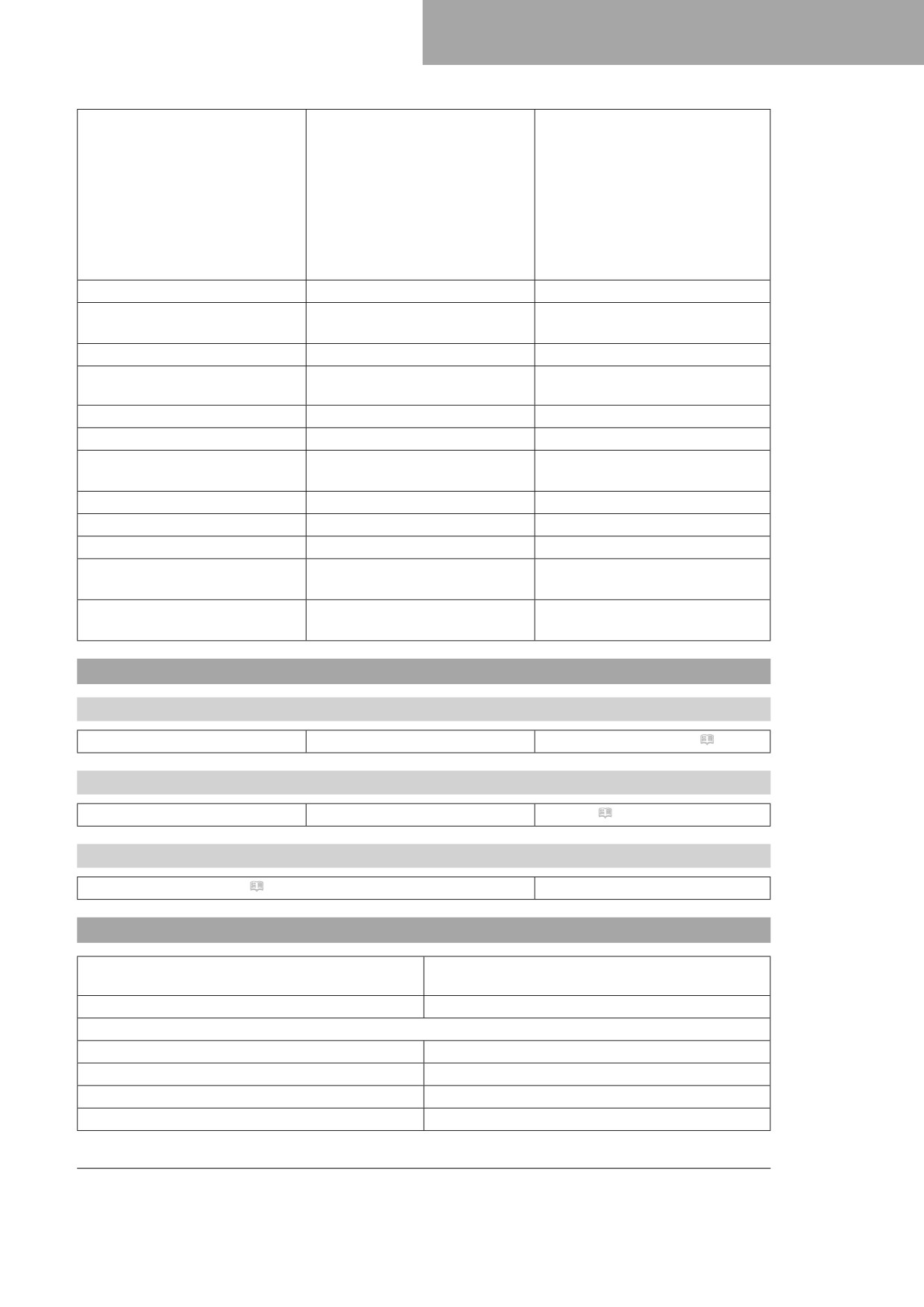
TECHNICAL SPECIFICATIONS
22
Nut, cylinder head
M10x1.25
Tightening sequence:
Tighten diagonally.
1st tightening stage
10 Nm (7.4 lbf ft)
2nd tightening stage
30 Nm (22.1 lbf ft)
3rd tightening stage
180°
Thread oiled
Screw, cylinder head
M10x1.25
20 Nm (14.8 lbf ft)
Stud, cylinder head
M10x1.25
20 Nm (14.8 lbf ft)
Loctite®243™
Oil drain plug with magnet
M12x1.5
20 Nm (14.8 lbf ft)
Screw plug, oil pressure control
M12x1.5
20 Nm (14.8 lbf ft)
valve
Oil drain plug
M14x1.5
15 Nm (11.1 lbf ft)
Nut, inner clutch hub
M18x1.5
100 Nm (73.8 lbf ft)
Nut, primary gear wheel
M18LHx1.5
120 Nm (88.5 lbf ft)
Loctite®243™
Screw plug, oil screen
M20x1.5
15 Nm (11.1 lbf ft)
Plug, timing chain tensioner
M24x1.5
40 Nm (29.5 lbf ft)
Screw, alternator cover
M24x1.5
18 Nm (13.3 lbf ft)
Filler plug
M24x3
hand-tight
Fixing nut for main bearing inner
M27x1
60 Nm (44.3 lbf ft)
ring
Loctite®243™
22.3
Capacities
22.3.1
Engine oil
Engine oil
1.0 l (1.1 qt.)
Engine oil (SAE 10W/50) ( p. 140)
22.3.2
Coolant
Coolant
0.90 l (0.95 qt.)
Coolant ( p. 140)
22.3.3
Fuel
Super unleaded (ROZ 95) (
p. 141)
7.2 l (1.9 US gal)
22.4
Chassis
Frame
Central tube frame made of chrome molybdenum
steel tubing
Fork
WP XACT AER
Suspension travel
front
305 mm (12.01 in)
rear
293 mm (11.54 in)
Fork offset
22 mm (0.87 in)
Shock absorber
WP XACT LDS
133
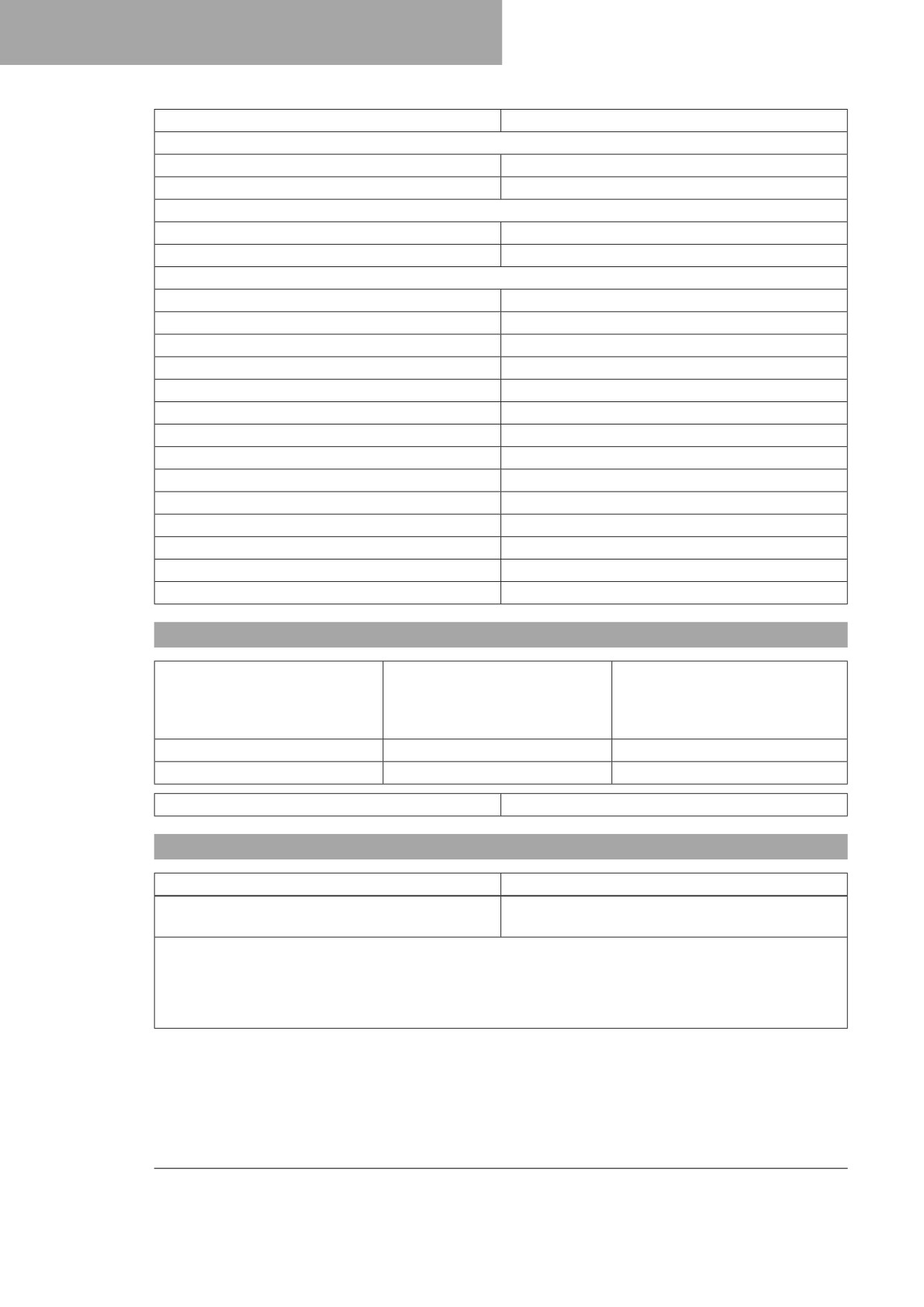
22
TECHNICAL SPECIFICATIONS
Brake system
Disc brakes, floating brake calipers
Brake discs - diameter
front
260 mm (10.24 in)
rear
220 mm (8.66 in)
Brake discs - wear limit
front
2.5 mm (0.098 in)
rear
3.5 mm (0.138 in)
Offroad tire pressure
front
1.0 bar (15 psi)
rear
1.0 bar (15 psi)
Secondary ratio (FC 250 EU)
14:52
Secondary ratio (FC 250 US)
14:51
Chain
5/8 x 1/4"
Available rear sprockets
47, 48, 49, 50, 51, 52
Steering head angle
63.9°
Wheelbase
1,490 ± 10 mm (58.66
±
0.39
in)
Seat height, unloaded
939 mm (36.97 in)
Ground clearance, unloaded
336 mm (13.23 in)
Weight without fuel, approx.
101.2 kg (223.1 lb.)
Maximum permissible front axle load
145 kg (320 lb.)
Maximum permissible rear axle load
190 kg (419 lb.)
Maximum permissible overall weight
335 kg (739 lb.)
22.5
Electrical system
12 V battery
HJTZ5S-FP-C
Lithium-ion battery
Battery voltage: 12 V
Nominal capacity: 2.0 Ah
Maintenance-free
Fuse
58011109110
10 A
Fuse
58011109105
5A
Combination instrument lighting and indicator lamps
LED
22.6
Tires
Front tire
Rear tire
80/100 - 21 51M TT
110/90 - 19 62M TT
Dunlop GEOMAX MX-33SF
Dunlop GEOMAX MX-33
The tires specified represent one of the possible series production tires. For alternative manufacturers, if any,
contact an authorized dealer or qualified tire dealership. If local road approval regulations apply, these and
the respective technical specifications must be observed. Additional information is available in the Service
section under:
134
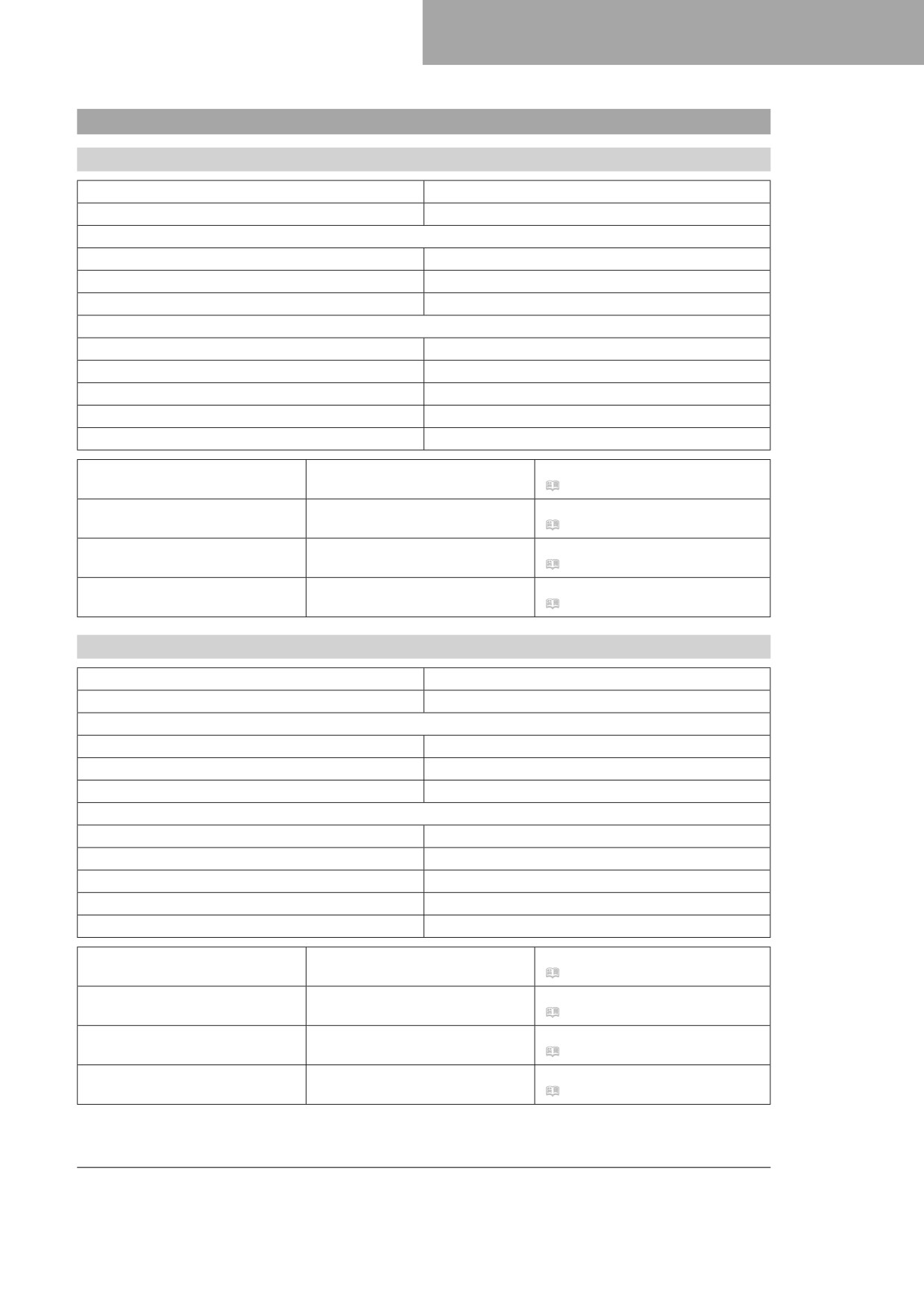
TECHNICAL SPECIFICATIONS
22
22.7
Fork
22.7.1
FC 250 EU
Fork article number
A360C105X406000
Fork
WP XACT AER
Compression damping
Comfort
17 clicks
Standard
12 clicks
Sport
7 clicks
Rebound damping
Comfort
17 clicks
Standard
12 clicks
Sport
7 clicks
Air pressure
10.3 bar (149 psi)
Fork length
940 mm (37.01 in)
Oil capacity external mechanism
240+10
− 50 ml (8.11−1.69 fl. oz.)
Fork oil (SAE 4) (48601166S1)
right
(
p. 141)
Oil capacity external mechanism
240+10
− 50 ml (8.11−1.69 fl. oz.)
Fork oil (SAE 4) (48601166S1)
left
(
p. 141)
Oil capacity, right cartridge
370 ml (12.51 fl. oz.)
Fork oil (SAE 4) (48601166S1)
(
p. 141)
Grease capacity, left cartridge
5 g (0.18 oz)
Special grease (00062010053)
(
p. 143)
22.7.2
FC 250 US
Fork article number
A360C155X406000
Fork
WP XACT AER
Compression damping
Comfort
17 clicks
Standard
12 clicks
Sport
7 clicks
Rebound damping
Comfort
23 clicks
Standard
18 clicks
Sport
13 clicks
Air pressure
10.5 bar (152 psi)
Fork length
940 mm (37.01 in)
Oil capacity external mechanism
240+10
− 50 ml (8.11−1.69 fl. oz.)
Fork oil (SAE 4) (48601166S1)
right
(
p. 141)
Oil capacity external mechanism
240+10
− 50 ml (8.11−1.69 fl. oz.)
Fork oil (SAE 4) (48601166S1)
left
(
p. 141)
Oil capacity, right cartridge
370 ml (12.51 fl. oz.)
Fork oil (SAE 4) (48601166S1)
(
p. 141)
Grease capacity, left cartridge
5 g (0.18 oz)
Special grease (00062010053)
(
p. 143)
135
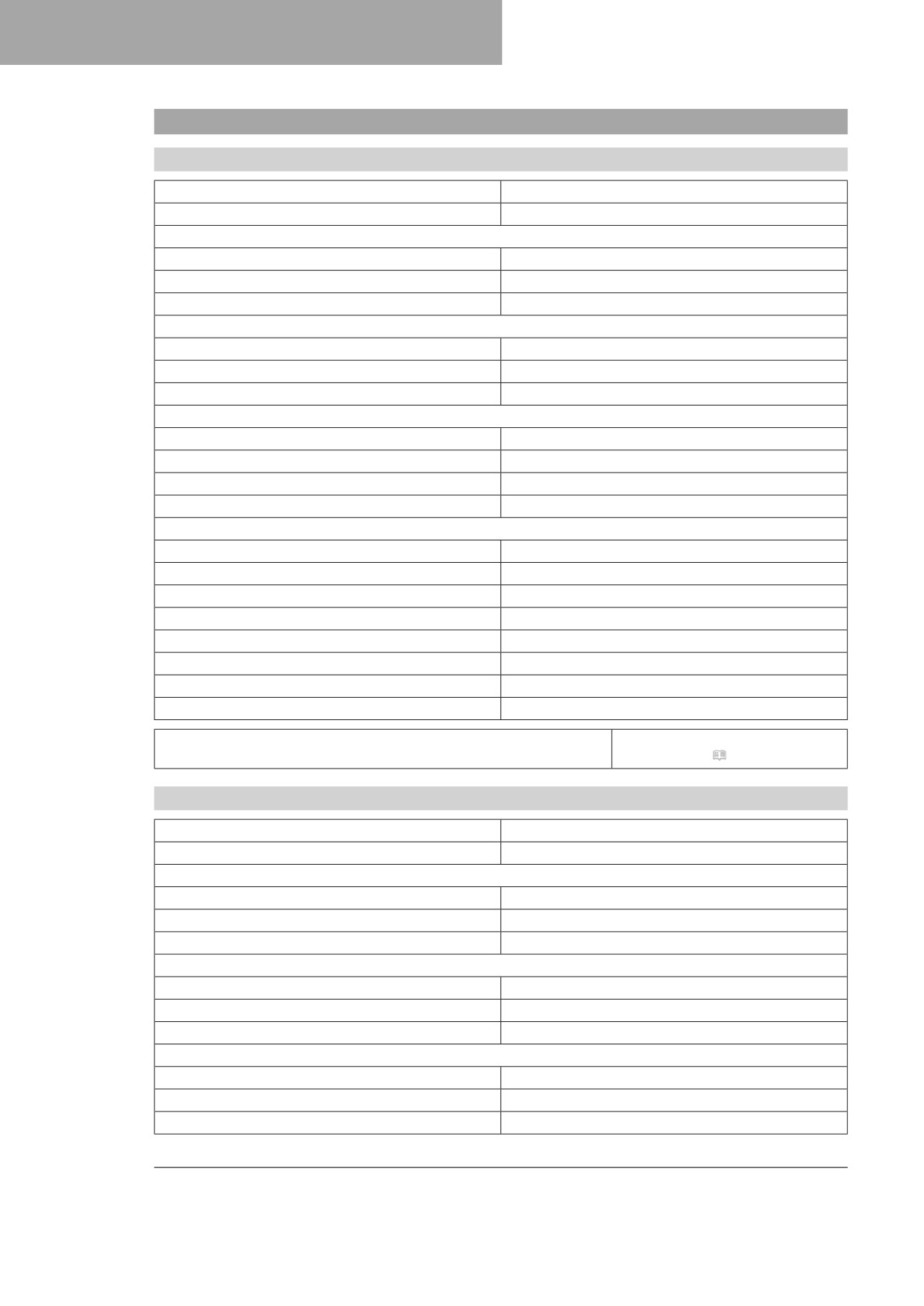
22
TECHNICAL SPECIFICATIONS
22.8
Shock absorber
22.8.1
FC 250 EU
Shock absorber article number
A360C405X408000
Shock absorber
WP XACT LDS
Lowspeed compression damping
Comfort
17 clicks
Standard
15 clicks
Sport
13 clicks
Highspeed compression damping
Comfort
2 turns
Standard
1.5 turns
Sport
1 turn
Rebound damping
Comfort
17 clicks
Standard
15 clicks
Sport
13 clicks
Spring preload
8 mm (0.31 in)
Spring rate
Weight of rider: 65 … 75 kg (143
… 165
lb.)
42 N/mm (240 lb/in)
Weight of rider: 75 … 85 kg (165
… 187
lb.)
45 N/mm (257 lb/in)
Weight of rider: 85 … 95 kg (187
… 209
lb.)
48 N/mm (274 lb/in)
Spring length
240 mm (9.45 in)
Gas pressure
10 bar (145 psi)
Static sag
35 mm (1.38 in)
Riding sag
105 mm (4.13 in)
Fitted length
456.3 mm (17.965 in)
Shock absorber oil
Shock absorber fluid (SAE
2.5)
(50180751S1) ( p. 141)
22.8.2
FC 250 US
Shock absorber article number
A360C455X408000
Shock absorber
WP XACT LDS
Lowspeed compression damping
Comfort
17 clicks
Standard
15 clicks
Sport
13 clicks
Highspeed compression damping
Comfort
2 turns
Standard
1.5 turns
Sport
1 turn
Rebound damping
Comfort
17 clicks
Standard
15 clicks
Sport
13 clicks
136
TECHNICAL SPECIFICATIONS
22
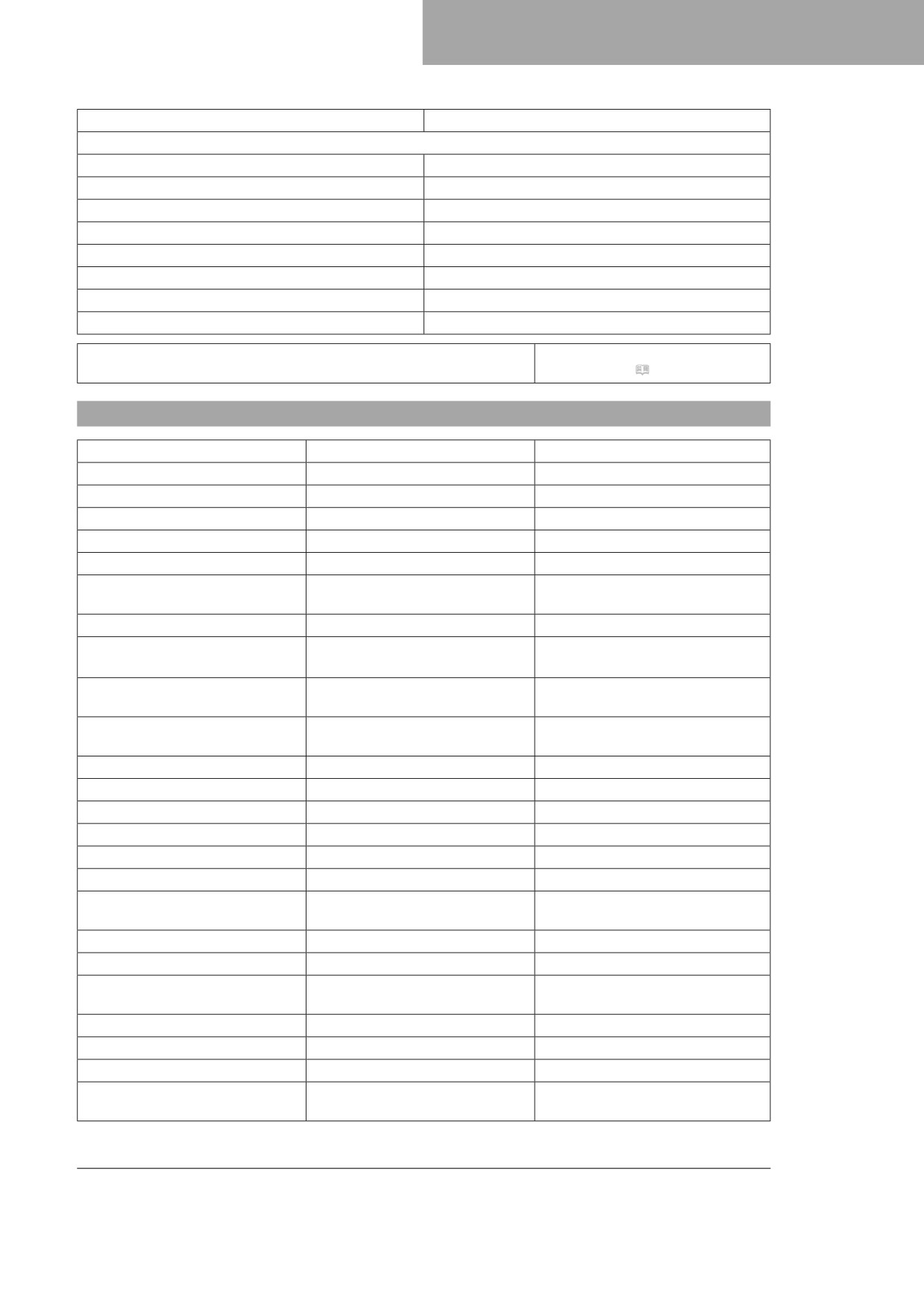
Spring preload
8 mm (0.31 in)
Spring rate
Weight of rider: 65 … 75 kg (143 … 165 lb.)
39 N/mm (223 lb/in)
Weight of rider: 75 … 85 kg (165 … 187 lb.)
42 N/mm (240 lb/in)
Weight of rider: 85 … 95 kg (187 … 209 lb.)
45 N/mm (257 lb/in)
Spring length
240 mm (9.45 in)
Gas pressure
10 bar (145 psi)
Static sag
35 mm (1.38 in)
Riding sag
105 mm (4.13 in)
Fitted length
456.3 mm (17.965 in)
Shock absorber oil
Shock absorber fluid (SAE
2.5)
(50180751S1) ( p. 141)
22.9
Chassis tightening torques
Fitting, start button
EJOT PT®K50x18
2 Nm (1.5 lbf ft)
Fitting, stop button
EJOT PT®K50x18
2 Nm (1.5 lbf ft)
Screw, air filter box cover
EJOT PT® K60x20-Z
5 Nm (3.7 lbf ft)
Screw, air filter box on frame
EJOT PT®K60x20-AL
5 Nm (3.7 lbf ft)
Screw, combination switch
EJOT PT® K50x18
2 Nm (1.5 lbf ft)
Screw, fuel pump on fuel tank
EJOT PT® K60x30-Z
2.5 Nm (1.84 lbf ft)
Screw, intake air temperature sen-
EJOT DELTA PT®K50x18 T20
0.7 Nm (0.52 lbf ft)
sor
Screw, seat fixing
EJOT EJOFORM PT® K60x23/18
2.5 Nm (1.84 lbf ft)
Screw, fixed grip
M4
5 Nm (3.7 lbf ft)
Loctite®243™
Screw, hose clip for cooling sys-
M4
2.4 Nm (1.77 lbf ft)
tem
Screw, throttle valve body hose
M4
2.8 Nm (2.07 lbf ft)
clamp
Spoke nipple, front wheel
M4.5
6 Nm (4.4 lbf ft)
Spoke nipple, rear wheel
M4.5
6 Nm (4.4 lbf ft)
Remaining nuts, chassis
M5
5 Nm (3.7 lbf ft)
Remaining screws, chassis
M5
5 Nm (3.7 lbf ft)
Screw, battery terminal
M5
2.5 Nm (1.84 lbf ft)
Screw, frame protector
M5
3 Nm (2.2 lbf ft)
Screw, shock absorber adjusting
M5
5 Nm (3.7 lbf ft)
ring
Screw, throttle valve body cover
M5
2.6 Nm (1.92 lbf ft)
Nut, cable on starter motor
M6
4 Nm (3 lbf ft)
Nut, throttle cable on throttle
M6
3 Nm (2.2 lbf ft)
valve body
Remaining nuts, chassis
M6
10 Nm (7.4 lbf ft)
Remaining screws, chassis
M6
10 Nm (7.4 lbf ft)
Screw, battery holding bracket
M6
6 Nm (4.4 lbf ft)
Screw, brake line guide on link
M6
4.5 Nm (3.32 lbf ft)
fork
137
22
TECHNICAL SPECIFICATIONS
Screw, chain guide on link fork at
M6x45
10 Nm (7.4 lbf ft)
the front
Screw, chain guide on link fork at
M6
10 Nm (7.4 lbf ft)
the front
Screw, chain guide on link fork at
M6x16
10 Nm (7.4 lbf ft)
the rear
Screw, chain guide on link fork at
M6
10 Nm (7.4 lbf ft)
the rear
Loctite®243™
Screw, chain sliding guard
M6
6 Nm (4.4 lbf ft)
Loctite®243™
Screw, fender
M6
12 Nm (8.9 lbf ft)
Screw, front brake disc
M6
14 Nm (10.3 lbf ft)
Loctite®243™
Screw, fuel tank spoiler on radia-
M6
6 Nm (4.4 lbf ft)
tor
Screw, ground wire on frame
M6
10 Nm (7.4 lbf ft)
Screw, hand lever
M6
5 Nm (3.7 lbf ft)
Screw, push rod ball joint on the
M6
10 Nm (7.4 lbf ft)
rear brake cylinder
Loctite®243™
Screw, rear brake disc
M6
14 Nm (10.3 lbf ft)
Loctite®243™
Screw, seat fixing
M6
8 Nm (5.9 lbf ft)
Screw, service hour counter
M6
5 Nm (3.7 lbf ft)
Screw, starter cable to starter
M6
6 Nm (4.4 lbf ft)
relay
Screw, throttle grip
M6
5 Nm (3.7 lbf ft)
Brake lever stop nut
M8
20 Nm (14.8 lbf ft)
Nut, rear sprocket screw
M8
35 Nm (25.8 lbf ft)
Loctite®2701™
Nut, rim lock
M8
12 Nm (8.9 lbf ft)
Remaining nuts, chassis
M8
25 Nm (18.4 lbf ft)
Remaining screws, chassis
M8
25 Nm (18.4 lbf ft)
Screw, bottom triple clamp
M8
12 Nm (8.9 lbf ft)
Screw, chain sliding piece
M8
15 Nm (11.1 lbf ft)
Screw, engine brace on engine
M8x20
25 Nm (18.4 lbf ft)
Loctite®243™
Screw, engine brace on frame
M8x15
25 Nm (18.4 lbf ft)
Loctite®2701™
Screw, engine sprocket cover
M8
15 Nm (11.1 lbf ft)
Screw, fork stub
M8
15 Nm (11.1 lbf ft)
Screw, front brake caliper
M8
25 Nm (18.4 lbf ft)
Loctite®243™
Screw, handlebar clamp
M8
20 Nm (14.8 lbf ft)
Screw, manifold on cylinder head
M8
15 Nm (11.1 lbf ft)
brace
Screw, subframe
M8
35 Nm (25.8 lbf ft)
Loctite®243™
Screw, subframe bottom
M8
30 Nm (22.1 lbf ft)
Loctite®2701™
138
TECHNICAL SPECIFICATIONS
22
Screw, top steering stem
M8
20 Nm (14.8 lbf ft)
Loctite®243™
Screw, top triple clamp
M8
17 Nm (12.5 lbf ft)
Engine carrying screw
M10
60 Nm (44.3 lbf ft)
Remaining nuts, chassis
M10
45 Nm (33.2 lbf ft)
Remaining screws, chassis
M10
45 Nm (33.2 lbf ft)
Screw, bottom shock absorber
M10
60 Nm (44.3 lbf ft)
Loctite®2701™
Screw, handlebar support
M10
40 Nm (29.5 lbf ft)
Loctite®243™
Screw, top shock absorber
M10
60 Nm (44.3 lbf ft)
Loctite®2701™
Nut, angle lever to link fork
M16x1.5
80 Nm (59 lbf ft)
Nut, fork pivot
M16x1.5
100 Nm (73.8 lbf ft)
Nut, frame on linkage lever
M16x1.5
80 Nm (59 lbf ft)
Nut, linkage lever on angle lever
M16x1.5
80 Nm (59 lbf ft)
Screw, front wheel spindle
M20x1.5
35 Nm (25.8 lbf ft)
Screw, top steering head
M20x1.5
12 Nm (8.9 lbf ft)
Nut, wheel spindle, rear
M22x1.5
80 Nm (59 lbf ft)
Screw-in fitting, cooling system
M24x1.5
7.5 Nm (5.53 lbf ft)
139
23
SUBSTANCES
Brake fluid DOT 4 / DOT 5.1
Standard/classification
- DOT
Guideline
- Use only brake fluid that complies with the specified standard (see specifications on the container) and that
exhibits the corresponding properties.
Recommended supplier
Castrol
- REACT PERFORMANCE DOT 4
MOTOREX®
- Brake Fluid DOT 5.1
Coolant
Guideline
- Only use high-grade, silicate-free coolant with corrosion inhibitor additive for aluminum motors. Low grade
and unsuitable antifreeze causes corrosion, deposits and frothing.
- Do not use pure water as only coolant is able to meet the requirements needed in terms of corrosion pro-
tection and lubrication properties.
- Only use coolant that complies with the requirements stated (see specifications on the container) and that
has the relevant properties.
Antifreeze protection to at least
−25 °C (−13 °F)
The mixture ratio must be adjusted to the necessary antifreeze protection. Use distilled water if the coolant
needs to be diluted.
The use of premixed coolant is recommended.
Observe the coolant manufacturer specifications for antifreeze protection, dilution and miscibility (compatibility)
with other coolants.
Recommended supplier
MOTOREX®
- COOLANT M3.0
Engine oil (SAE 10W/50)
Standard/classification
- JASO T903 MA2 ( p. 144)
- SAE ( p. 144) (SAE 10W/50)
Guideline
- Use only engine oils that comply with the specified standards (see specifications on the container) and that
possess the corresponding properties.
Fully synthetic engine oil
Recommended supplier
MOTOREX®
- Cross Power 4T
140
SUBSTANCES
23
Fork oil (SAE 4) (48601166S1)
Standard/classification
- SAE ( p. 144) (SAE 4)
Guideline
- Use only oils that comply with the specified standards (see specifications on the container) and that exhibit
the corresponding properties.
Shock absorber fluid (SAE 2.5) (50180751S1)
Standard/classification
- SAE ( p. 144) (SAE 2.5)
Guideline
- Use only oils that comply with the specified standards (see specifications on the container) and that exhibit
the corresponding properties.
Super unleaded (ROZ 95)
Standard/classification
- DIN EN 228 (ROZ 95)
Guideline
- Only use super unleaded fuel that matches or is equivalent to the specified standard.
- Fuel with an ethanol content of up to 10% (E10 fuel) is safe to use.
Info
Do not use fuel containing methanol (e.g., M15, M85, M100) or more than 10% ethanol (e.g., E15,
E25, E85, E100).
141
24
AUXILIARY SUBSTANCES
Air filter cleaner
Recommended supplier
MOTOREX®
- Racing Bio Dirt Remover
Chain cleaner
Recommended supplier
MOTOREX®
- Chain Clean
Fuel additive
Recommended supplier
MOTOREX®
- Fuel Stabilizer
High viscosity grease
Recommended supplier
SKF®
- LGHB 2
Long-life grease
Recommended supplier
MOTOREX®
- Bike Grease 2000
Motorcycle cleaner
Recommended supplier
MOTOREX®
- Moto Clean
Off-road chain spray
Recommended supplier
MOTOREX®
- Chainlube Offroad
Oil for foam air filter
Recommended supplier
MOTOREX®
- Racing Bio Liquid Power
Preserving materials for paints, metal and rubber
Recommended supplier
MOTOREX®
- Moto Protect
142
AUXILIARY SUBSTANCES
24
Silicone spray
Recommended supplier
MOTOREX®
- Silicone Spray
Special cleaner for glossy and matte paint finishes, metal and plastic surfaces
Recommended supplier
MOTOREX®
- Quick Cleaner
Special grease (00062010053)
Recommended supplier
Klüber Lubrication®
- Klüberfood NH1 34-401
Universal oil spray
Recommended supplier
MOTOREX®
- Joker 440 Synthetic
143
25
STANDARDS
JASO T903 MA2
Different technical development directions required a separate specification for motorcycles - the
JASO T903 MA2 standard.
Earlier, engine oils from the automobile industry were used for motorcycles because there was no separate
motorcycle specification.
Whereas long service intervals are demanded for automobile engines, the focus for motorcycle engines is on
high performance at high engine speeds.
In most motorcycle engines, the transmission and clutch are lubricated with the same oil.
The JASO T903 MA2 standard meets these special requirements.
SAE
The SAE viscosity classes were defined by the Society of Automotive Engineers and are used for classifying
oils according to their viscosity. The viscosity describes only one property of oil and says nothing about quality.
144
INDEX OF SPECIAL TERMS
26
-
Launch control
Vehicles electronics functions for achieving the best
possible acceleration from a standing position
OBD
On-board diagnosis
Vehicle system, which monitors the specified param-
eters of the vehicle electronics
-
Quickshifter
Function of the engine electronics for shifting up
without clutch actuation
TC
Traction Control
Auxiliary function of the motor control that reduces
engine torque with spinning rear wheel
145
27
LIST OF ABBREVIATIONS
Art. no.
Article number
ca.
circa
cf.
compare
e.g.
for example
etc.
et cetera
i.a.
inter alia
no.
number
poss.
possibly
146
LIST OF SYMBOLS
28
28.1
Yellow and orange symbols
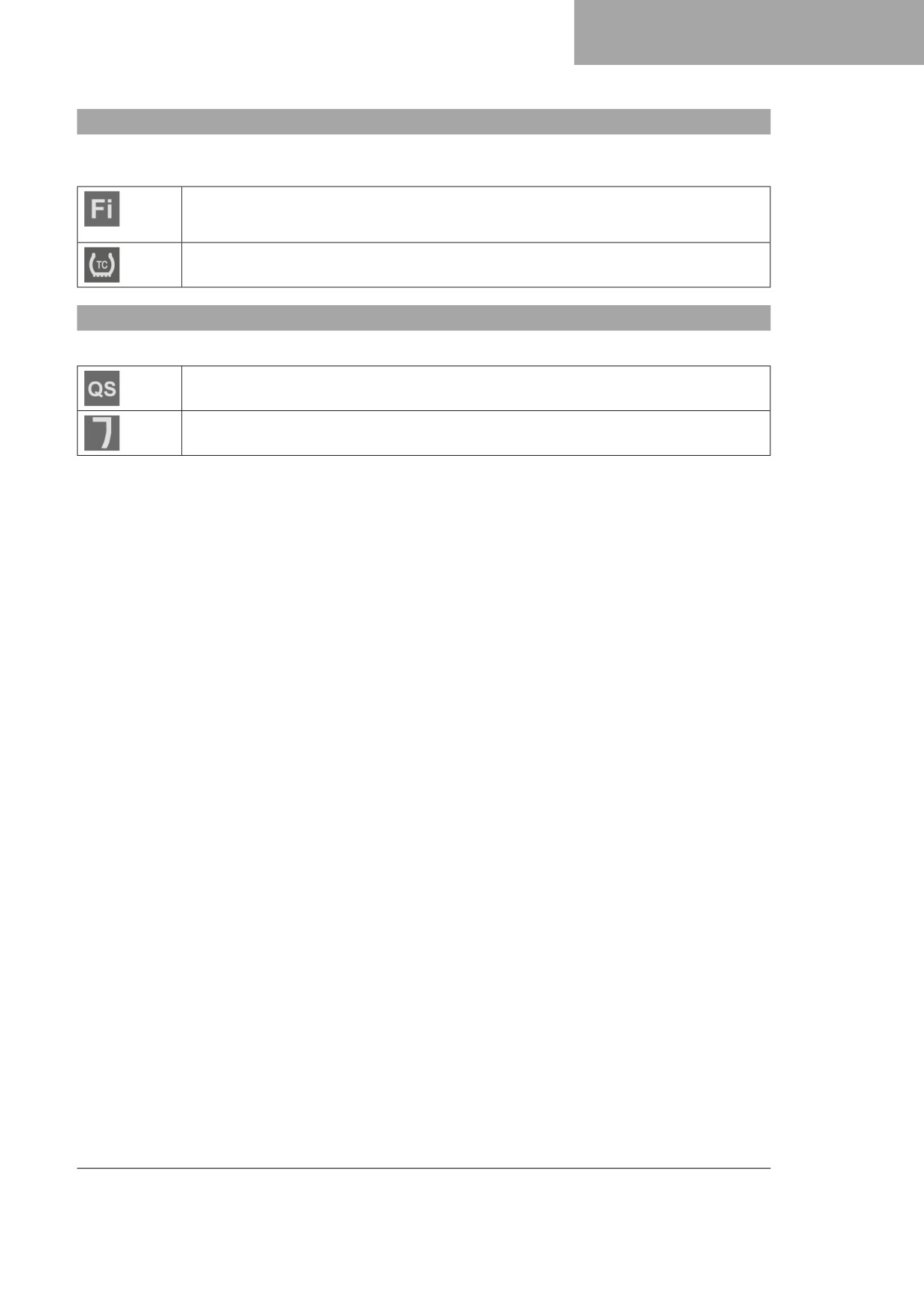
Yellow and orange symbols indicate an error condition that requires prompt intervention. Active driving aids are
also represented by yellow or orange symbols.
Malfunction indicator lamp lights up/flashes orange - The OBD has detected a malfunction
in the vehicle electronics. The malfunction indicator lamp also lights up if traction control is
activated and the speed limiter intervenes.
TC indicator lamp lights up orange - TC is enabled or is currently intervening. The TC indi-
cator lamp flashes if launch control is activated.
28.2
Green and blue symbols
Green and blue symbols reflect information.
QS indicator lamp lights up blue - The quickshifter is activated. The QS indicator lamp
flashes when the quickshifter is being programmed.
Indicator lamp B lights up green - ADVANCED mapping is activated.
147