HUSQVARNA FC 250. OWNER'S MANUAL (2024) - page 2
TUNING THE CHASSIS
10
10.10
Adjusting the spring preload of the shock absorber
Caution
Risk of injury Parts of the shock absorber will move around if the shock absorber is detached incor-
rectly.
The shock absorber is filled with highly compressed nitrogen.
- Please follow the description provided. (Your authorized Husqvarna Motorcycles workshop will be
glad to help.)
Info
Note the current adjustment before changing the spring preload - e.g. measure the spring length.
Preparatory work
- Remove the right side panel. ( p. 67)
- Remove the frame protector. ( p. 51)
- Remove main silencer. ( p. 68)
- Raise the motorcycle with a lift stand. ( p. 49)
- Remove the shock absorber.
(
p. 59)
– After removing the shock absorber, clean it thoroughly.
Main work
-
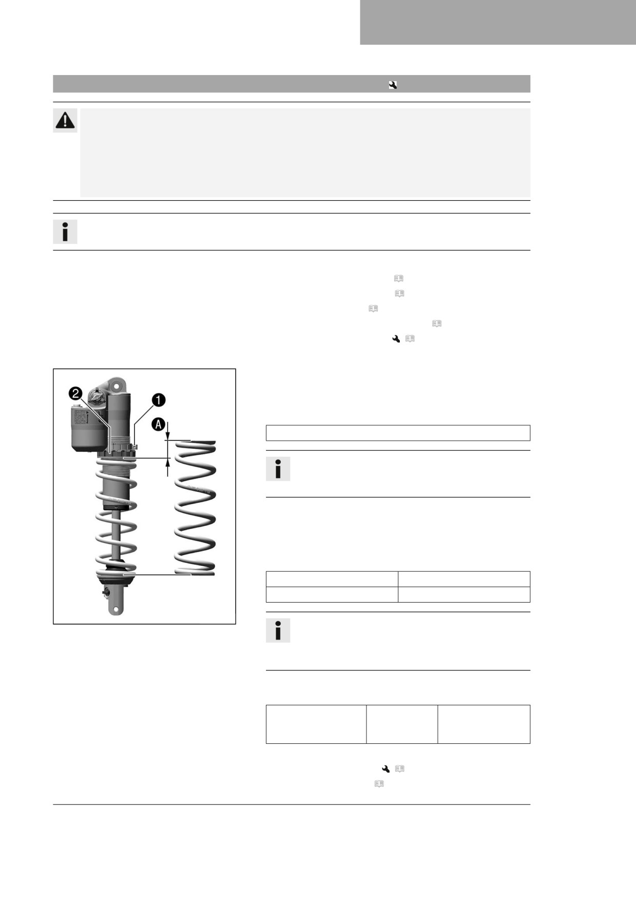
Loosen screw 1.
–
Turn adjusting ring 2 until the spring is no longer under ten-
sion.
Hook wrench (90129051000)
Info
If the spring cannot be fully released, the spring must
be removed to accurately measure the spring length.
-
Measure the total spring length while the spring is not under
tension.
-
Tension the spring by turning adjusting ring 2 to specified
dimension A.
Guideline
Spring preload (FC 250 EU)
8 mm (0.31 in)
Spring preload (FC 250 US)
8 mm (0.31 in)
F03627-10
Info
Depending on the static sag and/or the riding sag, it
may be necessary to increase or decrease the spring
preload.
-
Tighten bolt 1.
Guideline
Screw, shock
M5
5 Nm (3.7 lbf ft)
absorber adjusting
ring
Finishing work
- Install the shock absorber.
(
p. 60)
– Install the main silencer. ( p. 68)
41
10
TUNING THE CHASSIS
- Install the frame protector. ( p. 52)
- Install the right side panel. ( p. 67)
- Check the free travel of the foot brake lever. ( p. 88)
- Remove the motorcycle from the lift stand. ( p. 49)
10.11
Adjusting the riding sag
Preparatory work
- Remove the right side panel. ( p. 67)
- Remove the frame protector. ( p. 51)
- Remove main silencer. ( p. 68)
- Raise the motorcycle with a lift stand. ( p. 49)
- Remove the shock absorber.
(
p. 59)
– After removing the shock absorber, clean it thoroughly.
Main work
- Select and mount a suitable spring.
Guideline
Spring rate (FC 250 EU)
Weight of rider: 65 …
42 N/mm (240 lb/in)
75 kg (143 … 165 lb.)
Weight of rider: 75 …
45 N/mm (257 lb/in)
85 kg (165 … 187 lb.)
B00292-10
Weight of rider: 85 …
48 N/mm (274 lb/in)
95 kg (187 … 209 lb.)
Spring rate (FC 250 US)
Weight of rider: 65 …
39 N/mm (223 lb/in)
75 kg (143 … 165 lb.)
Weight of rider: 75 …
42 N/mm (240 lb/in)
85 kg (165 … 187 lb.)
Weight of rider: 85 …
45 N/mm (257 lb/in)
95 kg (187 … 209 lb.)
Info
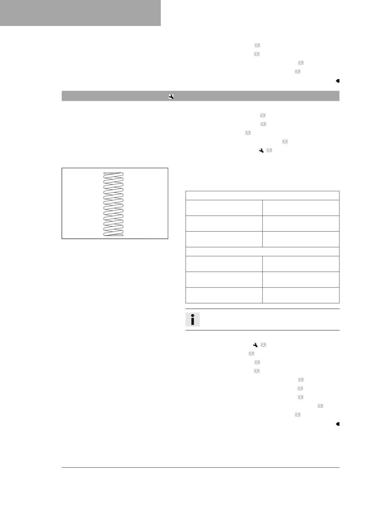
The spring rate is shown on the outside of the spring.
Finishing work
- Install the shock absorber.
(
p. 60)
– Install the main silencer. ( p. 68)
- Install the frame protector. ( p. 52)
- Install the right side panel. ( p. 67)
- Check the free travel of the foot brake lever. ( p. 88)
- Check the static sag of the shock absorber. ( p. 40)
- Check the riding sag of the shock absorber. ( p. 40)
- Adjust the rebound damping of the shock absorber. ( p. 38)
- Remove the motorcycle from the lift stand. ( p. 49)
42

TUNING THE CHASSIS
10
10.12
Checking the basic setting of the fork
Info
For various reasons, no exact riding sag can be determined for the fork.
- Smaller differences in the rider's weight can be compensated
for by the fork air pressure.
- However, if the fork frequently bottoms out (hard end stop on
compression), the fork air pressure must be increased, within
the specified values, to avoid damage to the fork and frame.
- If the fork feels unusually hard after extended periods of
operation, the fork legs need to be bled.
401000-01
10.13
Adjusting the fork air pressure
Warning
Danger of accidents Modifications to the suspension setting may seriously alter the handling charac-
teristic.
Modifications which are not coordinated with others to the suspension setting may cause a serious
deterioration in the handling characteristic and overload components.
- Only make adjustments within the recommended range.
- Ride slowly to start with after making adjustments to get the feel of the new handling characteristic.
Info
Check or adjust the air pressure under the same conditions at the earliest 5 minutes after switching off
the engine.
The air suspension is located in the left fork leg. The pressure and rebound damping is located in the
right fork leg.
Preparatory work
- Raise the motorcycle with a lift stand. ( p. 49)
Main work
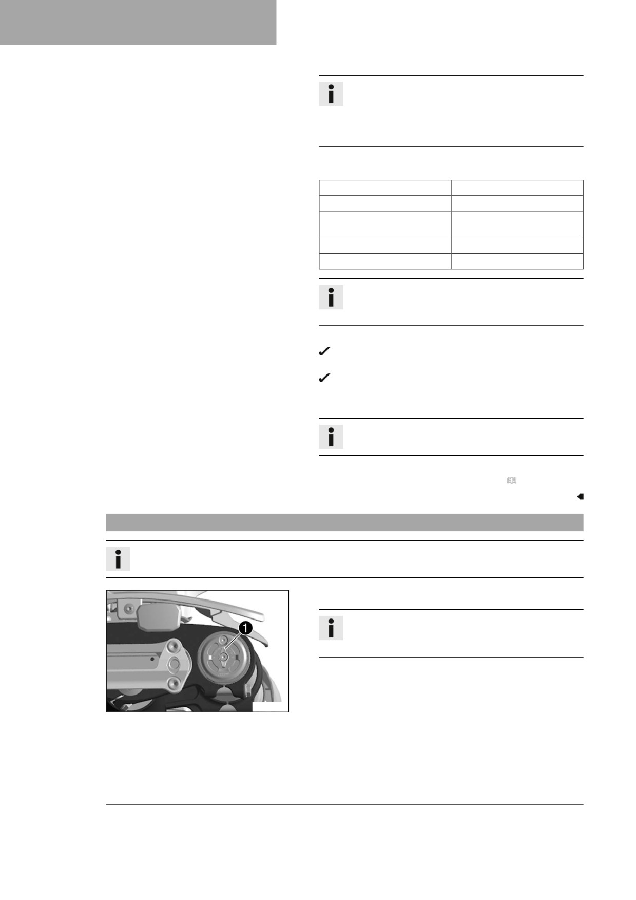
- Remove protection cap 1.
- Push together fork airpump 2 fully.
Fork airpump (79412966100)
Info
The fork airpump is included as part of the motorcy-
cle's accessory pack.
A01166-10
- Connect the fork airpump to the left fork leg.
The fork airpump indicator switches on automatically.
A little air escapes from the fork leg when connecting.
43
10
TUNING THE CHASSIS
Info
This is due to the volume of the hose and not due to a
defect in the fork airpump or the fork.
Observe the accompanying instructions for Husq-
varna Motorcycles technical accessories.
-
Adjust the air pressure as specified.
Guideline
Air pressure (FC 250 EU)
10.3 bar (149 psi)
Air pressure (FC 250 US)
10.5 bar (152 psi)
Gradual changing of the air
0.2 bar (3 psi)
pressure in steps of
Minimum air pressure
7 bar (102 psi)
Maximum air pressure
12 bar (174 psi)
Info
Never adjust the air pressure to a value outside the
stated range.
-
Disconnect the fork airpump from the left fork leg.
When disconnecting, excess pressure will escape from
the hose - the fork leg itself does not lose any air.
The fork airpump indicator switches off automatically
after 80 seconds.
-
Mount the protection cap.
Info
Only mount the protection cap by hand.
Finishing work
- Remove the motorcycle from the lift stand. ( p. 49)
10.14
Adjusting the compression damping of the fork
Info
The hydraulic compression damping determines the fork suspension behavior.
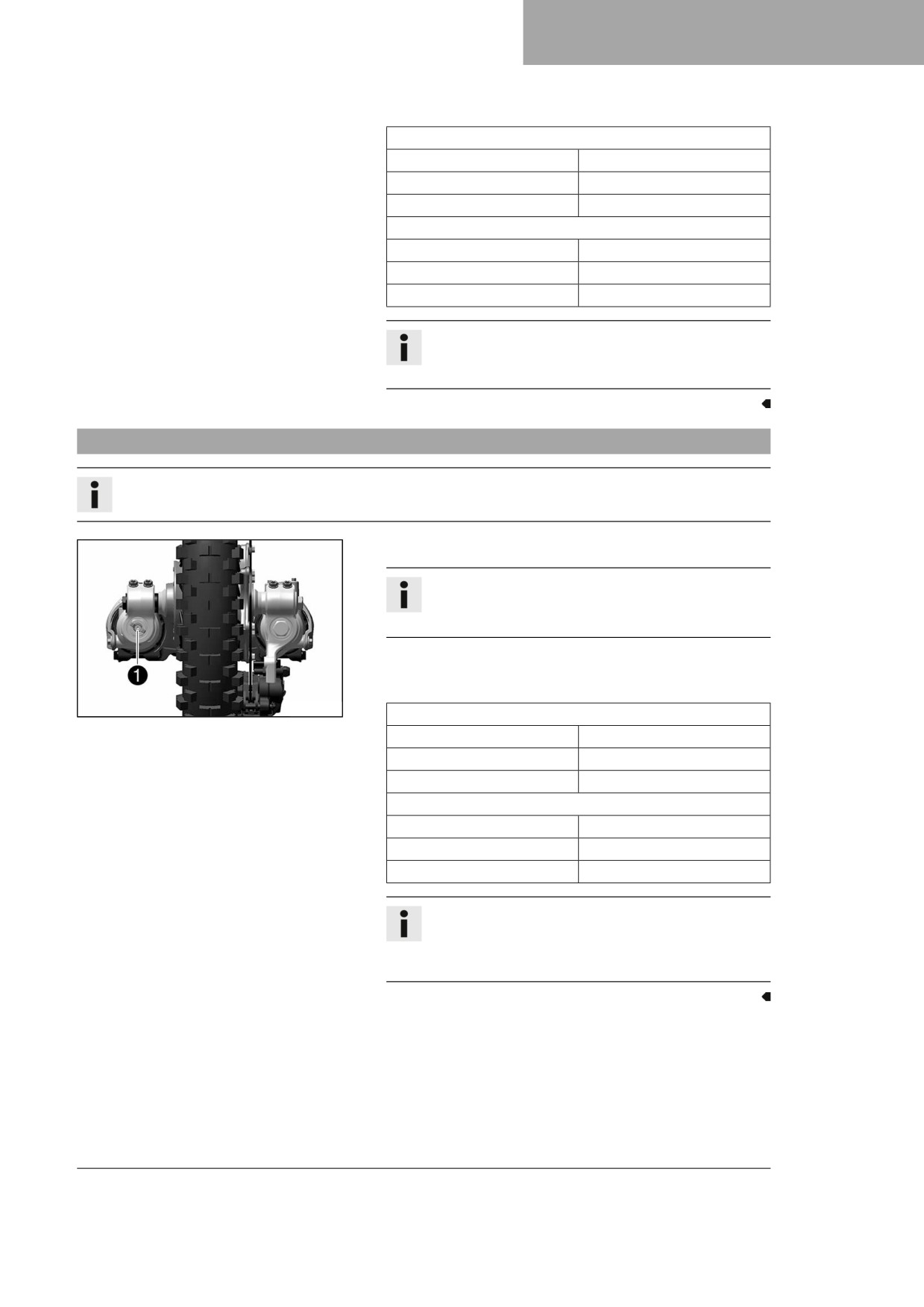
- Turn adjuster 1 clockwise all the way to the stop.
Info
Adjuster 1 is located at the upper end of the right
fork leg.
- Turn counterclockwise by the number of clicks correspond-
ing to the fork type.
A01167-10
44
TUNING THE CHASSIS
10
Guideline
Compression damping (FC 250 EU)
Comfort
17 clicks
Standard
12 clicks
Sport
7 clicks
Compression damping (FC 250 US)
Comfort
17 clicks
Standard
12 clicks
Sport
7 clicks
Info
Turn clockwise to increase damping; turn counter-
clockwise to reduce damping during compression.
10.15
Adjusting the rebound damping of the fork
Info
The hydraulic rebound damping determines the fork suspension behavior.
- Turn adjuster 1 clockwise all the way to the stop.
Info
Adjuster 1 is located at the lower end of the right
fork leg.
- Turn counterclockwise by the number of clicks correspond-
ing to the fork type.
Guideline
Z01370-10
Rebound damping (FC 250 EU)
Comfort
17 clicks
Standard
12 clicks
Sport
7 clicks
Rebound damping (FC 250 US)
Comfort
23 clicks
Standard
18 clicks
Sport
13 clicks
Info
Turn clockwise to increase the damping; turn
counterclockwise to reduce damping when the shock
absorber rebounds.
45
10
TUNING THE CHASSIS
10.16
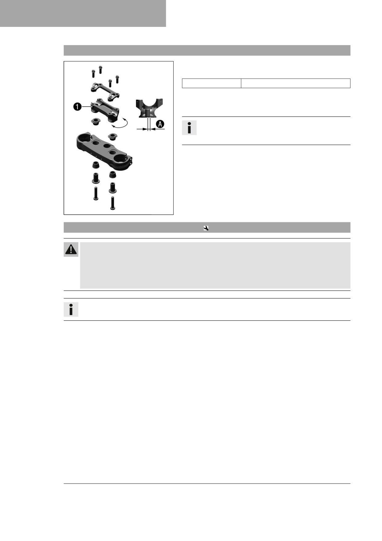
Handlebar position
The holes on the handlebar support 1 are placed at a distance
of A from the center.
Hole distance A
3.5 mm (0.138 in)
The handlebar can be mounted in 2 different positions. This
allows the handlebar to be mounted in the most comfortable
position for the rider.
Info
In addition, the handlebar can be mounted rigidly or on a
rubber bearing.
A01168-10
10.17
Adjusting the handlebar position
Warning
Danger of accidents A repaired handlebar poses a safety risk.
If the handlebar is bent or straightened, the material becomes fatigued. The handlebar may break as a
result.
- Change the handlebar if the handlebar is damaged or bent.
Info
The handlebar can be mounted rigidly or on a rubber bearing.
Preparatory work
- Take off the handlebar cushion.
46
TUNING THE CHASSIS
10
Main work
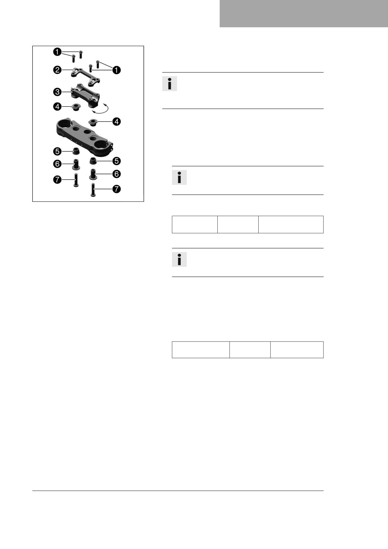
- Remove screws 1. Take off handlebar clamp 2. Take off
the handlebar and lay it to one side.
Info
Cover the components to protect them against dam-
age.
Do not kink the cables or lines.
- Remove screws 7 and bushing 6. Take off handlebar
support 3.
Adjusting the handlebar position with the handlebar clamp in
the rubber bearing
-
Position the rubber bushings 4 and 5.
–
Place the handlebar support in the required position.
Info
The handlebar support is longer and higher on one
side.
A01169-10
-
Mount and tighten the screws 7 with bushing 6.
Guideline
Screw, handle-
M10
40 Nm (29.5 lbf ft)
bar support
Loctite®243™
–
Position the handlebar.
Info
Make sure the cables and wiring are positioned
correctly.
-
Position handlebar clamp 2.
–
Mount screws 1, but do not tighten yet.
–
First bolt the handlebar clamp with screws 1 onto the
longer, higher side of the handlebar supports so that both
parts touch.
-
Tighten screws 1 evenly.
Guideline
Screw, handlebar
M8
20 Nm (14.8 lbf ft)
clamp
47
10
TUNING THE CHASSIS
Adjusting the handlebar position with the handlebar clamp
-
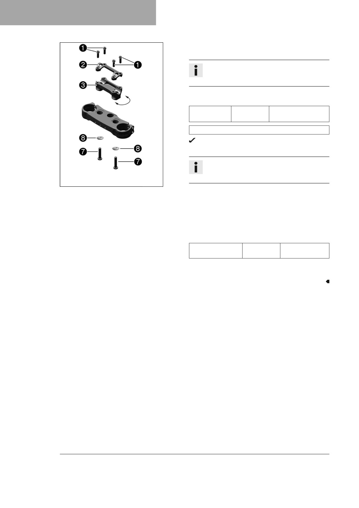
Place the handlebar support in the required position.
Info
The handlebar support is longer and higher on one
side.
-
Mount and tighten the screws 7 with the bushings 8.
Guideline
Screw, handle-
M10
40 Nm (29.5 lbf ft)
bar support
Loctite®243™
Rigid handlebar support bushing (A46001038010)
The conical side of bushing faces downwards.
-
Position the handlebar.
Info
Make sure the cables and wiring are positioned
correctly.
A01170-10
-
Position handlebar clamp 2.
–
Mount screws 1, but do not tighten yet.
–
First bolt the handlebar clamp with screws 1 onto the
longer, higher side of the handlebar supports so that both
parts touch.
-
Tighten screws 1 evenly.
Guideline
Screw, handlebar
M8
20 Nm (14.8 lbf ft)
clamp
Finishing work
- Mount the handlebar cushion.
48
SERVICE WORK ON THE CHASSIS
11
11.1
Raising the motorcycle with a lift stand
Note
Material damage The vehicle may be damaged by incorrect procedure when parking.
Significant damage may be caused if the vehicle rolls away or falls over.
The components for parking the vehicle are designed only for the weight of the vehicle.
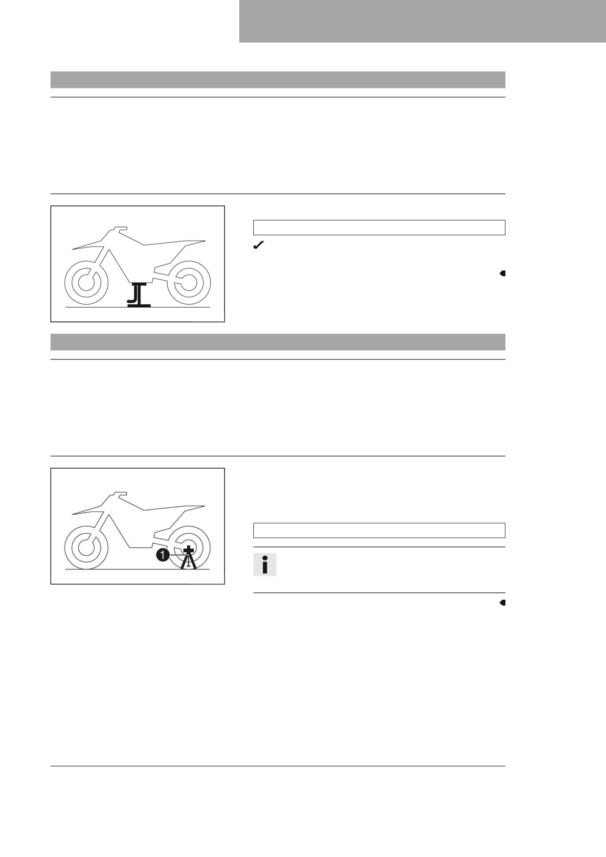
- Park the vehicle on a firm and level surface.
- Ensure that nobody sits on the vehicle when the vehicle is parked on a stand.
- Raise the motorcycle at the frame underneath the engine.
Lift stand (81329955100)
Neither wheel is in contact with the ground.
- Secure the motorcycle against falling over.
401942-01
11.2
Removing the motorcycle from the lift stand
Note
Material damage The vehicle may be damaged by incorrect procedure when parking.
Significant damage may be caused if the vehicle rolls away or falls over.
The components for parking the vehicle are designed only for the weight of the vehicle.
- Park the vehicle on a firm and level surface.
- Ensure that nobody sits on the vehicle when the vehicle is parked on a stand.
- Remove the motorcycle from the lift stand.
- Remove the lift stand.
- To park the motorcycle, insert plug-in stand 1 into the left
side of the wheel spindle.
Plug-in stand (A46029094000)
Info
The plug-in stand is included.
H02629-10
Remove the plug-in stand before riding.
49
11
SERVICE WORK ON THE CHASSIS
11.3
Bleeding the fork legs
Preparatory work
- Raise the motorcycle with a lift stand. ( p. 49)
Main work
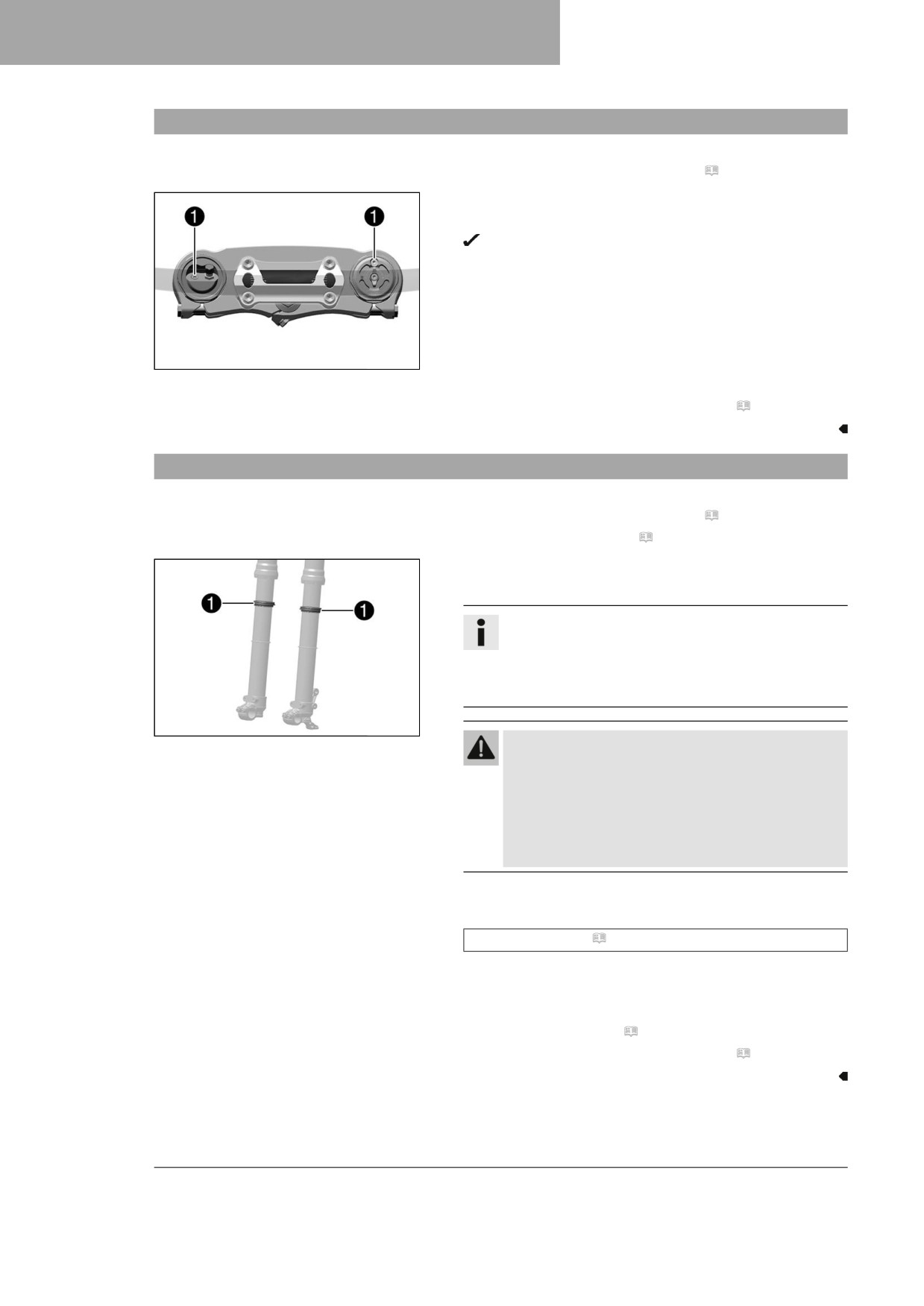
- Release bleeder screws 1.
Any excess pressure escapes from the interior of the
fork.
- Tighten the bleeder screws.
A01215-10
Finishing work
- Remove the motorcycle from the lift stand. ( p. 49)
11.4
Cleaning the dust boots of the fork legs
Preparatory work
- Raise the motorcycle with a lift stand. ( p. 49)
- Remove the fork protector. ( p. 51)
Main work
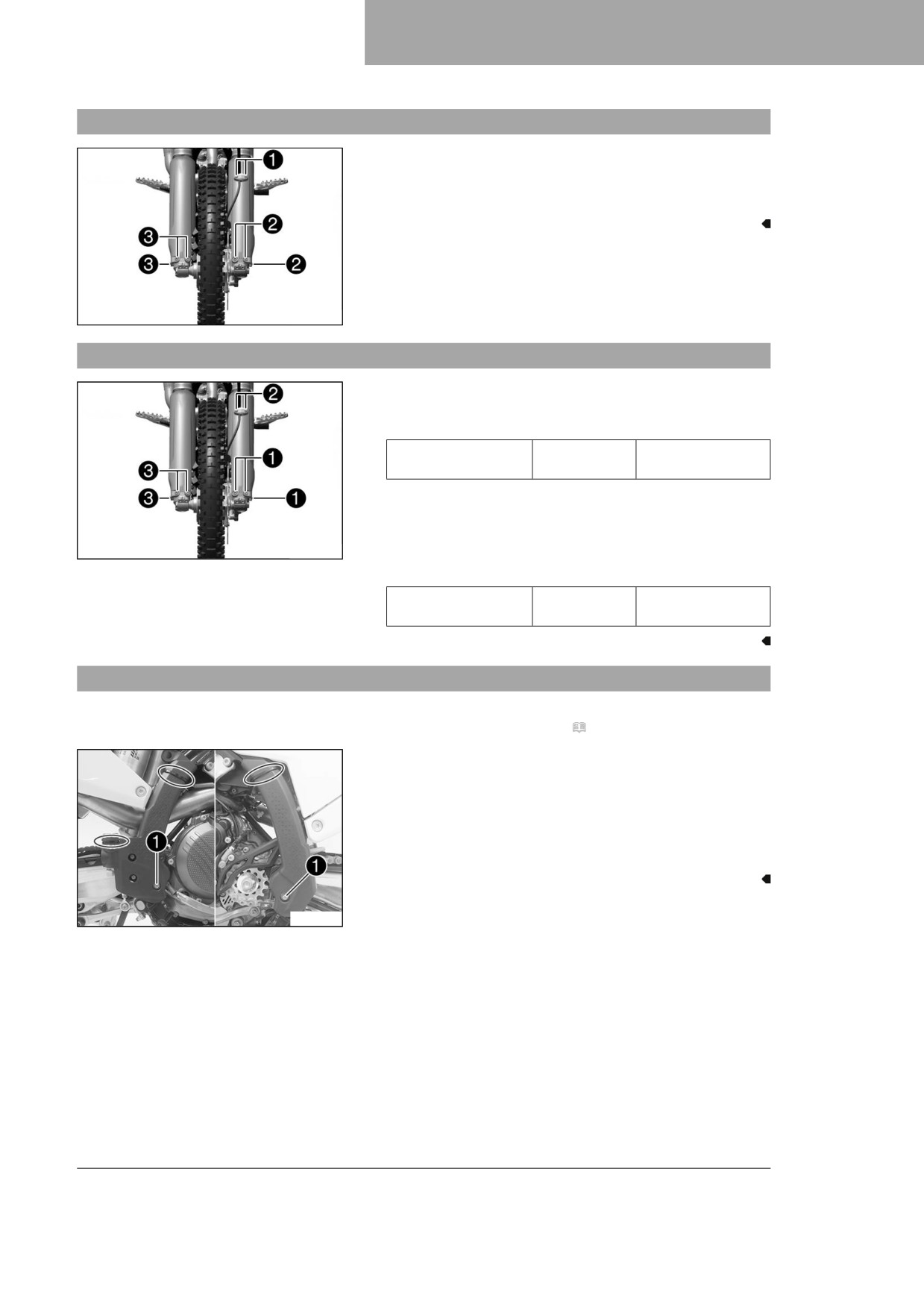
- Push dust boots 1 of both fork legs downward.
Info
The dust boots remove dust and coarse dirt parti-
cles from the inside fork tubes. Over time, dirt can
accumulate behind the dust boots. If this dirt is not
removed, the oil seals behind can start to leak.
F03666-10
Warning
Danger of accidents Oil or grease on the brake
discs reduces the braking effect.
- Always keep the brake discs free of oil and
grease.
- Clean the brake discs with brake cleaner when
necessary.
- Clean and oil the dust boots and inner fork tubes of both fork
legs.
Universal oil spray ( p. 143)
- Press the dust boots back into their installation position.
- Remove excess oil.
Finishing work
- Install the fork protector. ( p. 51)
- Remove the motorcycle from the lift stand. ( p. 49)
50
SERVICE WORK ON THE CHASSIS
11
11.5
Removing the fork protector
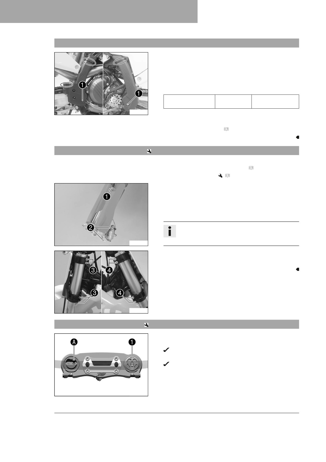
- Remove screws 1 and take off the clamp.
- Remove screws 2 and take off the left fork protector.
- Remove screws 3 and take off the right fork protector.
A01213-10
11.6
Installing the fork protector
- Position the fork protector on left fork leg. Mount and tighten
screws 1.
Guideline
Remaining screws,
M6
10 Nm (7.4 lbf ft)
chassis
- Position the brake line and the clamp. Mount and tighten
screws 2.
- Position the fork protector on the right fork leg. Mount and
A01213-11
tighten screws 3.
Guideline
Remaining screws,
M6
10 Nm (7.4 lbf ft)
chassis
11.7
Removing the frame protector
Preparatory work
- Remove the right side panel. ( p. 67)
Main work
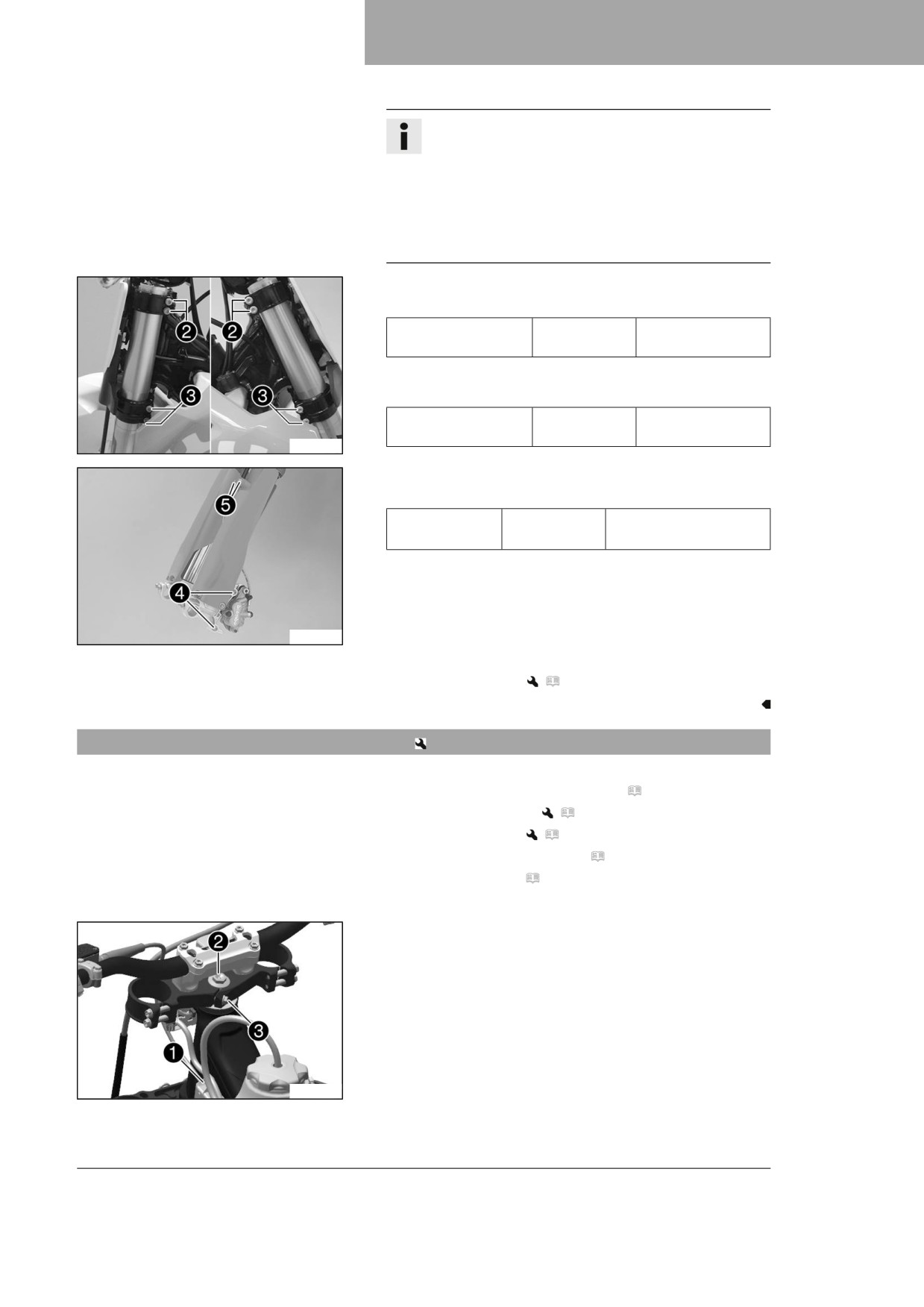
- Remove the cable ties.
- Remove screws 1 with the bushings.
- Take off the left frame protector.
- Push the right frame protector to the front and take off at the
bottom.
T04408-10
51
11
SERVICE WORK ON THE CHASSIS
11.8
Installing the frame protector
Main work
- Position the left frame protector.
- Insert the right frame protector from below and push it to the
rear.
- Mount screws 1 with the bushings and tighten.
Guideline
Screw, frame pro-
M5
3 Nm (2.2 lbf ft)
tector
T04408-10
- Secure the frame protector with cable ties.
Finishing work
- Install the right side panel. ( p. 67)
11.9
Removing the fork legs
Preparatory work
- Raise the motorcycle with a lift stand. ( p. 49)
- Remove the front wheel.
(
p. 95)
Main work
- Remove screws 1 and take off the clamp.
- Remove screws 2 and take off the brake caliper.
- Allow the brake caliper and brake line to hang loosely to the
side.
Info
Do not actuate the hand brake lever when the front
wheel is removed.
A01067-10
- Loosen screws 3. Remove the left fork leg.
- Loosen screws 4. Remove the right fork leg.
A01189-10
11.10
Installing the fork legs
Main work
- Position the fork legs.
Air bleeder screw 1 of the right fork leg is positioned to
the front.
Valve A of the left fork leg faces the front.
F03665-11
52
SERVICE WORK ON THE CHASSIS
11
Info
Grooves are milled into the side of the upper end of
the fork legs. The second milled groove (from the top)
must be flush with the upper edge of the upper triple
clamp.
The air suspension is located in the left fork leg. The
pressure and rebound damping is located in the right
fork leg.
-
Tighten screws 2.
Guideline
Screw, top triple
M8
17 Nm (12.5 lbf ft)
clamp
-
Tighten screws 3.
Guideline
Screw, bottom triple
M8
12 Nm (8.9 lbf ft)
clamp
A01189-11
-
Position the brake caliper. Mount and tighten screws 4.
Guideline
Screw, front
M8
25 Nm (18.4 lbf ft)
brake caliper
Loctite®243™
–
Position the brake line and the clamp. Mount and tighten
screws 5.
A01067-11
Finishing work
- Install the front wheel.
(
p. 96)
11.11
Removing the lower triple clamp
Preparatory work
- Raise the motorcycle with a lift stand. ( p. 49)
- Remove the front wheel.
(
p. 95)
– Remove the fork legs.
(
p. 52)
– Remove the start number plate. ( p. 58)
- Remove front fender. ( p. 58)
- Take off the handlebar cushion.
Main work
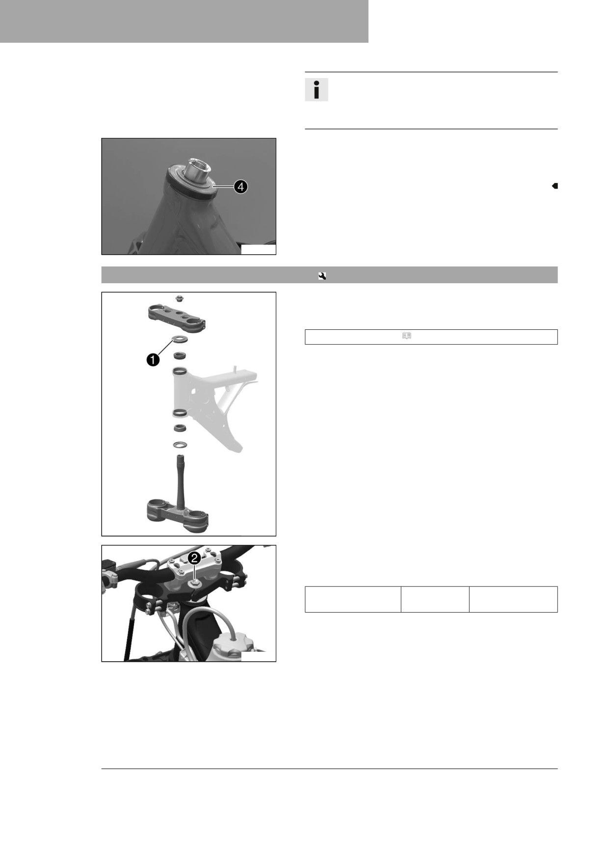
- Remove screw 1. Detach the wiring harness.
- Remove screw 2.
- Remove screw 3.
- Take off the upper triple clamp and handlebar and set it
aside.
A01190-10
53
11
SERVICE WORK ON THE CHASSIS
Info
Cover the components to protect them against dam-
age.
Do not kink the cables and lines.
- Remove the steering head seal 4.
- Remove the lower triple clamp and steering stem.
- Remove the upper steering head bearing.
A01070-10
11.12
Installing the lower triple clamp
Main work
- Clean the bearing and sealing elements, check for damage,
and grease.
High viscosity grease ( p. 142)
- Insert the lower triple clamp with the steering stem. Mount
upper steering head bearing.
- Push on the steering head seal 1.
A01192-10
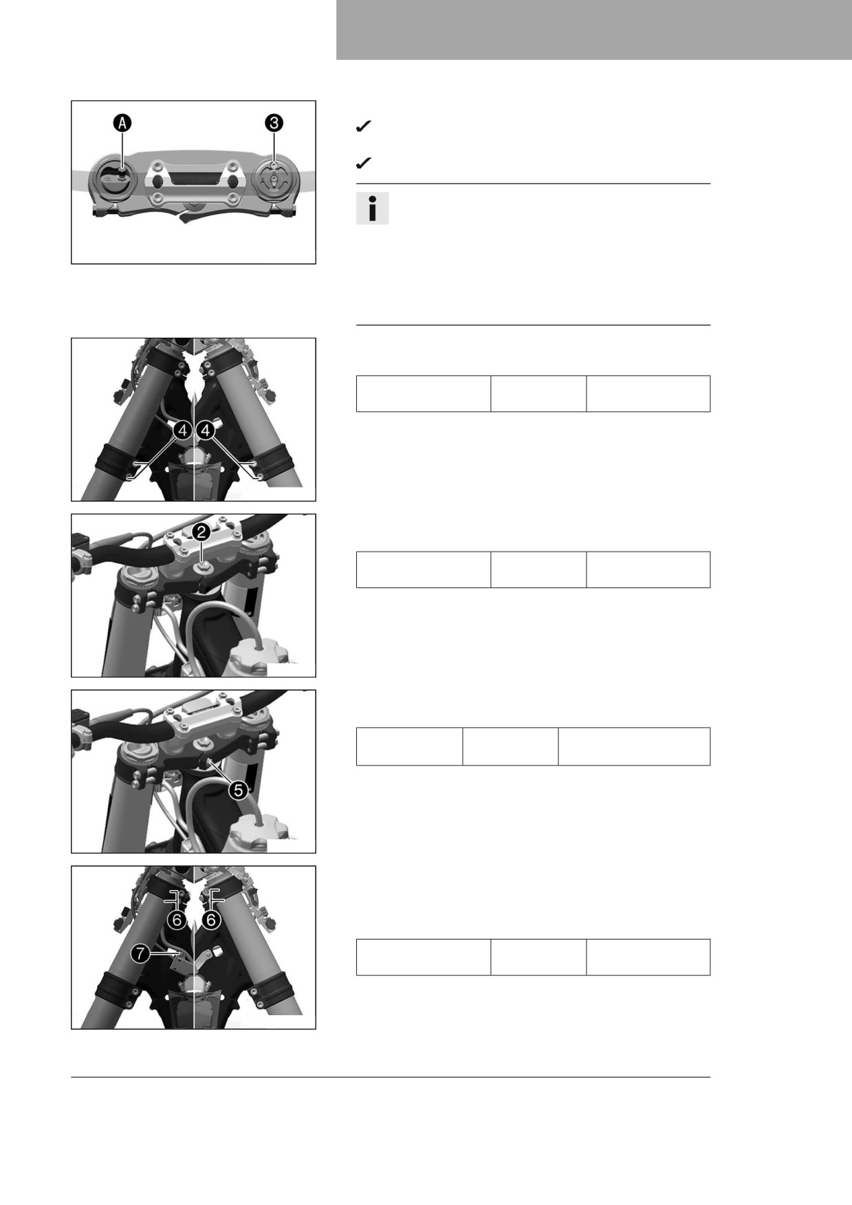
- Position the upper triple clamp and handlebar.
- Mount screw 2, but do not tighten it yet.
Guideline
Screw, top steering
M20x1.5
12 Nm (8.9 lbf ft)
head
A01190-11
54
SERVICE WORK ON THE CHASSIS
11
– Position the fork legs.
Air bleeder screw 3 of the right fork leg is positioned to
the front.
Valve A of the left fork leg faces the front.
Info
Grooves are milled into the side of the upper end of
the fork legs. The second milled groove (from the top)
must be flush with the upper edge of the upper triple
F03764-10
clamp.
The air suspension is located in the left fork leg. The
pressure and rebound damping is located in the right
fork leg.
- Tighten screws 4.
Guideline
Screw, bottom triple
M8
12 Nm (8.9 lbf ft)
clamp
A01198-10
- Tighten screw 2.
Guideline
Screw, top steering
M20x1.5
12 Nm (8.9 lbf ft)
head
A01191-11
- Mount and tighten screw 5.
Guideline
Screw, top
M8
20 Nm (14.8 lbf ft)
steering stem
Loctite®243™
A01191-10
- Using a plastic hammer, tap lightly on the upper triple clamp
to avoid stresses.
- Tighten screws 6.
Guideline
Screw, top triple
M8
17 Nm (12.5 lbf ft)
clamp
- Secure the wiring harness with cable holder on the left.
Mount and tighten screw 7.
A01198-11
55
11
SERVICE WORK ON THE CHASSIS
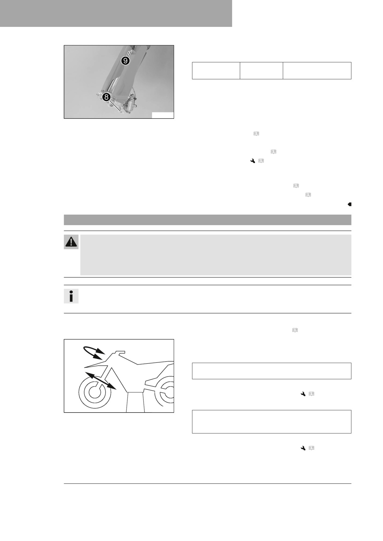
- Position the brake caliper. Mount and tighten screws 8.
Guideline
Screw, front
M8
25 Nm (18.4 lbf ft)
brake caliper
Loctite®243™
– Position the brake line and the clamp. Mount and tighten
screws 9.
A01067-12
Finishing work
- Install the front fender. ( p. 59)
- Mount the handlebar cushion.
- Install the start number plate. ( p. 58)
- Install the front wheel.
(
p. 96)
– Check that the wiring harness, throttle cables, and brake and
clutch lines can move freely and are routed correctly.
- Check the steering head bearing play. ( p. 56)
- Remove the motorcycle from the lift stand. ( p. 49)
11.13
Checking the steering head bearing play
Warning
Danger of accidents Incorrect steering head bearing play impairs the handling characteristic and
damages components.
- Correct incorrect steering head bearing play immediately. (Your authorized Husqvarna Motorcycles
workshop will be glad to help.)
Info
If the vehicle is operated for a lengthy period with play in the steering head bearing, the bearings and the
bearing seats in the frame can become damaged over time.
Preparatory work
- Raise the motorcycle with a lift stand. ( p. 49)
Main work
- Move the handlebar to the straight-ahead position. Move the
fork legs to and fro in the direction of travel.
Play should not be detectable on the steering head bear-
ing.
» If there is detectable play:
- Adjust steering head bearing play.
(
p. 57)
– Move the handlebar to and fro over the entire steering range.
H01167-01
It must be possible to move the handlebar easily over the
entire steering range. There should be no detectable detent
positions.
» If detent positions are detected:
- Adjust steering head bearing play.
(
p. 57)
– Check the steering head bearing and adjust if neces-
sary.
56
SERVICE WORK ON THE CHASSIS
11
Finishing work
- Remove the motorcycle from the lift stand. ( p. 49)
11.14
Adjusting steering head bearing play
Preparatory work
- Raise the motorcycle with a lift stand. ( p. 49)
- Remove the handlebar cushion.
Main work
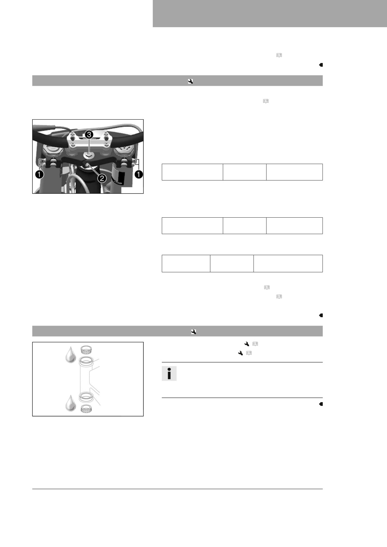
- Loosen screws 1.
- Remove screw 2.
- Loosen and retighten screw 3.
Guideline
Screw, top steering
M20x1.5
12 Nm (8.9 lbf ft)
head
- Using a plastic hammer, tap lightly on the upper triple clamp
A10214-10
to avoid stresses.
- Tighten screws 1.
Guideline
Screw, top triple
M8
17 Nm (12.5 lbf ft)
clamp
- Mount and tighten screw 2.
Guideline
Screw, top
M8
20 Nm (14.8 lbf ft)
steering stem
Loctite®243™
Finishing work
- Check the steering head bearing play. ( p. 56)
- Remove the motorcycle from the lift stand. ( p. 49)
- Mount the handlebar cushion.
11.15
Lubricating the steering head bearing
- Remove the lower triple clamp.
(
p. 53)
– Install the lower triple clamp.
(
p. 54)
Info
The steering head bearing is cleaned and lubricated
in the course of removal and installation of the lower
triple clamp.
H02387-01
57
11
SERVICE WORK ON THE CHASSIS
11.16
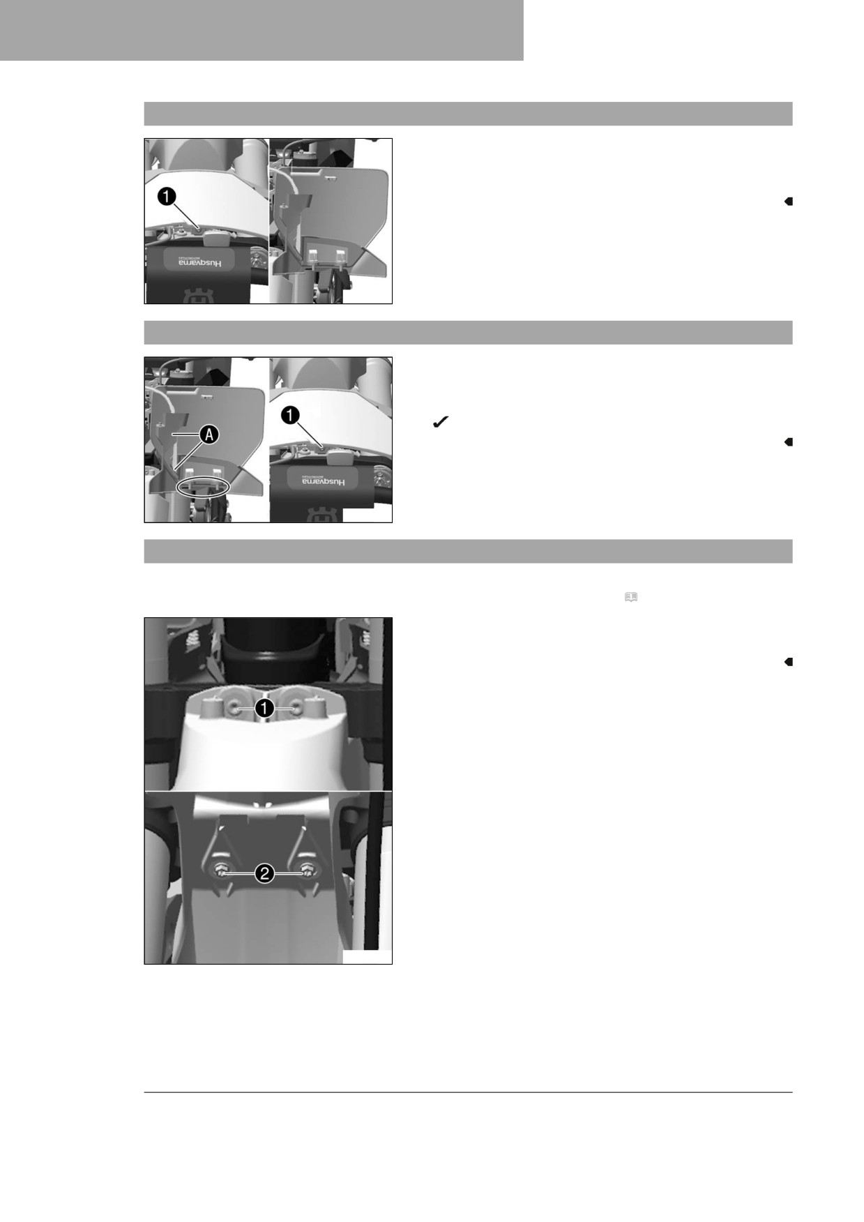
Removing the start number plate
- Remove screw 1.
- Unhook the start number plate from the brake line and
remove it.
A01216-10
11.17
Installing the start number plate
- Position the brake line in holders A on the start number
plate.
- Position the start number plate. Mount and tighten screw 1.
The holding lugs engage in the fender.
A01216-11
11.18
Removing front fender
Preparatory work
- Remove the start number plate. ( p. 58)
Main work
- Remove screws 1 and 2. Take off the front fender.
A01174-10
58
SERVICE WORK ON THE CHASSIS
11
11.19
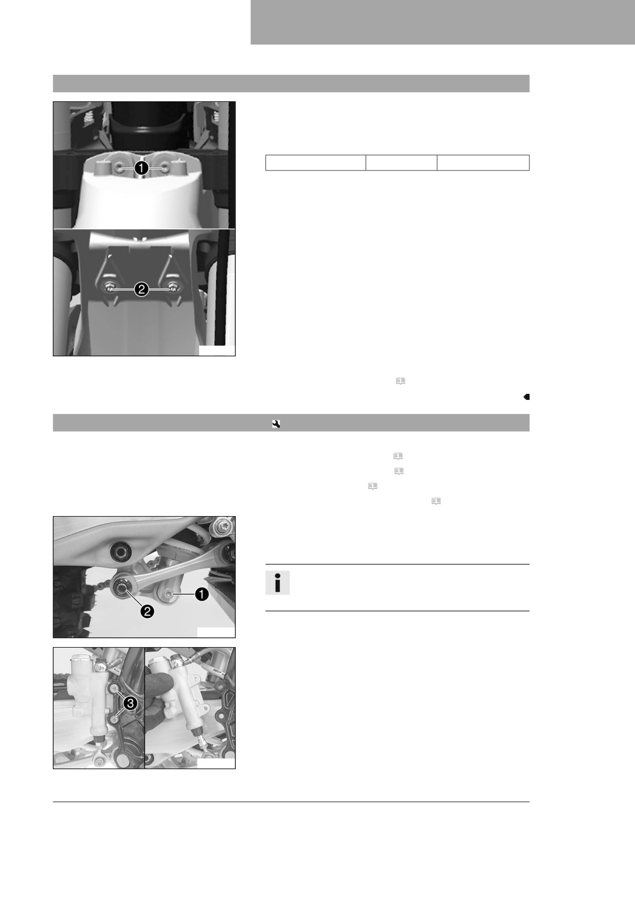
Installing the front fender
Main work
- Position the front fender. Mount and tighten screws 1
and 2.
Guideline
Screw, fender
M6
12 Nm (8.9 lbf ft)
A01174-10
Finishing work
- Install the start number plate. ( p. 58)
11.20
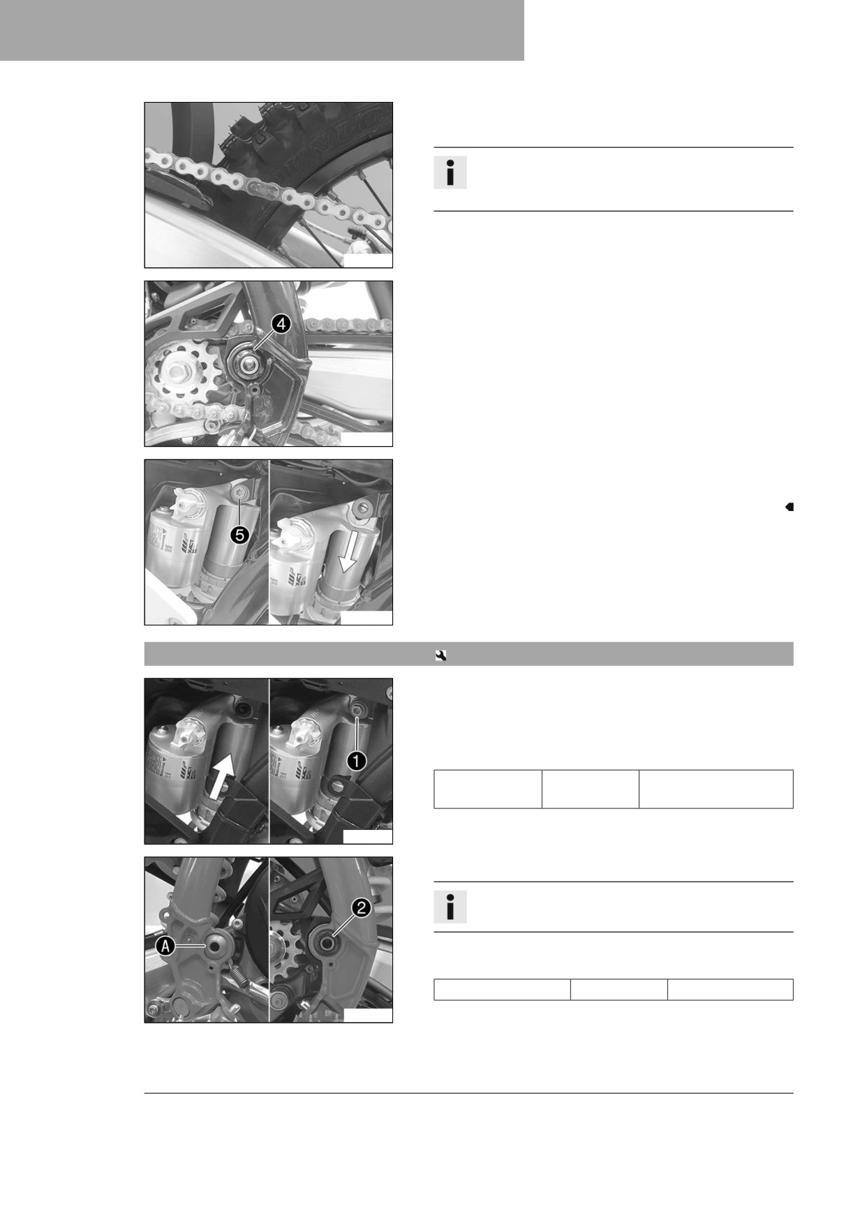
Removing the shock absorber
Preparatory work
- Remove the right side panel. ( p. 67)
- Remove the frame protector. ( p. 51)
- Remove main silencer. ( p. 68)
- Raise the motorcycle with a lift stand. ( p. 49)
Main work
- Remove screw 1.
- Remove fitting 2.
Info
Raise the swingarm slightly to be able to remove the
screws more easily.
W00036-10
- Remove screws 3.
- Pull rear brake cylinder off of the push rod.
W00051-10
59
11
SERVICE WORK ON THE CHASSIS
- Remove the connecting link of the chain.
- Take off the chain.
Info
Cover the components to protect them against dam-
age.
F03702-01
- Remove nut 4 and the swingarm pivot.
- Push the link fork back and secure it against falling over.
W00053-10
- Hold the shock absorber and remove screw 5.
- Remove the shock absorber carefully at the bottom.
W00055-10
11.21
Installing the shock absorber
Main work
- Carefully position the shock absorber into the vehicle from
the bottom.
- Mount and tighten screw 1.
Guideline
Screw, top
M10
60 Nm (44.3 lbf ft)
shock absorber
Loctite®2701™
A01101-10
- Position the link fork and mount the swingarm pivot.
Info
Pay attention to flat area A.
- Mount and tighten nut 2.
Guideline
Nut, fork pivot
M16x1.5
100 Nm (73.8 lbf ft)
F03705-10
60
SERVICE WORK ON THE CHASSIS
11
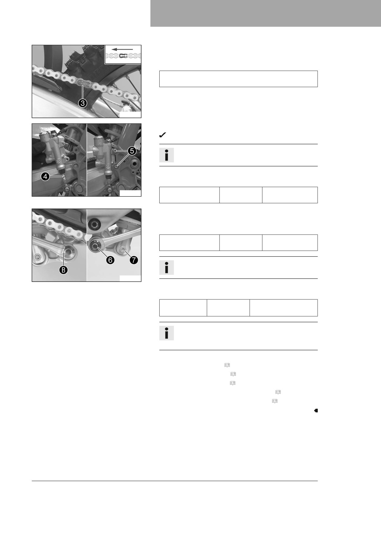
– Mount the chain.
- Connect the chain with connecting link 3.
Guideline
The closed side of the chain joint lock must face in the
direction of travel.
F03702-12
-
Position the rear brake cylinder.
Push rod 4 engages in the brake cylinder.
Info
Ensure that the dust boot is correctly seated.
-
Mount and tighten screws 5.
Guideline
F03706-10
Remaining screws,
M6
10 Nm (7.4 lbf ft)
chassis
-
Position the angle lever and linkage lever.
–
Mount and tighten fitting 6.
Guideline
Nut, linkage lever on
M16x1.5
80 Nm (59 lbf ft)
angle lever
Info
Pay attention to flat area B.
F03704-10
-
Mount and tighten screw 7.
Guideline
Screw, bottom
M10
60 Nm (44.3 lbf ft)
shock absorber
Loctite®2701™
Info
Raise the link fork slightly to be able to mount the
screw more easily.
Finishing work
- Install the main silencer. ( p. 68)
- Install the frame protector. ( p. 52)
- Install the right side panel. ( p. 67)
- Check the free travel of the foot brake lever. ( p. 88)
- Remove the motorcycle from the lift stand. ( p. 49)
61
11
SERVICE WORK ON THE CHASSIS
11.22
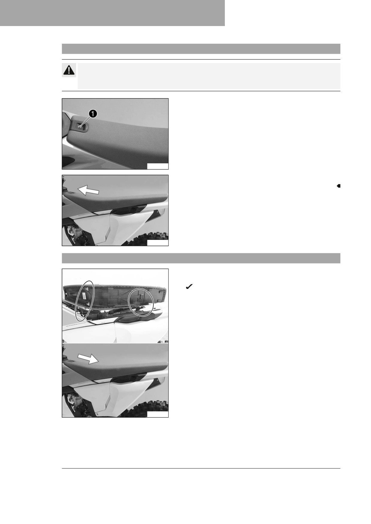
Removing the seat
Caution
Danger of burns The voltage regulator gets very hot when the vehicle is operated.
- Allow the voltage regulator to cool down before performing any work.
- Remove screw 1.
A01193-10
- Raise seat, pull it toward the fuel tank and take it off.
A01194-10
11.23
Mounting the seat
- Attach the seat to the collar bushings at the front and simul-
taneously push it back.
The holding lugs engage in the recesses at the back.
- Make sure the seat is latched in place correctly.
A01197-10
62
SERVICE WORK ON THE CHASSIS
11
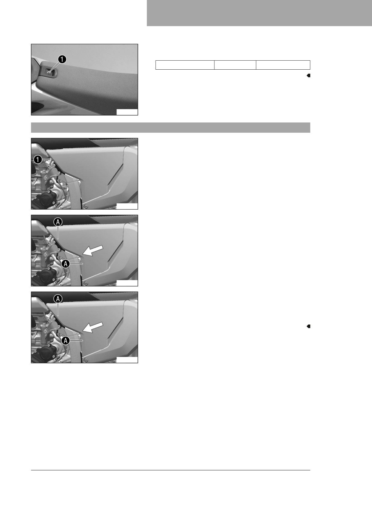
– Mount and tighten screw 1.
Guideline
Screw, seat fixing
M6
8 Nm (5.9 lbf ft)
A01193-10
11.24
Removing the air filter box cover
Condition
The air filter box cover is secured.
- Remove screw 1.
A01177-10
- Pull off the air filter box cover in area A and push it side-
ways and forward. Take off the air filter box cover.
A01177-11
Condition
The air filter box cover is not secured.
- Pull off the air filter box cover in area A and push it side-
ways and forward. Take off the air filter box cover.
A01177-11
63

11
SERVICE WORK ON THE CHASSIS
11.25
Installing the air filter box cover
Condition
The air filter box cover is secured.
- Insert the air filter box cover in area A and clip it into
area B.
Info
An air filter box cover with openings for greater
airflow and a more direct response is included.
A01178-10
- Mount and tighten screw 1.
Guideline
Screw, air filter box
EJOT PT®
5 Nm (3.7 lbf ft)
cover
K60x20-Z
A01177-10
Condition
The air filter box cover is not secured.
- Insert the air filter box cover in area A and clip it into
area B.
Info
An air filter box cover with openings for greater
airflow and a more direct response is included.
A01178-10
64
SERVICE WORK ON THE CHASSIS
11
11.26
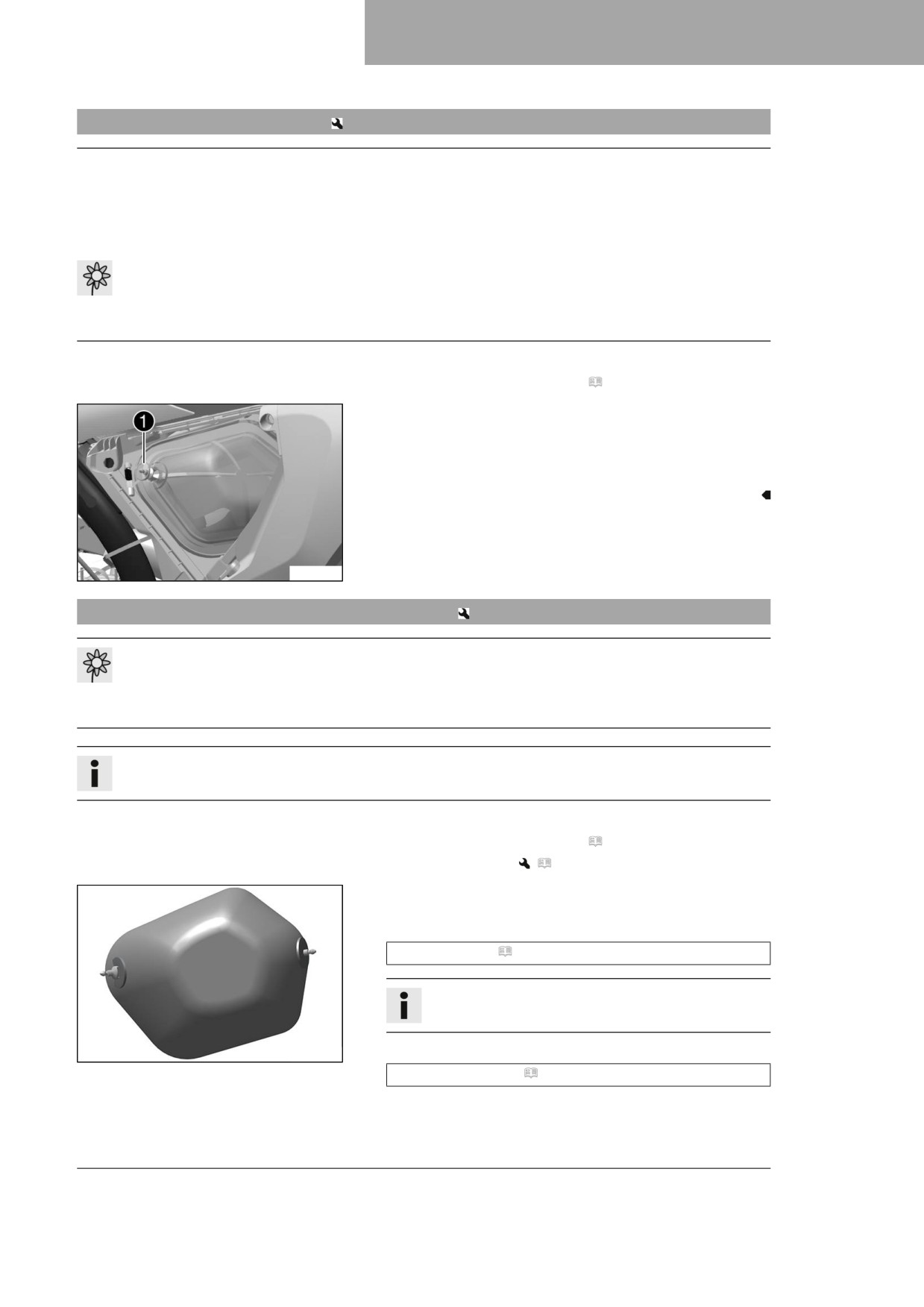
Removing the air filter
Note
Engine damage Unfiltered intake air has a negative effect on the service life of the engine.
Dust and dirt will enter the engine without an air filter.
- Only operate the vehicle if it is equipped with an air filter.
Note
Environmental hazard Hazardous substances cause environmental damage.
- Dispose of oils, grease, filters, fuel, cleaning agents, brake fluid, etc., correctly and in compliance
with the applicable regulations.
Preparatory work
- Remove the air filter box cover. ( p. 63)
Main work
- Detach retaining tab 1.
- Remove air filter with air filter support.
- Remove air filter from air filter support.
A01179-10
11.27
Cleaning the air filter and air filter box
Note
Environmental hazard Hazardous substances cause environmental damage.
- Dispose of oils, grease, filters, fuel, cleaning agents, brake fluid, etc., correctly and in compliance
with the applicable regulations.
Info
Do not clean the air filter with fuel or petroleum since these substances attack the foam.
Preparatory work
- Remove the air filter box cover. ( p. 63)
- Remove the air filter.
(
p. 65)
Main work
- Wash the air filter thoroughly in special cleaning liquid and
allow it to dry properly.
Air filter cleaner ( p. 142)
Info
Only press the air filter to dry it, never wring it out.
- Oil the dry air filter with a high-grade air filter oil.
F03685-01
Oil for foam air filter ( p. 142)
- Clean the air filter box.
65
11
SERVICE WORK ON THE CHASSIS
- Clean the intake flange and check it for damage and tight-
ness.
Finishing work
- Install the air filter.
(
p. 66)
– Install the air filter box cover. ( p. 64)
11.28
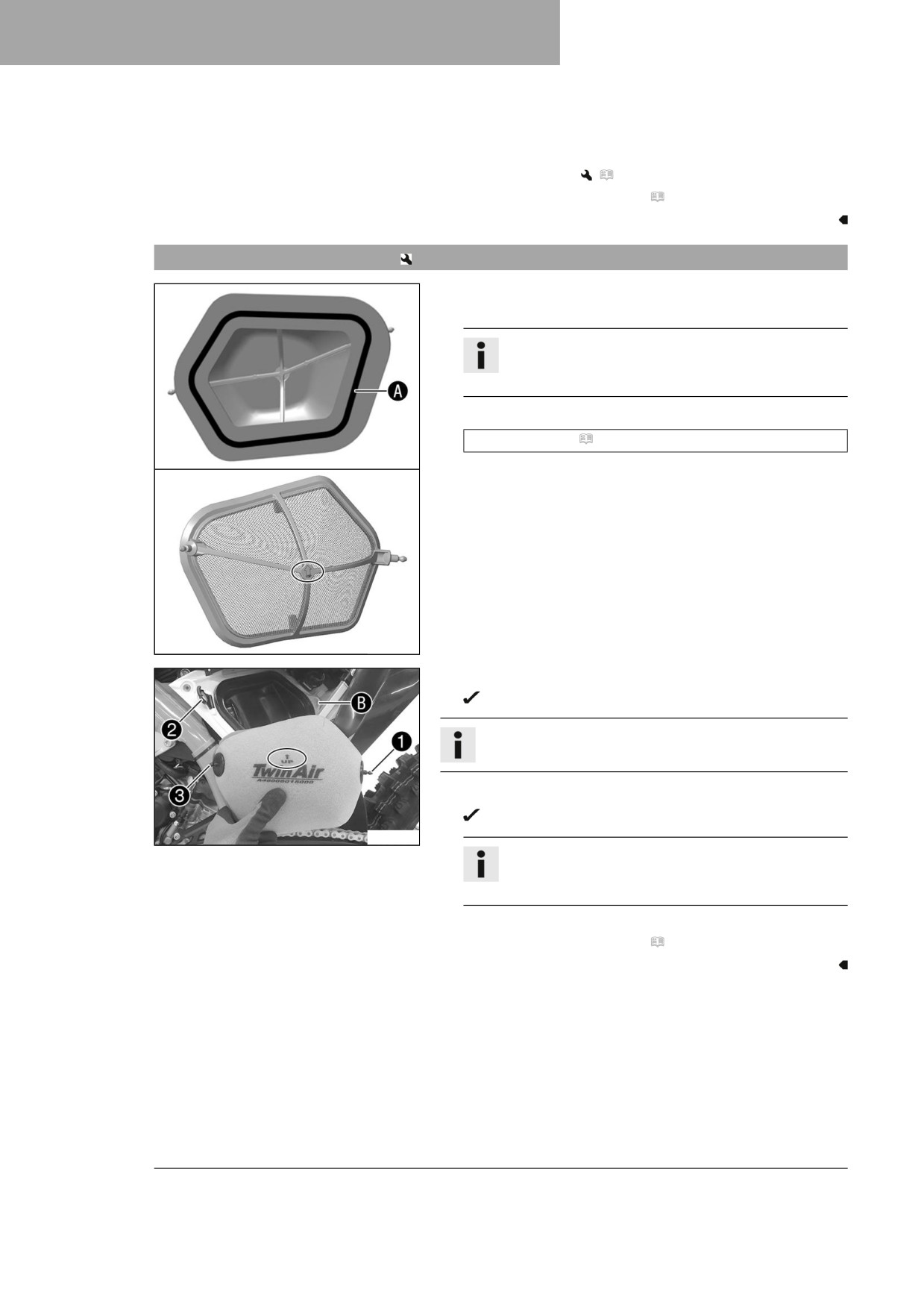
Installing the air filter
Main work
- Mount the clean air filter on the air filter support.
Info
The marking on the air filter support must face
upwards.
- Grease the air filter in area A.
Long-life grease ( p. 142)
F03779-10
- Insert air filter and position retaining pin 1 in bushing B.
The air filter is correctly positioned.
Info
The marking on the air filter must face upwards.
- Insert retaining tab 2.
Retaining pin 3 is secured by retaining tab 2.
F03778-10
Info
If the air filter is not mounted correctly, dust and dirt
may enter the engine and result in damage.
Finishing work
- Install the air filter box cover. ( p. 64)
66
SERVICE WORK ON THE CHASSIS
11
11.29
Securing the air filter box cover
Preparatory work
- Remove the air filter box cover. ( p. 63)
Main work
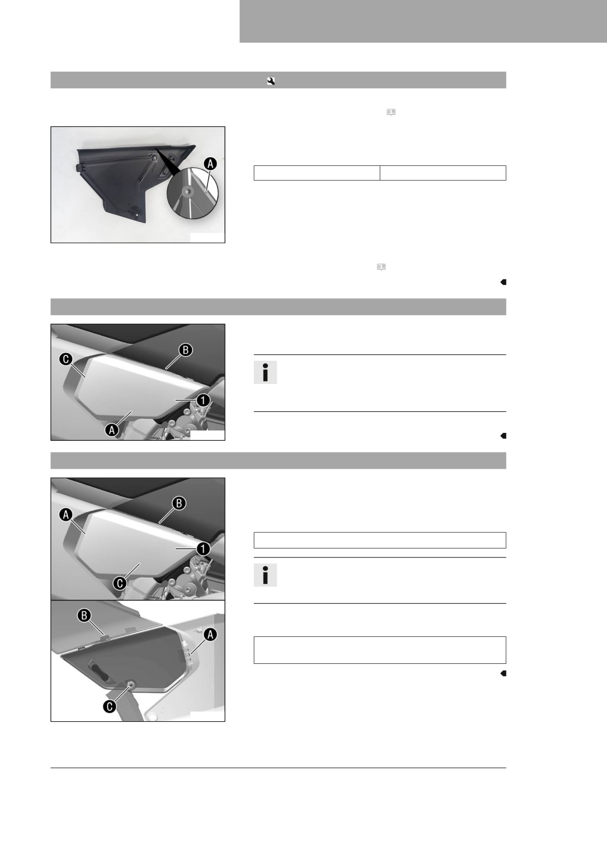
- Drill a hole at marking A.
Guideline
Diameter
6 mm (0.24 in)
A01090-10
Finishing work
- Install the air filter box cover. ( p. 64)
11.30
Removing the right side panel
-
Unhook right side panel 1 in area A, slide forward in
area B and unhook and detach in area C.
Info
If the side panel does not have to be completely
removed, the side panel can remain hooked into
area C and can just be folded open.
-
Take the right side panel off.
A01195-10
11.31
Installing the right side panel
-
Position right side panel 1.
–
Apply some pressure to the side panel in area A and attach
it. Attach it in area B and push it towards the rear.
Guideline
Hold the side cover in area A from the rear.
Info
If the side panel was only folded out, the side panel
does not need to be hooked in again in area A.
-
Press the side panel in area C into the rubber bushing.
Guideline
Ensure that the side panel is correctly hooked in to
areas A, B, and C.
A01196-10
67
11
SERVICE WORK ON THE CHASSIS
11.32
Removing the main silencer
Warning
Danger of burns The exhaust system gets hot when the vehicle is driven.
- Allow the exhaust system to cool down before performing any work on the vehicle.
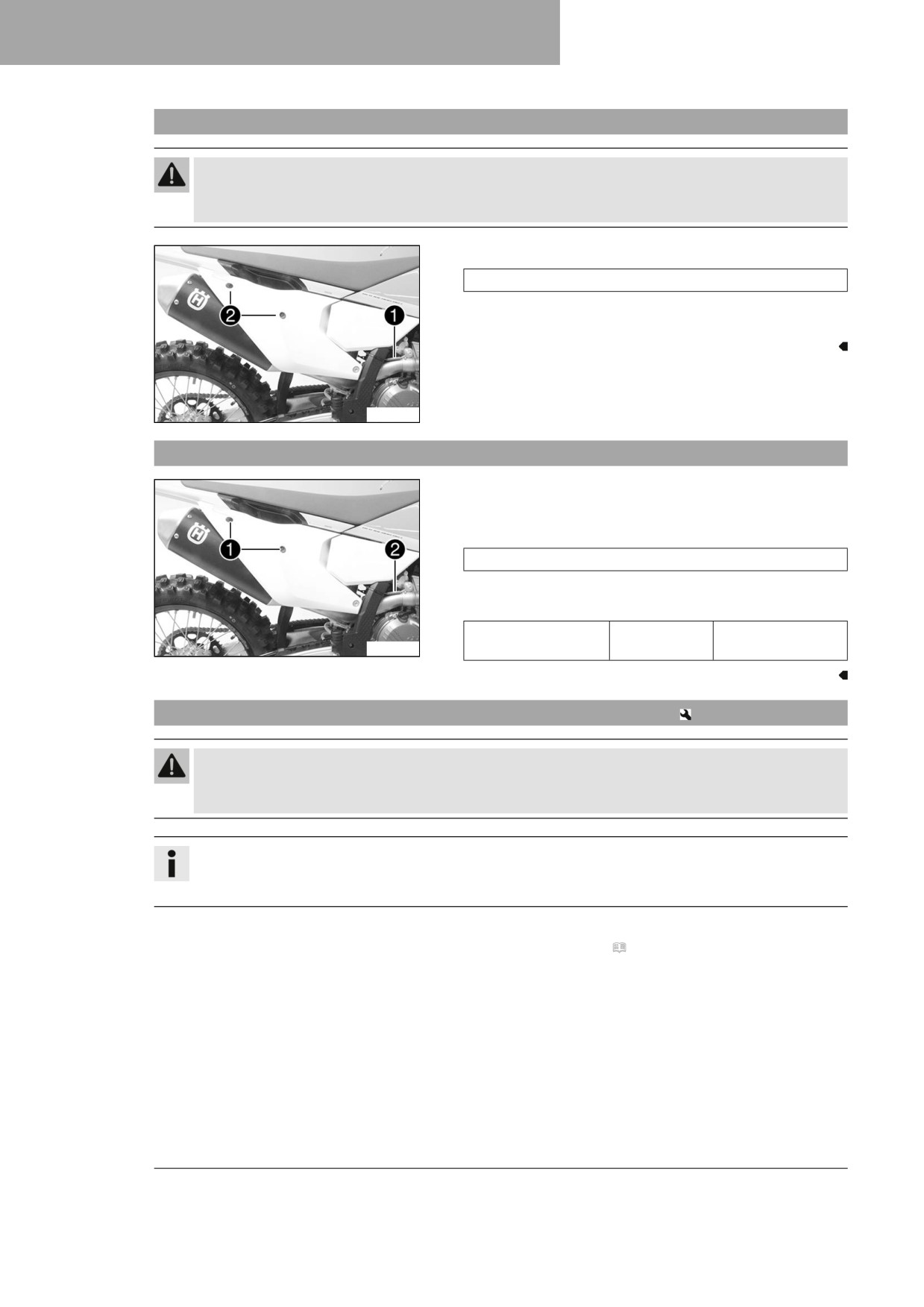
- Detach spring 1.
Spring hook (50305017000C1)
- Remove screws 2 with the washers and take off the main
silencer.
A01181-10
11.33
Installing the main silencer
- Position the main silencer.
- Mount screws 1 with washers, but do not tighten yet.
- Attach spring 2.
Spring hook (50305017000C1)
- Tighten screws 1.
Guideline
Remaining screws,
M6
10 Nm (7.4 lbf ft)
A01181-11
chassis
11.34
Changing the glass fiber yarn filling of the main silencer
Warning
Danger of burns The exhaust system gets hot when the vehicle is driven.
- Allow the exhaust system to cool down before performing any work on the vehicle.
Info
Over time, the fibers of the glass fiber yarn filling escape and the damper "burns" out.
Not only is the noise level higher, but the performance characteristics change.
Preparatory work
- Remove main silencer. ( p. 68)
68
SERVICE WORK ON THE CHASSIS
11
Main work
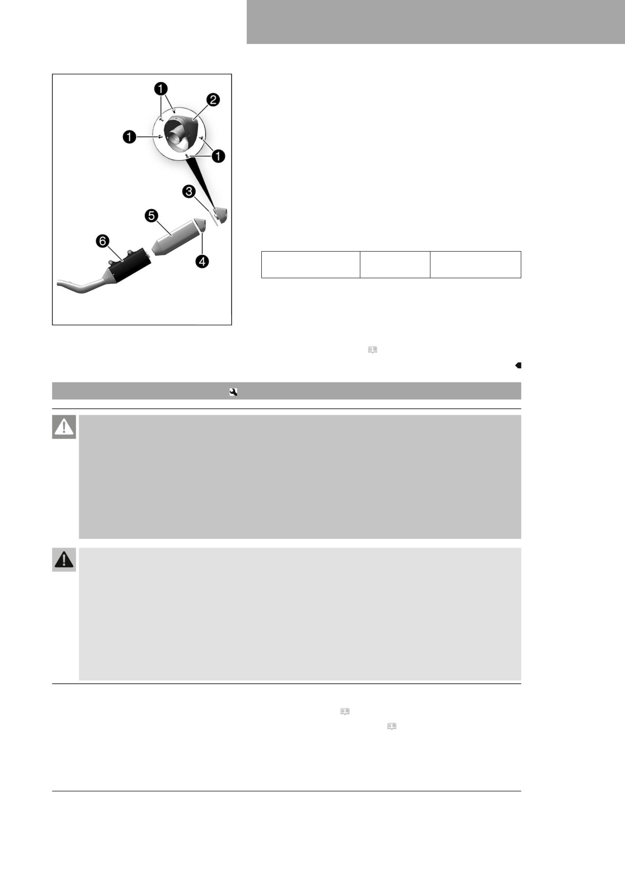
- Remove the screws 1 on the main silencer.
- Take off silencer cap 2 and O-ring 3.
- Pull glass fiber yarn filling 4 out of the silencer cap.
- Pull glass fiber yarn filling 5 from the inner tube.
- Clean the parts that need to be reinstalled and check for
damage.
- Mount new glass fiber yarn filling 5 on the inner tube.
- Position new glass fiber yarn filling 4 in the silencer cap.
- Insert O-ring and silencer cap into outer tube 6.
- Mount and tighten screws 1.
Guideline
Screws on main
M5
7 Nm (5.2 lbf ft)
silencer
F03637-10
Finishing work
- Install the main silencer. ( p. 68)
11.35
Removing the fuel tank
Danger
Fire hazard Fuel is highly flammable.
The fuel in the fuel tank expands when warm and can escape if overfilled.
- Do not fuel the vehicle in the vicinity of open flames or lit cigarettes.
- Switch off the engine for refueling.
- Make sure that no fuel is spilled; particularly not on hot parts of the vehicle.
- If any fuel is spilled, wipe it off immediately.
- Observe the specifications for refueling.
Warning
Danger of poisoning Fuel is harmful to health.
- Avoid skin, eye and clothing contact with fuel.
- Immediately consult a doctor if you swallow fuel.
- Do not inhale fuel vapors.
- Rinse the affected area immediately with plenty of water in the event of contact with the skin.
- Rinse the eyes thoroughly with water, and consult a doctor in case of fuel contact with the eyes.
- Change your clothing if fuel spills on them.
- Keep fuels correctly in a suitable canister, and out of the reach of children.
Preparatory work
- Remove the seat. ( p. 62)
- Remove the right side panel. ( p. 67)
69
11
SERVICE WORK ON THE CHASSIS
Main work
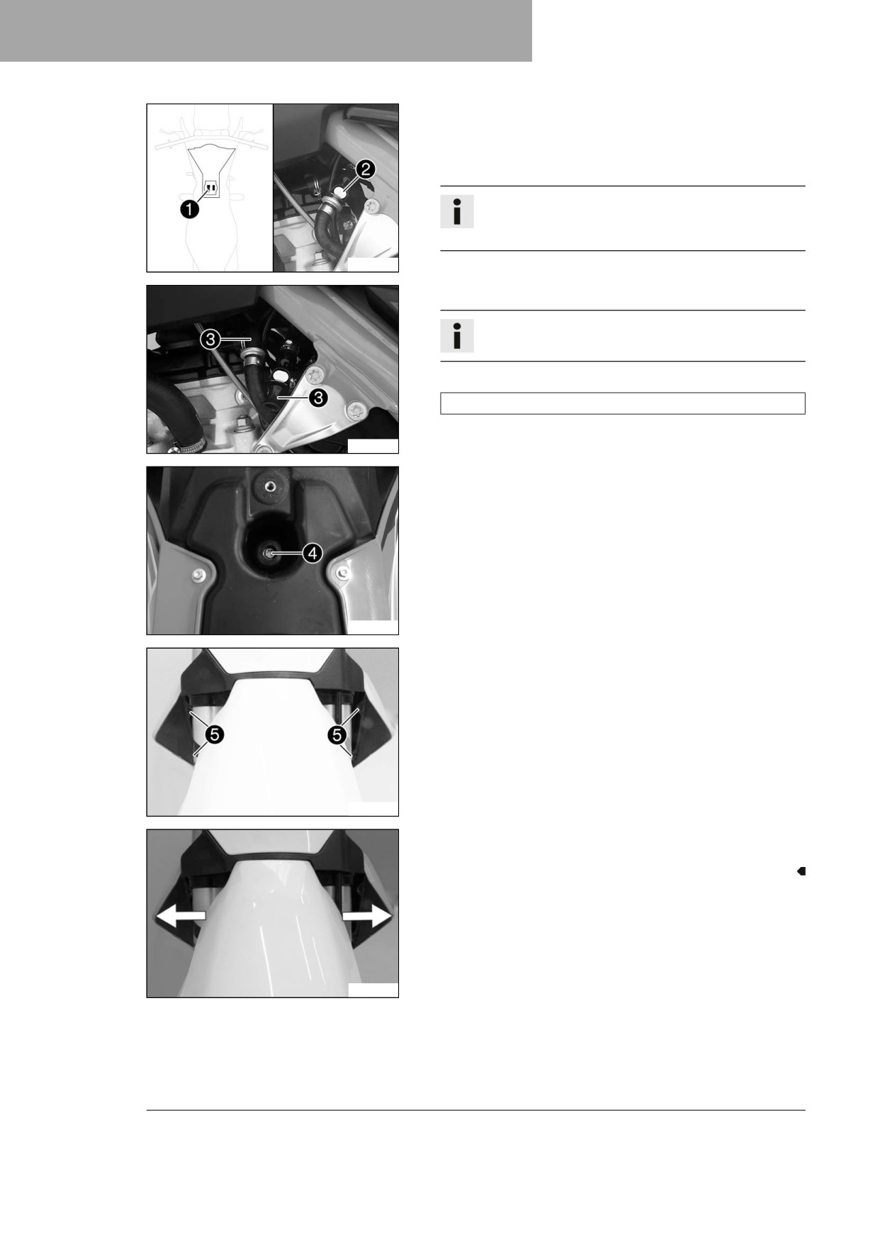
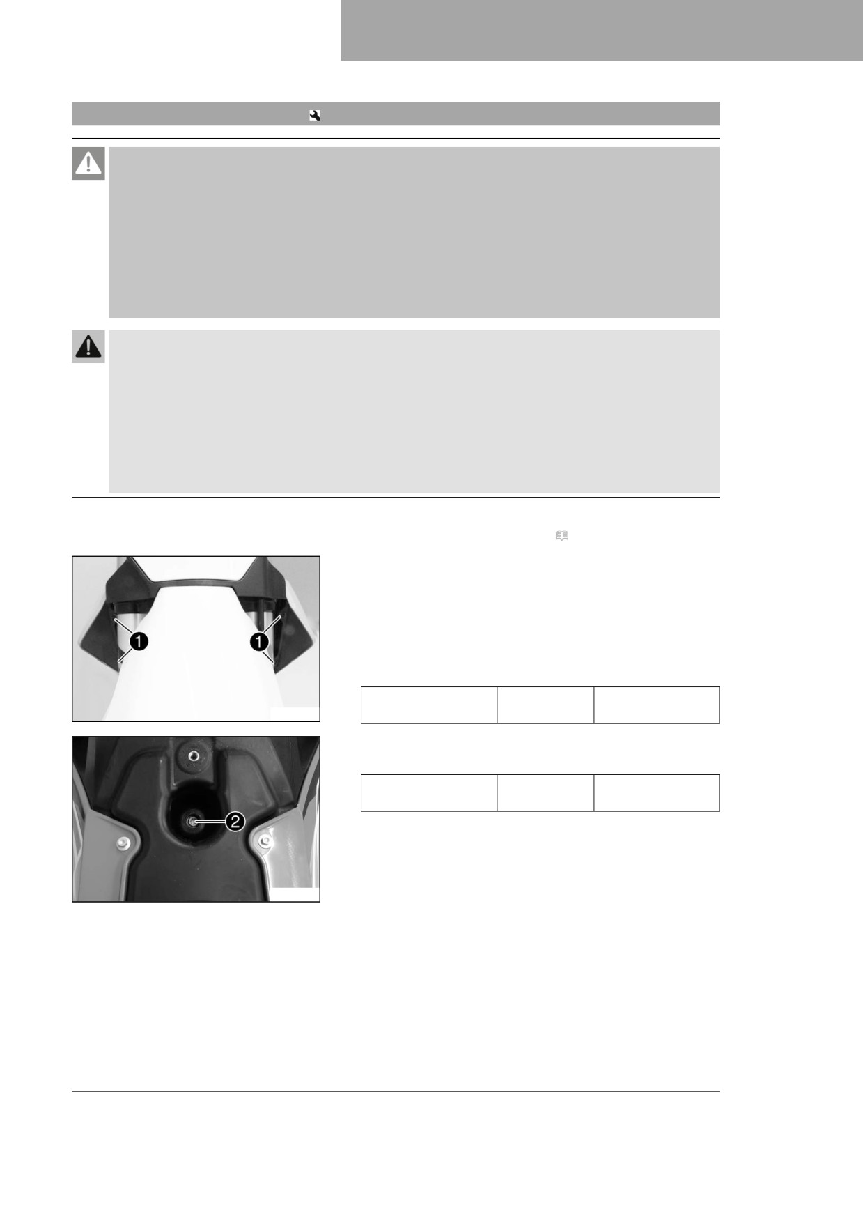
- Unplug fuel pump connector 1.
- Clean quick release coupling 2 thoroughly with
compressed air.
Info
Under no circumstances should dirt enter into the fuel
line. Dirt in the fuel line clogs the injection valve!
H04981-10
- Disconnect the quick release coupling.
Info
Remaining fuel may flow out of the fuel hose.
- Mount wash cap set 3.
Wash cap set (81212016100)
- Pull the fuel tank breather hose off the fuel tank lid.
H04982-10
- Remove screw 4 with the rubber bushing.
H04983-10
- Remove screws 5 with the collar bushings.
A01185-11
- Pull both spoilers laterally off the radiator and lift off the fuel
tank.
A01185-12
70
SERVICE WORK ON THE CHASSIS
11
11.36
Installing the fuel tank
Danger
Fire hazard Fuel is highly flammable.
The fuel in the fuel tank expands when warm and can escape if overfilled.
- Do not fuel the vehicle in the vicinity of open flames or lit cigarettes.
- Switch off the engine for refueling.
- Make sure that no fuel is spilled; particularly not on hot parts of the vehicle.
- If any fuel is spilled, wipe it off immediately.
- Observe the specifications for refueling.
Warning
Danger of poisoning Fuel is harmful to health.
- Avoid skin, eye and clothing contact with fuel.
- Immediately consult a doctor if you swallow fuel.
- Do not inhale fuel vapors.
- Rinse the affected area immediately with plenty of water in the event of contact with the skin.
- Rinse the eyes thoroughly with water, and consult a doctor in case of fuel contact with the eyes.
- Change your clothing if fuel spills on them.
Main work
- Check the throttle cable routing. ( p. 77)
- Position the fuel tank and fit the two spoilers laterally to the
radiator.
- Make sure that no cables or throttle cables are trapped or
damaged.
- Attach the fuel tank breather hose to the fuel tank lid.
- Mount and tighten screws 1 with the collar bushings.
Guideline
Screw, fuel tank
M6
6 Nm (4.4 lbf ft)
A01185-10
spoiler on radiator
- Mount and tighten screw 2 with the rubber bushing.
Guideline
Remaining screws,
M6
10 Nm (7.4 lbf ft)
chassis
H04983-11
71
11
SERVICE WORK ON THE CHASSIS
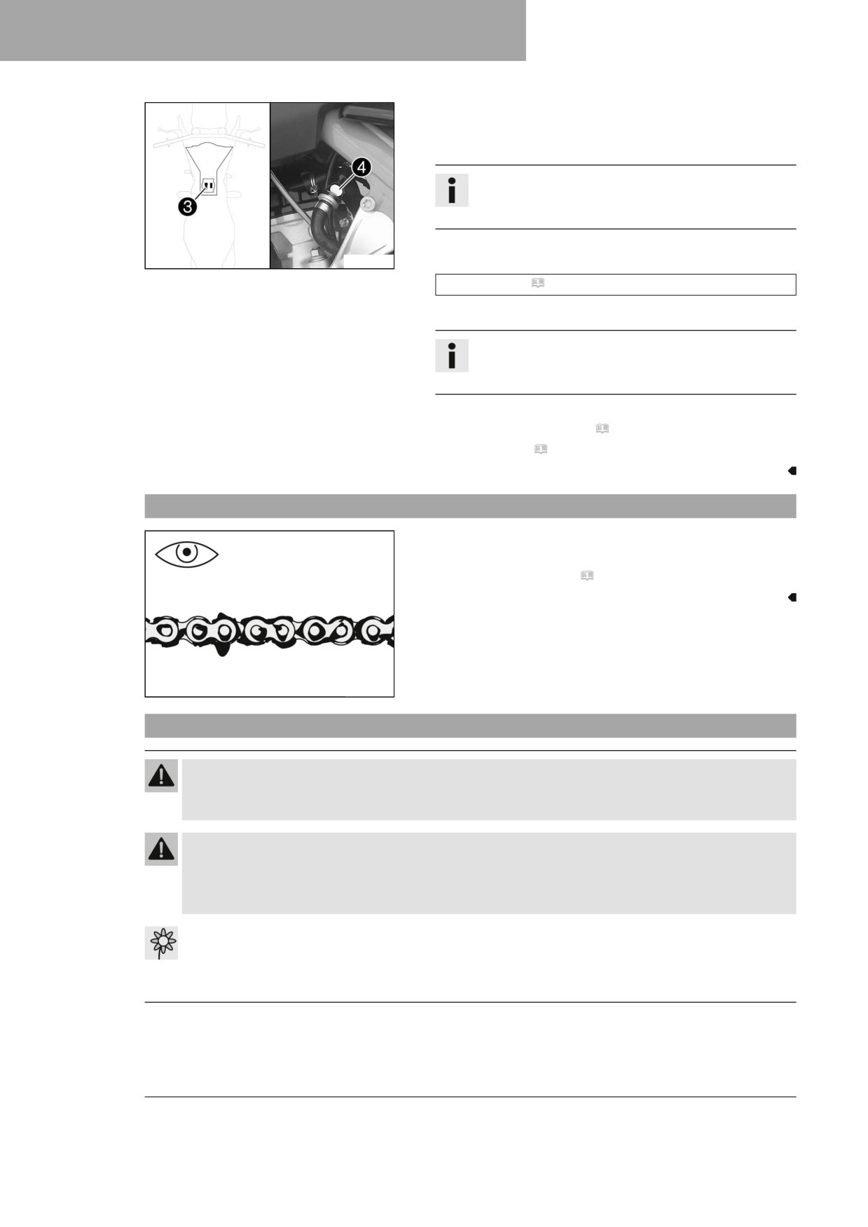
- Plug in fuel pump connector 3.
- Remove the wash cap set and thoroughly clean the quick
release coupling using compressed air.
Info
Under no circumstances should dirt enter into the fuel
line. Dirt in the fuel line clogs the injection valve!
- Spray silicone spray onto a lint-free cleaning cloth and lightly
H04981-11
lubricate the O-ring of the quick-release coupling.
Silicone spray ( p. 143)
- Join the quick-release coupling 4 of the fuel line.
Info
Route the cable and fuel line at a safe distance from
the exhaust system.
Finishing work
- Install the right side panel. ( p. 67)
- Mount the seat. ( p. 62)
11.37
Checking for chain dirt accumulation
- Check the chain for coarse dirt accumulation.
» If the chain is very dirty:
- Clean the chain. ( p. 72)
400678-01
11.38
Cleaning the chain
Warning
Danger of accidents Lubricants on the tires reduces the road grip.
- Remove lubricants from the tires using a suitable cleaning agent.
Warning
Danger of accidents Oil or grease on the brake discs reduces the braking effect.
- Always keep the brake discs free of oil and grease.
- Clean the brake discs with brake cleaner when necessary.
Note
Environmental hazard Hazardous substances cause environmental damage.
- Dispose of oils, grease, filters, fuel, cleaning agents, brake fluid, etc., correctly and in compliance
with the applicable regulations.
72
SERVICE WORK ON THE CHASSIS
11
Info
The service life of the chain depends largely on its maintenance.
Preparatory work
- Raise the motorcycle with a lift stand. ( p. 49)
Main work
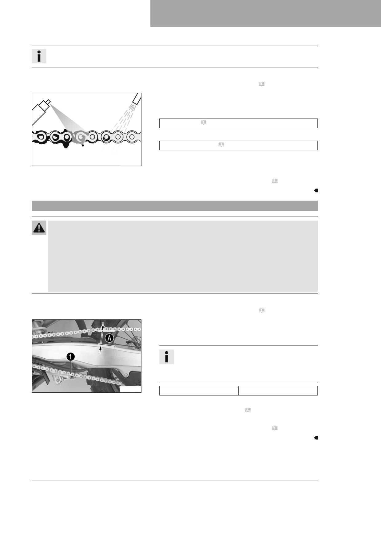
- Rinse off loose dirt with a soft jet of water.
- Remove old grease residue with chain cleaner.
Chain cleaner ( p. 142)
- After drying, apply chain spray.
Off-road chain spray ( p. 142)
400725-01
Finishing work
- Remove the motorcycle from the lift stand. ( p. 49)
11.39
Checking the chain tension
Warning
Danger of accidents Incorrect chain tension damages components and results in accidents.
If the chain is tensioned too much, the chain, engine sprocket, rear sprocket, transmission and rear
wheel bearings wear more quickly. Some components may break if overloaded.
If the chain is too loose, the chain may fall off the engine sprocket or the rear sprocket. As a result, the
rear wheel locks or the engine will be damaged.
- Check the chain tension regularly.
- Set the chain tension in accordance with the specification.
Preparatory work
- Raise the motorcycle with a lift stand. ( p. 49)
Main work
- Pull the chain at the end of the chain sliding piece upward to
measure chain tension A.
Info
Lower chain section 1 must be taut.
Chain wear is not always even, so you should repeat
this measurement at different chain positions.
F03680-10
Chain tension
58 … 61 mm (2.28 … 2.4 in)
» If the chain tension does not meet the specification:
- Adjust the chain tension. ( p. 74)
Finishing work
- Remove the motorcycle from the lift stand. ( p. 49)
73
11
SERVICE WORK ON THE CHASSIS
11.40
Adjusting the chain tension
Warning
Danger of accidents Incorrect chain tension damages components and results in accidents.
If the chain is tensioned too much, the chain, engine sprocket, rear sprocket, transmission and rear
wheel bearings wear more quickly. Some components may break if overloaded.
If the chain is too loose, the chain may fall off the engine sprocket or the rear sprocket. As a result, the
rear wheel locks or the engine will be damaged.
-
Check the chain tension regularly.
–
Set the chain tension in accordance with the specification.
Preparatory work
- Raise the motorcycle with a lift stand. ( p. 49)
- Check the chain tension. ( p. 73)
Main work
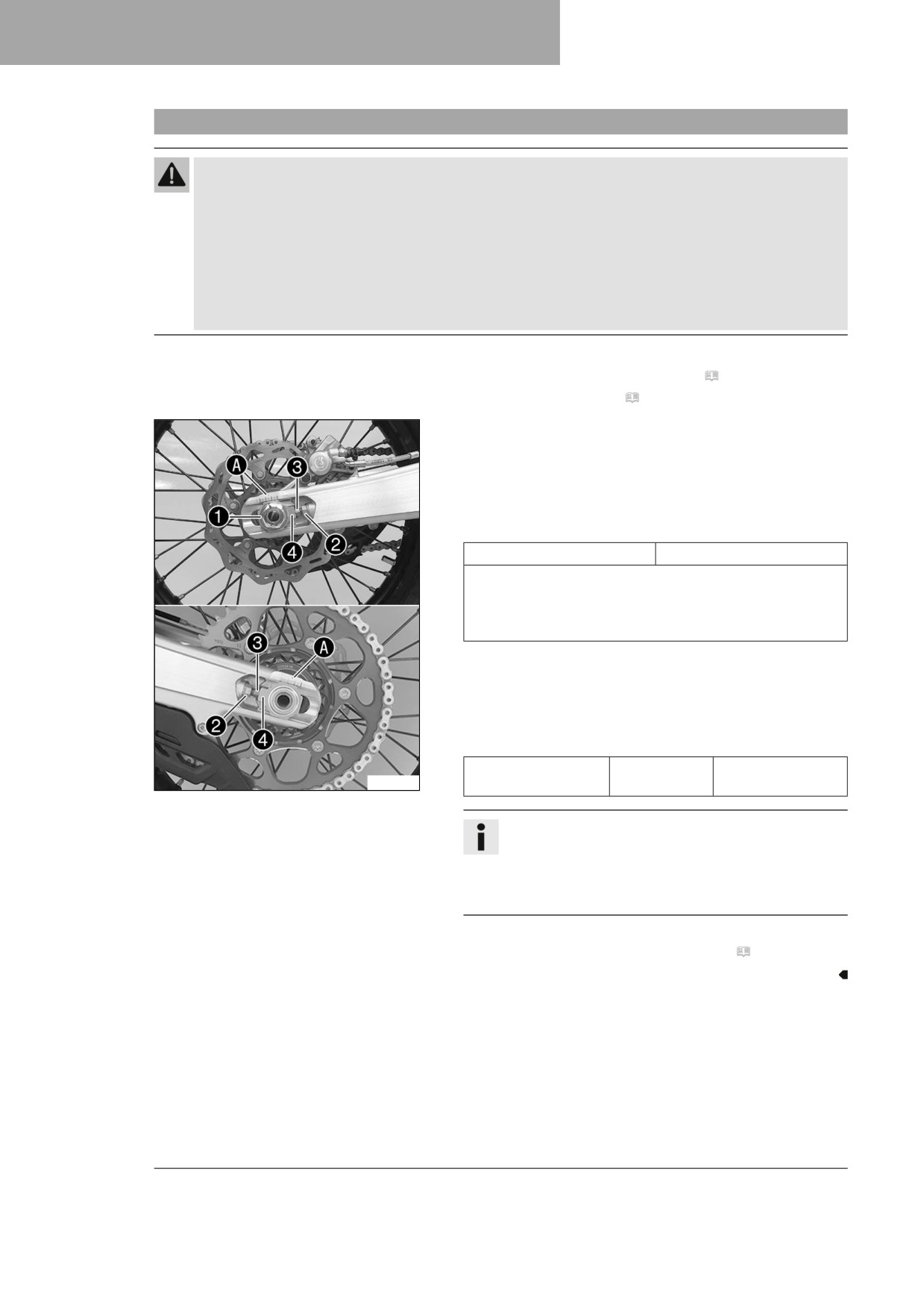
- Loosen nut 1.
- Loosen nuts 2.
- Adjust the chain tension by turning adjusting screws 3 left
and right.
Guideline
Chain tension
58 … 61 mm (2.28 … 2.4 in)
Turn adjusting screws 3 on the left and right so that the
markings on the left and right chain adjusters are in the
same position relative to reference marks A. The rear
wheel is then correctly aligned.
- Tighten nuts 2.
- Make sure that chain adjusters 4 are fitted correctly on
adjusting screws 3.
- Tighten nut 1.
Guideline
Nut, wheel spindle,
M22x1.5
80 Nm (59 lbf ft)
F03681-10
rear
Info
The wide adjustment range of the chain adjusters
(32 mm (1.26 in)) enables different secondary ratios
with the same chain length.
Chain adjusters 4 can be turned by 180°.
Finishing work
- Remove the motorcycle from the lift stand. ( p. 49)
74
SERVICE WORK ON THE CHASSIS
11
11.41
Checking the chain, rear sprocket, engine sprocket, and chain guide
Preparatory work
- Raise the motorcycle with a lift stand. ( p. 49)
Main work
-
Shift the transmission into neutral.
–
Check the chain, rear sprocket and engine sprocket for wear.
» If the chain, rear sprocket or engine sprocket is worn:
- Change the drivetrain kit.
Info
The engine sprocket, rear sprocket and chain
should always be replaced together.
400227-01
-
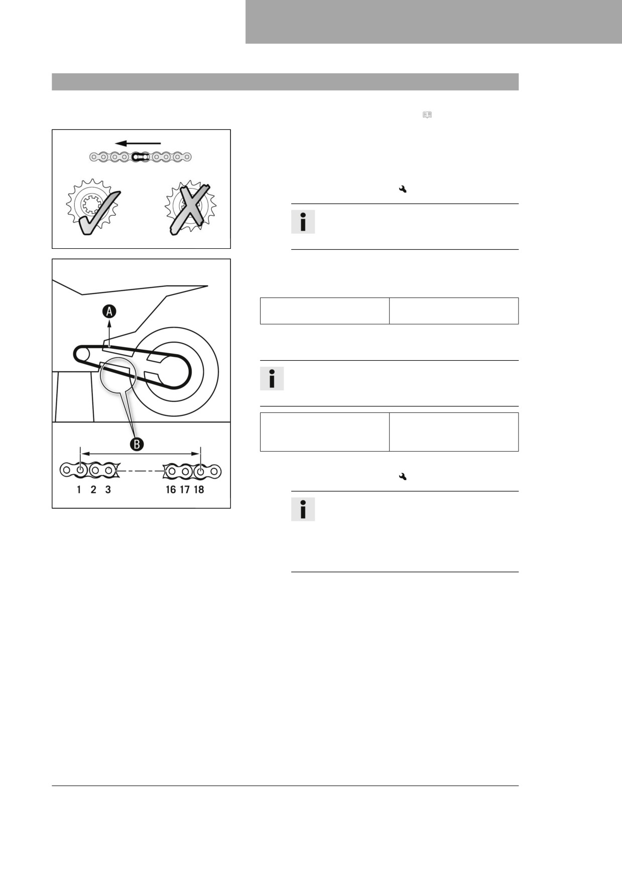
Pull on the top section of the chain with the specified
weight A.
Guideline
Weight, chain wear mea-
10 … 15 kg (22 … 33 lb.)
surement
-
Measure distance B of 18 chain rollers in the lower chain
section.
Info
Chain wear is not always even, so repeat this mea-
surement at different positions on the chain.
272 mm (10.71 in)
Maximum distance B from
18 chain rollers at the
longest chain section
» If distance B is greater than the specified measurement:
- Change the drivetrain kit.
400987-10
Info
When a new chain is mounted, the rear
sprocket and the engine sprocket should also
be changed.
New chains wear out faster on an old, worn
rear sprocket or engine sprocket.
75
11
SERVICE WORK ON THE CHASSIS
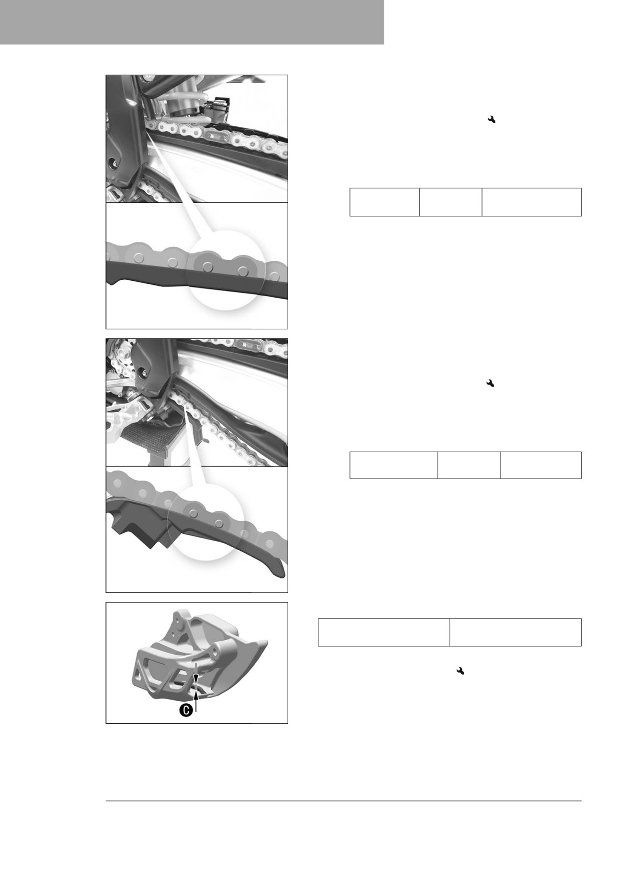
- Check the chain sliding guard for wear.
» If the lower edge of the chain pins is in line with, or below,
the chain sliding guard:
- Change the chain sliding guard.
- Check that the chain sliding guard is firmly seated.
» If the chain sliding guard is loose:
- Tighten screws on the chain sliding guard.
Guideline
Screw, chain
M6
6 Nm (4.4 lbf ft)
sliding guard
Loctite®243™
A01086-10
- Check the chain sliding piece for wear.
» If the lower edge of the chain pins is in line with or below
the chain sliding piece:
- Change the chain sliding piece.
- Check that the chain sliding piece is firmly seated.
» If the chain sliding piece is loose:
- Tighten screw on the chain sliding piece.
Guideline
Screw, chain slid-
M8
15 Nm
ing piece
(11.1 lbf ft)
A01087-10
- Check the chain guide with a slide gage for dimension C.
6 mm (0.24 in)
Minimum thickness C of
the chain guide
» If the measured value is less than the specified value:
- Change the chain guide.
F03687-10
76
SERVICE WORK ON THE CHASSIS
11
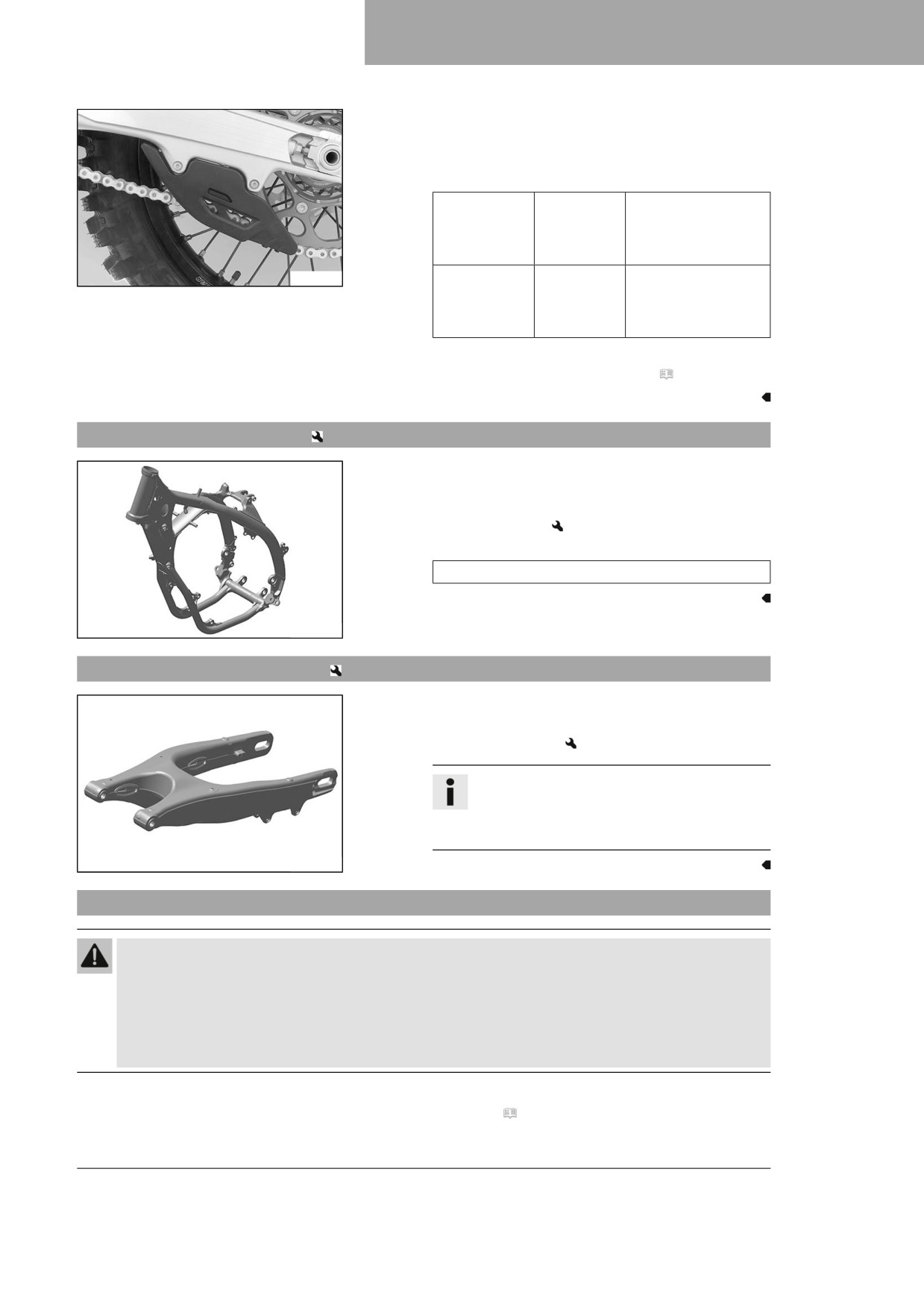
– Check that the chain guide is firmly seated.
» If the chain guide is loose:
- Tighten the screws on the chain guide.
Guideline
Screw, chain
M6
10 Nm (7.4 lbf ft)
guide on link
fork at the
front
F03682-01
Screw, chain
M6
10 Nm (7.4 lbf ft)
guide on link
Loctite®243™
fork at the
rear
Finishing work
- Remove the motorcycle from the lift stand. ( p. 49)
11.42
Checking the frame
- Check the frame for damage, cracks, and deformation.
» If the frame shows signs of damage, cracks, or deforma-
tion:
- Change the frame.
Guideline
Repairs on the frame are not permitted.
F03645-01
11.43
Checking the link fork
- Check the link fork for damage, cracking, and deformation.
» If the link fork exhibits damage, cracking, or deformation:
- Change the link fork.
Info
Always replace a damaged link fork. Repair of
the link fork is not authorized by Husqvarna
Motorcycles.
F03646-01
11.44
Checking the throttle cable routing
Warning
Danger of accidents The throttle cable can become kinked, trapped or blocked if it is not routed cor-
rectly.
If the throttle cable is kinked, trapped or blocked, the speed can no longer be controlled.
- Make sure that the throttle cable routing and the play in throttle cable complies with the specifica-
tion.
Preparatory work
- Remove the seat. ( p. 62)
77
11
SERVICE WORK ON THE CHASSIS
- Remove the right side panel. ( p. 67)
- Remove the fuel tank.
(
p. 69)
Main work
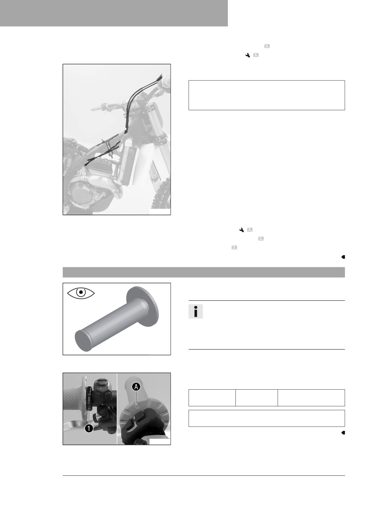
- Check the throttle cable routing.
Both throttle cables must be routed to the throttle valve
body side by side on the back of the handlebars and above
the fuel tank roller. Both throttle cables must be secured
behind the rubber strap of the fuel tank support.
» If the throttle cable routing is not as specified:
- Correct the throttle cable routing.
A01085-10
Finishing work
- Install the fuel tank.
(
p. 71)
– Install the right side panel. ( p. 67)
- Mount the seat. ( p. 62)
11.45
Checking the rubber grips
- Check the rubber grips on the handlebar for damage, wear,
and looseness.
Info
The rubber grips are vulcanized onto a sleeve on the
left and onto the handle tube of the throttle grip on the
right. The left sleeve is clamped onto the handlebar.
The rubber grip can only be replaced with the sleeve
or the throttle tube.
401197-01
» If a rubber grip is damaged or worn:
- Change the rubber grip.
- Check that screw 1 is firmly seated.
Guideline
Screw, fixed
M4
5 Nm (3.7 lbf ft)
grip
Loctite®243™
Diamond A must be positioned visibly as shown in the
figure.
F03684-10
78
SERVICE WORK ON THE CHASSIS
11
11.46
Programming the quickshifter
Info
If the shifting performance of the quickshifter starts to decrease, it must be reprogrammed.
- Carry out start procedure. ( p. 26)
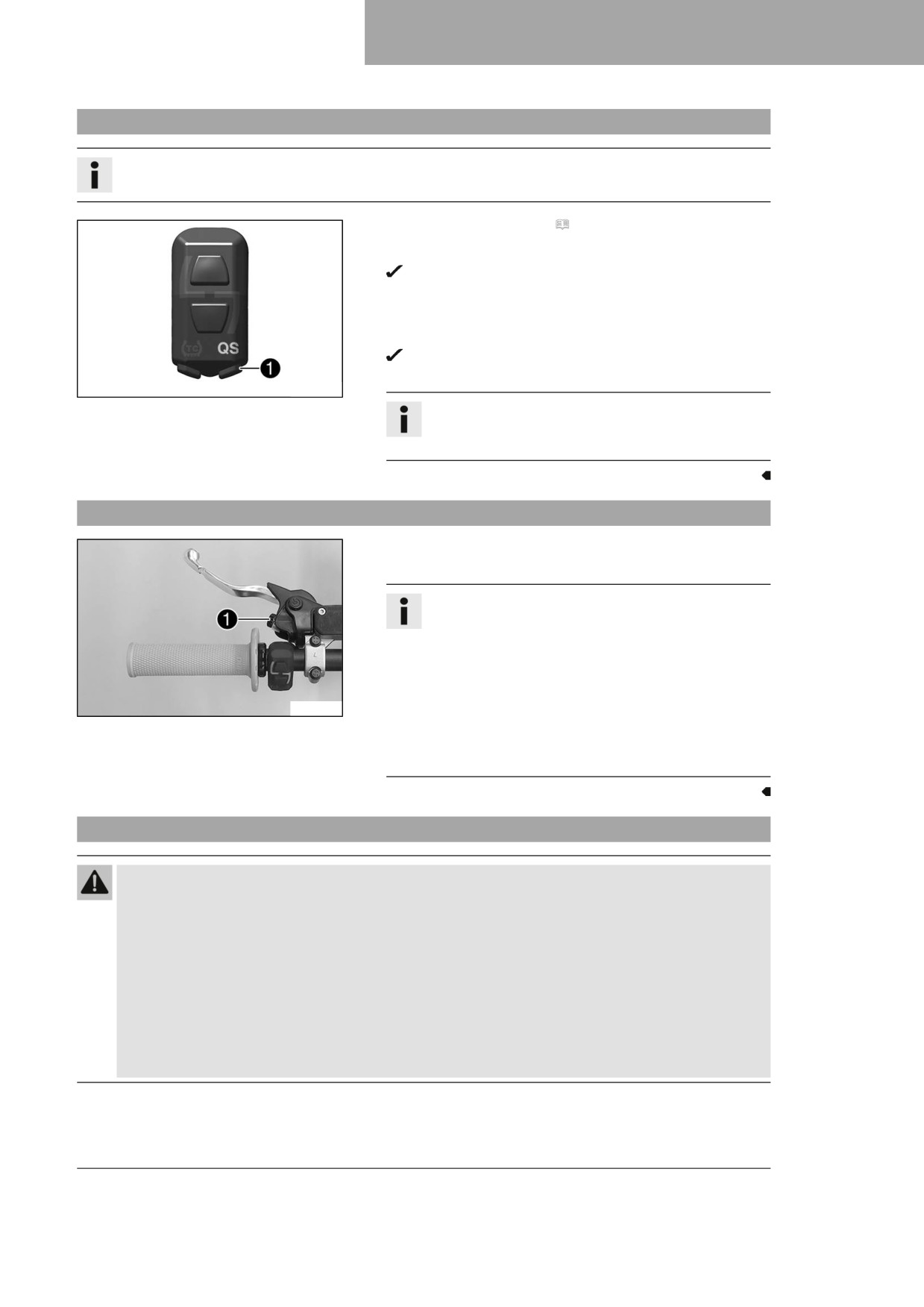
- Press and hold the QS button 1 for at least 10 seconds.
The QS indicator lamp flashes.
- Pull the clutch lever, engage first-gear and press the shift
lever as far down as it will go for at least a second.
- Briefly press the QS button 1.
The QS indicator lamp lights up blue, the teaching proce-
dure was successful.
F03760-12
Info
If the quickshifter cannot be activated, the teaching
procedure was unsuccessful and must be repeated.
11.47
Adjusting the basic position of the clutch lever
- Adjust the basic position of the clutch lever to your hand size
by turning adjusting screw 1.
Info
Turn the adjusting screw counterclockwise to
decrease the distance between the clutch lever and
the handlebar.
Turn the adjusting screw clockwise to increase the
distance between the clutch lever and the handlebar.
F03647-11
The range of adjustment is limited.
Only turn the adjusting screw by hand, and do not use
force.
Do not make any adjustments while riding.
11.48
Checking/correcting the fluid level of hydraulic clutch
Warning
Skin irritation Brake fluid is a harmful substance.
- Keep brake fluid out of the reach of children.
- Wear suitable protective clothing and safety glasses.
- Do not allow brake fluid to come into contact with the skin, the eyes or clothing.
- Consult a doctor immediately if brake fluid has been swallowed.
- Rinse the affected area with plenty of water in the event of contact with the skin.
- Rinse eyes thoroughly with water immediately and consult a doctor if brake fluid comes into contact
with the eyes.
- If brake fluid spills on to your clothing, change the clothing.
79
11
SERVICE WORK ON THE CHASSIS
Info
The fluid level rises with increasing wear of the clutch facing discs.
Avoid contact between brake fluid and painted parts. Brake fluid corrodes paint.
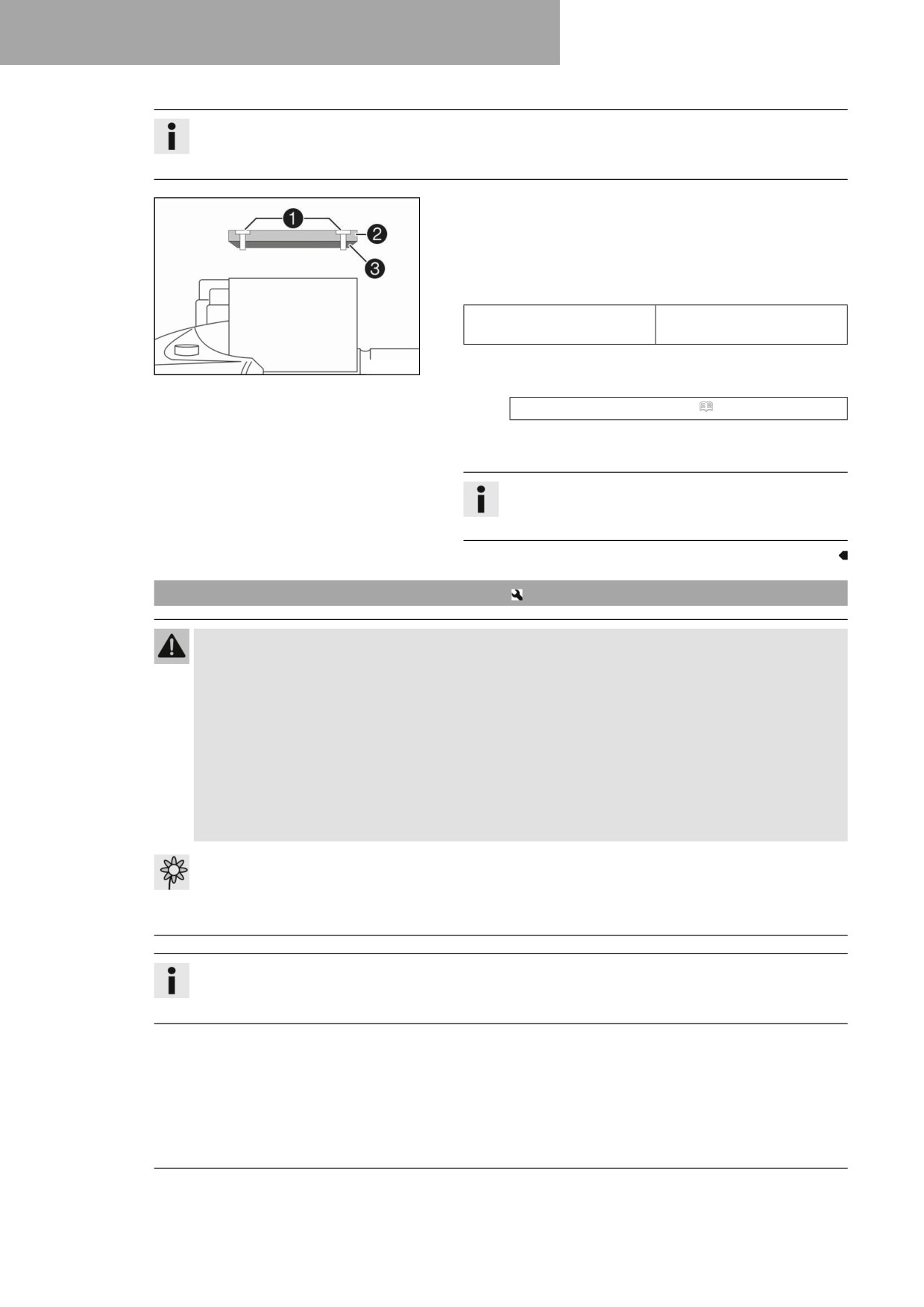
- Move the hydraulic clutch fluid reservoir mounted on the han-
dlebar into a horizontal position.
- Remove screws 1.
- Take off cover 2 with membrane 3.
- Check the fluid level.
Fluid level below container
4 mm (0.16 in)
rim
» If the fluid level does not meet specifications:
H04933-10
- Correct the fluid level of the hydraulic clutch.
Brake fluid DOT 4 / DOT 5.1 ( p. 140)
- Position the cover with the membrane. Mount and tighten the
screws.
Info
Use water to immediately clean up any brake fluid that
has overflowed or spilled.
11.49
Changing the hydraulic clutch fluid
Warning
Skin irritation Brake fluid is a harmful substance.
- Keep brake fluid out of the reach of children.
- Wear suitable protective clothing and safety glasses.
- Do not allow brake fluid to come into contact with the skin, the eyes or clothing.
- Consult a doctor immediately if brake fluid has been swallowed.
- Rinse the affected area with plenty of water in the event of contact with the skin.
- Rinse eyes thoroughly with water immediately and consult a doctor if brake fluid comes into contact
with the eyes.
- If brake fluid spills on to your clothing, change the clothing.
Note
Environmental hazard Hazardous substances cause environmental damage.
- Dispose of oils, grease, filters, fuel, cleaning agents, brake fluid, etc., correctly and in compliance
with the applicable regulations.
Info
The fluid level rises with increasing wear of the clutch facing discs.
Avoid contact between brake fluid and painted parts. Brake fluid corrodes paint.
80