HUSQVARNA FC 250. OWNER'S MANUAL (2024) - page 1
TABLE OF CONTENTS
TABLE OF CONTENTS
1
MEANS OF REPRESENTATION
5
6.15
Plug-in stand
20
1.1
Symbols used
5
7
PREPARING FOR USE
21
1.2
Formats used
5
7.1
Advice on preparing for first use
21
2
SAFETY ADVICE
6
7.2
Running in the engine
22
7.3
Starting power of lithium-ion
2.1
Use definition - intended use
6
batteries at low temperatures
22
2.2
Misuse
6
7.4
Preparing the vehicle for difficult
2.3
Safety advice
6
operating conditions
23
2.4
Degrees of risk and symbols
6
7.5
Preparing the vehicle for rides on
2.5
Tampering warning
7
dry sand
23
2.6
Safe operation
7
7.6
Preparing the vehicle for rides on
2.7
Protective clothing
8
wet sand
24
2.8
Work rules
8
7.7
Preparing the vehicle for rides on
wet and muddy circuits
24
2.9
Environment
8
7.8
Preparing vehicle for high
2.10
Owner's Manual
8
temperatures or slow riding
25
3
IMPORTANT NOTES
10
7.9
Preparing the vehicle for low
temperatures or snow
25
3.1
Manufacturer warranty, implied
warranty
10
8
RIDING INSTRUCTIONS
26
3.2
Fuel, auxiliary substances
10
8.1
Checks and maintenance measures
3.3
Spare parts, accessories
10
when preparing for use
26
3.4
Service
10
8.2
Starting the vehicle
26
3.5
Figures
10
8.3
Activating launch control
27
3.6
Customer service
10
8.4
Activating traction control
28
4
VIEW OF VEHICLE
11
8.5
Starting off
28
8.6
Quickshifter
29
4.1
View of vehicle, front left (example)
11
8.7
Activating the quickshifter
29
4.2
View of vehicle, rear right
8.8
Shifting, riding
29
(example)
12
8.9
Applying the brakes
30
5
SERIAL NUMBERS
13
8.10
Stopping, parking
31
8.11
Transporting
32
5.1
Vehicle identification number
13
8.12
Refueling
32
5.2
Steering head label
13
5.3
Engine number
13
9
SERVICE SCHEDULE
34
5.4
Fork article number
13
9.1
Additional information
34
5.5
Shock absorber article number
14
9.2
Service schedule
34
6
CONTROLS
15
10
TUNING THE CHASSIS
36
6.1
Clutch lever
15
10.1
Checking the basic chassis setting
6.2
Hand brake lever
15
with rider's weight
36
6.3
Throttle grip
15
10.2
Air suspension XACT
36
6.4
Stop button
15
10.3
Compression damping of the shock
6.5
Start button
16
absorber
37
6.6
Combination switch
16
10.4
Adjusting the low-speed
6.7
Overview of indicator lights
16
compression damping of the shock
6.8
Combination instrument
17
absorber
37
6.9
Opening fuel tank filler cap
17
10.5
Adjusting the high-speed
6.10
Closing the fuel tank filler cap
18
compression damping of the shock
absorber
38
6.11
Cold start button
18
10.6
Adjusting the rebound damping of
6.12
Idle speed adjusting screw
19
the shock absorber
38
6.13
Shift lever
19
10.7
Measuring the dimension of the rear
6.14
Foot brake lever
20
wheel unloaded
39
2
TABLE OF CONTENTS
10.8
Checking the static sag of the
11.30
Removing the right side panel
67
shock absorber
40
11.31
Installing the right side panel
67
10.9
Checking the riding sag of the
11.32
Removing the main silencer
68
shock absorber
40
11.33
Installing the main silencer
68
10.10
Adjusting the spring preload of the
11.34
Changing the glass fiber yarn filling
shock absorber
41
of the main silencer
68
10.11
Adjusting the riding sag
42
11.35
Removing the fuel tank
69
10.12
Checking the basic setting of the
11.36
Installing the fuel tank
71
fork
43
11.37
Checking for chain dirt
10.13
Adjusting the fork air pressure
43
accumulation
72
10.14
Adjusting the compression damping
11.38
Cleaning the chain
72
of the fork
44
11.39
Checking the chain tension
73
10.15
Adjusting the rebound damping of
11.40
Adjusting the chain tension
74
the fork
45
11.41
Checking the chain, rear sprocket,
10.16
Handlebar position
46
engine sprocket, and chain guide
75
10.17
Adjusting the handlebar position
46
11.42
Checking the frame
77
11
SERVICE WORK ON THE CHASSIS
49
11.43
Checking the link fork
77
11.44
Checking the throttle cable routing
77
11.1
Raising the motorcycle with a lift
11.45
Checking the rubber grips
78
stand
49
11.46
Programming the quickshifter
79
11.2
Removing the motorcycle from the
lift stand
49
11.47
Adjusting the basic position of the
clutch lever
79
11.3
Bleeding the fork legs
50
11.48
Checking/correcting the fluid level
11.4
Cleaning the dust boots of the fork
of hydraulic clutch
79
legs
50
11.49
Changing the hydraulic clutch
11.5
Removing the fork protector
51
fluid
80
11.6
Installing the fork protector
51
11.7
Removing the frame protector
51
12
BRAKE SYSTEM
82
11.8
Installing the frame protector
52
12.1
Checking the free travel of the hand
11.9
Removing the fork legs
52
brake lever
82
11.10
Installing the fork legs
52
12.2
Adjusting the basic position of the
11.11
Removing the lower triple clamp
53
hand brake lever
82
11.12
Installing the lower triple clamp
54
12.3
Checking the brake discs
82
11.13
Checking the steering head bearing
12.4
Checking the front brake fluid level
83
play
56
12.5
Adding front brake fluid
84
11.14
Adjusting steering head bearing
12.6
Checking that the brake linings of
play
57
the front brake are secured
85
11.15
Lubricating the steering head
12.7
Changing the brake linings of the
bearing
57
front brake
86
11.16
Removing the start number plate
58
12.8
Checking the free travel of foot
11.17
Installing the start number plate
58
brake lever
88
11.18
Removing front fender
58
12.9
Adjusting the basic position of the
11.19
Installing the front fender
59
foot brake lever
89
11.20
Removing the shock absorber
59
12.10
Checking the rear brake fluid level
89
11.21
Installing the shock absorber
60
12.11
Adding rear brake fluid
90
11.22
Removing the seat
62
12.12
Checking that the brake linings of
11.23
Mounting the seat
62
the rear brake are secured
91
11.24
Removing the air filter box cover
63
12.13
Changing the rear brake linings
92
11.25
Installing the air filter box cover
64
13
WHEELS, TIRES
95
11.26
Removing the air filter
65
13.1
Removing the front wheel
95
11.27
Cleaning the air filter and air filter
box
65
13.2
Installing the front wheel
96
11.28
Installing the air filter
66
13.3
Removing the rear wheel
96
11.29
Securing the air filter box cover
67
13.4
Installing the rear wheel
97
3
TABLE OF CONTENTS
13.5
Checking the tire condition
99
21
BLINK CODE
128
13.6
Checking tire pressure
99
22
TECHNICAL SPECIFICATIONS
130
13.7
Checking the spoke tension
100
22.1
Engine
130
14
ELECTRICAL SYSTEM
101
22.2
Engine tightening torques
131
14.1
Removing the 12-V battery
101
22.3
Capacities
133
14.2
Installing the 12-V battery
102
22.3.1
Engine oil
133
14.3
Charging the 12-V battery
103
22.3.2
Coolant
133
14.4
Changing the main fuse
104
22.3.3
Fuel
133
14.5
Changing the fuse of the fuel
22.4
Chassis
133
pump
105
22.5
Electrical system
134
14.6
Diagnostics connector
106
22.6
Tires
134
22.7
Fork
135
15
COOLING SYSTEM
107
22.7.1
FC 250 EU
135
15.1
Cooling system
107
22.7.2
FC 250 US
135
15.2
Checking the antifreeze and
22.8
Shock absorber
136
coolant level
107
22.8.1
FC 250 EU
136
15.3
Checking the coolant level
108
22.8.2
FC 250 US
136
15.4
Draining the coolant
108
22.9
Chassis tightening torques
137
15.5
Refilling with coolant
109
15.6
Changing the coolant
110
23
SUBSTANCES
140
16
TUNING THE ENGINE
111
24
AUXILIARY SUBSTANCES
142
16.1
Checking the play in the throttle
25
STANDARDS
144
cable
111
26
INDEX OF SPECIAL TERMS
145
16.2
Adjusting the play in the throttle
cable
111
27
LIST OF ABBREVIATIONS
146
16.3
Adjusting the characteristic map of
28
LIST OF SYMBOLS
147
the throttle response
112
16.4
Changing the mapping
114
28.1
Yellow and orange symbols
147
16.5
Adjusting the idle speed
114
28.2
Green and blue symbols
147
16.6
Programming the throttle valve
INDEX
148
position
115
16.7
Checking the basic position of the
shift lever
116
16.8
Adjusting the basic position of the
shift lever
116
17
SERVICE WORK ON THE ENGINE
117
17.1
Changing the fuel screen
117
17.2
Checking the engine oil level
118
17.3
Changing the engine oil and oil
filter, cleaning the oil screen
119
17.4
Adding engine oil
121
18
CLEANING, CARE
122
18.1
Cleaning the motorcycle
122
19
STORAGE
124
19.1
Storage
124
19.2
Putting into operation after
storage
125
20
TROUBLESHOOTING
126
4
MEANS OF REPRESENTATION
1
1.1
Symbols used
The meaning of specific symbols is described below.
Indicates an expected reaction (e.g., of a work step or a function).
Indicates an unexpected reaction (e.g., of a work step or a function).
Indicates work that requires expert knowledge and technical understanding.
In the interests of your own safety, have these jobs performed by an authorized
Husqvarna Motorcycles workshop. Your motorcycle will be cared for there to the highest
degree by specially trained experts using the special tools required.
Indicates a page reference (more information is provided on the specified page).
Indicates information with more details or tips.
Indicates the result of a testing step.
Indicates a voltage measurement.
Indicates a current measurement.
Indicates the end of an activity, including potential reworking.
1.2
Formats used
The typographical formats used in this document are explained below.
Proprietary name
Indicates a proprietary name.
Name®
Indicates a protected name.
Brand™
Indicates a brand available on the open market.
Underlined terms
Refer to technical details of the vehicle or indicate technical terms, which
are explained in the glossary.
5
2
SAFETY ADVICE
2.1
Use definition - intended use
This vehicle has been designed and built to withstand the normal stresses and strains of racing. This vehicle
complies with the currently valid regulations and categories of the top international motorsports organizations.
Info
Only operate this vehicle in closed-off areas remote from public road traffic.
2.2
Misuse
The vehicle must only be used as intended.
Dangers can arise for people, property and the environment through use not as intended.
Any use of the vehicle beyond the intended and defined use constitutes misuse.
Misuse also includes the use of operating and auxiliary fluids which do not meet the required specification for
the respective use.
2.3
Safety advice
A number of safety instructions need to be followed to operate the product described safely. Therefore read
this instruction and all further instructions included carefully. The safety instructions are highlighted in the text
and are referred to at the relevant passages.
Info
Various information and warning labels are attached in prominent locations on the product described.
Do not remove any information or warning labels. If they are missing, you or others may not recognize
dangers and may therefore be injured.
2.4
Degrees of risk and symbols
Danger
Identifies a danger that will immediately and invariably lead to fatal or serious permanent injury if the
appropriate measures are not taken.
Warning
Identifies a danger that is likely to lead to fatal or serious injury if the appropriate measures are not
taken.
Caution
Identifies a danger that may lead to minor injuries if the appropriate measures are not taken.
Note
Identifies a danger that will lead to considerable machine and material damage if the appropriate measures are
not taken.
Note
Indicates a danger that will lead to environmental damage if the appropriate measures are not taken.
6
SAFETY ADVICE
2
2.5
Tampering warning
Tampering with the noise control system is prohibited. Federal law prohibits the following acts or the causing
thereof:
1
The removal or rendering inoperative by any person other than for purposes of servicing, repair, or replace-
ment, of any device or element of design incorporated into any new vehicle for the purpose of noise control
prior to its sale or delivery to the ultimate purchaser or while it is in use, or
2
the use of the vehicle after such device or element of design has been removed or rendered inoperative by
any person.
Among those acts presumed to constitute tampering are the acts listed below:
1
Removal or puncturing of the main silencers, baffles, header pipes or any other components which conduct
exhaust gases.
2
Removal or puncturing of parts of the intake system.
3
Lack of proper maintenance.
4
Replacing moving parts of the vehicle, or parts of the exhaust system or intake system, with parts other
than those specified by the manufacturer.
2.6
Safe operation
Danger
Danger of accidents A rider who is not fit to ride poses a danger to him or herself and others.
- Do not operate the vehicle if you are not fit to ride due to alcohol, drugs or medication.
- Do not operate the vehicle if you are physically or mentally impaired.
Danger
Danger of poisoning Exhaust gases are toxic and inhaling them may result in unconsciousness and
death.
- Always make sure there is sufficient ventilation when running the engine.
- Use effective exhaust extraction when starting or running the engine in an enclosed space.
Warning
Danger of burns Some vehicle components become hot when the vehicle is operated.
- Do not touch any parts such as the exhaust system, radiator, engine, damper, or brake system
before the vehicle parts have cooled down.
- Let the vehicle parts cool down before you perform any work on the vehicle.
Only operate the vehicle when it is in perfect technical condition, in accordance with its intended use, and in a
safe and environmentally compatible manner.
The vehicle should only be used by trained persons.
Have malfunctions that impair safety immediately eliminated by an authorized Husqvarna Motorcycles work-
shop.
Adhere to the information and warning labels on the vehicle.
7
2
SAFETY ADVICE
2.7
Protective clothing
Warning
Risk of injury Missing or poor protective clothing presents an increased safety risk.
- Wear appropriate protective clothing such as helmet, boots, gloves as well as trousers and a jacket
with protectors on all rides.
- Always wear protective clothing that is in good condition and meets the legal regulations.
In the interest of your own safety, Husqvarna Motorcycles recommends that you only operate the vehicle while
wearing protective clothing.
2.8
Work rules
Unless specified otherwise, the ignition must be turned off during all work (models with ignition lock, models
with remote key) or the engine must be at a standstill (models without ignition lock or remote key).
Special tools are necessary for certain tasks. The tools are not a component of the vehicle, but can be ordered
using the number in parentheses. Example: bearing puller (15112017000)
Unless otherwise noted, normal conditions apply to all tasks and descriptions.
Ambient temperature
20 °C (68 °F)
Ambient air pressure
1,013 mbar (14.69 psi)
Relative air humidity
60 ± 5 %
During assembly, use new parts to replace parts which cannot be reused (e.g. self-locking screws and nuts,
expansion screws, seals, sealing rings, O-rings, pins, and lock washers).
In the case of certain screws, a screw adhesive (e.g. Loctite®) is required. Observe the manufacturer's instruc-
tions.
If thread locker (e.g., Precote®) has already been applied to a new part, do not apply any additional thread
locker.
After disassembly, clean the parts that are to be reused and check them for damage and wear. Change dam-
aged or worn parts.
After completing a repair or service work, check the operating safety of the vehicle.
2.9
Environment
If you use your motorcycle responsibly, you can ensure that problems and conflicts do not occur. To protect
the future of the motorcycle sport, make sure that you use your motorcycle legally, display environmental con-
sciousness, and respect the rights of others.
When disposing of used oil, other operating and auxiliary fluids, and used components, comply with the laws
and regulations of the respective country.
Because motorcycles are not subject to the EU regulations governing the disposal of used vehicles, there are
no legal regulations that pertain to the disposal of an end-of-life motorcycle. Your authorized Husqvarna Motor-
cycles dealer will be glad to advise you.
2.10
Owner's Manual
Read this owner's manual carefully and completely before making your first trip. The Owner's Manual contains
useful information and many tips on how to operate, handle, and service your motorcycle. This is the only way
to find out how best to customize the vehicle for your own use and how you can protect yourself from injury.
Tip
Store the Owner's Manual on your terminal device, for example, so that you can read it whenever you
need to.
If you would like to know more about the vehicle or have questions on the material you read, please contact an
authorized Husqvarna Motorcycles dealer.
8
SAFETY ADVICE
2
The Owner's Manual is an important component of the vehicle. If the vehicle is sold, the Owner's Manual must
be downloaded again by the new owner.
The Owner's Manual can be downloaded several times using the QR code or the link on the delivery certificate.
The Owner's Manual is also available for download from your authorized Husqvarna Motorcycles dealer
and on the Husqvarna Motorcycles website. A printed copy can also be ordered from your authorized
Husqvarna Motorcycles dealer.
International Husqvarna Motorcycles website: www.husqvarna-motorcycles.com
9
3
IMPORTANT NOTES
3.1
Manufacturer warranty, implied warranty
The work prescribed in the service schedule must only be carried out in an authorized Husqvarna Motorcy-
cles workshop and confirmed in the Husqvarna Motorcycles Dealer.net, as otherwise all warranty claims will
be void. Damage or secondary damage caused by tampering with and/or conversions on the vehicle are not
covered by the manufacturer warranty.
3.2
Fuel, auxiliary substances
Note
Environmental hazard Improper handling of fuel is a danger to the environment.
- Do not allow fuel to enter the groundwater, the soil, or the sewage system.
Use fuels and auxiliary substances in accordance with the Owner's Manual and specification.
3.3
Spare parts, accessories
For your own safety, only use spare parts and accessory products that are approved and/or recommended by
Husqvarna Motorcycles, and have them installed by an authorized Husqvarna Motorcycles workshop. Husq-
varna Motorcycles accepts no liability for other products and any resulting damage or loss.
The article numbers of some spare parts and accessory products are specified in parentheses in the descrip-
tions. Your authorized Husqvarna Motorcycles dealer will be glad to advise you.
The current Husqvarna Motorcycles technical accessories for your vehicle are available from your authorized
Husqvarna Motorcycles dealer and on the Husqvarna Motorcycles website.
International Husqvarna Motorcycles website: www.husqvarna-motorcycles.com
3.4
Service
A prerequisite for perfect operation and prevention of premature wear is that the service, care, and tuning work
on the engine and chassis is properly carried out as described in the Owner's Manual. An incorrect suspension
setting can lead to damage and breakage of chassis components.
Use of the vehicle under difficult conditions, such as on sand or on wet, dusty and muddy surfaces, can result
in significantly increased wear of components, such as the drive train, brake system, air filter or suspension
components. For this reason, it may be necessary to inspect or replace parts before the next scheduled
service.
It is imperative that you adhere to the stipulated run-in times and service intervals. If you observe these exactly,
you will ensure a much longer service life for your motorcycle.
The relevant mileage or time interval is whichever occurs first.
3.5
Figures
The figures contained in the manual may depict special equipment.
In the interest of clarity, some components may be shown disassembled or may not be shown at all. It is not
always necessary to disassemble the component to perform the activity in question. Please follow the instruc-
tions in the text.
3.6
Customer service
Your authorized Husqvarna Motorcycles dealer will be happy to answer any questions you may have regarding
your vehicle and Husqvarna Motorcycles.
A list of authorized Husqvarna Motorcycles dealers can be found on the Husqvarna Motorcycles website.
International Husqvarna Motorcycles website: www.husqvarna-motorcycles.com
10
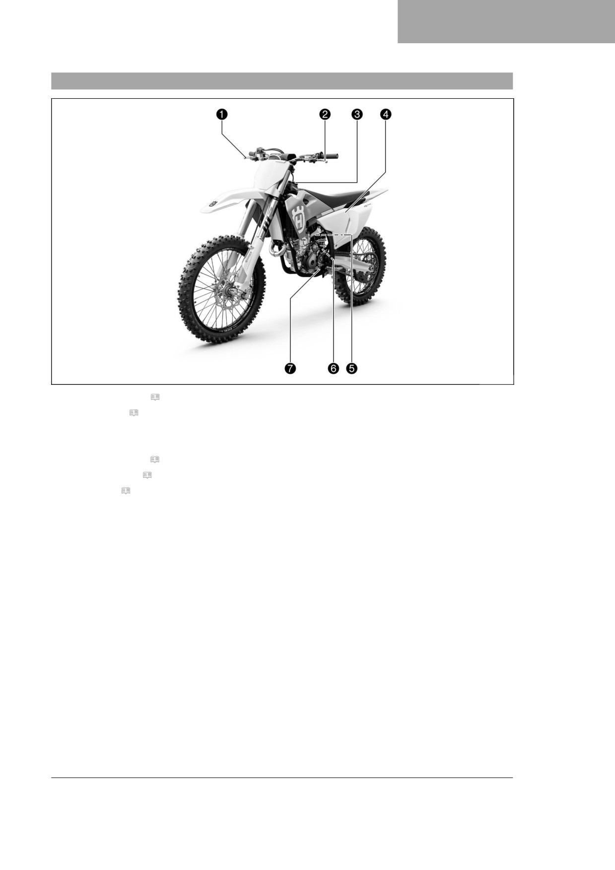
VIEW OF VEHICLE
4
4.1
View of vehicle, front left (example)
T04406-10
1 Handbrakelever(p.15)
2 Clutchlever(p.15)
3 Fueltankfillercap
4 Airfilterboxcover
5 Coldstartbutton(p.18)
6 Enginenumber(p.13)
7 Shiftlever(p.19)
11
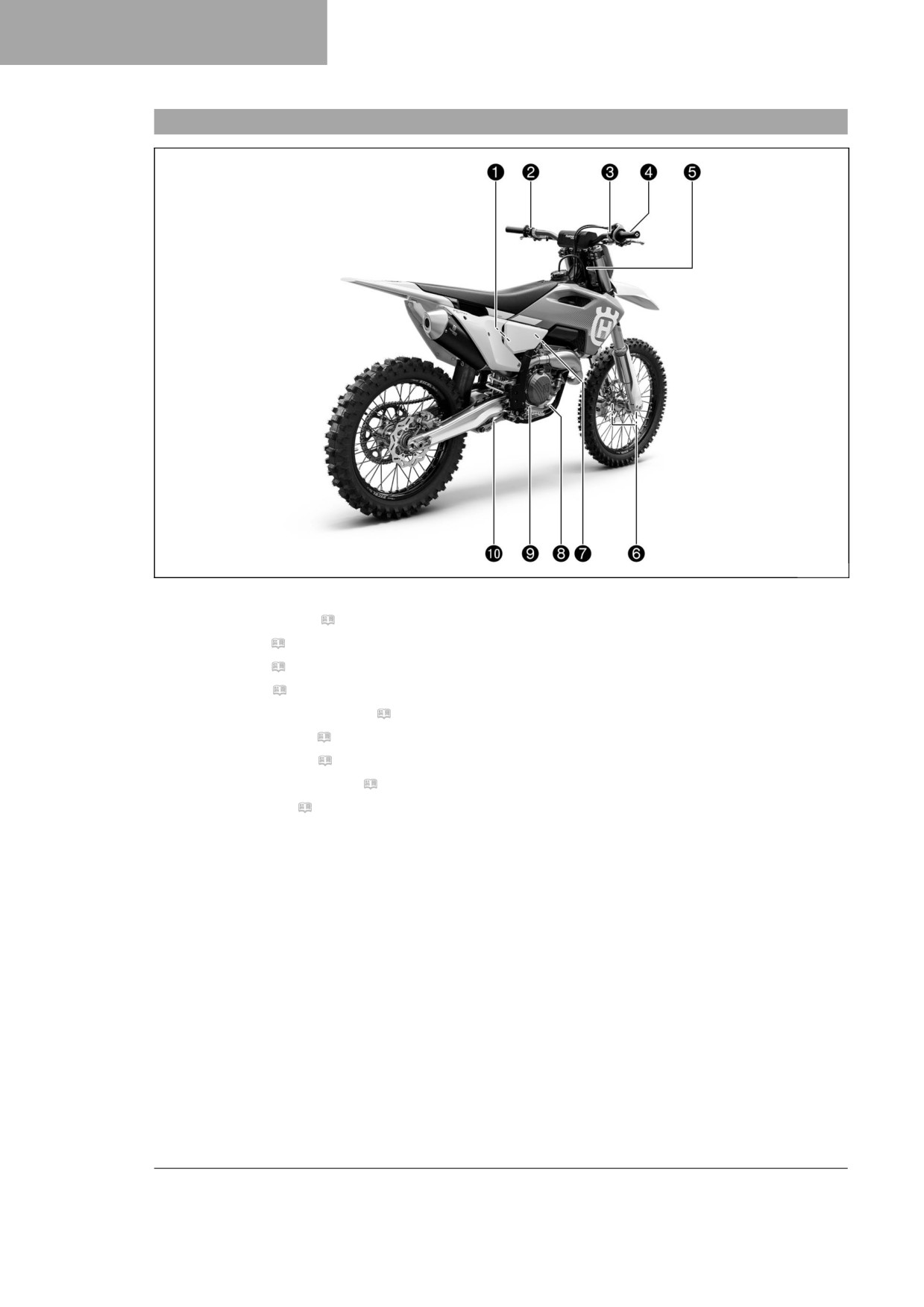
4
VIEW OF VEHICLE
4.2
View of vehicle, rear right (example)
T04407-10
1 Shockabsorbercompressionadjuster
2 Combinationswitch(p.16)
3 Stopbutton(p.15)
3 Startbutton(p.16)
4 Throttlegrip(p.15)
5 Vehicleidentificationnumber(p.13)
5 Steeringheadlabel(p.13)
6 Forkarticlenumber(p.13)
7 Idlespeedadjustingscrew(p.19)
8 Footbrakelever(p.20)
9 Engineoillevelviewer
bk Shockabsorberreboundadjuster
12
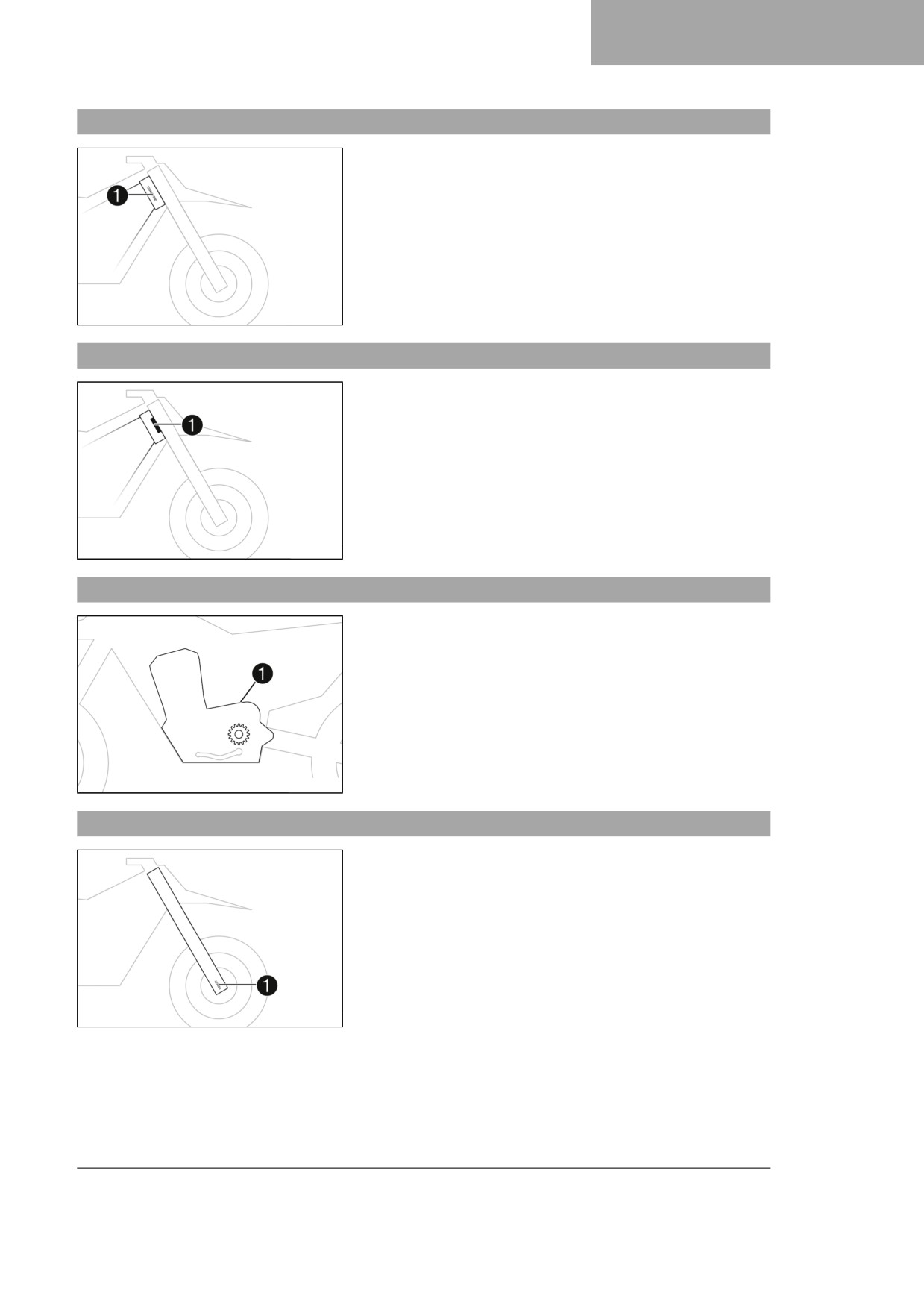
SERIAL NUMBERS
5
5.1
Vehicle identification number
The vehicle identification number 1 is stamped on the right side
of the steering head.
401945-10
5.2
Steering head label
The steering head label 1 is attached to the front of the steering
head.
401946-10
5.3
Engine number
Engine number 1 is embossed on the left side of the engine
above the engine sprocket.
H01047-10
5.4
Fork article number
The fork article number 1 is stamped on the inside of the axle
clamp.
401947-10
13

5
SERIAL NUMBERS
5.5
Shock absorber article number
The shock absorber article number 1 is stamped on the top of
the shock absorber.
F03756-10
14
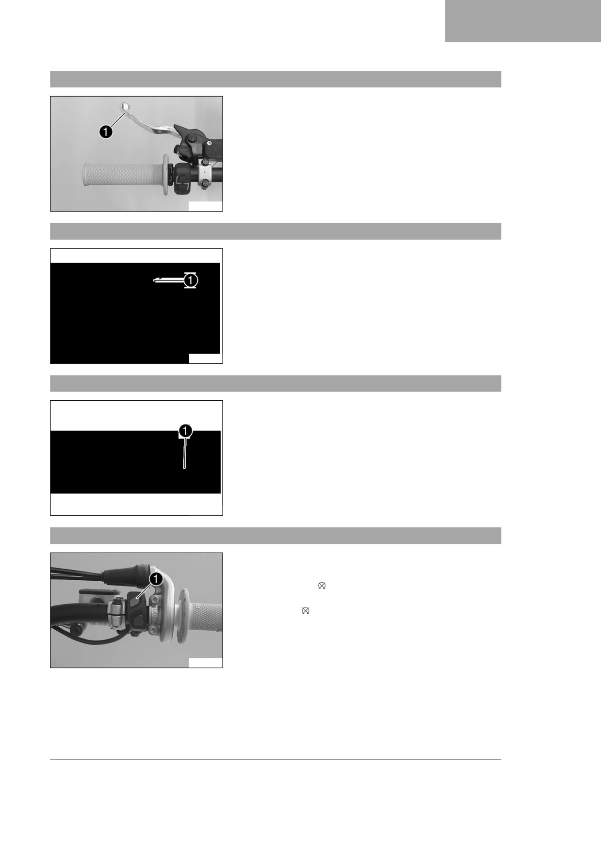
CONTROLS 6
6.1
Clutch lever
The clutch lever 1 is fitted on the left side of the handlebar.
The clutch is hydraulically operated and self-adjusting.
F03647-10
6.2
Hand brake lever
The hand brake lever 1 is located on the right side of the han-
dlebar.
The front brake is engaged using the hand brake lever.
J00077-10
6.3
Throttle grip
The throttle grip 1 is fitted on the right side of the handlebar.
J00076-10
6.4
Stop button
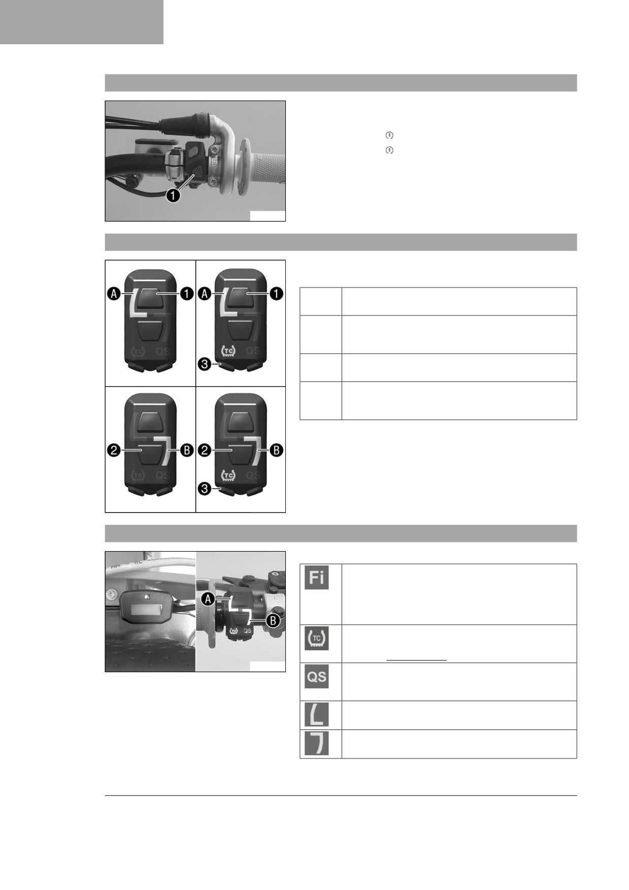
The stop button 1 is located on the right side of the handlebar.
Possible states
• The stop button is in the basic position - In this position,
the ignition circuit is closed and the engine can be started.
• Stop button pressed - In this position, the ignition circuit
is interrupted, a running engine stops, and a non-running
engine will not start.
F03650-11
15
6
CONTROLS
6.5
Start button
Start button 1 is fitted on the right side of the handlebar.
Possible states
• The start button is in the basic position
• The start button is pressed - In this position, the starter
motor is actuated.
F03650-10
6.6
Combination switch
The combination switch is fitted on the left side of the handlebar.
Possible states
1
STANDARD - STANDARD mapping is activated
when the indicator lamp A lights up.
1 TC
STANDARD with TC - STANDARD mapping with
traction control is activated when the indicator
lamp A and the TC indicator lamp light up.
2
ADVANCED - ADVANCED mapping is activated
when the indicator lamp B lights up.
2 TC
ADVANCED with TC - ADVANCED mapping with
traction control is activated when the indicator
lamp B and the TC indicator lamp light up.
The engine characteristic can be changed using button 1 and
button 2 on the combination switch.
Traction control can be activated using the TC button 3 on the
combination switch.
Launch control and the quickshifter can also be activated using
the combination switch.
F03761-10
6.7
Overview of indicator lights
Possible states
Malfunction indicator lamp lights up/flashes orange
- The OBD has detected a malfunction in the vehi-
cle electronics. The malfunction indicator lamp also
lights up if traction control is activated and the speed
limiter intervenes.
TC indicator lamp lights up orange - TC is enabled
or is currently intervening. The TC indicator lamp
flashes if launch control is activated.
F03758-10
QS indicator lamp lights up blue - The quickshifter
is activated. The QS indicator lamp flashes when the
quickshifter is being programmed.
Indicator lamp A lights up white
- STANDARD mapping is activated.
Indicator lamp B lights up green
- ADVANCED mapping is activated.
16
CONTROLS 6
6.8
Combination instrument
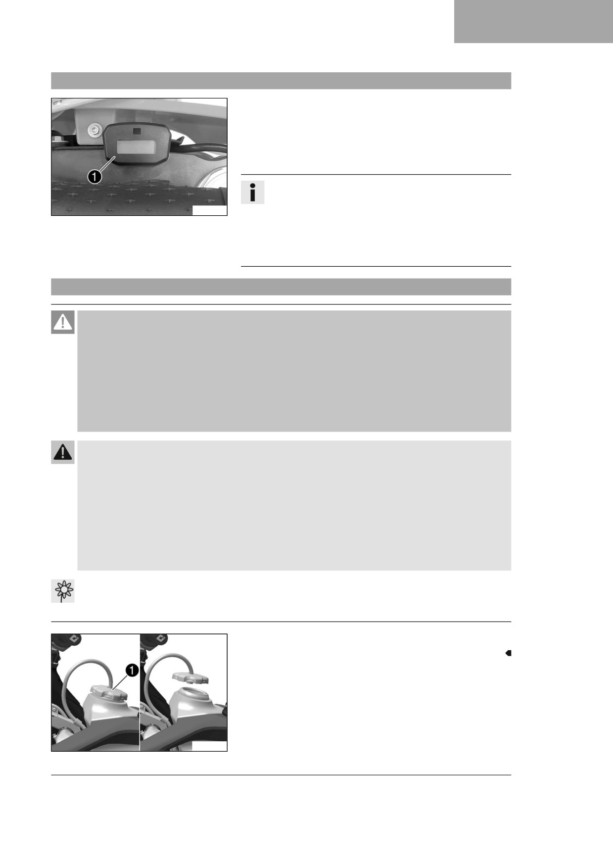
The combination instrument 1 is attached in front of the han-
dlebar.
The combination instrument shows the total number of operating
hours of the engine.
The operating hour counter begins counting when the engine is
started and stops when the engine is switched off.
Info
Nothing can be cleared or adjusted on the combination
F03765-10
instrument.
As soon as the diagnostics tool is connected, the service
hour counter starts running.
Before longer diagnostic sessions, unplug the service
hour counter behind the start number plate.
6.9
Opening fuel tank filler cap
Danger
Fire hazard Fuel is highly flammable.
The fuel in the fuel tank expands when warm and can escape if overfilled.
- Do not fuel the vehicle in the vicinity of open flames or lit cigarettes.
- Switch off the engine for refueling.
- Make sure that no fuel is spilled; particularly not on hot parts of the vehicle.
- If any fuel is spilled, wipe it off immediately.
- Observe the specifications for refueling.
Warning
Danger of poisoning Fuel is harmful to health.
- Avoid skin, eye and clothing contact with fuel.
- Immediately consult a doctor if you swallow fuel.
- Do not inhale fuel vapors.
- Rinse the affected area immediately with plenty of water in the event of contact with the skin.
- Rinse the eyes thoroughly with water, and consult a doctor in case of fuel contact with the eyes.
- Change your clothing if fuel spills on them.
- Keep fuels correctly in a suitable canister, and out of the reach of children.
Note
Environmental hazard Improper handling of fuel is a danger to the environment.
- Do not allow fuel to enter the groundwater, the soil, or the sewage system.
- Turn fuel tank filler cap 1 counterclockwise and lift it off.
A01172-10
17
6
CONTROLS
6.10
Closing the fuel tank filler cap
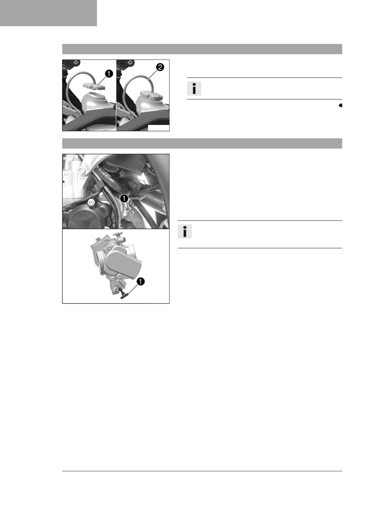
- Mount fuel tank filler cap 1 and turn it clockwise until the
fuel tank is tightly closed.
Info
Route fuel tank breather hose 2 without kinks.
A01173-10
6.11
Cold start button
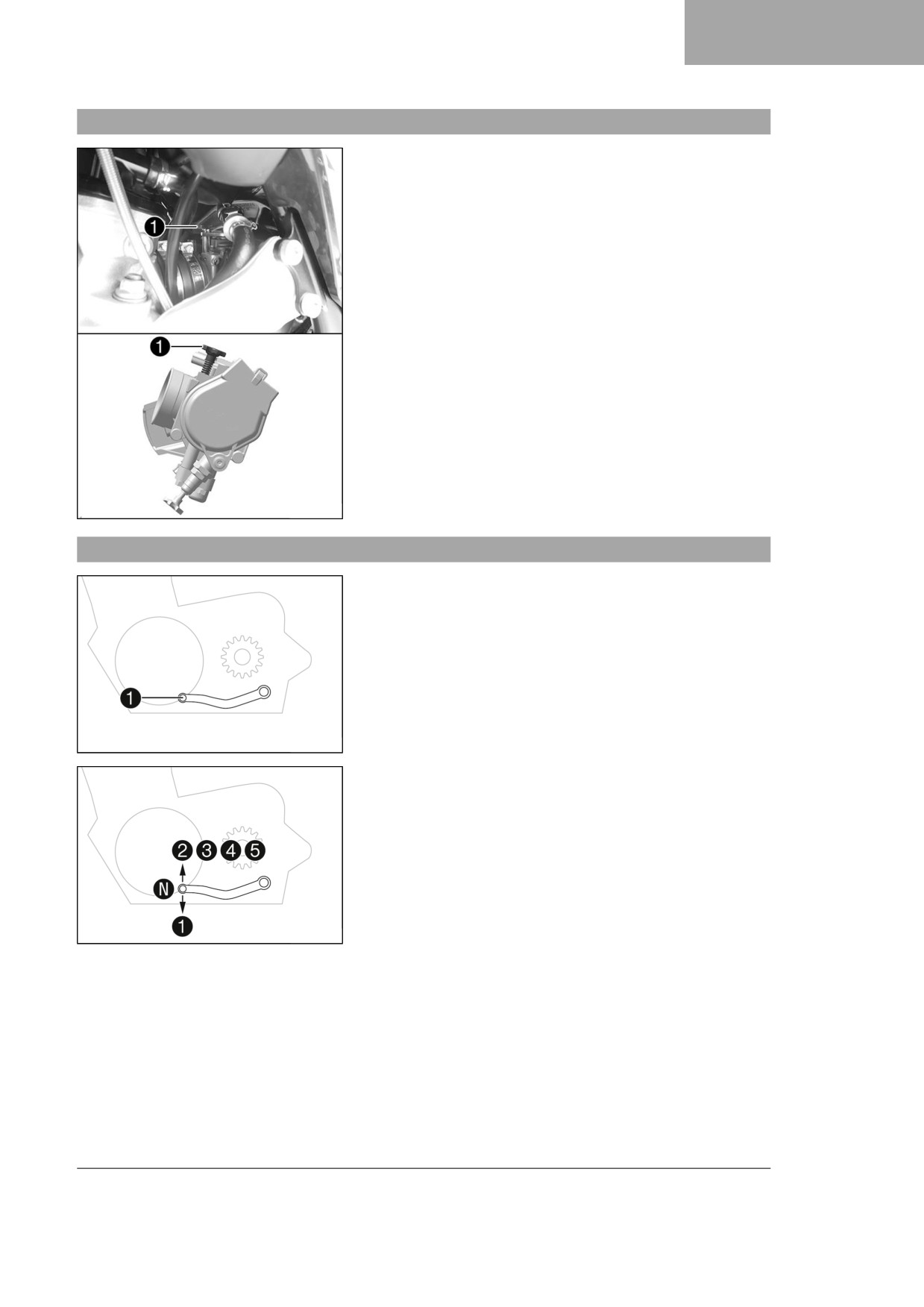
The cold start button 1 is fitted to the bottom of the throttle
valve body.
The electronic fuel injection system extends the injection time if
the engine is cold and the ambient temperature is low. To help
the engine burn the increased fuel quantity, it must be supplied
with additional oxygen by pushing the cold start button.
After briefly opening up the throttle and then releasing the throttle
grip again, or turning the throttle grip towards the front, the cold
start button returns to its original position.
Info
Check whether the cold start button has returned to its
basic position.
Possible states
• The cold start button is activated - The cold start button is
pushed in all the way.
• The cold start button is deactivated - The cold start button
is in its basic position.
A01062-10
18
CONTROLS 6
6.12
Idle speed adjusting screw
The idle setting of the throttle valve body substantially influences
the vehicle’s starting behavior, a stable idle speed, and the vehi-
cle’s response when the throttle is opened.
An engine with a correctly set idle speed is easier to start than an
engine with the idle speed set incorrectly.
The idle speed is adjusted using the idle speed adjusting
screw 1.
Increase the idle speed by turning the idle speed adjusting screw
clockwise.
Decrease the idle speed by turning the idle speed adjusting
screw counterclockwise.
A01063-10
6.13
Shift lever
Shift lever 1 is mounted on the left of the engine.
401950-10
The gear positions can be seen in the figure.
The neutral or idle position is between the first and second gears.
401950-13
19
6
CONTROLS
6.14
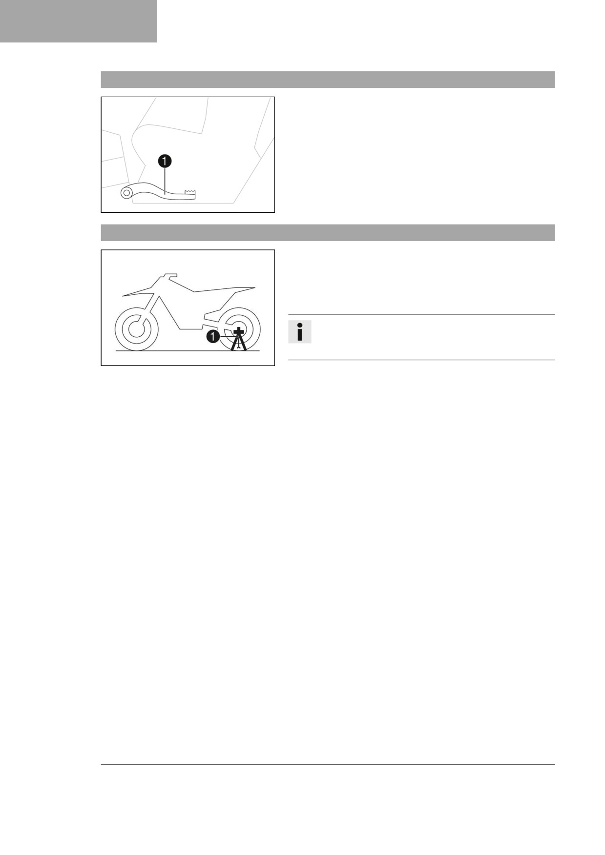
Foot brake lever
Foot brake lever 1 is located in front of the right footrest.
The foot brake lever is used to activate the rear brake.
401956-10
6.15
Plug-in stand
The holder for the plug-in stand 1 is the left side of the wheel
spindle.
The plug-in stand is used to park the motorcycle.
The plug-in stand is used as a fork locker when transporting the
motorcycle.
Info
Remove the plug-in stand before riding.
The tool can be attached to the plug-in stand holders.
H02629-10
20
PREPARING FOR USE
7
7.1
Advice on preparing for first use
Danger
Danger of accidents A rider who is not fit to ride poses a danger to him or herself and others.
- Do not operate the vehicle if you are not fit to ride due to alcohol, drugs or medication.
- Do not operate the vehicle if you are physically or mentally impaired.
Warning
Risk of injury Missing or poor protective clothing presents an increased safety risk.
- Wear appropriate protective clothing such as helmet, boots, gloves as well as trousers and a jacket
with protectors on all rides.
- Always wear protective clothing that is in good condition and meets the legal regulations.
Warning
Danger of crashing Different tire tread patterns on the front and rear wheel impair the handling char-
acteristic.
Different tire tread patterns can make the vehicle significantly more difficult to control.
- Make sure that only tires with a similar tire tread pattern are fitted to the front and rear wheel.
Warning
Danger of accidents An unadapted riding style impairs the handling characteristic.
- Adapt your riding speed to the road conditions and your riding ability.
Warning
Danger of accidents The vehicle is not designed to carry passengers.
- Do not ride with a passenger.
Warning
Danger of accidents The brake system fails in the event of overheating.
If the foot brake lever is not released, the brake linings drag continuously.
- Take your foot off the foot brake lever if you do not want to brake.
Warning
Danger of accidents Total weight and axle loads influence the handling characteristic.
- Do not exceed the maximum permissible overall weight or the axle loads.
Warning
Risk of injury People who act without authorization may not be familiar with the vehicle.
- Do not leave the vehicle unattended if the engine is running.
- Protect the vehicle against access by unauthorized persons.
Info
When using the motorcycle, remember that others may be disturbed by excessive noise.
-
Ensure that the pre-sale inspection work has been carried out by an authorized Husqvarna Motorcycles
workshop.
You will receive a delivery certificate when the vehicle is handed over.
-
Read the entire Owner's Manual before riding for the first time.
–
Get to know the controls.
–
Adjust basic position of the clutch lever. ( p. 79)
21
7
PREPARING FOR USE
- Adjust basic position of the hand brake lever. ( p. 82)
- Adjust the basic position of the foot brake lever.
(
p. 89)
– Adjust the basic position of the shift lever.
(
p. 116)
– Get used to the handling characteristic of the motorcycle on suitable terrain before undertaking a more
challenging ride.
Info
This vehicle is not approved for use on public roads.
When off road, it is recommended that you are accompanied by another person on another vehicle
so that you can help each other.
- Also, ride as slowly as possible and in a standing position to get a better feel for the motorcycle.
- Do not undertake any off-road trips that exceed your ability and experience.
- Hold the handlebar firmly with both hands and keep your feet on the footrests when riding.
- Do not carry the luggage.
- Do not exceed the maximum permissible weight and maximum permissible axle loads.
Guideline
Maximum permissible overall weight
335 kg (739 lb.)
Maximum permissible front axle load
145 kg (320 lb.)
Maximum permissible rear axle load
190 kg (419 lb.)
– Run the engine in. ( p. 22)
7.2
Running in the engine
– Do not exceed the specified engine speed and load during the running-in time.
Guideline
Maximum engine speed
During the first operating hour
7,000 rpm
Maximum engine performance
During the first 3 operating hours
≤ 75 %
– Avoid fully opening the throttle.
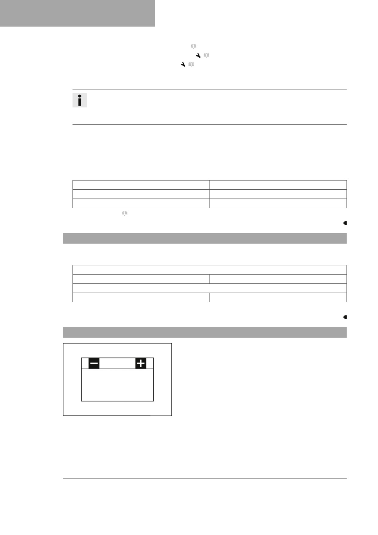
7.3
Starting power of lithium-ion batteries at low temperatures
Lithium-ion batteries are far lighter than lead batteries, have a
low self-discharge rate, and have more starting power at temper-
atures over 6 °C (43 °F).
Several attempts to start may be required. Press the start button
for 5 seconds, and wait 15 seconds between attempts. At low
temperatures, wait for 30 seconds. The pauses are necessary
so that the heat created can distribute through the lithium-ion
battery and the lithium-ion battery is not damaged.
The starting power increases as the battery warms up.
Always make sure the lithium-ion battery is charged to that there
402555-01
is enough power to spare for starting at low temperatures.
After 6 unsuccessful starting attempts, do not try again, and
check the vehicle for other malfunctions instead.
22
PREPARING FOR USE
7
7.4
Preparing the vehicle for difficult operating conditions
Info
Use of the vehicle under difficult conditions, such as on sand or on wet and muddy surfaces, can result
in significantly increased wear of components, such as the drive train, brake system, or suspension
components. For this reason, it may be necessary to inspect or replace parts before the next scheduled
service.
- Clean the air filter and air filter box.
(
p. 65)
Info
Check the air filter approx. every 30 minutes.
- Check the electrical connector for humidity and corrosion and to ensure it is firmly seated.
» If humidity, corrosion, or damage is found:
- Clean and dry the connector, or change it if necessary.
Difficult operating conditions are:
- Rides on dry sand. ( p. 23)
- Rides on wet sand. ( p. 24)
- Rides on wet and muddy circuits. ( p. 24)
- Rides at high temperatures or slow riding. ( p. 25)
- Riding at low temperatures and in snow. ( p. 25)
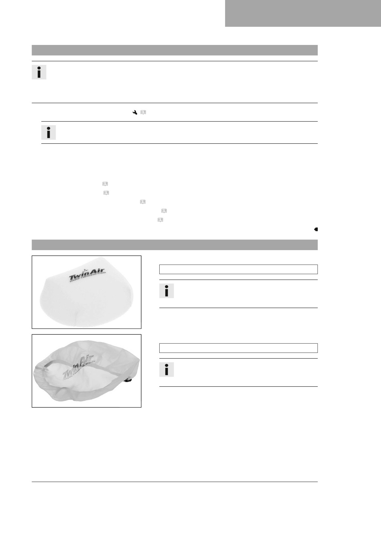
7.5
Preparing the vehicle for rides on dry sand
- Mount the air filter dust cover.
Air filter dust cover (A46009620000)
Info
Observe the fitting instructions for Husqvarna Motor-
cycles technical accessories.
F03669-01
- Mount the air filter sand cover.
Air filter sand cover (A46006922000)
Info
Observe the fitting instructions for Husqvarna Motor-
cycles technical accessories.
F03670-01
23
7
PREPARING FOR USE
- Clean the chain.
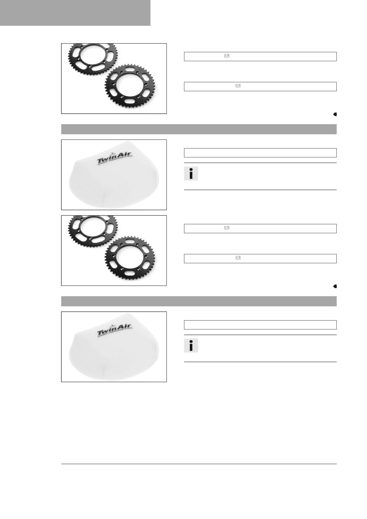
Chain cleaner ( p. 142)
- Mount the steel sprocket.
- Grease the chain.
Universal oil spray ( p. 143)
- Clean the radiator fins.
- Straighten the bent radiator fins carefully.
600868-01
7.6
Preparing the vehicle for rides on wet sand
- Mount the air filter rain cover.
Air filter rain cover (A46006921000)
Info
Observe the fitting instructions for Husqvarna Motor-
cycles technical accessories.
F03669-01
- Clean the chain.
Chain cleaner ( p. 142)
- Mount the steel sprocket.
- Grease the chain.
Universal oil spray ( p. 143)
- Clean the radiator fins.
- Straighten the bent radiator fins carefully.
600868-01
7.7
Preparing the vehicle for rides on wet and muddy circuits
- Mount the air filter rain cover.
Air filter rain cover (A46006921000)
Info
Observe the fitting instructions for Husqvarna Motor-
cycles technical accessories.
F03669-01
24
PREPARING FOR USE
7
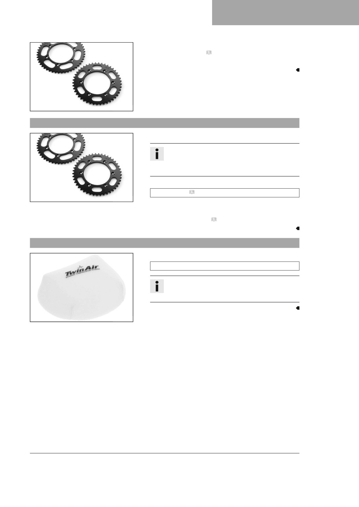
– Mount the steel sprocket.
- Clean the motorcycle. ( p. 122)
- Straighten the bent radiator fins carefully.
600868-01
7.8
Preparing vehicle for high temperatures or slow riding
- Adjust the secondary drive to the road conditions.
Info
The engine oil heats up quickly when the clutch is
operated frequently due to an excessively high sec-
ondary ratio.
- Clean the chain.
Chain cleaner ( p. 142)
600868-01
- Clean the radiator fins.
- Straighten bent radiator fins carefully.
- Check the coolant level. ( p. 108)
7.9
Preparing the vehicle for low temperatures or snow
- Mount the air filter rain cover.
Air filter rain cover (A46006921000)
Info
Observe the fitting instructions for Husqvarna Motor-
cycles technical accessories.
F03669-01
25
8
RIDING INSTRUCTIONS
8.1
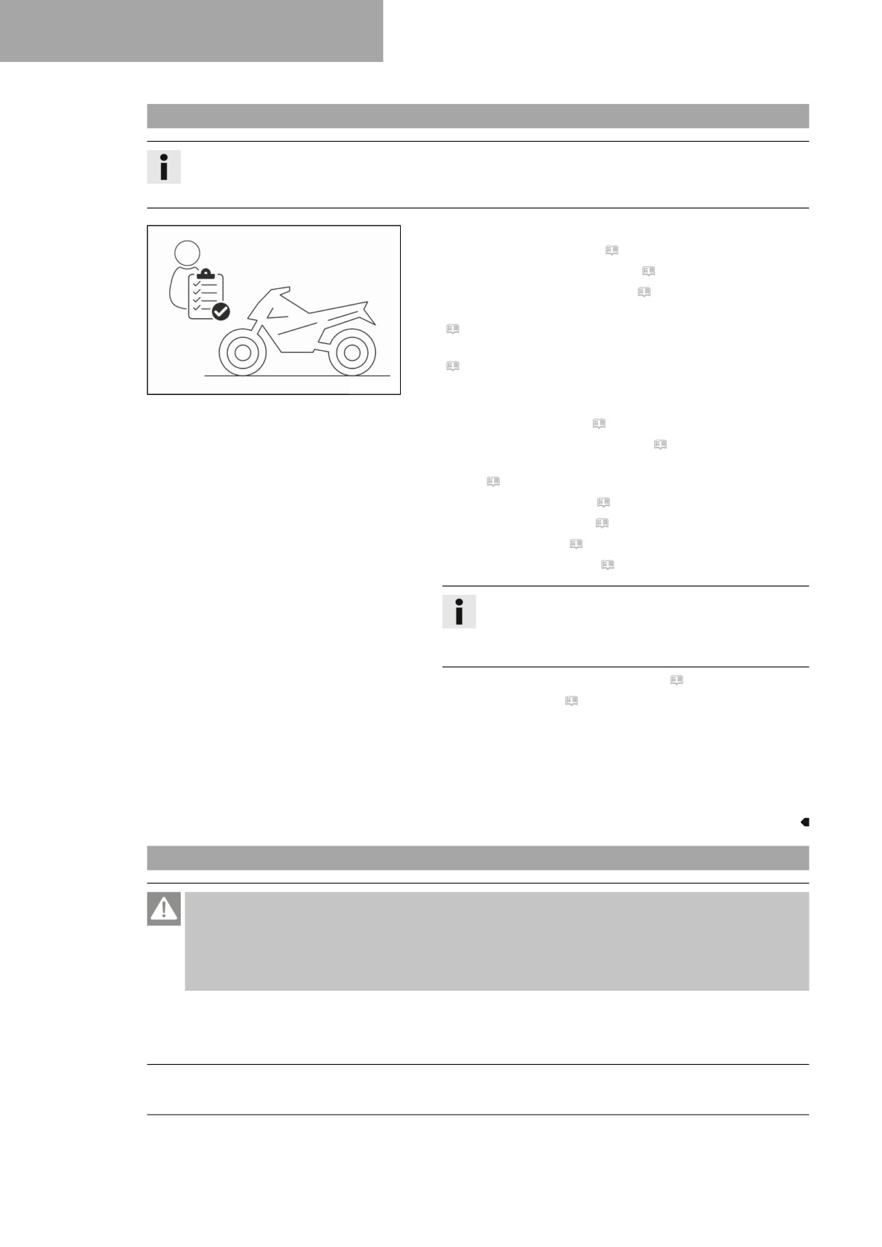
Checks and maintenance measures when preparing for use
Info
Before every trip, check the condition of the vehicle and ensure that it is safe to operate.
The vehicle must be in perfect technical condition when it is being operated.
-
Check that the electrical system is functioning properly.
–
Check the engine oil level. ( p. 118)
–
Check the front brake fluid level. ( p. 83)
–
Check the rear brake fluid level. ( p. 89)
–
Check that the brake linings of the front brake are secured.
(
p. 85)
–
Check that the brake linings of the rear brake are secured.
(
p. 91)
H02217-01
-
Check the function, condition, and free travel of the brake
system.
-
Check the coolant level. ( p. 108)
–
Check for chain dirt accumulation. ( p. 72)
–
Check the chain, rear sprocket, engine sprocket, and chain
guide. ( p. 75)
-
Check the chain tension. ( p. 73)
–
Check the tire condition. ( p. 99)
–
Check tire pressure. ( p. 99)
–
Check the spoke tension. ( p. 100)
Info
The spoke tension must be checked regularly as
incorrect spoke tension will strongly impair riding
safety.
-
Clean the dust boots of the fork legs. ( p. 50)
–
Bleed the fork legs. ( p. 50)
–
Check the air filter and clean if necessary.
–
Check the settings of all controls and ensure that they can be
operated smoothly.
-
Check all screws, nuts, and hose clips regularly for tightness.
–
Check the fuel level.
8.2
Starting the vehicle
Danger
Danger of poisoning Exhaust gases are toxic and inhaling them may result in unconsciousness and
death.
- Always make sure there is sufficient ventilation when running the engine.
- Use effective exhaust extraction when starting or running the engine in an enclosed space.
Note
Engine damage High revving speed with a cold engine negatively impacts the lifespan of the engine.
- Always run the engine warm at a low speed.
26
RIDING INSTRUCTIONS
8
– Remove plug-in stand 1.
- Shift the transmission to the neutral position.
H02629-10
Condition
Ambient temperature: < 20 °C (< 68 °F)
- Push the cold start button in all the way.
- Press start button
Info
Press the start button for a maximum of 5 sec-
onds. Wait for 15 seconds before a further attempt
at starting.
400733-01
At low temperatures, wait for 30 seconds.
At temperatures below 6 °C (43 °F), several
attempts at starting may be necessary to warm-up
the lithium-ion battery and thereby increase the
starting power.
After 6 unsuccessful starting attempts, do not try
again, and check the vehicle for other malfunc-
tions instead.
During the starting process, the malfunction indi-
cator lamp lights up.
8.3
Activating launch control
Info
The launch control helps the rider to generate optimum motorcycle acceleration at the beginning of a
race. The maximum speed of the engine with the throttle valve fully opened (full throttle) is reduced.
After the start, it is gradually increased up to the maximum engine speed. The clutch must be operated
exactly as it would be without launch control activated.
Condition
The motorcycle is stationary.
The engine is running at idle speed.
The transmission is in neutral.
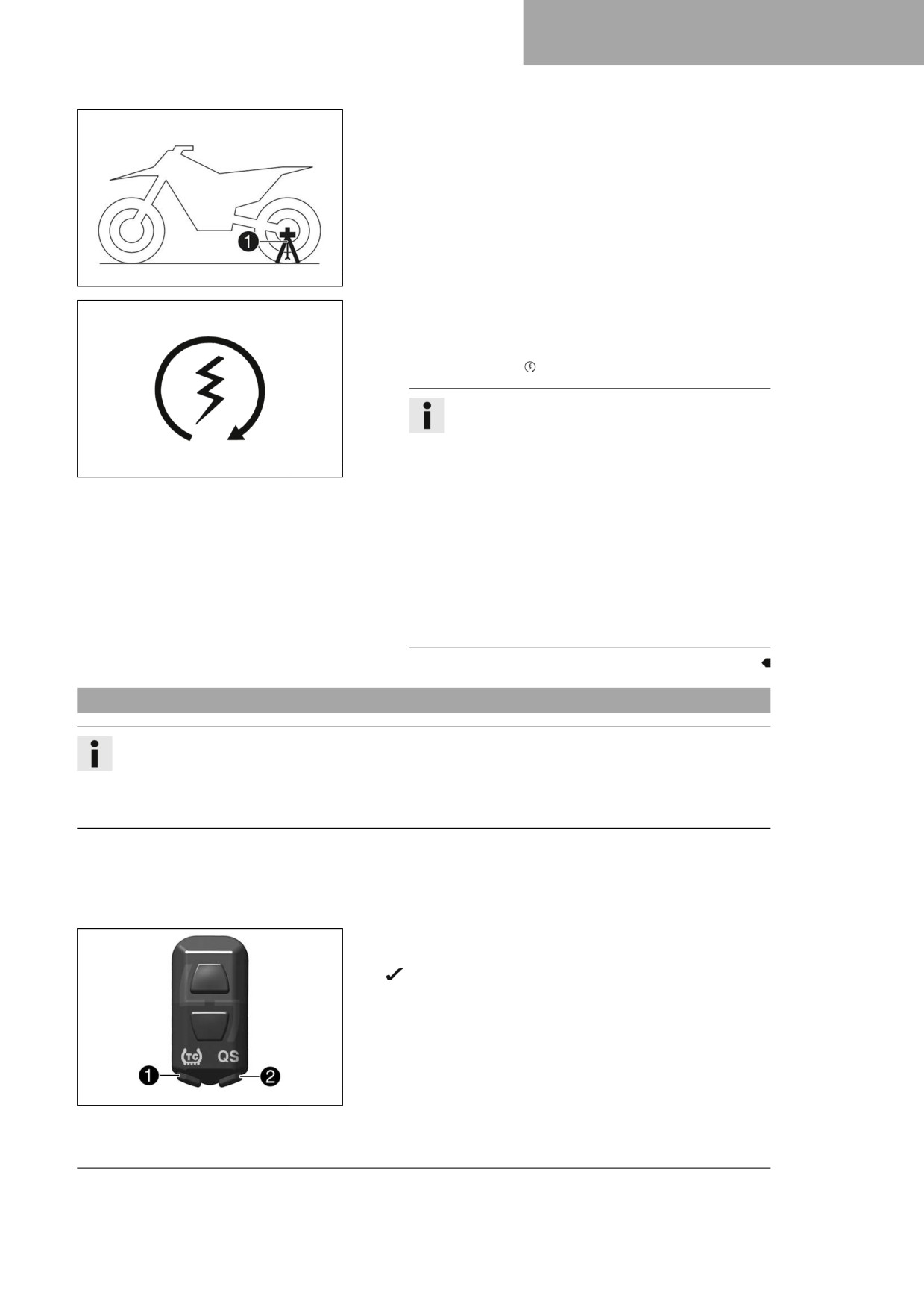
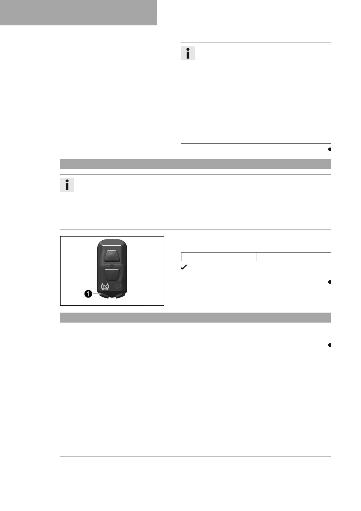
- Press and hold the TC button 1 and the QS button 2
simultaneously.
The TC indicator lamp and the QS indicator lamp flash
when launch control is activated.
F03760-10
27
8
RIDING INSTRUCTIONS
Info
The launch control is deactivated automatically for a
few seconds after the vehicle has started.
Launch control is also deactivated in the following
cases: if the throttle valve is closed more than 1/3 of
the way after full throttle, and/or if there is no start
within 3 minutes.
For safety reasons, the engine must be switched off
for at least 10 seconds before the launch control can
be activated again, regardless of whether the vehicle
has been started or not.
If the engine has already been running for some time,
the engine must first be restarted before the launch
control can be activated.
8.4
Activating traction control
Info
The traction control reduces excessive slip on the rear wheel in favor of more control and propulsion,
particularly in wet conditions.
When traction control is switched off, the rear wheel may spin more during high acceleration and on sur-
faces with low grip.
Traction control can be switched on or off during the ride.
The setting most recently selected is activated again when restarting.
- Press the TC button 1 to switch traction control on or off.
Guideline
Engine speed
≤ 4,000 rpm
The TC indicator lamp lights up when traction control is
activated.
F03760-11
8.5
Starting off
– Pull the clutch lever, engage 1st gear, release the clutch lever slowly and simultaneously open the throttle
carefully.
28
RIDING INSTRUCTIONS
8
8.6
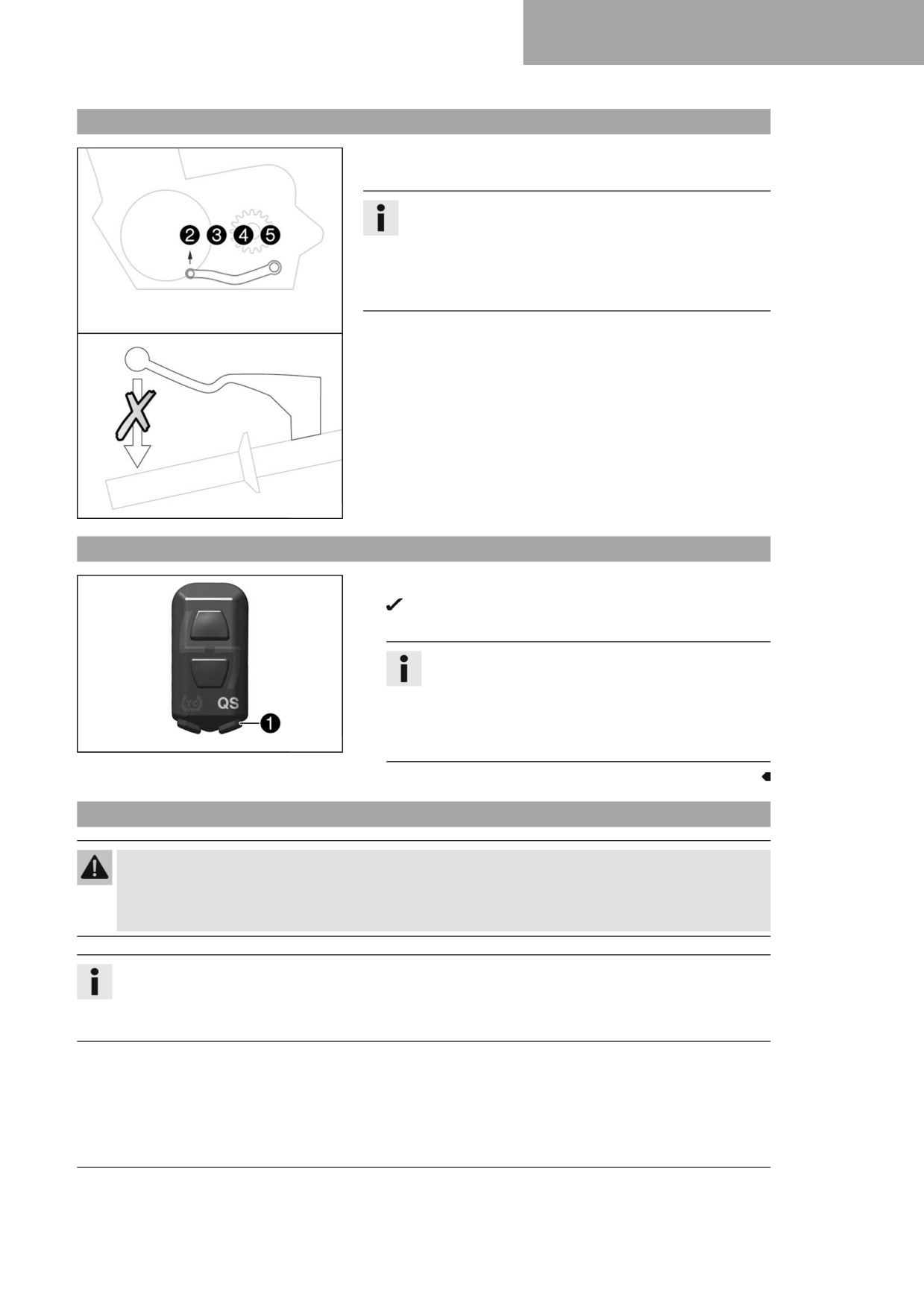
Quickshifter
When the quickshifter is activated, you can shift up without actu-
ating the clutch.
Info
The quickshifter is not activated when shifting up from
first to second gear, and the clutch lever must be used
when shifting up instead.
Even if the quickshifter is activated, you need to use the
clutch lever to shift down.
Because there is no need to close the throttle grip, uninterrupted
gear shifts are possible.
The quickshifter uses the shifter shaft position to check whether
or not a shift should be initiated, and sends a corresponding sig-
nal to the engine control.
If the quickshifter is deactivated, the clutch needs to be actuated
in the normal way for each shift.
F03643-10
8.7
Activating the quickshifter
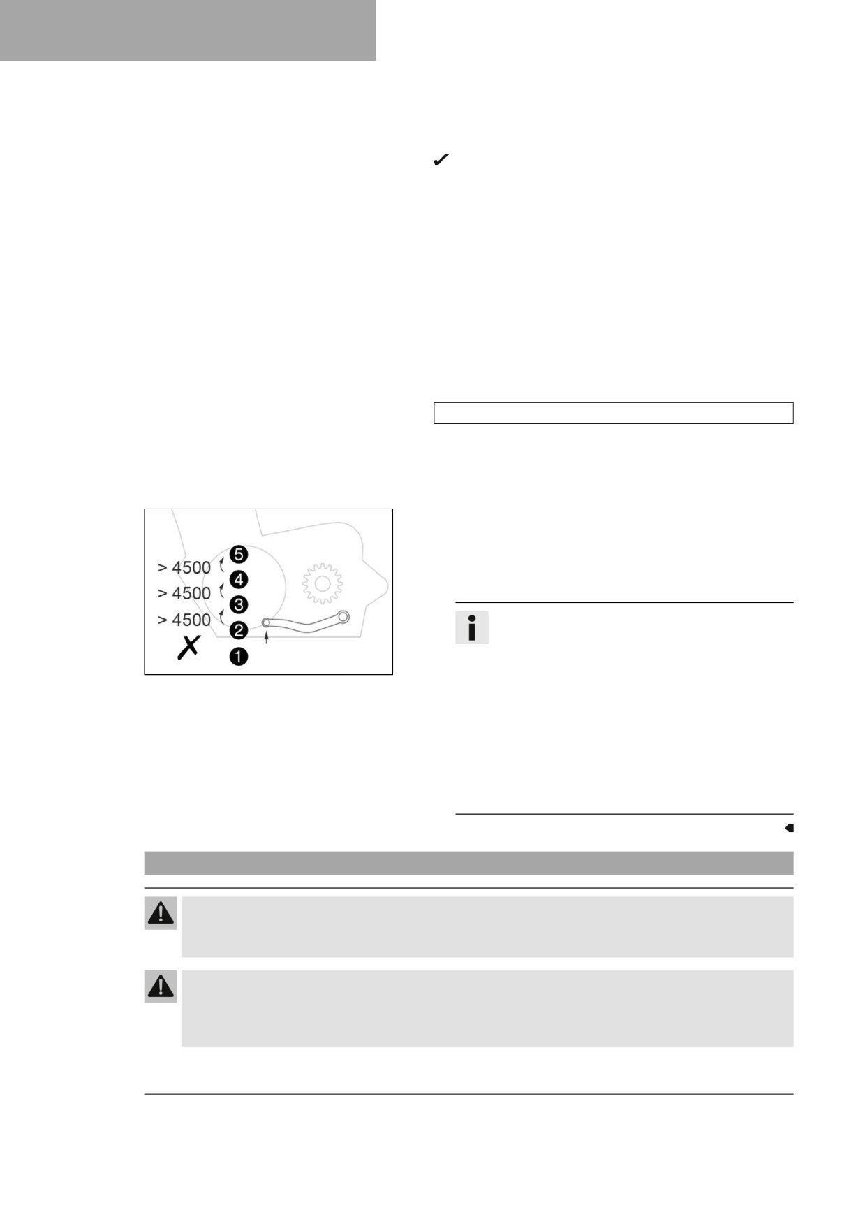
- Press the QS button 1 to switch the quickshifter on or off.
The QS indicator lamp lights up when the quickshifter is
activated.
Info
The quickshifter is not activated when shifting up from
first to second gear, and the clutch lever must be used
when shifting up instead.
Even if the quickshifter is activated, you need to use
F03760-12
the clutch lever to shift down.
8.8
Shifting, riding
Warning
Danger of accidents If you change down at high engine speed, the rear wheel blocks and the engine
races.
- Do not change into a low gear at high engine speed.
Info
If unusual noises occur while riding, stop immediately, switch off the engine, and contact an authorized
Husqvarna Motorcycles workshop.
First-gear is used for starting off and for steep inclines.
- Shift into a higher gear when conditions allow (incline, road
situation, etc.). To do so, release the throttle while simultane-
ously pulling the clutch lever, shift into the next gear, release
the clutch lever and open the throttle.
29
8
RIDING INSTRUCTIONS
- If the cold start button was pushed while starting, open the
throttle briefly and release the throttle grip or turn the throttle
grip forward.
The cold start button goes to the basic position.
- After reaching maximum speed by fully opening the throt-
tle grip, turn the throttle back so it is ¾ open. This will barely
reduce the speed, but fuel consumption will be considerably
lower.
- Only open the throttle as much as the engine can handle -
abrupt throttle grip opening increases fuel consumption.
- To shift down, apply the brakes and close the throttle at the
same time.
- Pull the clutch lever and shift into a lower gear, release the
clutch lever slowly, and either open the throttle or shift again.
- Switch off the engine if you are likely to be running at idle
speed or stationary for a long time.
Guideline
≥ 1 min
- Avoid frequent or lengthy slipping of the clutch. This causes
the engine oil, engine and cooling system to heat up.
- Ride at a low engine speed instead of at a high engine speed
with a slipping clutch.
Condition
Quickshifter activated.
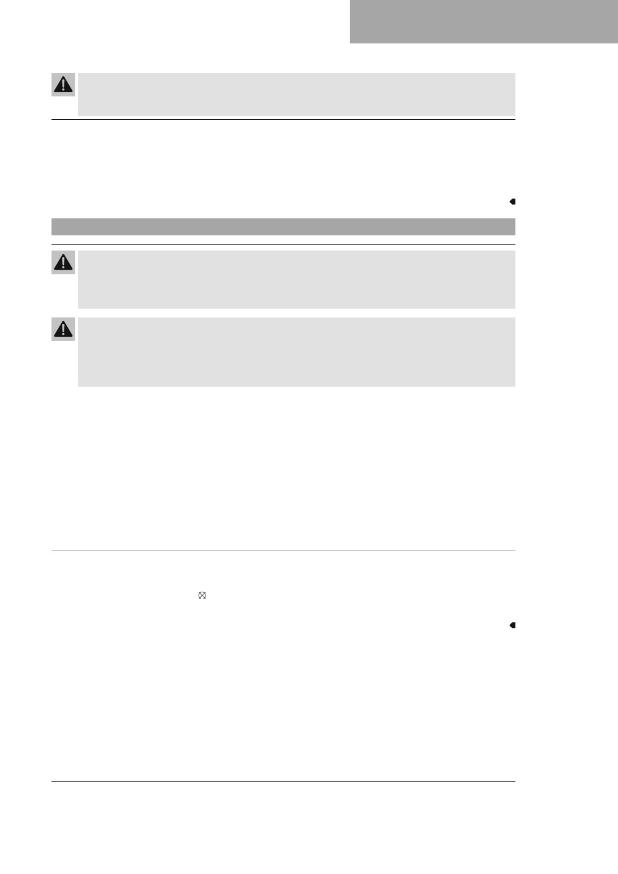
- If the quickshifter is activated, you can shift up in the
engine speed range shown without pulling the clutch
lever.
Info
The quickshifter is not activated when shifting
up from first to second gear, and the clutch lever
F03642-10
must be used when shifting up instead.
The minimum engine speed before shifting up in
revolutions per minute is shown in the figure.
Pull the shift lever to the stop quickly without
changing the throttle twist grip position.
Even if the quickshifter is activated, you need to
use the clutch lever to shift down.
If the shifting performance of the quickshifter
starts to decrease, it must be reprogrammed.
8.9
Applying the brakes
Warning
Danger of accidents Excessively forceful application of the brakes blocks the wheels.
- Adjust application of the brakes to the respective riding situation and riding surface conditions.
Warning
Danger of accidents A spongy pressure point on the front or rear brake reduces braking efficiency.
- Check the brake system and do not continue riding until the problem is eliminated. (Your authorized
Husqvarna Motorcycles workshop will be glad to help.)
30
RIDING INSTRUCTIONS
8
Warning
Danger of accidents Moisture and dirt impair the brake system.
- Brake carefully several times to dry out and remove dirt from the brake linings and the brake discs.
- On sandy, wet, or slippery surfaces, use mostly the rear brake.
- Always finish braking before you go into a bend. Shift down to a lower gear appropriate to your speed.
- Use the braking effect of the engine on long downhill stretches. Shift back one or two gears, but do not
overrev the engine when doing so. This means that significantly less braking is required and the brake sys-
tem does not overheat.
8.10
Stopping, parking
Warning
Risk of injury People who act without authorization may not be familiar with the vehicle.
- Do not leave the vehicle unattended if the engine is running.
- Protect the vehicle against access by unauthorized persons.
Warning
Danger of burns Some vehicle components become hot when the vehicle is operated.
- Do not touch any parts such as the exhaust system, radiator, engine, damper, or brake system
before the vehicle parts have cooled down.
- Let the vehicle parts cool down before you perform any work on the vehicle.
Note
Material damage The vehicle may be damaged by incorrect procedure when parking.
Significant damage may be caused if the vehicle rolls away or falls over.
The components for parking the vehicle are designed only for the weight of the vehicle.
- Park the vehicle on a firm and level surface.
- Ensure that nobody sits on the vehicle when the vehicle is parked on a stand.
Note
Fire hazard Hot vehicle components pose a fire hazard and explosion risk.
- Do not park the vehicle near to materials which are highly flammable or explosive.
- Allow the vehicle to cool down before covering it.
- Apply the brakes on the motorcycle.
- Shift the transmission to the neutral position.
- Press and hold the stop button while the engine is idling until the engine stops.
- Park the motorcycle on firm ground.
31
8
RIDING INSTRUCTIONS
8.11
Transporting
Note
Danger of damage The parked vehicle can roll away or fall over.
- Park the vehicle on a firm and level surface.
Note
Fire hazard Hot vehicle components pose a fire hazard and explosion risk.
- Do not park the vehicle near to materials which are highly flammable or explosive.
- Allow the vehicle to cool down before covering it.
- Switch off the engine.
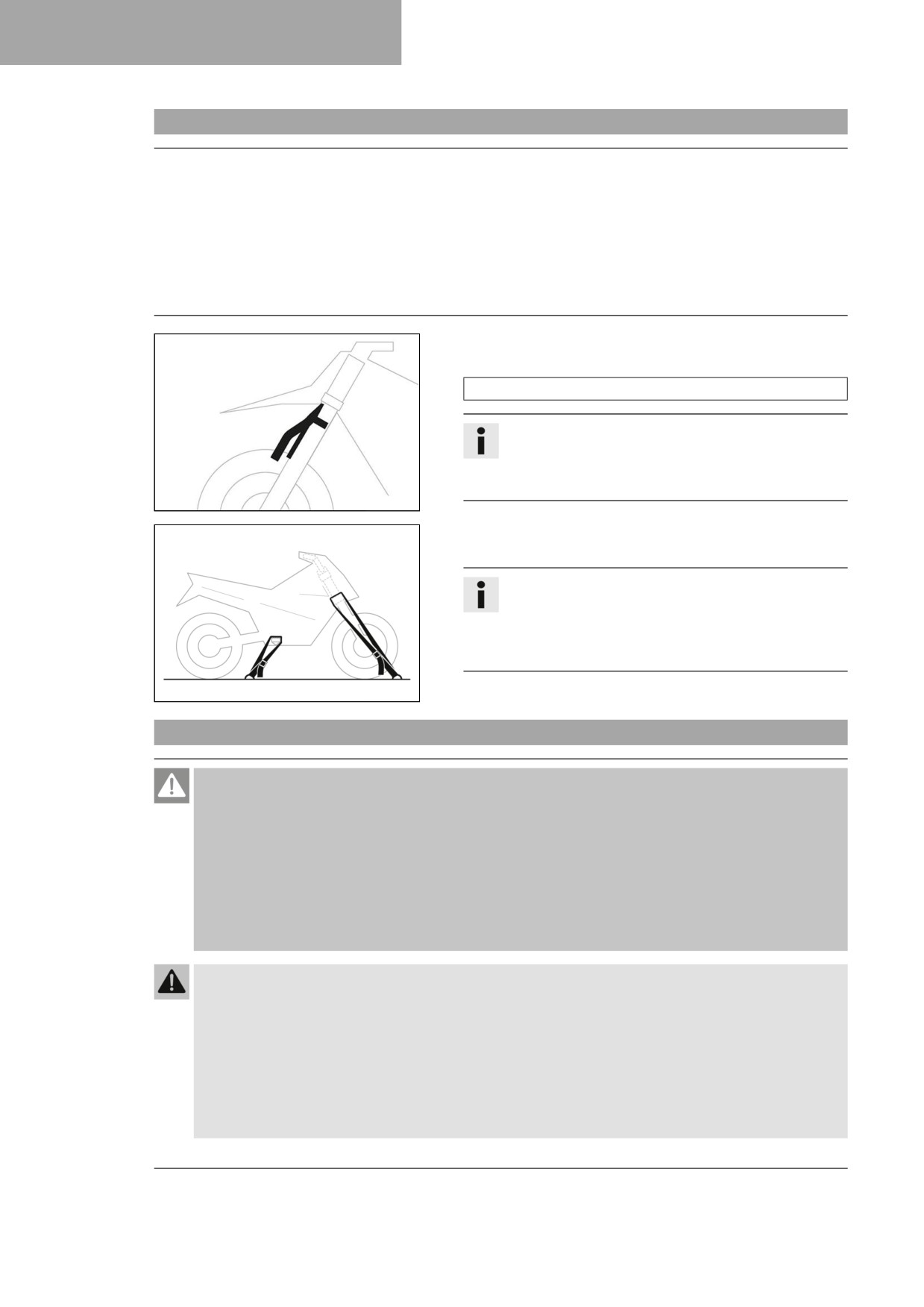
- Mount plug-in stand on the fork legs.
Plug-in stand (A46029094000)
Info
The plug-in stand is included.
Make sure the brake line runs in front of the plug-in
stand and does not become wedged.
H02628-01
- Use tension belts or other suitable devices to secure the
motorcycle against falling over or rolling away.
Info
Only tighten the tension belts to the point that the
plug-in stand is in contact with the fender and tires.
Pay attention to the alignment of the plug-in stand to
the fender.
401475-01
8.12
Refueling
Danger
Fire hazard Fuel is highly flammable.
The fuel in the fuel tank expands when warm and can escape if overfilled.
- Do not fuel the vehicle in the vicinity of open flames or lit cigarettes.
- Switch off the engine for refueling.
- Make sure that no fuel is spilled; particularly not on hot parts of the vehicle.
- If any fuel is spilled, wipe it off immediately.
- Observe the specifications for refueling.
Warning
Danger of poisoning Fuel is harmful to health.
- Avoid skin, eye and clothing contact with fuel.
- Immediately consult a doctor if you swallow fuel.
- Do not inhale fuel vapors.
- Rinse the affected area immediately with plenty of water in the event of contact with the skin.
- Rinse the eyes thoroughly with water, and consult a doctor in case of fuel contact with the eyes.
- Change your clothing if fuel spills on them.
32
RIDING INSTRUCTIONS
8
Note
Material damage Inadequate fuel quality causes the fuel filter to quickly become clogged.
In some countries and regions, the available fuel quality and cleanliness may not be sufficient. This will result
in problems with the fuel system.
- Refuel only with clean fuel that meets the specified standards. (Your authorized Husqvarna Motorcycles
workshop will be glad to help.)
Note
Environmental hazard Improper handling of fuel is a danger to the environment.
- Do not allow fuel to enter the groundwater, the soil, or the sewage system.
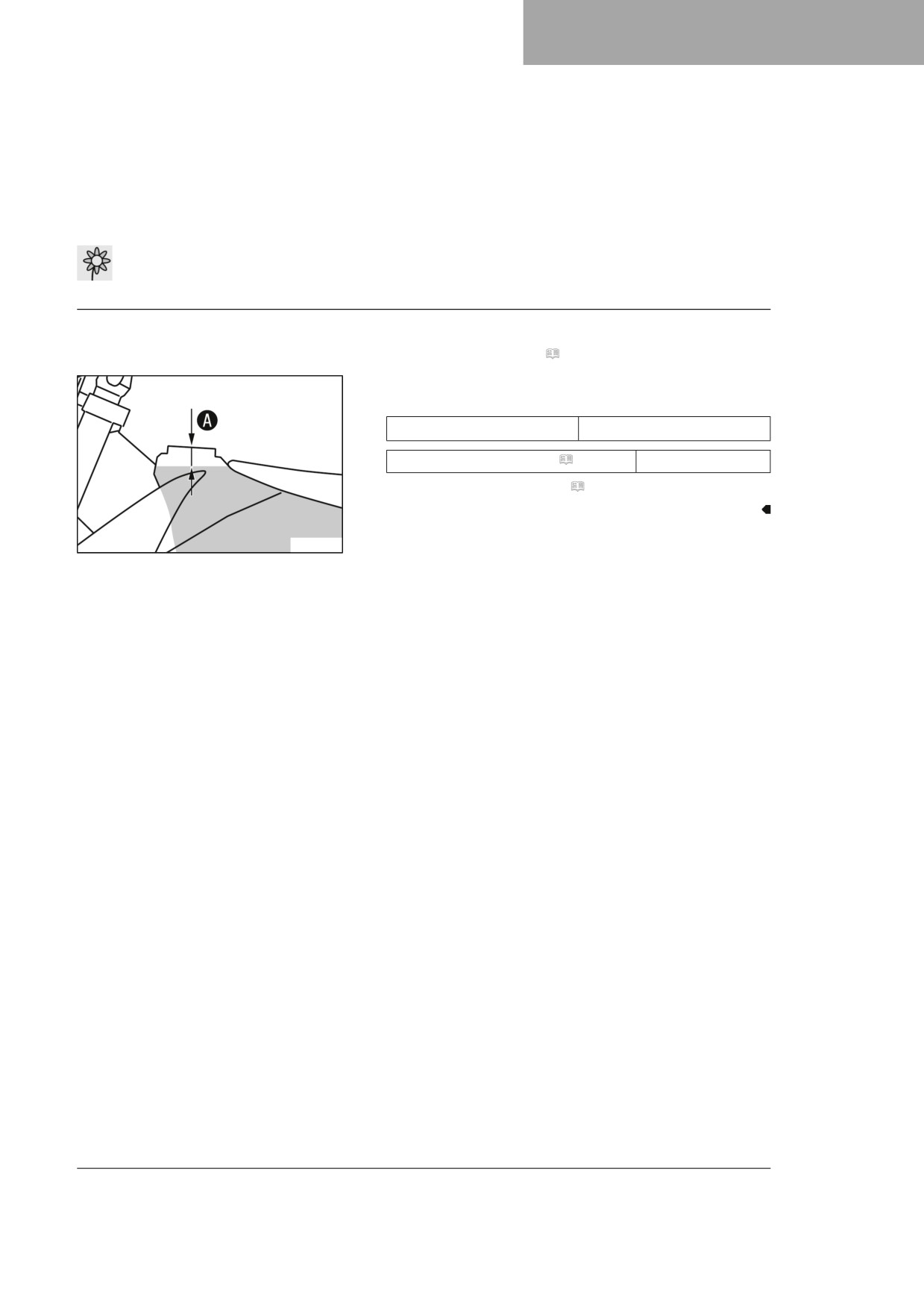
- Switch off the engine.
- Open fuel tank filler cap. ( p. 17)
- Fill the fuel tank with fuel up to level A.
Guideline
35 mm (1.38 in)
Dimension A
Super unleaded (ROZ 95) ( p. 141)
7.2 l (1.9 US gal)
– Close the fuel tank filler cap. ( p. 18)
401522-10
33
9
SERVICE SCHEDULE
9.1
Additional information
Any further work that results from the service work must be ordered separately and invoiced separately.
Different service intervals may apply in your country, depending on the local operating conditions.
If the vehicle is used in particularly harsh conditions such as heavy rain, mud, sand, snow, extreme tempera-
tures, frequent full load etc., shorter service intervals than those in the table may be necessary.
Individual service intervals and scopes may change in the course of technical developments. The most up-
to-date service schedule can always be found on Husqvarna Motorcycles Dealer.net. Your authorized Husq-
varna Motorcycles dealer will be glad to advise you.
9.2
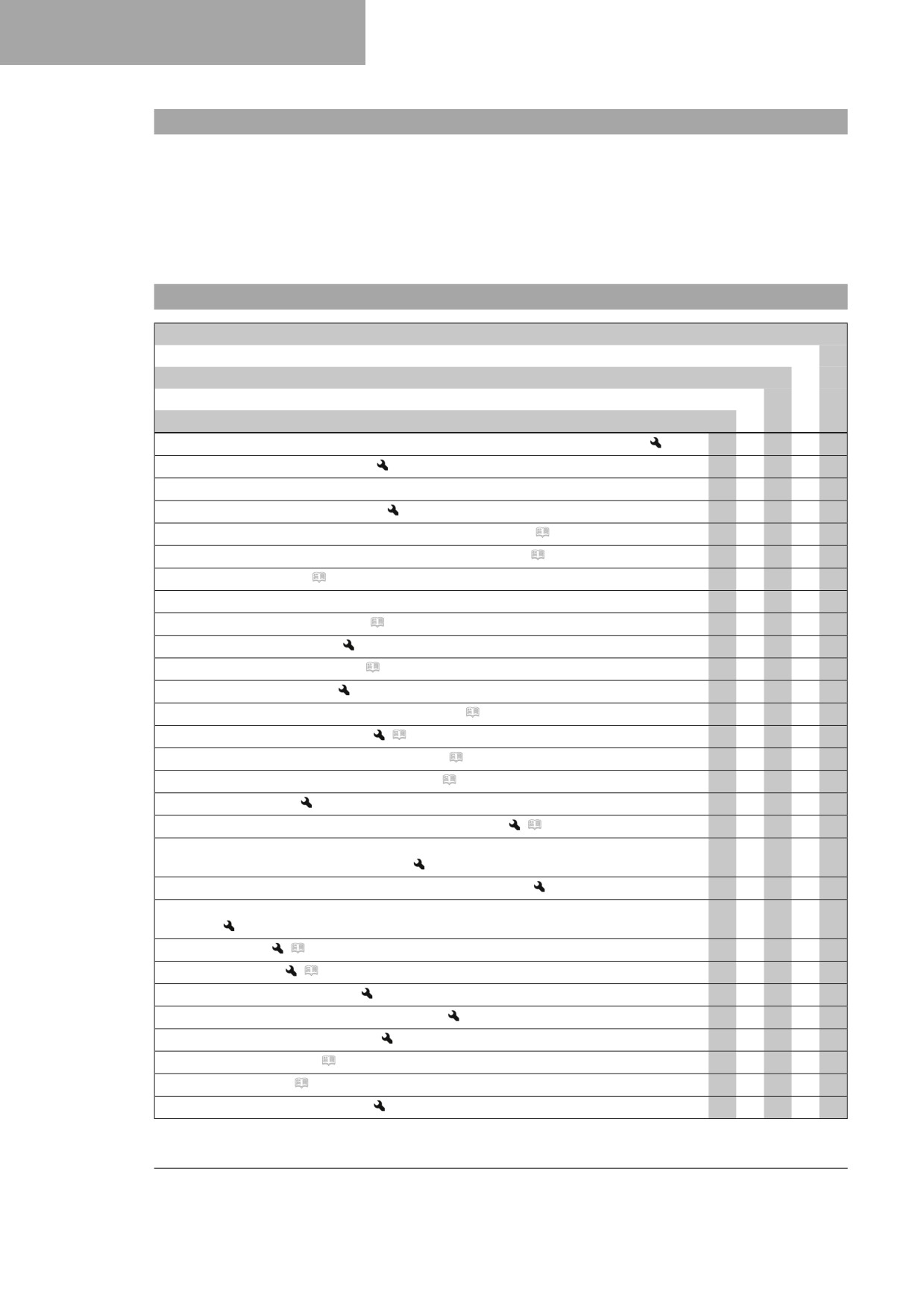
Service schedule
every 24 months
Every 90 operating hours
Every 45 operating hours
Every 15 operating hours
After 1 operating hour
Read out the fault memory using the Husqvarna Motorcycles diagnostics tool.
○
●
●
●
●
Program the gear position sensor.
●
●
●
Check that the electrical system is functioning properly.
○
●
●
●
Check and charge the 12-V battery.
○
●
●
●
●
Check that the brake linings of the front brake are secured. ( p. 85)
○
●
●
●
●
Check that the brake linings of the rear brake are secured. ( p. 91)
○
●
●
●
●
Check the brake discs. ( p. 82)
○
●
●
●
●
Check the brake lines for damage and tightness.
○
●
●
●
●
Check the front brake fluid level. ( p. 83)
○
●
●
Change the front brake fluid.
●
●
Check the rear brake fluid level. ( p. 89)
○
●
●
Change the rear brake fluid.
●
●
Check/correct the fluid level of hydraulic clutch. ( p. 79)
●
Change the hydraulic clutch fluid.
(
p. 80)
●
●
Check the free travel of the hand brake lever. ( p. 82)
○
●
●
●
●
Check the free travel of the foot brake lever. ( p. 88)
○
●
●
●
●
Check the idle speed.
○
●
●
●
●
Change the engine oil and oil filter, clean the oil screen.
(
p. 119)
○
●
●
●
●
Check all hoses (e.g. fuel, cooling, bleeder, drainage hoses, etc.) and sleeves for
○
●
●
●
●
cracking, tightness, and correct routing.
Check the cables for damage and for routing without kinks.
●
●
●
●
Check that the throttle cables are undamaged, routed without kinks, and set
●
●
●
●
correctly.
Check the frame.
(
p. 77)
●
●
●
Check the link fork.
(
p. 77)
●
●
●
Check the fork bearing for play.
●
●
Check the shock absorber heim joint for play.
●
●
Check the shock absorber linkage.
●
●
●
Check the tire condition. ( p. 99)
●
●
●
●
Check tire pressure. ( p. 99)
●
●
●
●
Check the wheel bearing for play.
●
●
●
34
SERVICE SCHEDULE
9
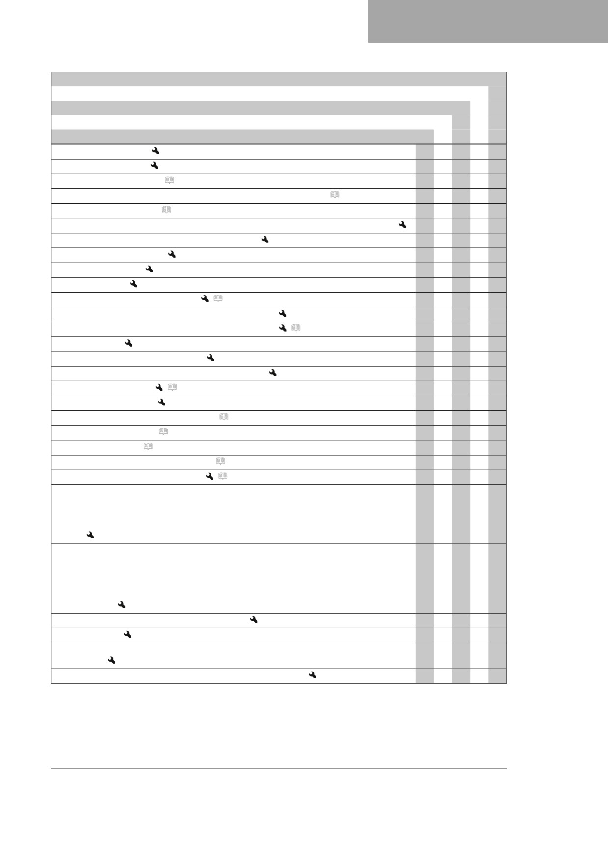
every 24 months
Every 90 operating hours
Every 45 operating hours
Every 15 operating hours
After 1 operating hour
Check the wheel hubs.
●
●
●
Check the rim run-out.
○
●
●
●
Check the spoke tension. ( p. 100)
○
●
●
●
Check the chain, rear sprocket, engine sprocket, and chain guide. ( p. 75)
○
●
●
●
Check the chain tension. ( p. 73)
○
●
●
●
●
Grease all moving parts (e.g., hand lever, chain,...) and check for smooth operation.
○
●
●
●
●
Change the spark plug and spark plug connector.
●
●
Check the valve clearance.
○
●
●
Change the fuel filter.
●
●
Check the clutch.
●
●
●
Clean the air filter and air filter box.
(
p. 65)
●
●
●
●
Check the funnel in the inlet sleeve in the air filter box.
●
●
●
●
Change the glass fiber yarn filling of the main silencer.
(
p. 68)
●
●
Service the fork.
●
●
Perform the shock absorber service.
●
●
Check all screws, nuts, and hose clips for a tight fit.
○
●
●
●
●
Change the fuel screen.
(
p. 117)
○
●
●
●
●
Check the fuel pressure.
○
●
●
●
Check the antifreeze and coolant level. ( p. 107)
●
●
Check the coolant level. ( p. 108)
○
●
Change the coolant. ( p. 110)
●
Check the steering head bearing play. ( p. 56)
○
●
Lubricate the steering head bearing.
(
p. 57)
●
●
●
Perform minor engine service including removing and installing the engine. (Change
●
●
the piston, check/measure the cylinder. Check the cylinder head. Check the camshafts
and valve train system components. Check the timing assembly. Change the radial
shaft seal rings and water pump gasket. Change the intake flange. Change inlet
sleeve.
Perform major engine service, engine is removed. (Change valves, valve springs, valve
●
spring seats, and valve spring retainer. Change the connecting rod, conrod bearing
and crank pin. Check the transmission and the shift mechanism. Check the oil pres-
sure control valve. Change the suction pump. Check the force pump and lubrication
system. Change the timing chain. Change all engine bearings and all gaskets. Change
the freewheel.)
Final check: check vehicle for operating safety.
○
●
●
●
●
Take a test ride.
○
●
●
●
●
Read out the fault memory after the test ride using the Husqvarna Motorcycles diag-
○
●
●
●
●
nostics tool.
Make a service entry in Husqvarna Motorcycles Dealer.net.
○
●
●
●
●
○ One-time interval
● Periodic interval
35
10
TUNING THE CHASSIS
10.1
Checking the basic chassis setting with rider's weight
Info
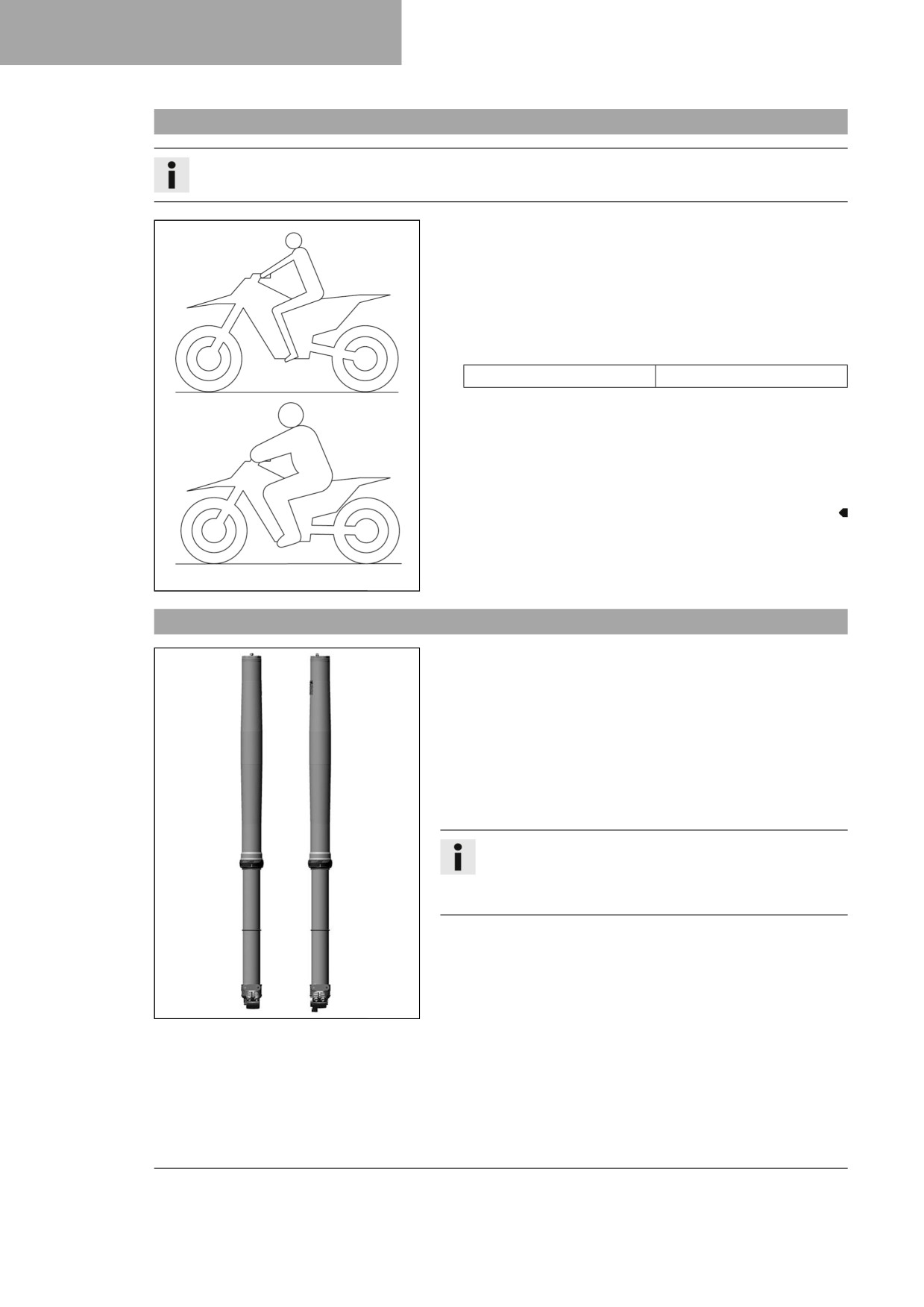
When adjusting the basic chassis setting, first adjust the shock absorber and then the fork.
- For optimal motorcycle riding characteristics and to avoid
damage to forks, shock absorbers, link fork and frame, the
basic settings of the suspension components must match the
rider's weight.
- In the delivered condition, Husqvarna motorcycles are
adjusted for an average rider's weight (with full protective
clothing).
Guideline
Standard rider weight
75 … 85 kg (165 … 187 lb.)
– If the rider's weight is above or below this range, the basic
setting of the suspension components must be adjusted
accordingly.
- Small weight differences can be compensated by adjusting
the spring pretension of the shock absorber, but in the case
of large weight differences, the springs must be replaced.
401030-01
10.2
Air suspension XACT
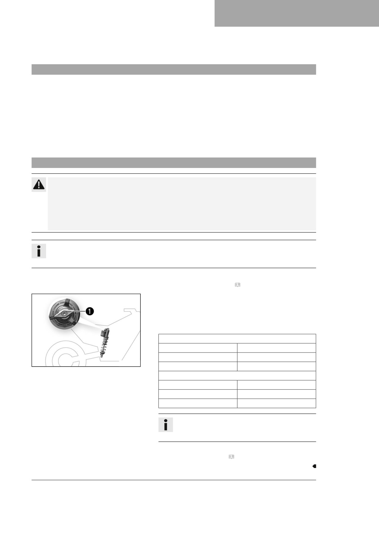
Air suspension WP XACT is used in the fork.
In this system, suspension is located in the left fork leg and
damping in the right fork leg.
As fork springs are no longer required, a significant weight
advantage is achieved when compared to conventional forks.
The response on slightly uneven surfaces is significantly
improved.
In normal driving mode, suspension is provided exclusively by an
air cushion. A steel spring is located in the left fork leg as an end
stop.
Info
If the fork is frequently overloaded, then the air pressure
in the fork must be increased to avoid damage to the fork
and frame.
The air pressure in the fork can be quickly adjusted to the rider's
weight, surface conditions and the rider's preference using a fork
airpump. The fork does not have to be dismantled. The time con-
suming mounting of harder or softer fork springs is not required.
If the air chamber loses air due to a damaged seal, the fork will
F03629-01
still not sag. In this case the air is retained in the fork. The sus-
pension travel is maintained as far as possible. The damping
becomes harder and the riding comfort reduces.
As with a conventional fork, the damping can be adjusted in
rebound and compression stages.
The rebound adjuster is located at the lower end of the right fork
leg.
36
TUNING THE CHASSIS
10
The compression adjuster is located at the upper end of the right
fork leg.
10.3
Compression damping of the shock absorber
The compression damping of the shock absorber is divided into two ranges: high-speed and low-speed.
High-speed and low-speed refer to the compression speed of the rear wheel suspension and not to the vehicle
speed.
The high-speed compression adjuster has an effect, for example, when landing after a jump: the rear wheel
suspension compresses quickly.
The low-speed compression adjuster has an effect, for example, when riding over long ground swells: the rear
wheel suspension compresses slowly.
These two ranges can be adjusted separately, although the transition between high-speed and low-speed is
gradual. Thus, modifications in the high-speed range affect the compression damping in the low-speed range
and vice versa.
10.4
Adjusting the low-speed compression damping of the shock absorber
Caution
Risk of injury Parts of the shock absorber will move around if the shock absorber is detached incor-
rectly.
The shock absorber is filled with highly compressed nitrogen.
- Please follow the description provided. (Your authorized Husqvarna Motorcycles workshop will be
glad to help.)
Info
The effect of the low-speed compression adjuster can be seen in slow to normal compression of the
shock absorber.
Preparatory work
- Remove the right side panel. ( p. 67)
Main work
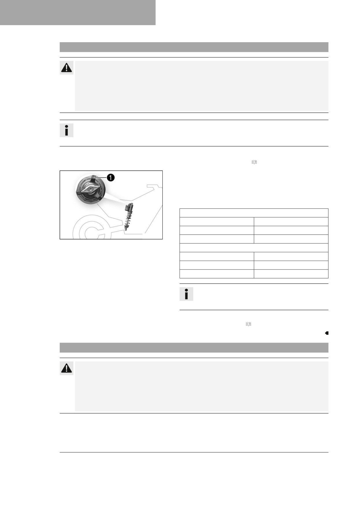
- Turn adjuster 1 clockwise all the way to the stop.
- Turn counterclockwise by the number of clicks correspond-
ing to the shock absorber type.
Guideline
Lowspeed compression damping (FC 250 EU)
Comfort
17 clicks
Standard
15 clicks
F03639-11
Sport
13 clicks
Lowspeed compression damping (FC 250 US)
Comfort
17 clicks
Standard
15 clicks
Sport
13 clicks
Info
Turn clockwise to increase damping; turn counter-
clockwise to reduce damping.
Finishing work
- Install the right side panel. ( p. 67)
37
10
TUNING THE CHASSIS
10.5
Adjusting the high-speed compression damping of the shock absorber
Caution
Risk of injury Parts of the shock absorber will move around if the shock absorber is detached incor-
rectly.
The shock absorber is filled with highly compressed nitrogen.
- Please follow the description provided. (Your authorized Husqvarna Motorcycles workshop will be
glad to help.)
Info
The effect of the high speed compression adjuster can be seen in the fast compression of the shock
absorber.
Preparatory work
- Remove the right side panel. ( p. 67)
Main work
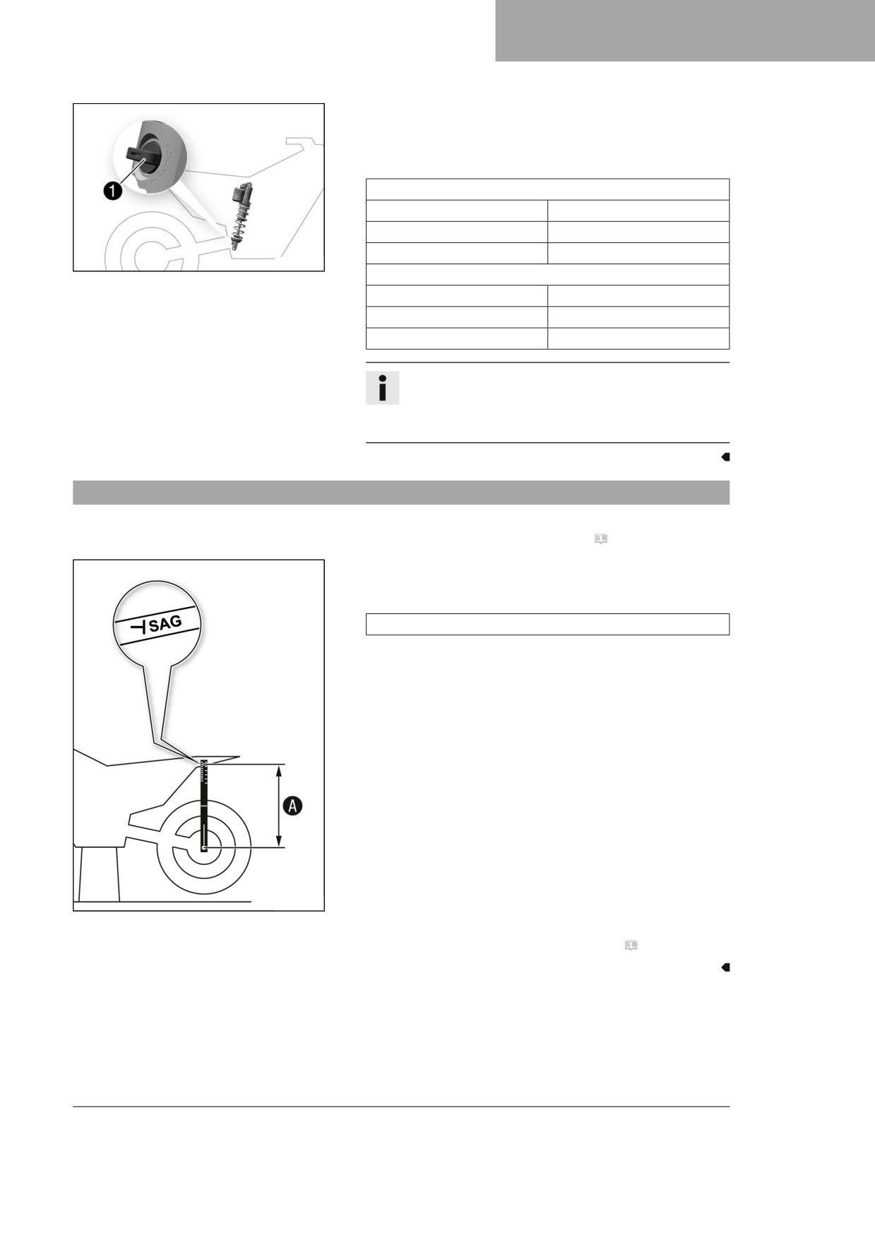
- Turn adjuster 1 clockwise all the way to the stop.
- Turn counterclockwise by the number of turns corresponding
to the shock absorber type.
Guideline
Highspeed compression damping (FC 250 EU)
Comfort
2 turns
Standard
1.5 turns
F03639-10
Sport
1 turn
Highspeed compression damping (FC 250 US)
Comfort
2 turns
Standard
1.5 turns
Sport
1 turn
Info
Turn clockwise to increase damping; turn counter-
clockwise to reduce damping.
Finishing work
- Install the right side panel. ( p. 67)
10.6
Adjusting the rebound damping of the shock absorber
Caution
Risk of injury Parts of the shock absorber will move around if the shock absorber is detached incor-
rectly.
The shock absorber is filled with highly compressed nitrogen.
- Please follow the description provided. (Your authorized Husqvarna Motorcycles workshop will be
glad to help.)
38
TUNING THE CHASSIS
10
– Turn adjuster 1 clockwise up to the last perceptible click.
- Turn counterclockwise by the number of clicks correspond-
ing to the shock absorber type.
Guideline
Rebound damping (FC 250 EU)
Comfort
17 clicks
Standard
15 clicks
Sport
13 clicks
F03640-10
Rebound damping (FC 250 US)
Comfort
17 clicks
Standard
15 clicks
Sport
13 clicks
Info
Turn clockwise to increase the damping; turn
counterclockwise to reduce damping when the shock
absorber rebounds.
10.7
Measuring the dimension of the rear wheel unloaded
Preparatory work
- Raise the motorcycle with a lift stand. ( p. 49)
Main work
- Position the sag gage in the rear axle and measure the
distance to marking SAG on the rear fender.
Sag gage (00029090200)
- Note the value as dimension A.
402415-10
Finishing work
- Remove the motorcycle from the lift stand. ( p. 49)
39
10
TUNING THE CHASSIS
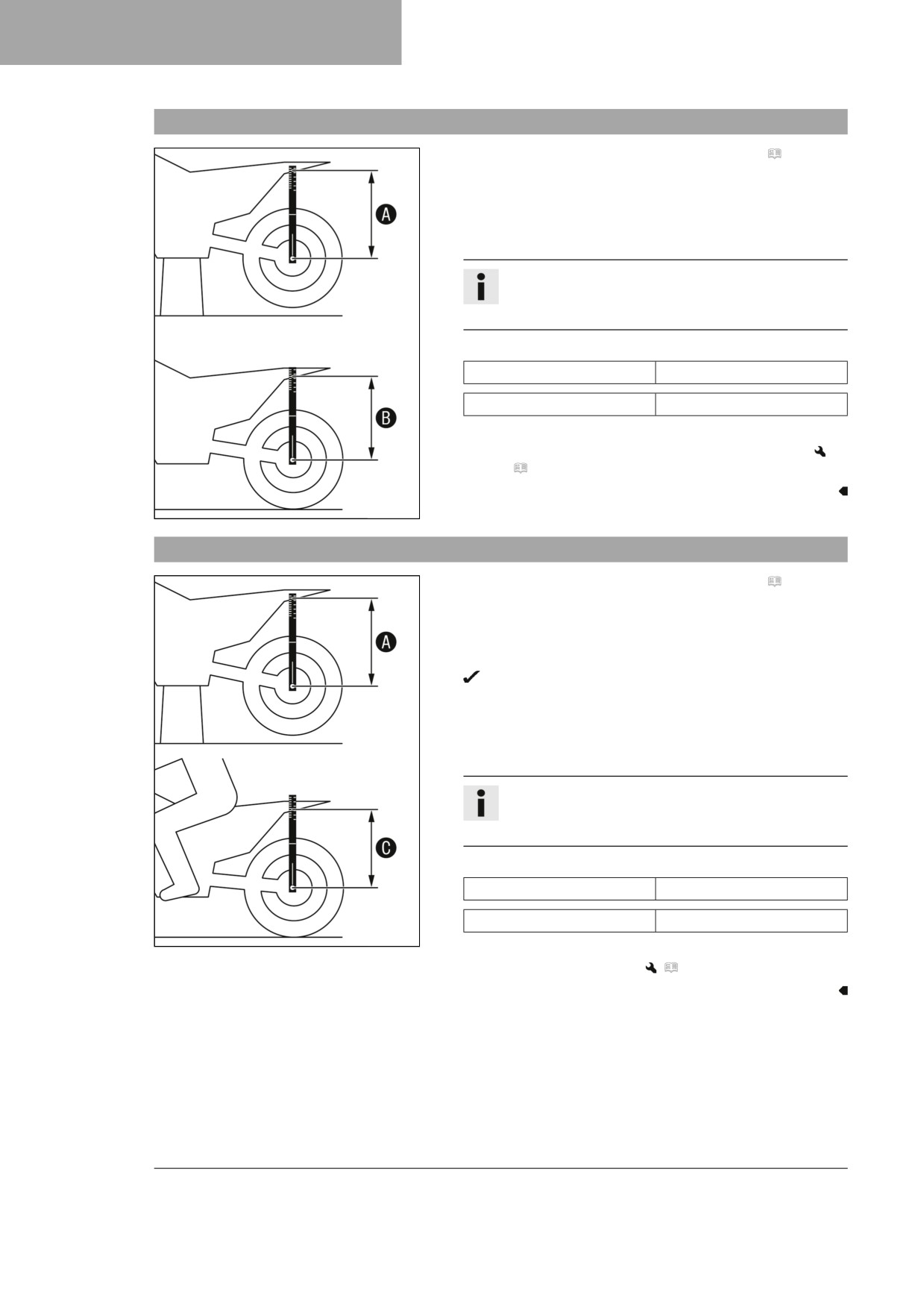
10.8
Checking the static sag of the shock absorber
- Measure dimension A of rear wheel unloaded. ( p. 39)
- Hold the motorcycle upright with aid of an assistant.
- Measure the distance again between the rear axle and mark-
ing SAG on the rear fender using the sag gage.
- Note the value as dimension B.
Info
The static sag is the difference between measure-
ments A and B.
- Check the static sag.
Static sag (FC 250 EU)
35 mm (1.38 in)
Static sag (FC 250 US)
35 mm (1.38 in)
» If the static sag is less or more than the specified value:
- Adjust the spring preload of the shock absorber.
(
p. 41)
402416-10
10.9
Checking the riding sag of the shock absorber
- Measure dimension A of rear wheel unloaded. ( p. 39)
- With another person holding the motorcycle, the rider, wear-
ing full protective clothing, sits on the seat in a normal sitting
position (feet on footrests) and bounces up and down a few
times.
The rear wheel suspension levels out.
- Another person again measures the distance between the
rear axle and marking SAG on the rear fender using the sag
gage.
- Note the value as dimension C.
Info
The riding sag is the difference between measure-
ments A and C.
- Check riding sag.
Riding sag (FC 250 EU)
105 mm (4.13 in)
Riding sag (FC 250 US)
105 mm (4.13 in)
402417-10
» If the riding sag differs from the specified measurement:
- Adjust the riding sag.
(
p. 42)
40
//////////////////////////////////////////