VM Motori D700/750 E2-E3. Manuale del motore in 5 lingue (2009) - 3
D700/750 E2-E3
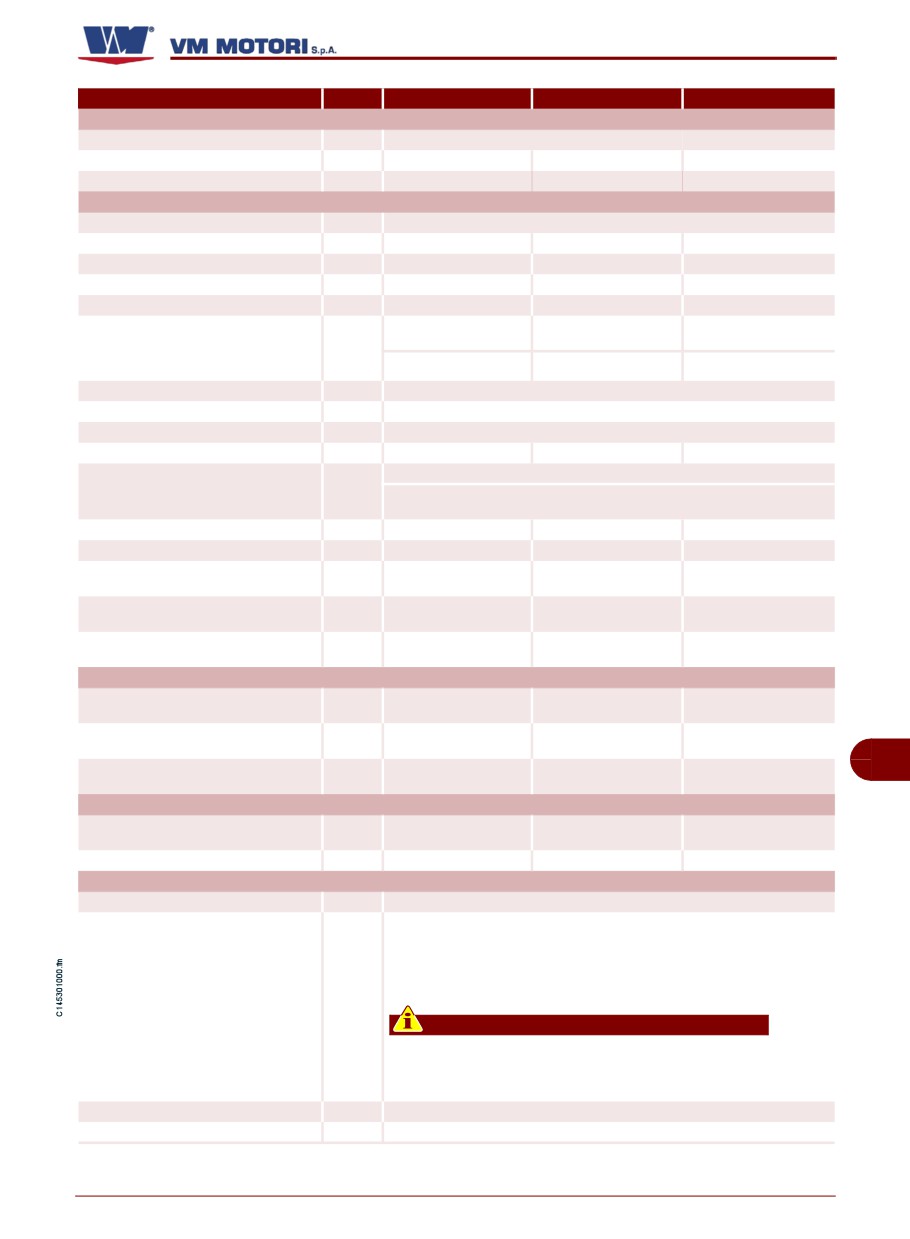
Model
D754 TE3
D754 SE3
D754 IE3
DIMENSIONS
A
mm
702
702
702
B
mm
557
557
557
C
mm
736
736
736
GENERAL DATA
Cycle
Four stroke diesel
Total displacement
liters
2,970
2,970
2,970
Number of cylinders
n.
4
4
4
Bore and stroke
mm
94x107
94x107
94x107
Compression ratio
18 ± 0,5:1
18 ± 0,5:1
18 ± 0,5:1
Supercharged
Turbocharged and
Natural
inter-cooled circuit
Intake
circuit
(Dry) air filter
(Dry) air filter
(Dry) air filter
Cooling
Water circuit
Cooler
Water/oil
Crankshaft rotation
Anticlockwise (observing the engine from the handwheel side)
Combustion sequence
1-3-4-2
1-3-4-2
1-3-4-2
Pushrods and rocker arms with hydraulic tappets and camshaft
Timing
Gear cascade control and camshaft fitted on the crankbase
Minimum idling speed (standard engine)
rpm
900 +/-50
800-850
800-850
Dry shipping weight of engine
Kg
250
250
250
Maximum permanent lengthwise inclina-
Degrees
30°
30°
30°
tion (with handwheel up)
Maximum permanent lengthwise inclina-
Degrees
35°
35°
35°
tion (with handwheel down)
Maximum permanent crosswise inclina-
Degrees
30°
30°
30°
tion
POWER AND TORQUE
Maximum operating speed
rpm
2600
2600
2600
kW (CV)
Maximum power
59,8 (81,3)
51,5 (70)
70 (95,2)
rpm
Nm
GB
Maximum torque
(kgm)
274 (27,9) a 1800
220 (22,4) a 1400
400 (40,7) a 1000
CONSUMPTION AT MAXIMUM POWER
Specific fuel consumption
g/kWh
Specific oil consumption
g/CVh
0,5 - 1
0,5 - 1
0,5 - 1
FUEL SUPPLY CIRCUIT
Type of injection
Iniezione diretta
The engine has been designed to be powered by standard fuels available on the
European market (according to specifications DIN EN 590). If it is to be powered
by BIODIESEL fuels (according to specifications UNI EN 14214), it can be
mixed, up to 5%, with fuel available on the European market (according to regu-
lation DIN EN 590).
Type of fuel
Important
Do not use fuels with specifications other than those indicated.
Fuel supply
Diaphragm pump
Injector supply
Mechanical rotary injection pump
English
- 19 -
Technical information
D700/750 E2-E3
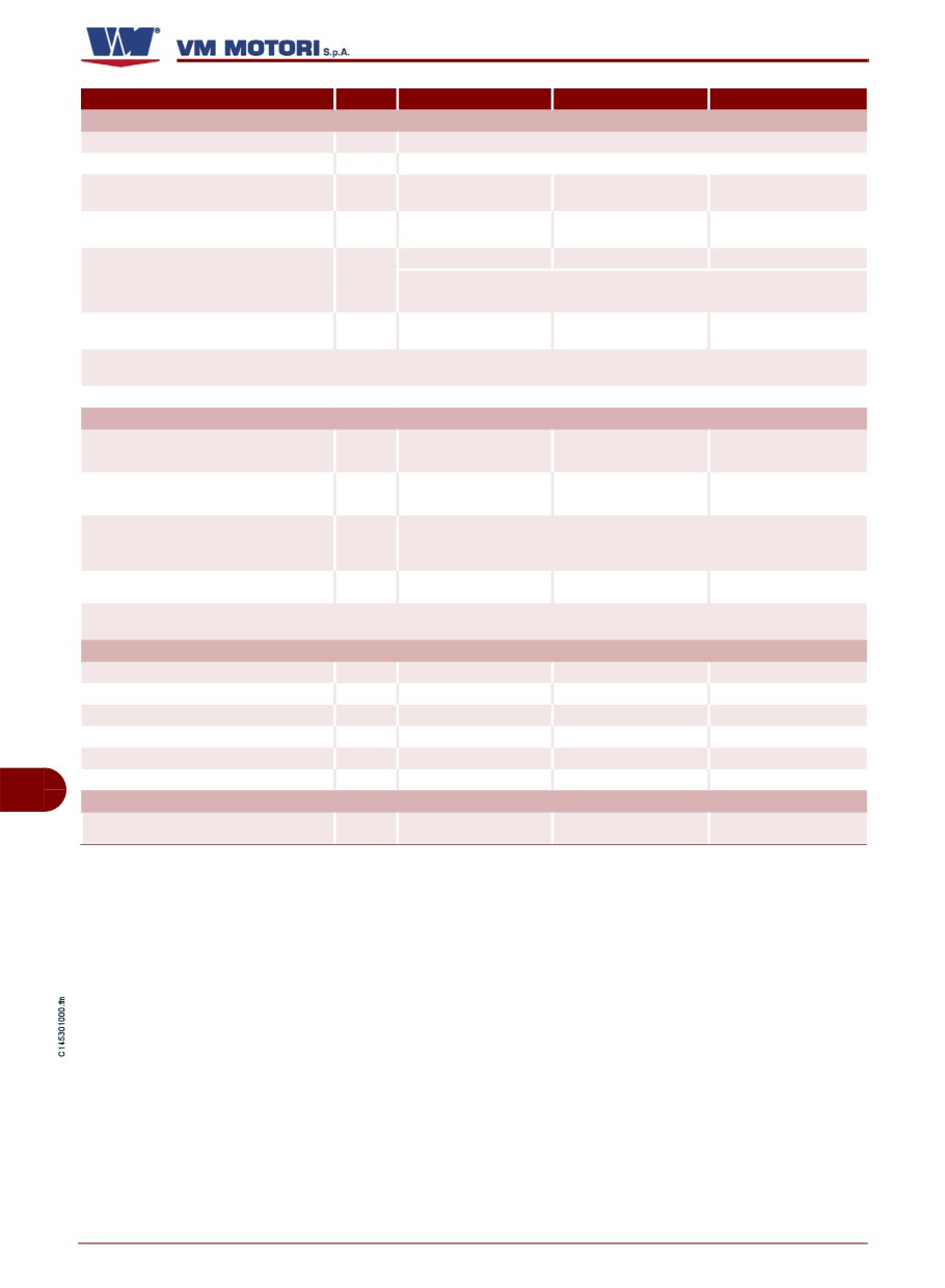
Model
D754 TE3
D754 SE3
D754 IE3
LUBRICATION CIRCUIT
Type of lubrication
Forced lubrication
Circuit fuel supply
Rotor pump
Oil change including filter
liters (kg)
(standard sump)
Oil quantity at minimum level
liters (kg)
(standard sump)
liters (kg)
7÷10
7÷10
7÷10
Oil quantity at maximum level
The oil quantity at maximum level ( 7÷10 litre) depends on the capacity of the oil
sump with which the engine is equipped.
Oil pressure at minimum speed
bar
1,2 - 1,6
1,2 - 1,6
1,2 - 1,6
(with started engine)
Alarm for oil pressure too low
bar
0,4
0,4
0,4
Oil cooling
Oil/water cooler
COOLING CIRCUIT
Total capacity of the cooling circuit
litri
5
5
5
(excluding radiator and relevant pipes)
setting pressure of the expansion tank
bar
1
1
1
plug
Demineralised cold water 50% + Antioxidant and anti-freeze fluid 50% (Inhibited
Coolant
glycol ethylene in compliance with ASTM D 3306)
Coolant maximum temperature alarm
°C
107
107
107
Opening value (start/finish) of thermostatic
°C
80 (+/-2) / 95
80 (+/-2) / 95
80 (+/-2) / 95
valve
ELECTRIC SYSTEM
Nominal voltage
V
12
12
12
Alternating current generator (nominal volt-
V
14
14
14
Alternating current generator (nominal cur-
A
55
70
70
Starter motor output
kW
2,3
2,3
2,3
Recommended battery capacity
Ah
92
110
110
Battery breakaway current
A
480
880
880
GB
SUCTION CIRCUIT
Maximum depression allowed with new air
mbar
15
15
15
filter
English
- 20 -
Technical information
D700/750 E2-E3
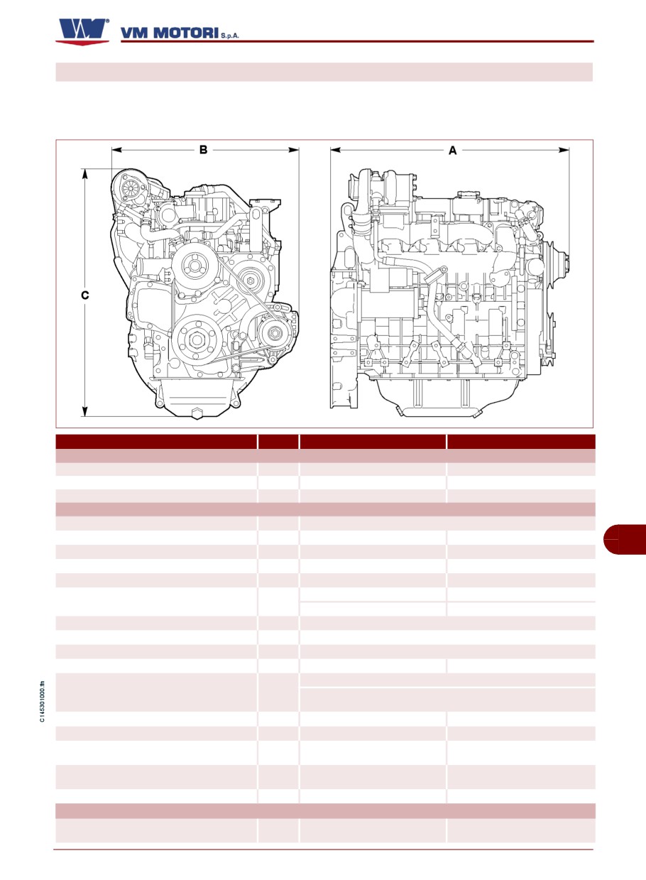
TECHNICAL DATA (D754 TPE2/D756 IPE2)
These technical data and specifications re-
fer exclusively to standard VM MOTORI
S.P.A. engines.
IDM-45300900600.tif
Model
D754 TPE2
D756 IPE2
DIMENSIONS
A
mm
1176
1542
B
mm
647
695
C
mm
903
965
GENERAL DATA
Cycle
Four stroke diesel
Total displacement
liters
2,970
4,455
GB
Number of cylinders
n.
4
6
Bore and stroke
mm
94x107
94x107
Compression ratio
17,8 ± 0,5:1
17,8 ± 0,5:1
supercharged circuit
supercharged circuit
Intake
(Dry) air filter
(Dry) air filter
Cooling
Water circuit
Cooler
water/oil
Crankshaft rotation
Anticlockwise (observing the engine from the handwheel side)
Combustion sequence
1-3-4-2
1-5-3-6-2-4
Pushrods and rocker arms With hydraulic tappets and camshaft
Timing
Gear cascade control and camshaft fitted on the crankbase
Minimum idling speed (standard engine)
rpm
1200±50
1200±50
Dry shipping weight of engine
Kg
260
335
Maximum permanent lengthwise inclination (with
Degrees
30°
30°
handwheel up)
Maximum permanent lengthwise inclination
Degrees
35°
35°
(with handwheel down)
Maximum permanent crosswise inclination
Degrees
30°
30°
POWER AND TORQUE
Maximum operating speed
rpm
2300
2300
English
- 21 -
Technical information
D700/750 E2-E3
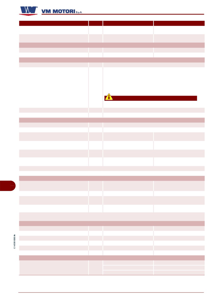
Model
D754 TPE2
D756 IPE2
kW (CV)
Maximum power
62 (84,3)
102 (138,7)
rpm
Nm
Maximum torque
(kgm)
366 (37,3) a 1200
613 (62,5) a 1200
CONSUMPTION AT MAXIMUM POWER
Specific fuel consumption
g/kWh
250
230
Specific oil consumption
g/CVh
FUEL SUPPLY CIRCUIT
Type of injection
Direct injection
The engine has been designed to be powered by standard fuels available
on the European market (according to specifications DIN EN 590). If it is to
be powered by BIODIESEL fuels (according to specifications UNI EN
14214), it can be mixed, up to 5%, with fuel available on the European
Type of fuel
market (according to regulation DIN EN 590).
Important
Do not use fuels with specifications other than those indicated.
Fuel supply
Diaphragm pump
Injector supply
Mechanical rotary injection pump
LUBRICATION CIRCUIT
Type of lubrication
Forced lubrication
Circuit fuel supply
Rotor pump
Oil change including filter (standard sump)
liters (kg)
8,8
12,3
Oil quantity at minimum level (standard sump)
liters (kg)
The oil quantity at maximum level ( litre) depends on the capacity of the oil
Oil quantity at maximum level
liters (kg)
sump with which the engine is equipped.
Oil pressure at minimum speed (with started
bar
2
1,5
engine)
Alarm for oil pressure too low
bar
0,3 - 0,5
0,3 - 0,5
Oil cooling
Oil/water cooler
COOLING CIRCUIT
Total capacity of cooling circuit (excluding radiator
GB
liters
5
7,5
and relevant pipes)
Setting pressure of the expansion tank plug
bar
1,1
1,1
Demineralised cold water 50% + Antioxidant and anti-freeze fluid 50%
Coolant
(Inhibited glycol ethylene in compliance with ASTM D 3306)
Coolant maximum temperature alarm
°C
109
109
Opening value (start/finish) of thermostatic valve
°C
80-90
80-90
ELECTRIC SYSTEM
Nominal voltage
V
12 o 24
12 o 24
Alternating current generator (nominal voltage)
V
14 o 28
14 o 28
Alternating current generator (nominal current)
A
55
55
Starter motor output
kW
2,3
2,3
Recommended battery capacity
Ah
92
100
Battery breakaway current
A
480
550
SUCTION CIRCUIT
20 a 1500 rpm
20 a 1500 rpm
Maximum depression allowed with new air filter
mbar
25 a 1800 rpm
25 a 1800 rpm
40 a 2300 rpm
35 a 2300 rpm
English
- 22 -
Technical information
D700/750 E2-E3
SAFETY INFORMATION
SAFETY RULES
- During the design and construction phas-
- All the installation phases should have
es, the Manufacturer paid special attention
been taken into account since the develop-
to the aspects which are liable to cause any
ment of the initial project. The designer has
risk for the safety and health of people inter-
to observe with the engine fixing points and
acting with the engine. Besides complying
the general indications provided by the
with the relevant legislation in force, he fol-
manufacturer.
lowed all the "rules for a good construction
- Carry out the handling of the engine in
technique". The purpose of this information
compliance with the information stated di-
is making users aware of the need to pay
rectly on the engine, on the packaging and
the utmost attention to prevent any risk.
in the operating instructions supplied by the
Caution is however imperative. Safety also
manufacturer.
depends on all the operators who interact
with the engine.
- When lifting or transporting unpacked en-
gines use means of appropriate load capac-
- Read carefully the instructions contained
ity which must be properly anchored.
in the manual supplied and those applied on
the engine, in particular follow those con-
- When lifting and transporting packaged
cerning safety. Spend some of your time
engines, means of appropriate load capaci-
reading the instructions to avoid unpleasant
ty as stated on the packaging itself.
accidents.
- Before carrying out other transfers, cre-
- Pay attention to the meaning of the sym-
ate the conditions required to guarantee sta-
bols in the applied plates; their shape and
bility and to prevent any engine part from
colour have a specific meaning related to
being damaged.
safety. Keep them visible and follow the
GB
- Before starting the installation, the install-
stated information.
er has to implement a "safety plan" and to
- Use the engine only for the tasks author-
follow the designer’s indications. Do not
ised by the manufacturer and do not tamper
make changes to the engine components
with any device to achieve a different per-
for any reason.
formance from the intended one.
- It is necessary to make sure that the in-
- The staff carrying out any type of inter-
stallation area is fitted with all intake, fuel
vention throughout the life of the engine
supply and exhaust connections.
should have precise technical skills, specific
abilities and experiences acquired and ac-
knowledged in this sector. The lack of these
requirements may cause damages to peo-
ple’s safety and health.
English
- 23 -
Safety information
D700/750 E2-E3
In the state of California, diesel engine
- Start again the engine only when the nor-
exhaust gases are recognized as one of
mal operating conditions have been restored.
the main causes of cancerous tumors,
- Unless otherwise stated, all interventions
damage to reproductive organs and de-
should be carried out when the engine has
formities in unborn children.
been stopped, cooled down and the ignition
Whenever an engine enters the state of
key has been removed. Those authorized to
California, or states or countries which
carry out these interventions should follow
adopt the same legislation, adequate in-
all the precautions needed to guarantee the
formation must be provided to confirm
safety of the people involved, in compliance
the risks associated with the engine’s
with the requirements laid down in the appli-
components and the exhaust gases
cable legislation regarding safety at the
which it produces.
workplace.
- The manufacturer cannot be held re-
- Keep the equipment as much efficient as
sponsible for any damage resulting from the
possible and carry out the scheduled main-
misuse of the engine, from the failure to fol-
tenance operations established by the man-
low the indications contained in this manual
ufacturer. A good maintenance will ensure
and from any tampering with or change
the highest performance, a longer working
made without the manufacturer’s authoriza-
lifetime and a constant compliance with
tion.
safety requirements.
- If appropriate, before using the engine for
- Replace any worn part with original spare
the first time, after gathering all the neces-
parts. Use the oils and greases recom-
sary information, simulate a few trial ma-
mended by the manufacturer. All this will en-
noeuvres to identify the controls and their
sure the engine good operation and the
main functions, especially those related with
prescribed safety level.
starting and stop operations.
- Do not throw away any polluting material
GB
- Do not operate the engine in a closed
in the environment. Carry out their disposal
and insufficiently ventilated environment;
in compliance with the relevant legislation in
the exhaust fumes are harmful and can
force.
have serious consequences on people’s
health.
- During all maintenance operations al-
ways use the individual protection clothing
- Do not keep using the engine if anoma-
and/or devices indicated in the operating in-
lies are detected and in particular if suspect
structions supplied by the manufacturer and
vibrations occur.
those provided by the applicable legislation
- In case of anomaly, stop immediately the
concerning safety at the workplace.
engine or reduce the speed as much as pos-
- All maintenance operations should be
sible and reach the closest assistance cen-
carried out by using suitable and efficient
tre.
equipment and tools.
English
- 24 -
Safety information
D700/750 E2-E3
SAFETY RULES FOR THE ENVIRONMENTAL IMPACT
Each organization is responsible for imple-
- All packaging components should be dis-
menting procedures aimed at identifying,
posed of in accordance with the legislation
evaluating and controlling the environmen-
in force in the country where disposal takes
tal impact of its own activities
(products,
place.
services, etc.).
The procedures to be followed to identify
- When installing the engine, ensure a suit-
any significant environmental impact should
able air renewal in the environment to pro-
take into account the following factors:
tect the operators from a high concentration
of harmful substances.
- Emissions in the atmosphere
- During operation and maintenance, do
- Discharged liquids
not throw away polluting products
(oils,
greases, etc) in the environment and carry
- Waste disposal
out the differentiated waste disposal accord-
- Soil contamination
ing to the composition of the different mate-
rials and in compliance with the legislation in
- Use of raw materials and natural resourc-
force. Electric and electronic components
es
should be carried out as special waste.
- Local problems related to the environ-
- Keep the exhaust pipelines efficient to
mental impact. In order to reduce the envi-
limit the noise level of the engine and to re-
ronmental impact, the manufacturer
duce atmospheric pollution.
provides below a few indications to be taken
into account by all those who will interact
- While decommissioning the engine, di-
with the engine throughout its expected life.
vide all the components depending on their
chemical composition and dispose of them
accordingly.
GB
RESIDUAL RISKS
During the design and construction of the
When planning the installation of the engine
engine, the constructor has paid particular
onto the vehicle, the installation technician
attention to aspects which may present a
must conduct an analysis to evaluate the
potential risk to the health and safety of peo-
potential risks from moving components
ple who come into contact with the engine.
(danger of becoming trapped in the trans-
Despite this, some potential and hidden
mission belt) and other hazardous zones
risks still exist.
(danger of scalding).
Once the engine is installed, before starting
Danger of injuring your arms
the engine for the first time, evaluate wheth-
Do not put your hands inside any moving
er the potentially hazardous zones have
part.
been fitted with adequate safety devices.
Danger of being burnt
Pay attention to hot surfaces
English
- 25 -
Safety information
D700/750 E2-E3
HANDLING AND INSTALLATION INFORMATION
RECOMMENDATIONS FOR HANDLING AND INSTALLATION
Carry out handling and installation following
carry out these operations should prepare, if
the information provided by the manufactur-
necessary, a "safety plan" to protect and the
er and stated directly on the packaging and
safety of people directly involved.
operating instructions. Those authorized to
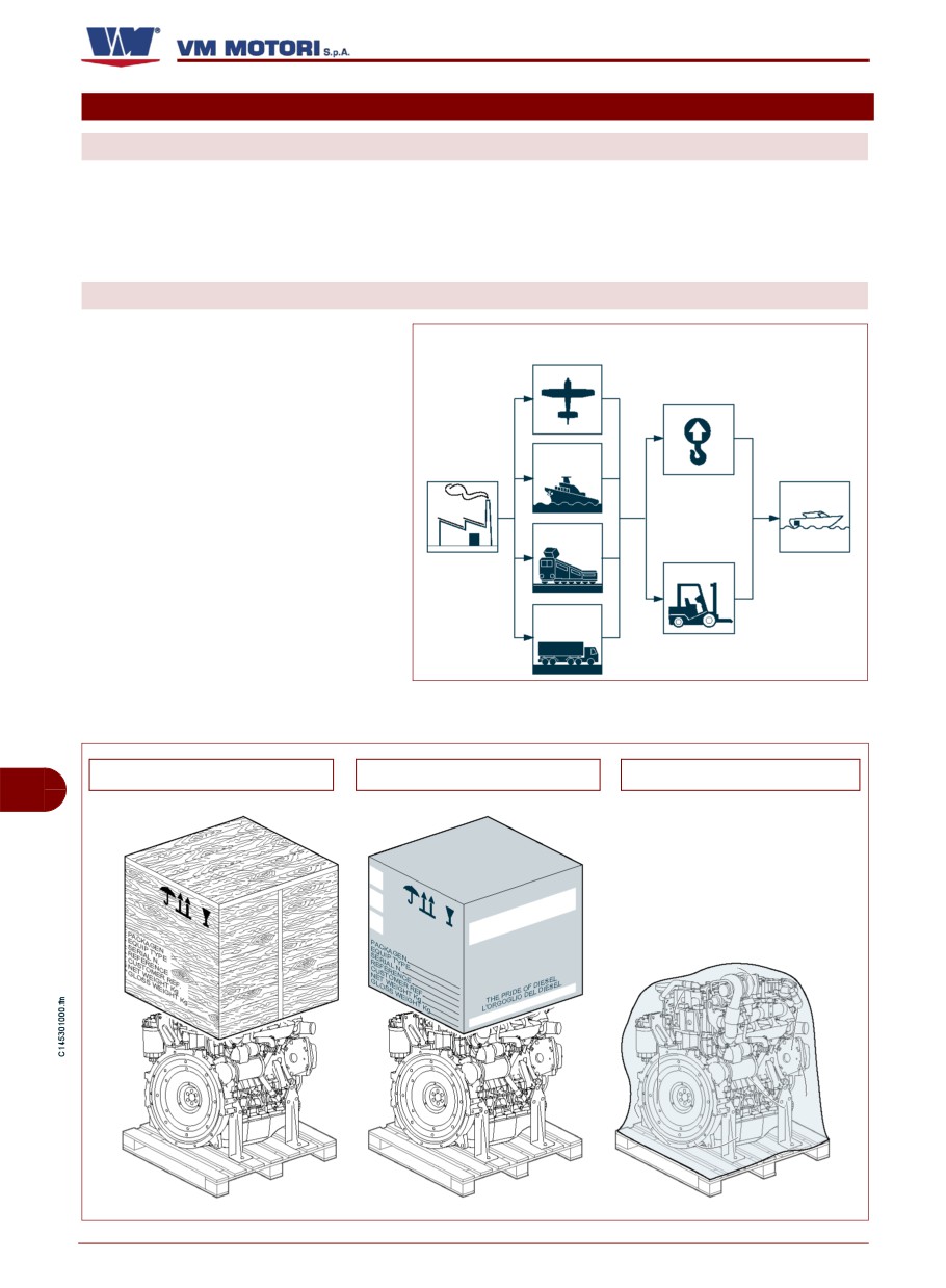
PACKAGING AND TRANSPORT
The packaging is also made accord-
Means of
ing to the type of transport chosen to
transport
keep sizes as small as possible.
Lifting
equipment
- By road
- By railway
- By sea
- By air
The engine can be transported with
different types of packaging accord-
ing to the destination, the transport
IDM-45300300700.tif
system and preset technical-com-
mercial specifications.
Packaging with wooden case
Packaging with cardboard box
Packaging with cellophane
GB
IDM-45300900700.tif
English
- 26 -
Handling and installation information
D700/750 E2-E3
In order to guarantee the perfect con-
servation of all engine components,
an "overseas" packaging should be
used in case of maritime transport.
The packaging contains all the infor-
mation needed to carry out the load-
ing and unloading operations.
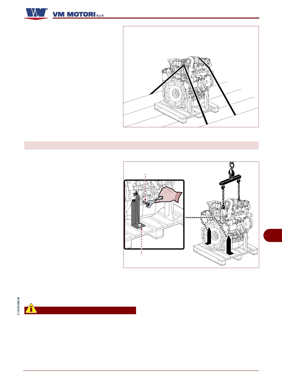
During transport, make sure the load
is properly secured to the means of
transport to avoid unexpected dis-
placements.
When transporting the uncovered en-
gine by road, use the lifting points pro-
vided to secure it steadily and prevent
IDM-45300900800.tif
components from being damaged.
UNPACKING
Follow the procedure below.
1- Remove the cover of the packag-
ing. The packaging includes a bag
Screw (A)
with all the relevant technical docu-
mentation and standard components.
2-While unpacking, make sure the
components are intact and their quan-
tity is correct.
3-Place the lifting device as shown
in the figure.
GB
4-Loosen the screws (A) and disas-
semble the side supports (B).
Stay (B)
5-Move the engine to the installa-
IDM-45300900900.tif
tion area.
If necessary, keep the material in
case you need to pack the engine in
the future.
Important
In case of any damage or missing part,
contact the manufacturer’s Assistance
Service to establish the procedure to be
adopted. The packaging material should
be suitably eliminated in compliance
with the applicable legislation.
English
- 27 -
Handling and installation information
D700/750 E2-E3
HANDLING AND LIFTING
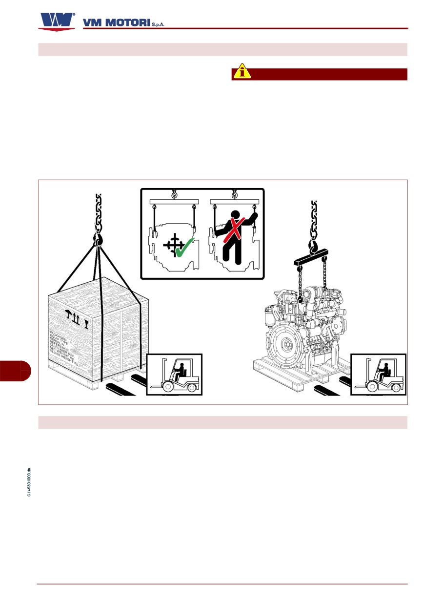
Secure the engine with a lifting device (lift-
ing beam) of appropriate capacity.
Important
Hook the lifting device to the fixing points as
The brackets of the fixing points have
shown in the figure.
been designed to lift the engine only
Before carrying out the lifting, identify the
without any additional weight. Do not lift
barycentre position of the load.
the engine using a different procedure
from the prescribed one; otherwise, the
warranty for damages will be invalidated.
GB
IDM-45300901000.tif
ENGINE STORAGE
If the engine is left idle for prolonged peri-
The manufacturer supplies the engine with
ods, check the possible conditions of con-
a protection treatment which is valid for 6
servation in relation to the storage area and
months from the delivery date.
the type of packaging.
After the first 6 months, if the engine is not
Avoid any environment exposed to damp-
used, it is necessary to carry out a specific
ness or to the inclemency of weather.
maintenance to extend the storage period
for a further 6-month period.
The information related to the extension of
the storage period are included in the gener-
al warranty conditions.
English
- 28 -
Handling and installation information
D700/750 E2-E3
INSTALLATION DESIGN
In order to ensure the highest performance
During the design and installation phases, it
while protecting people, the product itself
is advisable to consult the service manual
and the environment, a full project has to be
supplied by VM MOTORI S.P.A..
developed before carrying out the installa-
Further information are available in the web-
tion.
site: www.vmmotori.it, in the "Contacts -
The design phase should take into account
Request Info" section.
the technical data of the engine (see"Tech-
nical data") and all the risks which may oc-
cur during its expected lifetime, from
installation to disposal.
GB
English
- 29 -
Handling and installation information
D700/750 E2-E3
ADJUSTMENT INFORMATION
RECOMMENDATIONS FOR ADJUSTMENTS
Before carrying out any adjustment, activate
source of unexpected danger and risk for
all safety devices and evaluate the need to
people's safety and health
inform the personnel working on the engine
or nearby. In particular, place proper signs
in the nearby areas and keep away all devic-
es which, once activated, may represent a
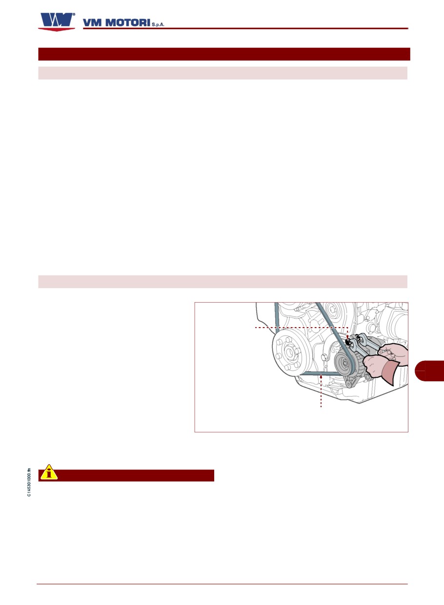
HOW TO ADJUST THE TENSION OF THE DRIVING BELT
Follow the procedure below.
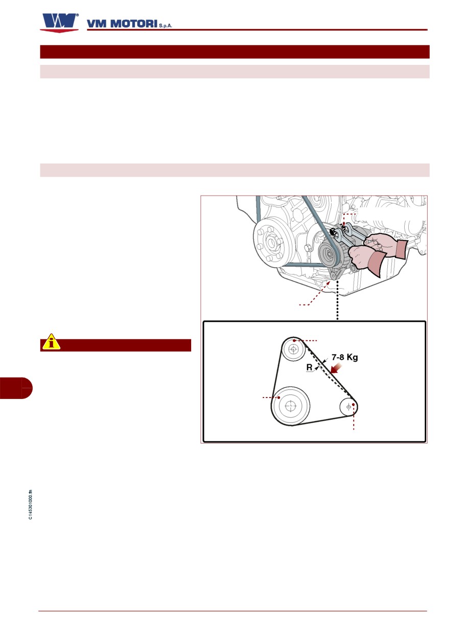
1- Turn off the engine and remove
the ignition key.
Nut (A)
2-Let the engine cool down ade-
quately to avoid being burnt.
3-Loosen nut (A).
4-Adjust alternating current gener-
ator (B) manually and at the same
Alternating current
time tighten nut (A) to regulate belt
tension.
Water pump
Important
To check belt tension, use the
method shown in figure. The re-
sulting shifting (R) must be 10
GB
mm.
Drive shaft
Alternating current generator
IDM-45300901300.tif
English
- 30 -
Adjustment information
D700/750 E2-E3
OPERATING INFORMATION
RECOMMENDATIONS FOR USE AND OPERATION
The engine has been designed and manu-
ferent performance from the intended one
factured to satisfy all the operating condi-
can entail risks for people's safety and
tions indicated by the manufacturer.
health as well as economic damages.
Tampering with any device to achieve a dif-
CONTROL BOARD DESCRIPTION
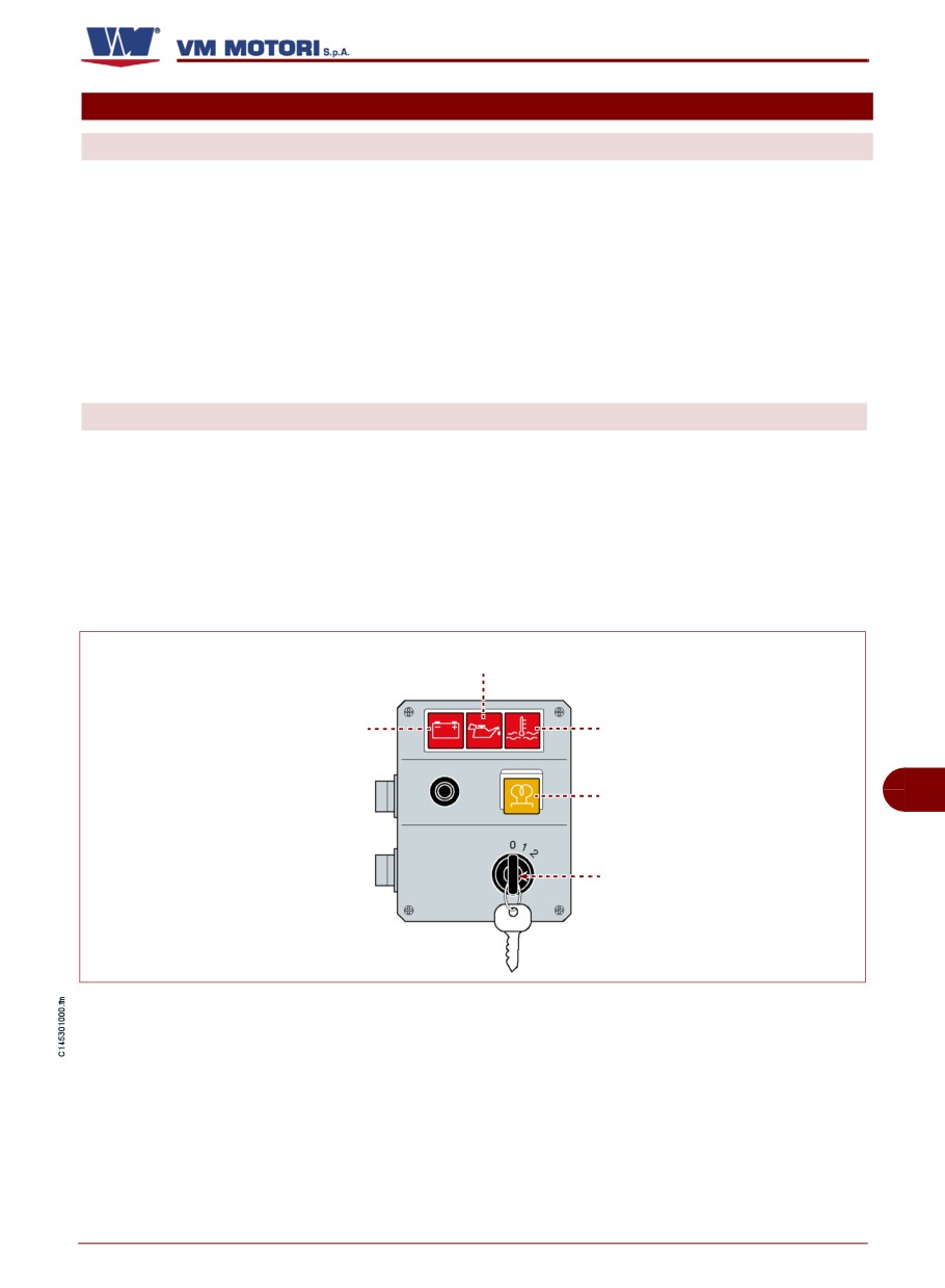
A) Indicator (red lamp): indicates that the
D) Warning light (orange): It signals the
alternator is not charging the battery.
pre-heating of the glowplugs
When the warning light goes off, it is possi-
B) Warning light (red): It signals that the
ble to start the engine.
engine oil pressure is low
E) Ignition key switch: It is used to start
C) Warning light (red): indicates that the
the engine
coolant temperature is too high
Engine oil indicator (B)
Battery indicator (A)
Coolant indicator (C)
Glow plugs indicator (D)
GB
Ignition key (E)
IDM-45300901900.tif
English
- 31 -
Operating information
D700/750 E2-E3
RECOMMENDATIONS FOR USE
During the running-in period (first 50 hours
- During running-in (first 50 working hours)
of operation), the engine must be used with
and throughout the engine lifetime, carry out
an absorbed load of between 50% and 70%
the maintenance in compliance with the in-
of maximum power.
tervals established by the manufacturer
(See "Engine maintenance").
- Avoid using the engine at the highest
speed for prolonged periods during running-
Important
in.
If the engine is not used regularly, start it
- During the running-in period, do not run
after each month of inactivity and run it at
the engine with an absorbed load of less than
minimum speed until the operating tem-
50% or at low idle speed for long periods.
perature (70÷80°C) is reached. If the en-
This type of run-in may be the result of exces-
gine is installed for use in emergencies,
sive oil consumption and/or leakage from the
for example in the case of generators, it
exhaust.
must be started at least once per month.
- Component service life will be extended
- Avoid using the engine for long periods at
and maintenance costs reduced even if the
constant speeds when running in.
engine is run-in for a period longer than 50
- When starting the engine for the first
hours with an absorbed load of between
time, run it at no-load for a few minutes and
50% and 70% of maximum power.
make sure that the oil pressure value
- The engine may function in ambient tem-
matches the one stated in the table (See
peratures of between -10°C and 45°C.
"Technical data" - "Lubrication circuit").
- When using the engine in ambient tem-
- Properly pre-heat the engine when using
peratures of less than -10° it is possible to
it at low temperatures.
use a preheating system equipped with a
When using the engine at low temperatures
GB
control unit and glow plugs, or a 24V electri-
(lower than -10°C), fill it with winter-type fu-
cal system equipped with a heater for the
el.
fuel filter. This equipment is optional.
- Use oils and lubricants with suitable fea-
The engine is delivered by the factory in the
tures
(viscosity grade, specifications and
running order. However, during operation the
operating temperature) (See "Recommend-
following indications should be observed:
ed lubricants").
Only use coolants that comply with the man-
ufacturer's specifications.
As for the liquid quantity and type, see
"Technical data".
English
- 32 -
Operating information
D700/750 E2-E3
OPERATING THE ENGINE UNDER SPECIFIC CONDITIONS
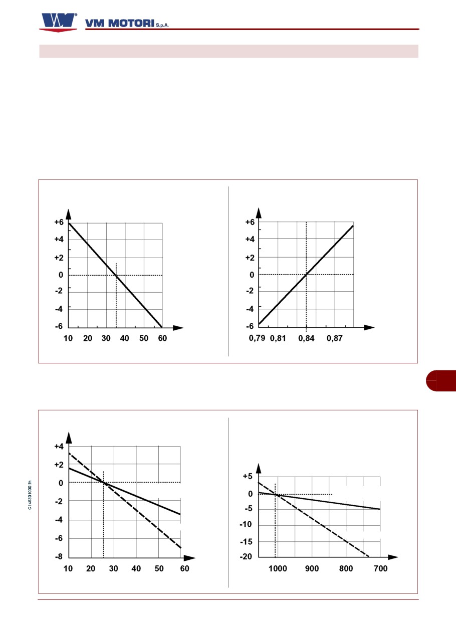
The engine performance is affected by fuel
The illustrations give indicative percentage
temperature, the temperature and relative
values for reduced engine output based on
humidity of incoming air and altitude.
fuel and air characteristics.
When using the engine at high altitudes and
For further information contact a VM MO-
high air and fuel temperatures, the output is
TORI S.P.A. assistance centre.
reduced.
Diagram of engine output based on fuel
Output variation (percentage) (%)
Output variation (percentage) (%)
Fuel temperature (°C)
Fuel density (kg/dm3)
IDM-45300902900.tif
GB
Diagram of engine output based on air
Output variation (percentage) (%)
Output variation (percentage) (%)
Supercharged and inter-
Supercharged and
cooled engine
intercooled engine
Aspirated engine
Aspirated engine
Air temperature (°C)
Air pressure (mbar)
IDM-45300903000.tif
English
- 33 -
Operating information
D700/750 E2-E3
ENGINE IGNITION AND TURNING OFF
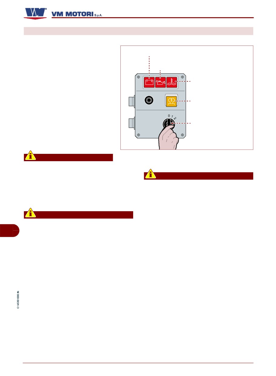
Starting the engine
1- Insert the key
(E) and turn it
Battery indicator (A)
clockwise to position 1.
All the warning lights come on, ex-
Engine oil indicator (B)
cept for coolant temperature warn-
ing light (C).
Coolant indicator (C)
The warning light (D) comes on to
signal the pre-heating phase of the
glowplugs.
Glow plugs indicator (D)
2-When the warning light (D) goes
off, turn the ignition key (E) clock-
Ignition key (E)
wise (pos. 2) to start the engine and
then release it.
All the warning lights go off.
IDM-45300902000.tif
Important
Turn the engine off
If the engine does not start imme-
diately, wait for 10-15 seconds before re-
Important
starting.
In the case of turbocharged engines, be-
3-Run the engine at a minimum speed dur-
fore switching the engine off it should be
ing the heating phase.
run at minimum idle speed for a few min-
utes in order to avoid damaging the tur-
bocharger.
Important
When the engine is running, indicator
Turn the ignition key (E) anticlockwise (pos.
GB
lights (red) might light up and/or a buzzer
0) to turn off the engine.
sound, to indicate the presence of a
All the warning lights go off.
fault. In these conditions, turn the engine
Remove the ignition key and store it in a
off immediately, then identify and elimi-
safe place known only to those in charge.
nate the cause of the fault (See "Trouble-
shooting").
English
- 34 -
Operating information
D700/750 E2-E3
REFUELLING
During refuelling, make sure the fuel does
not contain any residue; in this case use
Important
specific filters.
Do not use fuels with specifications oth-
er than those indicated.
Avoid using fuel mixed with water or other
substances which may damage the engine.
Danger - Attention
The engine has been designed to be pow-
All fuels are inflammable. Any fuel leak-
ered by standard fuels available on the Eu-
ing or dropping on hot surfaces and
ropean market (according to specifications
electric components can cause fires. Do
DIN EN 590). If it is to be powered by BI-
not smoke when refuelling or nearby any
ODIESEL fuels (according to specifications
filling station.
UNI EN 14214), it can be mixed, up to 5%,
with fuel available on the European market
(according to regulation DIN EN 590).
GB
English
- 35 -
Operating information
D700/750 E2-E3
MAINTENANCE INFORMATION
RECOMMENDATIONS FOR MAINTENANCE
Keep the equipment as much efficient as
terventions should follow all the precau-
possible and carry out the scheduled main-
tions needed to guarantee the safety of
tenance operations established by the man-
the people involved, in compliance with
ufacturer.
the requirements laid down in the appli-
cable legislation concerning safety at the
A good maintenance will ensure the highest
workplace.
performance, a longer operating lifetime
and a constant compliance with safety re-
quirements.
Important
For each maintenance operation, fill in
Warning - Caution
the "Periodic maintenance operation
record sheet" provided, so as to keep a
Unless otherwise stated, all interven-
trace of the operations performed and
tions should be carried out when the en-
therefore establish the most suitable
gine has been stopped, cooled down and
methods for future operations.
the ignition key has been removed.
Those authorized to carry out these in-
ENGINE MAINTENANCE
The maintenance operations are subdivided
considering that these parts need to be re-
into:
placed not only on the basis of their hours of
- Maintenance during running-in (first 50
operation but of ageing as well.
hours)
The approximate maximum time during
- Routine maintenance (after running-in)
which the chemical-physical characteristics
The frequency stated in the " routine main-
of a few components or lubricants are main-
tenance" table should be applied to engines
tained is stated below.
GB
which are used regularly.
- Lubricant oil: duration, 1 year
Some lubricants or components lose their
- Fuel filter cartridge: duration, 1 year
characteristics over time even if the engine
is left idle for long periods; therefore, main-
- Coolant: duration, 2 years
tenance intervals should be established
English
- 36 -
Maintenance information
D700/750 E2-E3
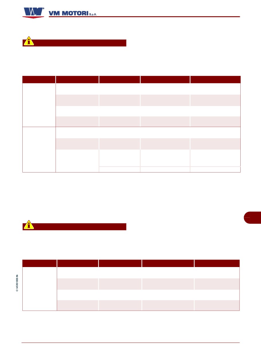
Maintenance during running-in table (first 50 hours)
Important
For each maintenance operation, fill in
trace of the operations performed and
the "Periodic maintenance operation
therefore establish the most suitable
record sheet" provided, so as to keep a
methods for future operations.
Frequency(1)
Component
Type of intervention
Intervention procedures
Reference
See “Engine oil level
Engine oil(2)
Level control
Top up, if necessary
control”
See “Engine coolant
Every 10
Coolant(4)
Level control
Top up, if necessary
level check”
hours
Clean with low pres-
(every day)
Air filter
Check it is clean
sure compressed air
Coolant fluid radia-
Check it is clean
Clean with a soft brush
tor
See “Engine oil
Engine oil(2)
Replacement
change”
After the first
See “Oil filter cartridge
Oil filter(3)
Replacement
50 hours (at
replacement”
the end of
See “How to adjust the
Checking the ten-
running-in)
Tension belts
tension of the driving
Transmission belt(5)
sion
belt”
Integrity control
Replace, if necessary
See “Belt replacement”
Routine maintenance table (after running-in)
GB
Important
For each maintenance operation, fill in
trace of the operations performed and
the "Periodic maintenance operation
therefore establish the most suitable
record sheet" provided, so as to keep a
methods for future operations.
Frequency(1)
Component
Type of intervention
Intervention procedures
Reference
See “Engine oil level
Engine oil(2)
Level control
Top up, if necessary
control”
See “Engine coolant
Coolant(4)
Level control
Top up, if necessary
Every 10
level check”
hours
Clean with low pressure
Air filter
Check it is clean
compressed air
Coolant fluid radia-
Check it is clean
Clean with a soft brush
tor
English
- 37 -
Maintenance information
D700/750 E2-E3
Frequency(1)
Component
Type of intervention
Intervention procedures
Reference
See “How to adjust
Checking the ten-
Tension belts
the tension of the dri-
Every 150
Transmission
sion
ving belt”
hours
belt(5)
See “Belt replace-
Integrity control
Replace, if necessary
ment”
See “Engine oil
Engine oil(2)
Replace
change”
Replace the cartri-
See “Oil filter cartri-
Oil filter(3)
dge
dge replacement”
Every 300
See “Fuel filter repla-
hours(6)
Fuel filter(3)
Replace
cement”
See "Control screw
Fuel circuit unions
Check tightening
tightening and union
sealing"
See “Coolant repla-
Coolant(4)
Replace
cement”
Air filter
Replace
Every 500
Injector setting
Apply to an authori-
hours
Check the pressure
pressure
sed workshop
Preheating glow
Check integrity of
Apply to an authori-
plugs
components
sed workshop
Transmission
See “Belt replace-
Every 1000
Replace
belt(5)
ment”
hours
Fuel tank
Clean
Every 4000
Performing partial
Apply to an authorised
Engine
hours
overhaul
workshop
Every 8000
Performing general
Apply to an authorised
Engine
hours
overhaul
workshop
(1) If an hour counter is not available, the frequency of the interventions should be calculated on the basis of a calendar
day: one calendar day corresponds to 12 hours of operation.
(2) In severe working conditions, such as dusty environments and operation at extreme loads, the engine oil must be
changed every 150 working hours. If the engine has not been in operation for the length of time indicated, the oil must
still be changed at least once a year.
(3) If the engine has not been in operation for the length of time indicated, the filter must still be changed at least once
every 12 months.
GB
(4) If the engine has not been in operation for the length of time indicated, the fluid must still be changed at least once
every 24 months.
(5) If the engine has not been in operation for the length of time indicated, the belt must still be changed at least once
every 24 months.
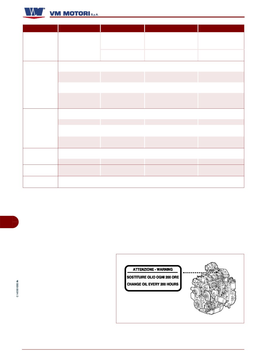
(6) In engine D754SE3, TE3, IE3 models with a low capacity oil sump, a special plate is applied on the cover of the
engine valves to indicate that the engine oil and the oil filter must be changed every 200 hours instead of every 300.
IDM-45300903200.tif
English
- 38 -
Maintenance information
D700/750 E2-E3
Periodic maintenance operation record sheet
Important
For each maintenance operation, fill in
lish the most suitable methods for future
the sheet, so as to keep a trace of the op-
operations.
erations performed and therefore estab-
Signature and stamp of
Datt
Hours (1)
Type of maintenance performed
workshop
_____
_____
_____________________________________
________________
_____
_____
_____________________________________
________________
GB
_____
_____
_____________________________________
________________
_____
_____
_____________________________________
________________
(1) Indicate the total number of working hours.
English
- 39 -
Maintenance information
D700/750 E2-E3
Signature and stamp of
Datt
Hours (1)
Type of maintenance performed
workshop
_____
_____
_____________________________________
________________
_____
_____
_____________________________________
________________
_____
_____
_____________________________________
________________
GB
_____
_____
_____________________________________
________________
_____
_____
_____________________________________
________________
(1) Indicate the total number of working hours.
English
- 40 -
Maintenance information
D700/750 E2-E3
Signature and stamp of
Datt
Hours (1)
Type of maintenance performed
workshop
_____
_____
_____________________________________
________________
_____
_____
_____________________________________
________________
_____
_____
_____________________________________
________________
GB
_____
_____
_____________________________________
________________
_____
_____
_____________________________________
________________
(1) Indicate the total number of working hours.
English
- 41 -
Maintenance information
D700/750 E2-E3
Signature and stamp of
Datt
Hours (1)
Type of maintenance performed
workshop
_____
_____
_____________________________________
________________
_____
_____
_____________________________________
________________
_____
_____
_____________________________________
________________
GB
_____
_____
_____________________________________
________________
_____
_____
_____________________________________
________________
(1) Indicate the total number of working hours.
English
- 42 -
Maintenance information
D700/750 E2-E3
MAINTENANCE WHEN THE ENGINE IS LEFT IDLE
If the vehicle/equipment to which the engine
is fitted remains inactive, certain mainte-
Important
nance operations must be carried out to en-
It is advisable to start the engine bring-
sure the engine remains in full working
ing it to the operating temperature
order.
(70÷80°C) at least once per month. The
engine must be started once per month if
If the engine is not used for short periods of
it is installed for emergency purposes.
time, carry out the following interventions:
1- Make sure the electric contacts are
If the engine is left idle for prolonged peri-
working properly and, if necessary, protect
ods, carry out the engine protective treat-
them with an anti-oxidant spray.
ment to guarantee its efficiency for 6 months
and to avoid continuous control and mainte-
- Check the charge of the battery and the
nance interventions. If the engine is not
liquid level.
used for a further period of time, check the
need to repeat the protective treatment for
- If necessary, carry out the scheduled
other
6 months (See "Engine protective
maintenance work (See "Engine mainte-
treatment").
nance").
ENGINE PROTECTIVE TREATMENT
Follow the procedure below.
6-Turn off the engine and remove the igni-
1- Check the engine oil and coolant level.
tion key.
2-Fill the service tank with a mixture made
7-Let the engine cool down adequately to
up of 10% protective oil (Castrol Safecoat
avoid being burnt.
DW30X, Rustilo 181, Rustilo DWX31) and
8-Protect the electric contacts with an anti-
GB
90% fuel.
oxidant spray.
Important
9-Protect the engine with waxes and/or a
This operation can be carried out using
synthetic resin anti-oxidant spray.
an additional tank fitted with couplings
10- Disconnect the terminals of the battery.
connecting it to the engine fuel supply
circuit.
11- Fill up the fuel tank.
3-Disconnect all the mechanical parts and
12- Loosen the transmission belt to guaran-
auxiliary applications from the engine as they
tee it a longer life (See "How to adjust the
could be damaged by running it at no-load.
tension of the driving belt")
4-Start the engine and run it at minimum
13- Make sure the engine is sheltered from
speed for 5 minutes.
weather agents.
5-Bring the engine to 1500÷1800 rpm for
15 minutes until the operating temperature
(70÷80°C) is reached.
English
- 43 -
Maintenance information
D700/750 E2-E3
MAINTENANCE IN CASE OF ENGINE INACTIVITY
After a period of inactivity, it is necessary to
- Replace the air filter according to the es-
carry out a few maintenance interventions
tablished intervals
(See "Routine mainte-
before starting the engine again to ensure
nance table (after running-in)").
its maximum efficiency conditions.
- Tension again the transmission belt (See
- Check the charge of the battery and the
"How to adjust the tension of the driving
liquid level.
belt").
- Make sure the electric contacts are intact
- Check the tightening of the hydraulic un-
and properly working.
ions (See "Control screw tightening and un-
ion sealing").
- Carry out the operation diagnosis of the
engine.
- Check the rubber gaskets and relevant
fixing clips to ensure they are undamaged.
- Check the oil level, and, if necessary, top
up or replace it according to the established
- Use a cloth soaked in a degreasing prod-
intervals (See "Routine maintenance table
uct to remove the external protective treat-
(after running-in)").
ment.
- Replace the oil filter according to the es-
- Start the engine and run it at minimum
tablished intervals
(See "Routine mainte-
speed for a few minutes (See "Engine igni-
nance table (after running-in)").
tion and turning off").
- Check the coolant level, and if neces-
- If no anomalies are detected, bring the
sary, top up or replace it according to the es-
engine to its operating temperature
tablished
intervals
(See
"Routine
(70÷80°C).
maintenance table (after running-in)").
- Turn off the engine and check again the
GB
- Replace the fuel filter according to the es-
engine oil and coolant level.
tablished intervals
(See "Routine mainte-
nance table (after running-in)").
WASHING THE ENGINE
To avoid irreversible damage to the electric
When you have finished washing the en-
and electronic components of the engine,
gine, take out all the electric connectors,
do not point jets of high pressure water or
blow compressed air to eliminate any water,
jets of steam at these components. Pay par-
and apply a specific product to prevent oxi-
ticular attention to the joins of the cables, the
dation and corrosion.
electric connectors, the alternator and the
When you have finished washing, start the
starter motor, protecting them adequately if
engine and leave it running for a few min-
necessary.
utes so that it gets completely dry.
Before washing the engine, adequately pro-
tect the fuel supply pump so as not to dam-
age it with water infiltrations.
English
- 44 -
Maintenance information
D700/750 E2-E3
CHECKS AND CONTROLS
The list indicates some of the maintenance,
testing and control operations to be carried
Important
out on the engine during normal operation.
For each maintenance operation, fill in
- Fuel supply circuit bleeding
the "Periodic maintenance operation
- Control screw tightening and union sealing
record sheet" provided, so as to keep a
- Engine oil level control
trace of the operations performed and
- Engine coolant level check
therefore establish the most suitable
methods for future operations.
- Engine oil change
- Coolant replacement
- Oil filter cartridge replacement
– Fuel filter replacement.
FUEL SUPPLY CIRCUIT BLEEDING
The operation must be carried out every
time the fuel filter is changed, following one
of the listed procedures, according to the
engine model.
Warning - Caution
To avoid fire risk due to fuel leakage or
discharge, ALWAYS carry out this oper-
ation when the engine is off and cold.
Engines equipped with single injection
pump
Follow the procedure below.
GB
1- Turn off the engine and remove
the ignition key.
2-Let the engine cool down ade-
quately to avoid being burnt.
3-Prepare a container of appropri-
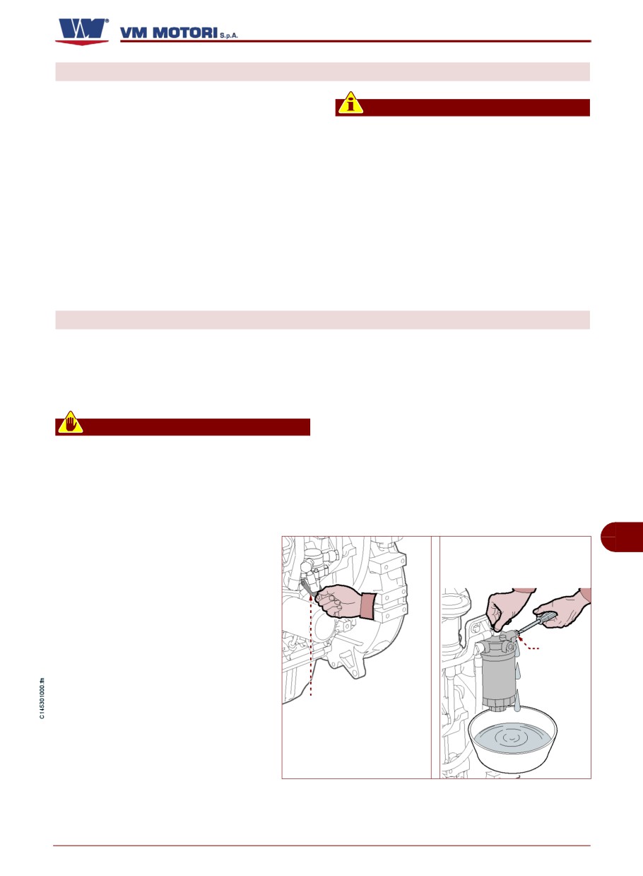
Screw (A)
ate capacity.
4-Loosen the screw (A).
Membrane pump
5-Operate the pump (B) manually
(B)
to eliminate air from the circuit.
Interrupt the operation only when
all air has been discharged.
IDM-45300902100.tif
6-Tighten the screw (A).
English
- 45 -
Maintenance information
D700/750 E2-E3
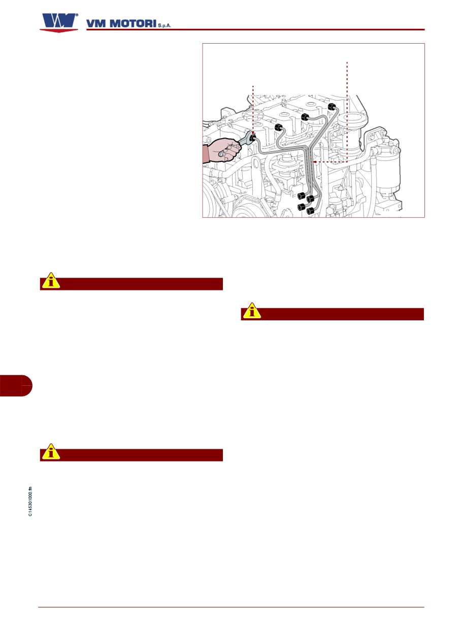
7-Loosen fittings (C).
Fuel supply hoses
8-Rotate engine ignition key to po-
sition 1 to allow the opening of sole-
Connector (C)
noid of the pump.
9-Rotate and keep ignition key in
position 2 (the engine rotates idle) to
discharge the air from the pump and
from feeding pipes.
Release ignition key when the
fuel comes out of feeding pipes.
10-Tighten fittings (C).
11-Wipe out the fuel residues be-
IDM-45300902200.tif
fore starting the engine.
12-Start the engine and run it at minimum
3-Prepare a container of appropriate ca-
speed for a few minutes.
pacity.
4-Completely fill new filter with fuel (with a
Important
container).
In case the engine does not start, repeat
the described procedure and, if neces-
Important
sary, contact an Assistance Centre au-
Use clean and impurity-free fuel.
thorised by the manufacturer.
5-Install fuel filter in the special seat (See
13-Stop the motor when you finish this op-
"Fuel filter replacement.").
eration.
6-Loosen fittings (C).
Engines equipped with rotating injection
GB
pump
7-Rotate engine ignition key 1 to position
The operation must be carried out only by
to allow the opening of solenoid of the
means of the battery-operated starter mo-
pump.
tor.
8-Rotate and keep ignition key in position
2 (the engine rotates idle) to discharge the
Important
air from the pump and from feeding pipes.
To avoid problems, before carrying out
Release ignition key (C) when the fuel
the operation, make sure that the batter-
comes out of feeding pipes.
ies have a suitable state of charge.
1- Turn off the engine and remove the igni-
9-Wipe out the fuel residues before start-
tion key.
ing the engine.
2-Let the engine cool down adequately to
10- Start the engine and run it at minimum
avoid being burnt.
speed for a few minutes.
English
- 46 -
Maintenance information
D700/750 E2-E3
cal assistance centre that is authorised
Important
by the manufacturer.
In case the engine does not start, try to
11- Stop the motor when you finish this op-
restart it without insisting too much in
eration.
order not to damage the starter motor.
If the problem persists, contact a techni-
CONTROL SCREW TIGHTENING AND UNION SEALING
Follow the procedure below.
4-Make sure the fixing screws of the main
1- Start the engine and run it at minimum
parts are tightened properly.
speed for a few minutes.
5-Check the union sealing on the fuel sup-
2-Run the engine at normal speed until the
ply circuit.
operating temperature
(70÷80°C) is
6-Check the tightening of the clamps.
reached.
7-Check any fluid leaks.
3-Turn off the engine and let it cool down.
ENGINE OIL LEVEL CONTROL
Follow the procedure below.
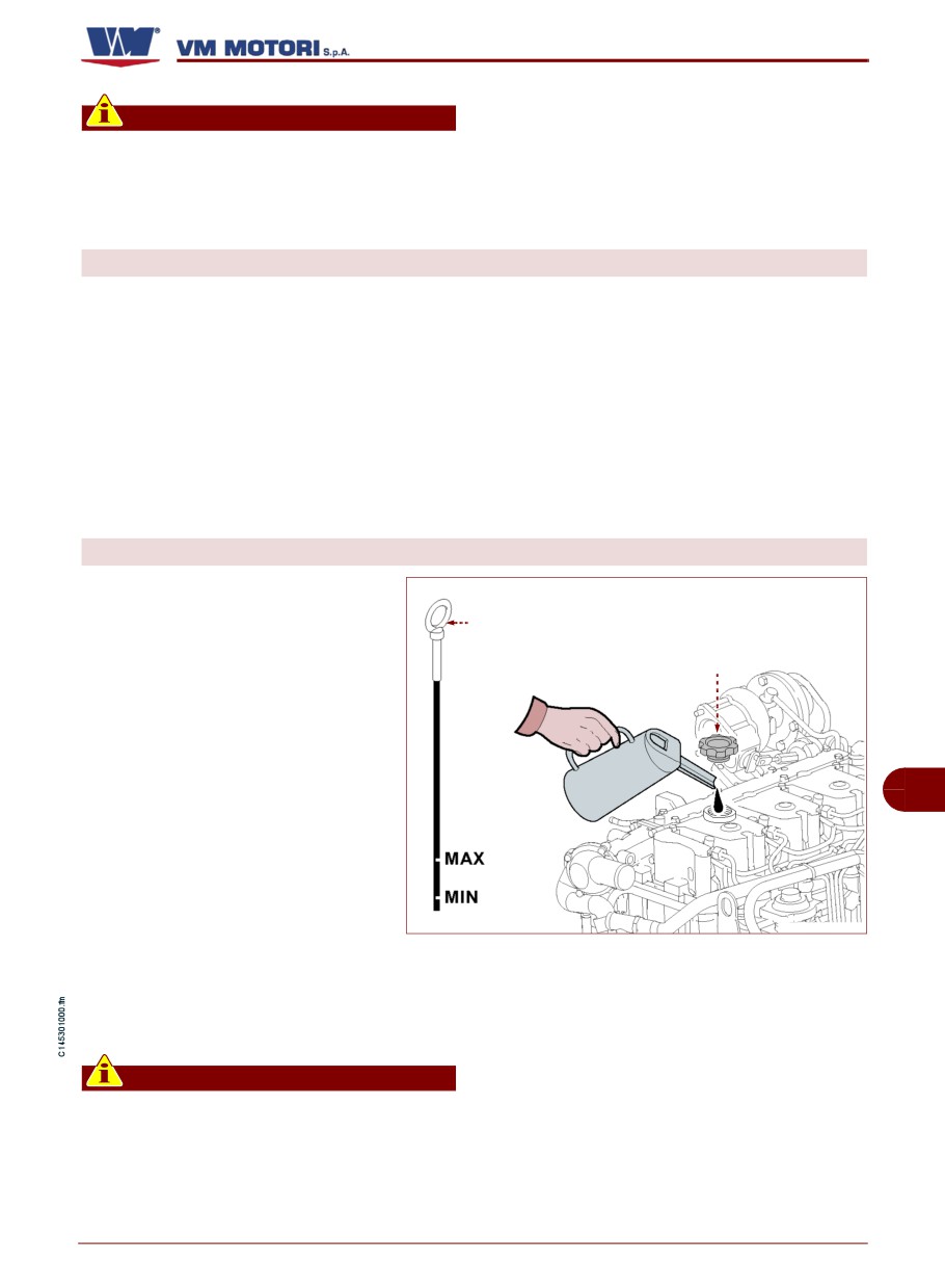
1- Start the engine and bring it to the
Dipstick (L)
operating temperature (70÷80 °C).
Filler cap (M)
2-Turn off the engine and remove
the ignition key.
3-Place the engine on a perfectly
level surface.
GB
4-Wait a few minutes so that all
the oil will flow into the sump.
5-Remove the dipstick (L) and
check the oil level.
IDM-45300901100.tif
6-Top up, if necessary, from plug
(M). When topping up the oil, to
avoid exceeding the maximum allowed val-
ue, add the oil in small amounts (100 to 200
ml at a time) until it reaches the correct level.
Important
The oil level should be included between
the minimum and maximum marks.
Do not mix oils of different brands or
with different features
(See "Recom-
mended lubricants").
English
- 47 -
Maintenance information
D700/750 E2-E3
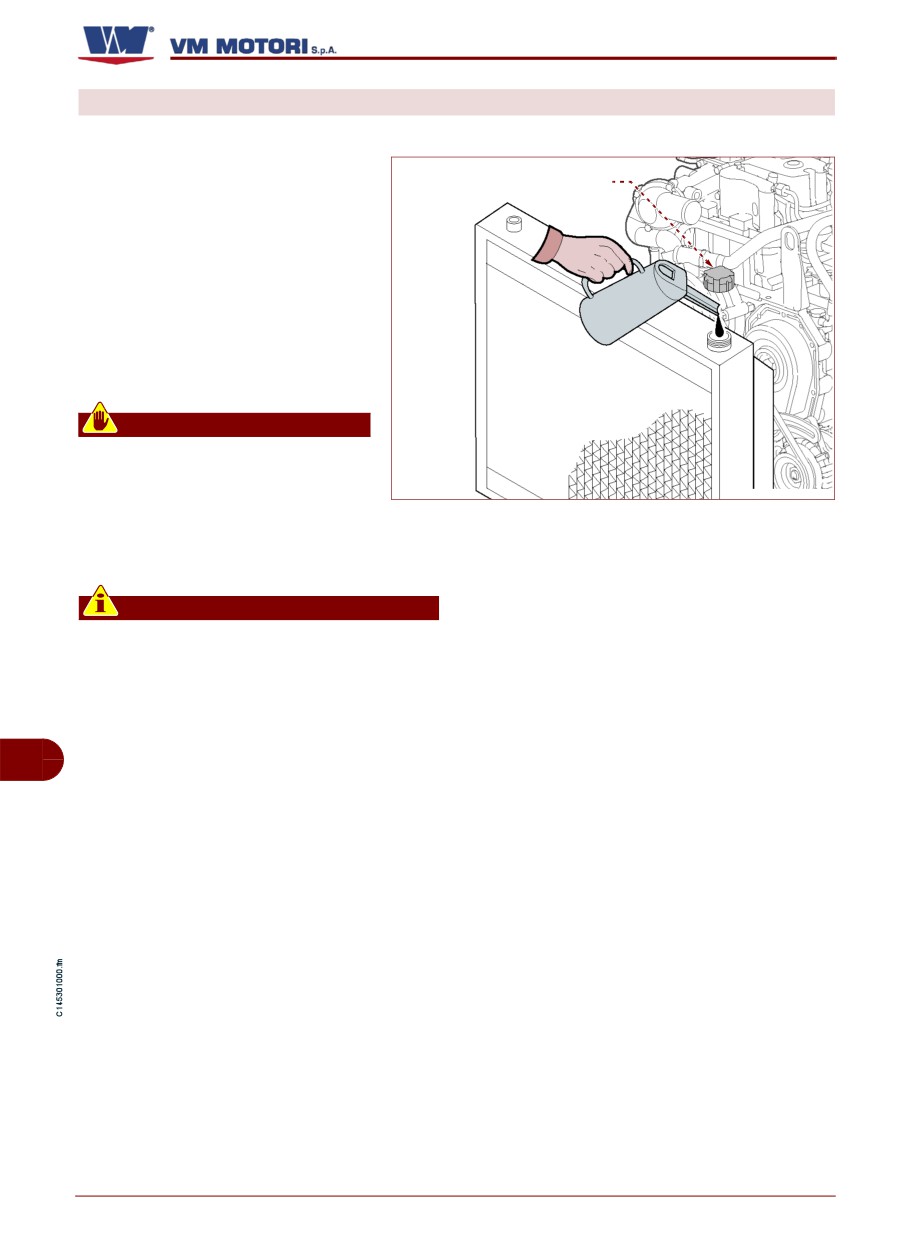
ENGINE COOLANT LEVEL CHECK
Follow the procedure below.
1- Start the engine and bring it to
Filler cap (P)
the
operating
temperature
(70÷80 °C).
2-Turn off the engine and remove
the ignition key.
3-Let the engine cool down prop-
erly.
4-Unscrew the plug (P).
Warning - Caution
Open the plug gently to drain the
pressure.
IDM-45300901200.tif
5-Top up, if necessary, from plug
(P). (As for the liquid quantity and type, see
"Technical data").
Important
- When topping up, only use a mixture
with the same composition as the one al-
ready contained in the engine cooling
system.
- The fluid level must be up to the base
GB
of the neck into which the radiator plug is
screwed.
- For further information, please con-
sult the documentation provided by the
manufacturer of the vehicle/device in
which the engine is installed.
English
- 48 -
Maintenance information
D700/750 E2-E3
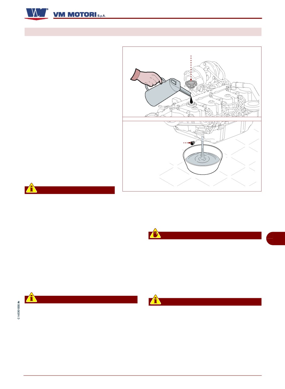
ENGINE OIL CHANGE
Follow the procedure below.
1- Turn off the engine and remove
Filler cap (P)
the ignition key.
2-Let the engine cool down ade-
quately to avoid being burnt.
3-Prepare a container of appro-
priate capacity.
As for the oil quantity, see "Techni-
cal data".
4-Unscrew the plug (P).
5-Unscrew the exhaust plug (Q)
and let all the oil flow into the con-
Discharge cap (Q)
tainer.
6-Replace the gasket and screw
plug (Q) back into place.
Important
IDM-45300901400.tif
Lock the plug to a torque of 55
Nm.
9-Start the engine and bring it to the oper-
ating temperature (70÷80 °C).
7-Pour the new oil through the filling plug
Check for any oil leaks
(P).
To reach the correct engine oil level, add the
Warning - Caution
minimum oil quantity depending on the en-
GB
In the event of oil leaks, check the level
gine model (see “Technical data").
periodically to evaluate the extent of the
Then top up.
leak. If the amount is excessive, contact
When topping up the oil, to avoid exceeding
one of the manufacturer's authorised
the maximum allowed value, add the oil in
service centres.
small amounts (100 to 200 ml at a time) until
it reaches the correct level.
10- Turn off the engine and check the oil level.
Important
Important
The oil level must be between the mini-
- Do not throw the oil in the environ-
mum and maximum marks on the dip-
ment but carry out its disposal in compli-
stick.
ance with legislation in force in the
country where it is used.
8-Screw again the plug (P).
- Use the oils and lubricators recom-
mended by the manufacturer (See "Rec-
ommended lubricants").
English
- 49 -
Maintenance information
D700/750 E2-E3
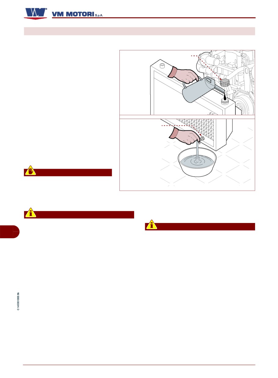
COOLANT REPLACEMENT
Follow the procedure below.
1- Start the engine and run it at
minimum speed for a few minutes.
Filler cap (P)
The cooling circuit reaches the op-
erating pressure.
2-Turn off the engine and remove
the ignition key.
3-Let the engine cool down ade-
quately to avoid being burnt.
4-Prepare a container of appro-
Tap (S)
priate capacity.
As for the liquid quantity, see
"Technical data".
5-Unscrew the load plug (P).
Warning - Caution
Open the plug gently to drain the
pressure.
IDM-45300901500.tif
6-Open the cock (S).
8-Close the cock (S).
9-Pour in the new liquid.
Important
- In the absence of a coolant discharge
Important
tap, check for the presence of a dis-
GB
- The fluid level must be up to the base
charge plug or loosen one of the cooling
of the neck into which the radiator plug is
circuit clamps in the lower part of the
screwed.
cooler.
- If there is a coolant expansion tank,
- For further information, please con-
consult the documentation provided by
sult the documentation provided by the
the manufacturer of the vehicle/device in
manufacturer of the vehicle/device in
which the engine is installed.
which the engine is installed.
- As for the liquid quantity and type, see
7-Let the liquid flow into the container.
"Technical data".
10- Screw again the plug (P).
English
- 50 -
Maintenance information
D700/750 E2-E3
11-Turn the engine on and keep it running
13- Check the coolant level and, if neces-
at idle speed for a few minutes to bring it up
sary, carry out topping-up
(See "Engine
to working temperature (70÷80°C).
coolant level check").
Important
Important
If the coolant level drops, top up as need-
Do not throw away any polluting material
ed
in the environment. Carry out their dis-
posal in compliance with the relevant
12-Turn off the engine and let it cool down
legislation in force.
properly.
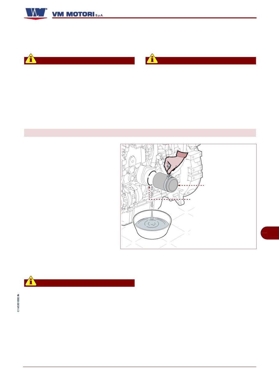
OIL FILTER CARTRIDGE REPLACEMENT
Follow the procedure below.
1- Turn off the engine and remove
the ignition key.
2-Let the engine cool down ade-
quately to avoid being burnt.
Oil filter (U)
3-Prepare a container to collect
any leak.
Gasket (V)
4-Unscrew filter (U) and replace
it.
5-Check the conditions of gasket
GB
(V) and, if necessary, replace it.
6-Lubricate the seal of the new
IDM-45300901600.tif
cartridge before assembling it.
9-Turn off the engine and remove the igni-
7-Install the oil filter.
tion key.
10- Wait a few minutes so that all the oil will
Important
flow into the sump.
Lock the screw to a torque of 12,7 Nm.
8-Turn the engine on and leave it running
at minimum speed for a few minutes until it
reaches working speed (70÷80°C).
English
- 51 -
Maintenance information
D700/750 E2-E3
11-Check that the oil level is correct and top
Warning - Caution
up if necessary.
In the event of oil leaks, check the level
When topping up the oil, to avoid exceeding
periodically to evaluate the extent of the
the maximum allowed value, add the oil in
leak. If the amount is excessive, contact
small amounts (100 to 200 ml at a time) until
one of the manufacturer's authorised
it reaches the correct level.
service centres.
Important
Important
The oil level must be between the mini-
mum and maximum marks on the dipstick.
Do not throw away any polluting material
in the environment. Carry out their dis-
12-Check for any oil leaks
posal in compliance with the relevant
legislation in force.
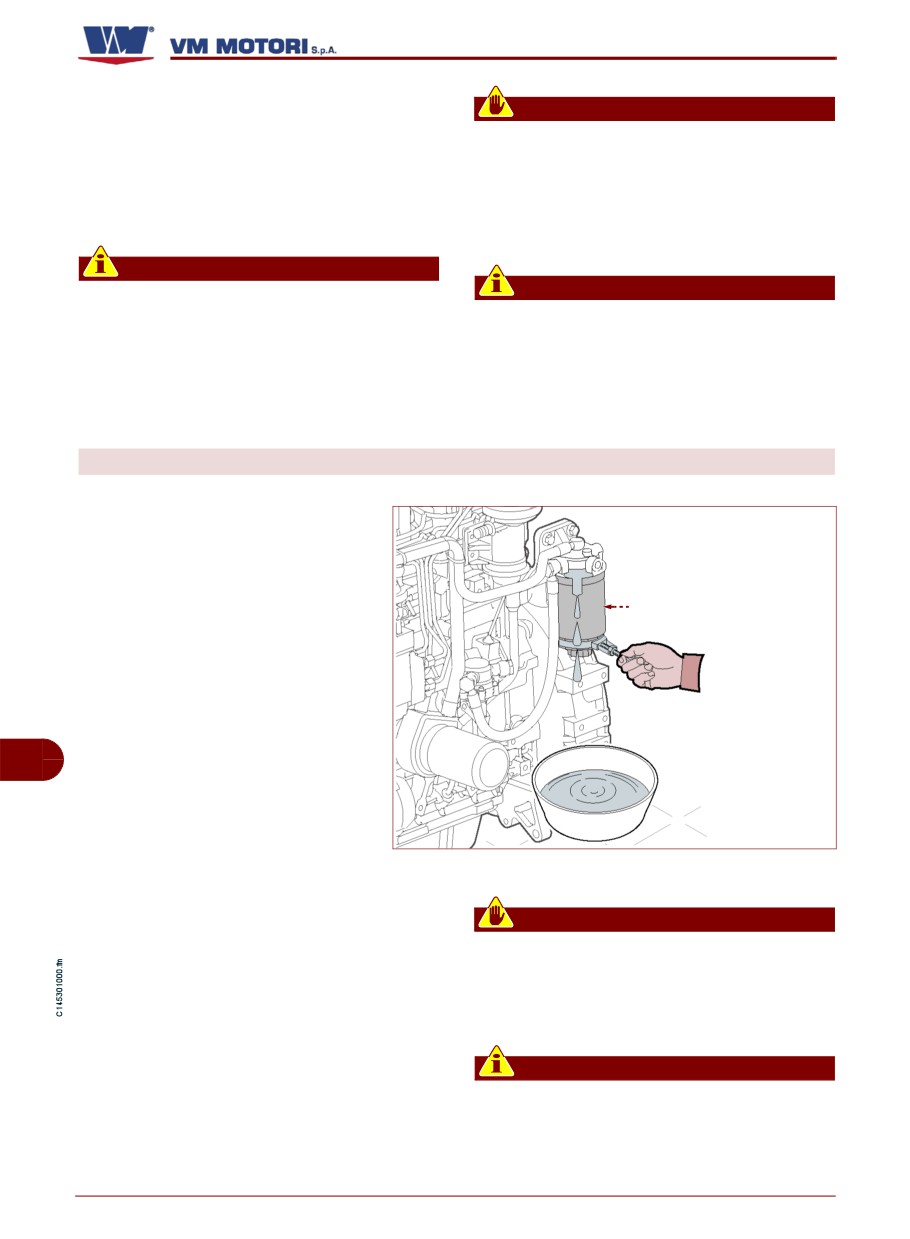
FUEL FILTER REPLACEMENT
Follow the procedure below.
1- Turn off the engine and remove
the ignition key.
2-Let the engine cool down ade-
quately to avoid being burnt.
Fuel filter (Z)
3-Prepare a container to collect
any leak.
4-Remove the filter (Z) using the
tool provided.
GB
5-Fill the new filter with the fuel
from the filter being replaced.
6-Lubricate the gasket of the new
IDM-45300901700.tif
filter before mounting it.
7-Fit the new filter using the tool provided.
Warning - Caution
8-Bleed air from the fuel supply circuit
In the event of fuel leaks, identify and elimi-
(See "Fuel supply circuit bleeding").
nate the cause.
9-Turn the engine on and check for any
If the problem persists, contact one of the
fuel leaks.
manufacturer's authorised service centres.
Important
Do not throw away any polluting material
in the environment. Carry out their dis-
posal in compliance with the relevant
legislation in force.
English
- 52 -
Maintenance information
D700/750 E2-E3
RECOMMENDED LUBRICANTS
Oils of different brands can be used
provided that they have the follow-
ing features:
IDM-45300302500.tif
D700E2
D700E3
Viscosity grade
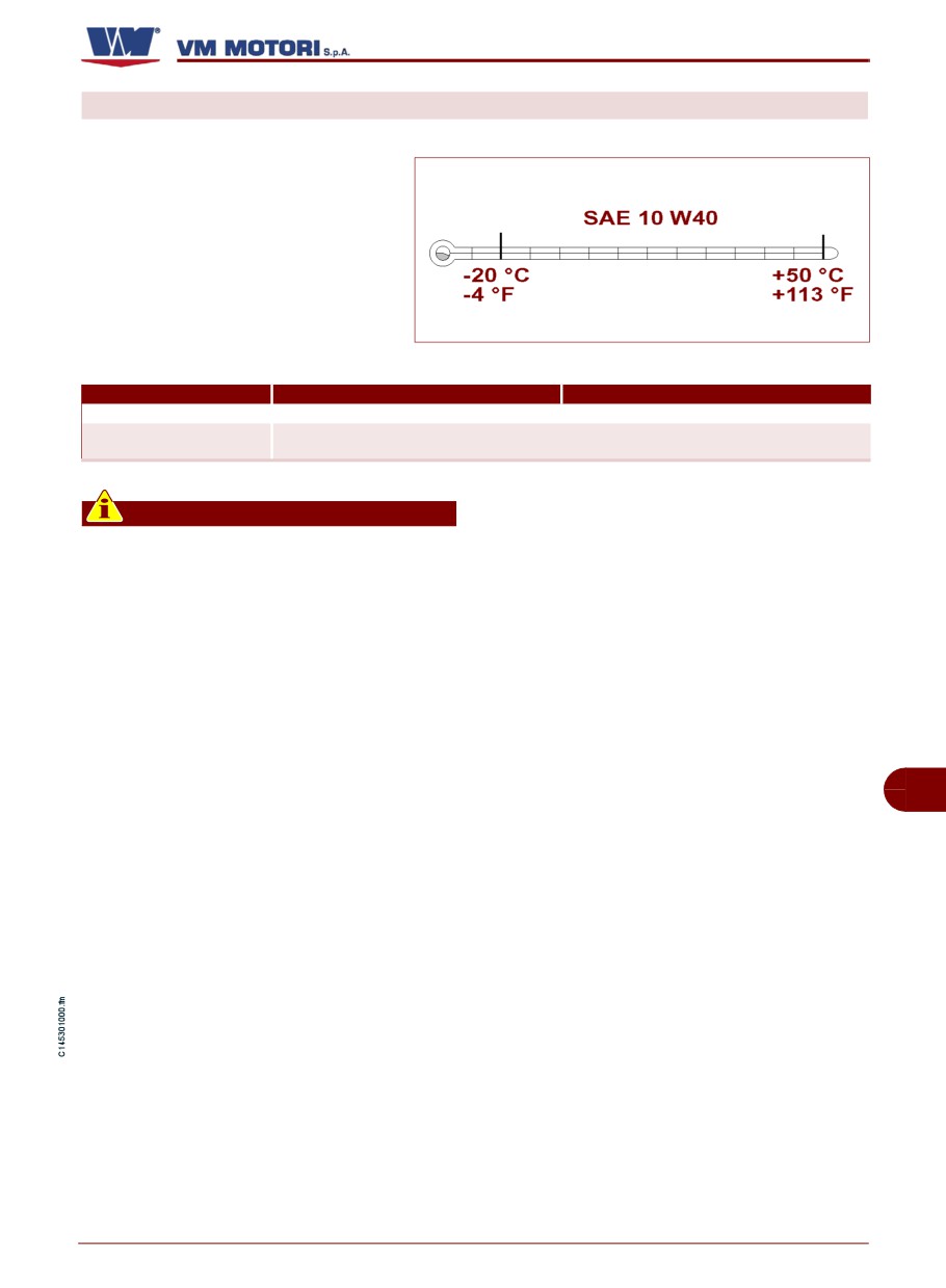
SAE10W-40 (-20°C - +50°C)
ACEA A3/B4
Minimum specifications
API CG-4, CH-4, CI-4
Important
It is advisable not to mix oils with differ-
ent characteristics.
Classification SAE
Oils are classified according to their viscos-
maximum operating temperature of the en-
ity and use: winter or summer. The symbol
gine.
W (=Winter) identifies oils intended for win-
The illustration shows the minimum and
ter use. When choosing oils for winter use,
maximum operating temperature of SAE
bear in mind the minimum ambient temper-
10W-40 grade oil.
ature at which the engine must operate. In
the case of summer oils, bear in mind the
GB
English
- 53 -
Maintenance information
D700/750 E2-E3
INFORMATION ABOUT FAILURES
TROUBLESHOOTING
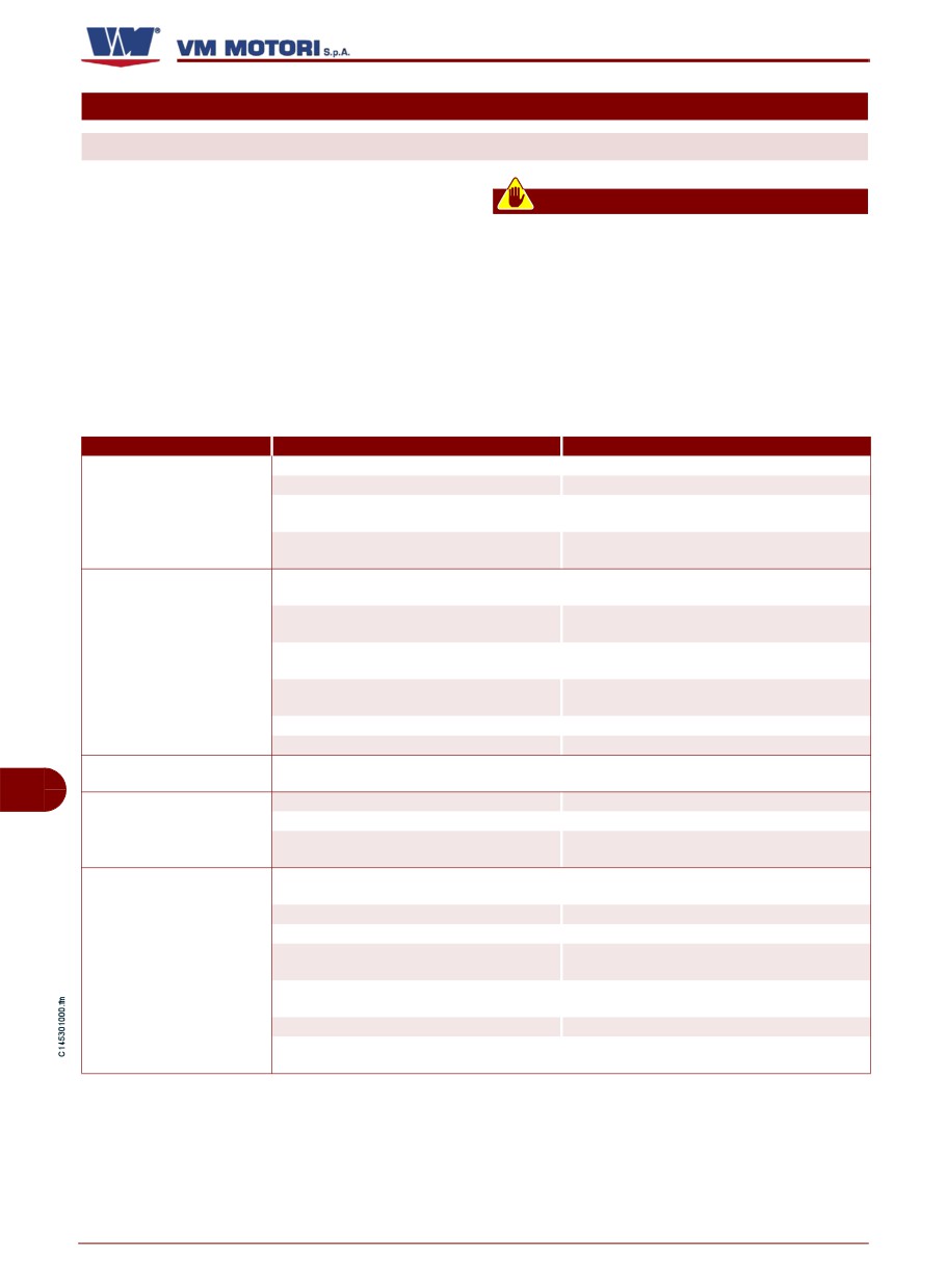
The information below are provided to facil-
Warning - Caution
itate the identification and solution of possi-
ble anomalies and failures which may occur
Activation of a visual and/or acoustic
signal indicates some form of malfunc-
during operation. Some of these problems
can be solved by the user, while others re-
tion. In this case, turn the engine off im-
mediately
and
consult
the
quire specific technical skills or abilities,
therefore they should be exclusively dealt
documentation supplied by the manufac-
turer of the vehicle/device in which the
with by qualified technicians with extensive
experience in the specific sector of interven-
engine is installed.
tion.
Problem
Cause
Remedy
Flat battery
Recharge or replace battery
Blown fuse
Replace fuse
During the ignition pha-
The electric cables are disconnected or
se the control board and
Check the electric connections
they do not guarantee continuity
the engine do not start.
Replace the sensor
Failure of engine revolution sensor
Apply to an authorised workshop
Carry out bleeding (See “Fuel supply circuit
Presence of air in the fuel supply circuit
bleeding”).
Replace the injectors.
Dirty or faulty injectors
Apply to an authorised workshop
The engine does not
Replace the valve.
Faulty fuel pressure regulation valve
start
Apply to an authorised workshop.
Replace the start control.
Failure of the start control
Apply to an authorised workshop
Water and/or impurities in the fuel
Apply to an authorised workshop
Clogged fuel filter
Replace filter (See “Fuel filter replacement”)
The starter motor runs
Check the starter motor.
Electromagnet failure
idle
Apply to an authorised workshop
GB
Flat battery
Recharge or replace battery
The starter motor is not
Interrupted electric connection
Check the electric connections
running
Replace the worn brushes.
Worn brushes
Apply to an authorised workshop
Carry out bleeding (See “Fuel supply circuit
Presence of air in the fuel supply circuit
bleeding”)
Clogged fuel filter
Replace filter (See “Fuel filter replacement”)
Injection pump malfunction
Apply to an authorised workshop
Replace the valve.
The engine stops after
Faulty fuel pressure regulation valve
Apply to an authorised workshop
ignition
Carry out bleeding (See “Fuel supply circuit
Presence of air in the fuel supply circuit
bleeding”).
Water and/or impurities in the fuel
Apply to an authorised workshop
The electric cables are disconnected or
Check the electric connections
they do not guarantee continuity
English
- 54 -
Information about failures
D700/750 E2-E3
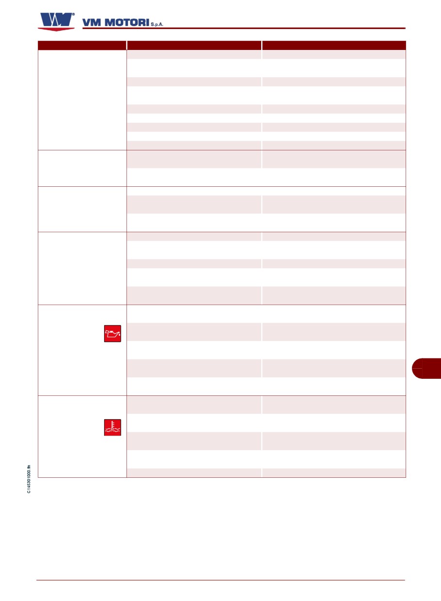
Problem
Cause
Remedy
Clogged fuel filter
Replace filter (See “Fuel filter replacement”)
Carry out bleeding (See “Fuel supply circuit
Presence of air in the fuel supply circuit
bleeding”)
Injection pump malfunction
Apply to an authorised workshop
Replace the injectors.
The engine does not rea-
Dirty or faulty injectors
Apply to an authorised workshop
ch the operating speed
Water and/or impurities in the fuel
Apply to an authorised workshop
Clogged air filter
Clean or replace the filter
Insufficient combustion air flow
Apply to an authorised workshop
Engine overheating
Apply to an authorised workshop
Overload
Reduce the load
Replace the injectors.
Dirty or faulty injectors
Emission of black smo-
Apply to an authorised workshop
ke from the exhaust pipe
Replace the turbine.
Faulty turbocharging turbine
Apply to an authorised workshop
Oil level too high
Adjust the oil level
Light emission of white
Check compression.
Worn segments
smoke from the exhaust
Apply to an authorised workshop
pipe
Check wear.
Worn valve guideways
Apply to an authorised workshop
Burnt gasket head
Apply to an authorised workshop
Replace the pump.
Water pump malfunction
Apply to an authorised workshop
Abundant emission of
Replace the belt
See “Belt replacement”
white smoke from the
Replace the valve.
exhaust pipe
Thermostat valve malfunction
Apply to an authorised workshop
Top up, if necessary (See “Fuel supply circuit
Coolant too low
bleeding”)
Check or replace the pressure gauge.
Failure of pressure gauge
Apply to an authorised workshop
The
pressure
Adjust the oil level (See “Engine oil level con-
gauge shows a
Oil level too low
trol”)
too low engine
Check or replace the pump.
oil pressure and
Oil pump failure
Apply to an authorised workshop
the correspon-
Check and, if appropriate, replace the sensor.
ding warning li-
Faulty sensor
GB
ght comes on
Apply to an authorised workshop
Replace the engine oil filter (See “Oil filter
Engine oil filter blocked
cartridge replacement”)
Adjust the engine coolant level (See “Engine
Coolant too low
coolant level check”)
The coolant tem-
Stucked overpressure valve of the load
perature
war-
Replace the plug
plug
ning light comes
Replace the pump.
on
Water pump malfunction
Apply to an authorised workshop
Replace the valve.
Thermostat valve malfunction
Apply to an authorised workshop
Broken or worn belt
Replace the belt (See “Belt replacement”)
English
- 55 -
Information about failures
D700/750 E2-E3
Problem
Cause
Remedy
Clogged fuel filter
Replace filter (See “Fuel filter replacement”)
Carry out bleeding (See “Fuel supply circuit
Presence of air in the fuel supply circuit
bleeding”)
Replace the pump.
Injection pump malfunction
Apply to an authorised workshop
Output reduction
Replace the injectors.
Dirty or faulty injectors
Apply to an authorised workshop
Clogged air filter
Clean or replace the filter
Engine overheating
Apply to an authorised workshop
Insufficient combustion air flow
Apply to an authorised workshop
The battery war-
Check and, if appropriate, replace the alter-
The alternating current generator does
ning light comes
nating current generator.
not charge the battery
on
Apply to an authorised workshop
The oil pressure
warning light co-
Engine oil pressure too low
Apply to an authorised workshop
mes on
GB
English
- 56 -
Information about failures
D700/750 E2-E3
INFORMATION ABOUT COMPONENT REPLACEMENT
RECOMMENDATIONS FOR PART REPLACEMENT
Before carrying out any replacement, acti-
damages to people or components resulting
vate all safety devices and evaluate the
from the use of non original spare parts and
need to inform the personnel working on the
from repairs carried out without the authori-
engine or nearby. In particular, place proper
sation of the manufacturer.
signs in the nearby areas and keep away all
When requesting spare parts, always con-
devices which, once activated, may repre-
tact your nearest VM MOTORI S.P.A. spare
sent a source of unexpected danger and
parts dealer
(see "enclosed documenta-
risk for people's safety and health. When
tion": Spare parts and service centre ad-
necessary, replace the worn components,
dress booklet) and indicate the engine's
and use original spare parts only. The man-
serial number (See "Manufacturer and en-
ufacturer cannot be held responsible for
gine identification").
BELT REPLACEMENT
Follow the procedure below.
1- Turn off the engine and remove
the ignition key.
Nut (A)
2-Let the engine cool down ade-
quately to avoid being burnt.
3-Adjust nut
(A) to loosen the
GB
transmission belts.
4-Remove the belt(B) and replace
it.
Belt (B)
5-Tighten the belt (See "How to
IDM-45300901800.tif
adjust the tension of the driving
belt").
Important
- Before restarting the engine, make
sure there are no tools or other material
left near the moving parts.
- Do not throw away any replaced part
in the environment. Carry out their dis-
posal in compliance with the relevant
legislation in force.
English
- 57 -
Information about component replacement
D700/750 E2-E3
ENGINE DISPOSAL
This operation should be carried out by ex-
While decommissioning the engine, divide
perienced operators, in compliance with the
all the components depending on their
legislation in force concerning safety at the
chemical composition and dispose of them
workplace.
accordingly.
Do not throw away non bio-degradable
products and non ferrous components (rub-
ber, PVC, resins, etc.).
GB
English
- 58 -
Information about component replacement