Manitou MRT 1440 ST3B (400°), MRT 1640 ST3B (400°), MRT 1840 ST3B (400°-360°). MANUALE D’ISTRUZIONI - 25
 

  Index      Manuals     Manitou MRT 1440 ST3B (400°), MRT 1640 ST3B (400°), MRT 1840 ST3B (400°-360°). MANUALE D’ISTRUZIONI


Search            copyright infringement  


Content      ..     23      24      25      26     ..


Manitou MRT 1440 ST3B (400°), MRT 1640 ST3B (400°), MRT 1840 ST3B (400°-360°). MANUALE D’ISTRUZIONI - 25


3-68

IT

EN

NL

648747 IT

-EN-NL (29/08/2013)

2

1

H10/1

H10 -

Maintenance/troubleshooting on radio                                                 

control (optional)

In case of radio connection problems with the radio
control system, contact the dealer (after making a
note of all the indications given on the radio control
label). Only the manufacture can attribute the
frequencies. If this rule is not respected, right to the
warranty is lost.

SIGNALS ON THE PUSHBUTTON PANEL
T

he status and alarm indications are shown by the

pushbutton panel by means of the MICRO green LED, 
the red LED ON, and the built-in warning sound signal.

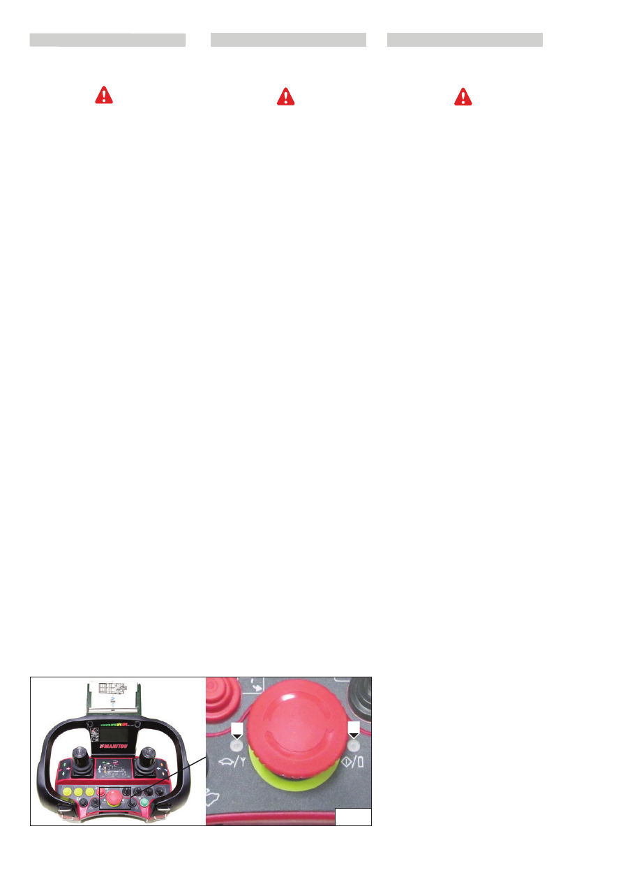
- MICRO LED; to the LH of the stop button 1 (Fig. H10/1)

- LED ON; to the RH of the stop button 2 (Fig. H10/1)

- SOUND; by means of internal warning sound

Indications of the operating status

The pushbutton panel uses the LED ON and MICRO LED to
indicate the current operating status and alarms.

Red LED ON;

the pushbutton panel is active and is

transmitting data to the central unit via radio.

Red LED which flashes once every second;

the battery

is running out.
This indication is preceded by three warning sounds
emitted by the internal buzzer.

MICRO green LED which flashes once, twice, thrice,
four or five times every two seconds; 

the percentage

hydraulic movements speed set are active.

H10 - Onderhoud/storingen opsporen aan de

radiobesturing (optioneel)

In geval van problemen in de radioverbinding van de

radiobesturing, kunt u de dealer raadplegen (zorg

ervoor dat u dan alle aanwijzingen die op het plaatje

van de radiobesturing vermeld zijn bij de hand heeft).

De frequenties worden alleen door de fabrikant

toegekend. Als u deze regel niet in acht neemt verliest

u het recht op  garantie.

SIGNALEN VAN HET KNOPPENBORD

De status en de alarmen worden op het knoppenbord
aangegeven door middel van de groene MICRO LED, de
rode ON LED en het ingebouwde geluidssignaal.
- MICRO LED; links van de stopknop 1 

(fig. H10/1)

- ON LED; rechts van de stopknop 2 

(fig. H10/1).

- GELUID; door middel van intern akoestisch signaal

Indicaties van de staat van werking

Het knoppenbord gebruikt de ON LED en de MICRO LED om
de huidige staat van werking en de alarmen aan te geven.

Rode LED aan; 

het knoppenbord is ingeschakeld en zendt

de gegevens via radio naar de centrale eenheid.

Rode LED knippert één keer per seconde

; de batterij is

bijna leeg.
Deze waarschuwing wordt voorafgegaan door drie
geluidssignalen van de interne zoemer. 

Groene MICRO LED knippert  één, twee, drie, vier of
vijf keer om de twee seconden

; de set snelheden van

de hydraulische bewegingen zijn actief.

H10  -

Manutenzione/ricerca guasti sul 

radiocomando  (optional)

In caso di problemi di collegamento radio con il
sistema del radiocomando, è possibile contattare il
concessionario (munendosi prima di tutte le
indicazioni riportate sull’etichetta del radiocomando).
L’attribuzione delle frequenze viene fatta
esclusivamente dal costruttore. Non attenersi a questa
regola farà perdere il diritto alla garanzia.

SEGNALAZIONI DELLA PULSANTIERA

Le indicazioni di stato e di allarme sono segnalate dalla
pulsantiera tramite il LED verde MICRO, il LED rosso ON e
attraverso il segnale acustico incorporato.

- LED MICRO; a sinistra del pulsante d'arresto

(fig. H10/1)

- LED ON; a destra del pulsante d'arresto 

(fig. H10/1).

- SUONO; tramite segnale acustico interno

Indicazioni dello stato operativo

La pulsantiera utilizza il LED ON e il LED MICRO per indicare
lo stato di funzionamento attuale e gli 
allarmi.

LED rosso acceso;

la pulsantiera è attiva e sta 

trasmettendo i dati all'unità centrale via radio.

LED rosso che lampeggia una volta ogni secondo

; la

batteria si sta esaurendo.
Questa indicazione è preceduta da tre segnali acustici
emessi dal buzzer interno.

LED verde MICRO che lampeggia uno, due, tre,
quattro o cinque volte ogni due secondi

; il set di

velocità movimenti idraulici percentuali sono 
attivi.

3-69

IT

EN

NL

648747 IT

-EN-NL (29/08/2013)

Codici di errore

La pulsantiera esegue una verifica sulle proprie parti ad
ogni accensione e in caso riscontri anomalie manifesta un
codice di errore facendo lampeggiare il LED rosso e suonare
il buzzer interno un certo numero di volte, a seconda del
tipo di errore riscontrato.

Nr. lampeggi

Significato

1

Il manipolatore della 1° funzione non è in posizione neutra in fase di avvio della pulsantiera o è difettoso

2

Il manipolatore della 2° funzione non è in posizione neutra in fase di avvio della pulsantiera o è difettoso

3

Il manipolatore della 3° funzione non è in posizione neutra in fase di avvio della pulsantiera o è difettoso

4

Il manipolatore della 4° funzione non è in posizione neutra in fase di avvio della pulsantiera o è difettoso

5

Il manipolatore della 5° funzione non è in posizione neutra in fase di avvio della pulsantiera o è difettoso

6

Il manipolatore della 6° funzione non è in posizione neutra in fase di avvio della pulsantiera o è difettoso

7

Il manipolatore della 7° funzione non è in posizione neutra in fase di avvio della pulsantiera o è difettoso

8

Il manipolatore della 8° funzione non è in posizione neutra in fase di avvio della pulsantiera o è difettoso

13

Arresto di emergenza riscontrato difettoso durante il self-test

Flashes

Meaning

1

The manipulator of the 1st function is not in neutral position in the startup phase of the pushbutton panel or is defective

2

The manipulator of the 2nd function is not in neutral position in the startup phase of the pushbutton panel or is defective

3

The manipulator of the 3rd function is not in neutral position in the startup phase of the pushbutton panel or is defective

4

The manipulator of the 4th function is not in neutral position in the startup phase of the pushbutton panel or is defective

5

The manipulator of the 5th function is not in neutral position in the startup phase of the pushbutton panel or is defective

6

The manipulator of the 6th function is not in neutral position in the startup phase of the pushbutton panel or is defective

7

The manipulator of the 7th function is not in neutral position in the startup phase of the pushbutton panel or is defective

8

The manipulator of the 8th function is not in neutral position in the startup phase of the pushbutton panel or is defective

13

Emergency stop found to be defective during the self-test

Aantal knipperingen

Betekenis

1

De stuurknuppel van de 1ste functie staat niet in de neutrale stand bij het aanzetten van het knoppenbord of is defect

2

De stuurknuppel van de 2de functie staat niet in de neutrale stand bij het aanzetten van het knoppenbord of is defect

3

De stuurknuppel van de 3de functie staat niet in de neutrale stand bij het aanzetten van het knoppenbord of is defect

4

De stuurknuppel van de 4de functie staat niet in de neutrale stand bij het aanzetten van het knoppenbord of is defect

5

De stuurknuppel van de 5de functie staat niet in de neutrale stand bij het aanzetten van het knoppenbord of is defect

6

De stuurknuppel van de 6de functie staat niet in de neutrale stand bij het aanzetten van het knoppenbord of is defect

7

De stuurknuppel van de 7de functie staat niet in de neutrale stand bij het aanzetten van het knoppenbord of is defect

8

De stuurknuppel van de 8ste functie staat niet in de neutrale stand bij het aanzetten van het knoppenbord of is defect

13

Noodknop defect gebleken tijdens de self-test

Error codes

The pushbutton panel carries out a test on its parts every
time it is switched on and if faults are found an error code
is displayed causing the red LED to flash and sound the
internal buzzer a certain number of times, depending on
the type of error

Foutcodes

Het knoppenbord controleert bij iedere inschakeling zijn
eigen onderdelen en als hij storingen aantreft geeft hij een
foutcode door de interne zoemer en de rode LED een
aantal keren te activeren, naar gelang het type fout.

3-70

SEGNALAZIONI DELL'UNITÀ CENTRALE

Le indicazioni di stato e di allarme sono segnalate
dall'unità centrale tramite i due LED situati sul lato sinistro
della centralina (LED DV e LED STATUS) 
1 (fig.H10/2) e attraverso il display interno a sette 
segmenti  2 (fig.H10/2).

Indicazioni dello stato operativo

L'unità centrale utilizza i LED STATUS e DV per indicare lo
stato di funzionamento attuale e gli allarmi.
Un sistema funzionante si comporta come segue:

LED Status acceso rosso

; l'unità centrale è accesa in

modalità standby (in attesa di collegamento con la
pulsantiera).

LED Status acceso verde

; l'unità centrale è accesa in

modalità operativa (collegamento con la pulsantiera
effettuato).

Il LED DV è usato per indicare lo stato dell'uscita di
comando per l'elettrovalvola di sicurezza (DV).

LED DV rosso acceso

; indica che l'uscita DV è attiva.

Codici di errore

In caso di malfunzionamento l'unità centrale indicherà
l'anomalia facendo lampeggiare il LED STATUS in rosso
mentre sul display interno verrà visualizzato "Er"seguito da
quattro caratteri divisi in due blocchi  corrispondenti al
codice d'errore riscontrato.

Esempio di codice d'errore:

"Er"->"15"->"1A" -> "Er"->"15"->"1A" -> "Er"-  

>"15"->"1A"

Se il problema riscontrato è considerato "temporaneo", il
codice d'errore sarà ripetuto tre volte e poi il radiocomando
ritornerà in stand-by, come appena acceso.
Diversamente, se il malfunzionamento è considerato
"bloccante", il display mostrerà il codice d'errore
continuamente fino a quando il radiocomando sarà spento.
Il codice di errore può manifestarsi dopo l'avvio dell'unità
centrale, dopo l'avvio della pulsantiera (abilitazione
modalità operativa) o dopo l'attivazione di un'uscita.

IT

EN

NL

648747 IT

-EN-NL (29/08/2013)

H10/2

2

1

WARNING SIGNALS ON THE CENTRAL UNIT

The indications of the status and alarm are signalled by the
central unit by means of the two LEDs situated on the LH
side of the control unit (DV LED and STATUS LED) 1
(Fig.H10/2) and by means of the internal display with
seven segments 2 (Fig.H10/2).

Indications of the operating status

The central unit uses the STATUS and DV LEDs to indicate
the current operating status and alarms.
An operating system which acts as follows:

Status red LED On;

the central unit is On in standby

mode (awaiting connection with the pushbutton panel).

Status green LED On;

the central unit is On in operating

mode (connection made with the pushbutton panel).

The DV LED is used for indicating the command output
status for safety solenoid valve (DV).

DEV LED red On; 

indicates that the DV output is active.

Error codes

In case of malfunctioning of the central unit the fault is
indicated by causing the STATUS LED to flash in red on the
internal display displaying "Er" followed by four characters
divided in two blocks corresponding to the error code
found.
Example of error code:
"Er"->"15"->"1A" -> "Er"->"15"->"1A" -> "Er"-
>"15"->"1A"

If the problem found is considered as "temporary", the
error code will be repeated three times and then the radio
control will return to stand-by, and is turned ON.
On the other hand, if the malfunctioning is considered as
“blocking”, the display will show the error code
continuously until the radio control switches off.
The error code may appear after the control unit starts up,
after the pushbutton panel is started up (enabling
operating mode) or after activation of an output.

SIGNALEN VAN DE CENTRALE EENHEID

De staat en alarmen worden door de centrale eenheid
aangegeven door middel van de twee LEDDEN aan de
linkerkant van de centrale (DV LED en STATUS LED) 1
(fig.H10/2) en door middel van het interne zeven-
segmenten display 2 (fig.H10/2).

Indicaties van de staat van werking

De centrale eenheid gebruikt de STATUS en DV LEDDEN om
de huidige staat van werking en de alarmen aan te geven.
Een functionerend systeem werkt als volgt:

Status LED rood verlicht

; de centrale eenheid is aan in

stand-by modus (in afwachting van verbinding met het
knoppenbord).

Status LED groen verlicht

; de centrale eenheid is aan in

operationele modus (verbinding met het knoppenbord
verwezenlijkt).

De DV LED wordt gebruikt om de staat van de output voor
het elektromagnetische veiligheidsventiel (DV) aan te
geven.

DV LED rood verlicht

; geeft aan dat de DV output

geactiveerd is.

Foutcodes

In geval van een storing geeft de centrale eenheid dit aan
door het knipperen van de rode STATUS LED terwijl op het
interne display “Er” wordt weergegeven gevolgd door vier
lettertekens verdeeld in twee blokken overeenkomstig de
waargenomen foutcode.
Voorbeeld van foutcode:
“Er”->”15”->”1A” -> “Er”->”15”->”1A” -> “Er”-
>”15”->”1A”

Als het waargenomen probleem als “tijdelijk” beschouwd
wordt, dan wordt de foutcode drie keer herhaald en keert
dan de radiobesturing terug in stand-by, net als direct
nadat hij is aangezet.
Anders, als de storing als “blokkerend” beschouwd wordt,
dan toont het display de foutcode continu totdat de
radiobesturing wordt uitgezet.
De foutcode kan optreden na de centrale eenheid aangezet
te hebben, na het knoppenbord aangezet te hebben
(activering van de werkmodaliteit) of na de activering van
een output.

3-71

Codici di errore

IT

EN

NL

648747 IT

-EN-NL (29/08/2013)

Indicazione

Significato

Blocco 1                  Blocco 2

01.                              01-07

Errore di checksum (il blocco 2 indica il tipo)

02.                              02

Corto circuito su uscita DV

04.                              01-14

Corto circuito su uscita digitale (il blocco 2 indica quale uscita)

15.                              1A-8B

Errore su uscita analogica (il blocco 2 indica quale uscita)

16.                              1A-8B

Corto circuito su uscita analogica (il blocco 2 indica quale uscita)

17.                              1A-8B

Interruzione su uscita analogica (il blocco 2 indica quale uscita)

17.                               01

Tensione di alimentazione troppo bassa

17.                               02

Tensione di alimentazione troppo alta

Indication

Meaning

Block 1                       Bloc k2

01.                              01-07

Checksum error (block 2 indicates the type)

02.                              02

Short circuit on DV output

04.                              01-14

Short circuit on digital output (block 2 indicates the output)

15.                              1A-8B

Error on analog output (block 2 indicates the output)

16.                              1A-8B

Short circuit on analog output (block 2 indicates the output)

17.                              1A-8B

Interruption on analog output (block 2 indicates the output)

17.                               01

Supply voltage too low

17.                               02

Supply voltage too high

Indicatie

Betekenis

Blok  1                    Blok  2

01.                              01-07

Checksum fout (blok 2 geeft aan welk soort)

02.                              02

Kortsluiting op DV output

04.                              01-14

Kortsluiting op digitale output (blok 2 geeft aan welke output)

15.                              1A-8B

Fout op analoge output (blok 2 geeft aan welke output)

16.                              1A-8B

Kortsluiting op analoge output (blok 2 geeft aan welke output)

17.                              1A-8B

Onderbreking op analoge output (blok 2 geeft aan welke output)

17.                               01

Te lage voedingsspanning

17.                               02

Te hoge voedingsspanning

Error codes

Foutcodes

3-72

Sistema non funzionante

Controllare sempre quanto segue:
• E' presente la tensione di alimentazione del sistema, 

max. 5% Vpicco-picco?
Effettuare la misura sul pulsante di emergenza della gru 
(premuto e rilasciato).

• Il sistema funziona utilizzando il cavo seriale?
• Il sistema funziona in modalità manuale, cioè con il 

selettore in modalità MANUAL?

• Commutare l'interruttore di accensione in REMOTE e 

controllare lo stato dei LEDs e del display interno 
dell'unità centrale.

• Attivare la pulsantiera e controllare lo stato dei LEDs e la 

presenza di eventuali suoni indicanti malfunzionamenti.

• Attivare le funzioni una alla volta e controllare in che

modo i LED si accendono sull'unità centrale e/o sulla 
pulsantiera.

H11 - Riscaldamento

MRT 1840 EASY 360°

IT

EN

NL

648747 IT

-EN-NL (29/08/2013)

System not working

Always check the following:
• System power supply voltage is present, max. 5% Vpeak-
peak?
• Carry out the measurement on the crane emergency
button (pressed and released).
• The system works using serial cable?
• The system works in manual mode, i.e. with the selector in
MANUAL mode?
• Turn the switch on in REMOTE and check the state of the
LEDs and internal display of the central unit.

Activate the pushbutton panel and check the state of the
LEDs and the presence of sounds, if any, indicating
malfunctioning.
• Activate the functions one at a time and check in which
mode the LEDs light up on the central unit and/or on the
pushbutton panel.

H11 - Heating

MRT 1840 EASY 360°

Als het systeem niet werkt

Controleer dan altijd het volgende:
• Is er voedingsspanning, max. 5% Vpiek-piek?
• Voer de meting uit op de noodknop van de kraan
(ingedrukt en losgelaten).
• Werkt het systeem met de seriële kabel?
• Werkt het systeem in de handmatige modus, d.w.z. met
de keuzeschakelaar in de modaliteit MANUAL?
• Zet de aan-schakelaar op REMOTE en controleer de staat
van de LEDDEN en van het interne display van de centrale
eenheid.
• Activeer het knoppenbord en controleer de staat van de
LEDDEN en de aanwezigheid van eventuele geluidsignalen
die storingen aangeven.
• Activeer de functies één voor één en controleer hoe de
LEDDEN op de centrale eenheid en/of op het knoppenbord
gaan branden.

H11 – Verwarming

MRT 1840 EASY 360°

DATI TECNICI - TECHNICAL DATA - TECHNISCHE GEGEVENS

FLUIDO DI RISCALDAMENTO - HEATING 
FLUID - VERWARMINGSVLOEISTOF

RISCALDATORE - HEATING -
VERWARMER

ARIA - AIR - LUCHT

AIRTRONIC 

D2

AIRTRONIC 

D4 (option)

POTENZA TERMICA - THERMIC POWER -
THERMISCH VERMOGEN

(power)

WATT

d

100

d

100

12 o 24 Volt

-40° C / +70° C

-40° C / +85° C

(min)

WATT

Kg/h

2200

105

87

60

42

34

23

12

8

40

24

13

7

185

150

110

65

1800

1200

850

4000

3000

2000

1000

PORTATA ARIA DI RISCALDAMENTO - 
HOT AIR TROUGHPUT -           
DEBIET VERWARMINGSLUCHT

l/h

0,28

0,23

0,15

0,10

0,51

0,38

0,25

0,13

CONSUMO COMBUSTIBILE - 
FUEL CONSUMPTION -           
BRANDSTOFVERBRUIK  

COMBUSTIBILE
FUEL  
BRANDSTOF

gasolio - commerciale (secondo DIN EN 590) 

diesel oil - they trades (in accordance with DIN EN 590) 

 diesel - commercieel (volgens DIN EN 590)

ASSORBIMENTO ELETTRICO - ELECTRIC 
POWER CONSUPTION - ELEKTRISCHE

ELEKTRISCHE STROOMOPNAME

TENSIONE NOMINALE - OPERATING 
RANGE - 

NOMINALE SPANNING

TEMPERATURA AMMESSA       in magazzino
TEMPERATURE                      not in operating

TOEGESTANE TEMPERATUUR   in het magazijn

TEMPERATURA AMMESSA         in esercizio
TEMPERATURE                           in operating

TOEGESTANE TEMPERATUUR tijdens het bedrijf

(min)

(power)

(min)

(min)

(max)

(max)

(max)

(max)

(medium)

(medium)

(medium)

(medium)

WATT

(min)

WATT

Kg/h

l/h

(min)

(min)

(min)

(max)

(max)

(max)

(max)

(medium)

(medium)

(medium)

(medium)

(12-24 Volt)

ALL' AVVIAMENTO - AT START - 

BIJ HET STARTEN

(12-24 Volt)

Tutti i dati hanno una tolleranza di +/- 10% - All the data have one tolerance of  +/- 10% - 

Alle gegevens hebben een tolerantie van +/- 10

(power)

(power)

(power)

(power)

(power)

(power)

3-73

IT

EN

NL

648747 IT

-EN-NL (29/08/2013)

Please also bear the following matters in
mind

The heater must never be allowed to
operate in a closed room (such as a
garage). It must always be turned off when
the truck is refueled.
It is forbidden to operate the heater in
places that may contain inflammable
vapor or dust (such as warehouses where
fuels, coal, sawdust, grain or similar
products are stored). The hot air issued by
the heater must not be allowed to hit
aerosols or gas bottles.
If the heater or system break down,
contact an authorized workshop and make
sure that the repairs are carried out using
genuine spare parts. Repairs carried out
on your own or using spurious spare parts
may be dangerous and are not authorized.
They also void the warranty and, in
Germany, the circulation permit of the
vehicle.

In the case of prolonged inactivity, and

therefore as soon as the period of use of

the heating system is completed, empty the

heater fuel tank completely and wash it out,

and fully drain the metering pump and the

fuel pipe circuit.

Noise level

The maximum noise level threshold is less
than 56 dB (A), measured with the heater
operating in the "medium 1200 Watt"
stage, according to the 3a German
Directive concerning Machine Safety
(GSGV) or DIN 45 635 -part I.

Safety notes

An operating test must be conducted with
the heater prior to the heating period. If
you note an excessive amount of smoke,
unusual combustion noises or a strong
odour of fuel, turn off the heater and
make it unserviceable by taking out the
fuse. In this case, the heater must only be
used after it has been checked by a
competent technician. No liability is
accepted for appliances for which these
safety regulations have not been
observed. Moreover, MANITOU shall not be
responsible for appliances for which the
indications in the operating instructions
have not been observed, which have been
repaired by incompetent persons or for
which genuine spare parts have not been
used.

Er wordt verzocht rekening te houden
met het volgende

De verwarming mag niet aangezet worden
in gesloten ruimtes (bijv. garage) en moet
tijdens het brandstof tanken altijd
uitgeschakeld zijn.
De werking ervan is verboden in ruimtes
waar brandbare dampen of stof aanwezig
kunnen zijn (bijv. opslagplaatsen voor
brandstof, koolstof, zaagsel, graan of iets
dergelijks). Er moet vermeden worden dat
de warme lucht van de verwarming
spuitbussen en gasflessen raakt.
Als er een storing optreedt in de
verwarming of de installatie, moet u zich
wenden tot een bevoegde werkplaats waar
de storing met gebruik van originele
onderdelen gerepareerd wordt.
Eigenhandige reparaties of reparaties met
niet-originele onderdelen kunnen
gevaarlijk zijn en zijn dus niet toegestaan.
Hierdoor vervalt de garantie en, in
Duitsland, de toestemming om met het
voertuig te rijden.
In geval van een lange periode dat de
verwarming niet gebruikt wordt, d.w.z.
gelijk nadat de gebruiksperiode afgelopen
is, de brandstoftank van de verwarming
helemaal legen en schoonmaken, de
doseerpomp en de brandstofleidingen
helemaal legen.

Geluidsemissie

De maximale geluidslimiet is onder de 56
dB (A), gemeten met de verwarming aan
op “medium 1200 Watt”, volgens de 3de
Duitse richtlijn (GSGV) of DIN 45 635 -deel
I.

Veiligheidsvoorschriften

Voor de verwarmingsperiode moet er een
werkingstest uitgevoerd worden met de
verwarming. Als er te veel en langdurig
rook gevormd wordt, of abnormale
verbrandingsgeluiden of een sterke
brandstofgeur, zet dan de verwarming uit
en stel hem buiten bedrijf door de
zekering te verwijderen. In dit geval mag
de verwarming pas weer gebruikt worden
nadat hij door bevoegd personeel
nagekeken is.
Het bedrijf kan niet aansprakelijk gesteld
worden voor apparaten waarvoor deze
veiligheidsvoorschriften niet
in acht genomen zijn. Het bedrijf MANITOU
kan tevens niet aansprakelijk gesteld
worden voor apparaten waarvoor hetgeen
in de gebruiksaanwijzing voorgeschreven
is niet in acht genomen is of waarop niet
professionele reparaties verricht zijn of
met niet originele reserveonderdelen.

Si prega inoltre di tenere presente
quanto segue

Il riscaldatore non deve essere messo in
funzione in luoghi chiusi (ad es. garage), e
deve essere sempre spento durante il
rifornimento di combustibile.
Ne è vietato il funzionamento in locali
dove possono essere presenti vapori o 
polveri infiammabili (es. magazzini di
combustibili, di carbone, di segatura, di
cereali o simili). Bisogna evitare che l'aria
calda del riscaldatore lambisca 
bombolette spray e contenitori di gas.
In caso di guasto del riscaldatore o 
dell'impianto, si raccomanda di rivolgersi
ad una officina autorizzata che ripari il
guasto usando ricambi originali.
Riparazioni fatte da sé o usando ricambi
non originali possono essere pericolose e
non sono quindi autorizzate, fanno inoltre
decadere la garanzia e, in Germania, il
permesso di circolazione del veicolo.

In caso di inattività prolungata e cioè non

appena terminato il periodo di utilizzo,

svuotare completamente e lavare  il 

serbatoio carburante riscaldatore,

scaricare completamente la pompa

dosatrice e il circuito tubazioni combustibile.

Emissione di rumore

La soglia di rumore massima è inferiore a
56 dB (A), misurata con riscaldatore in
esercizio allo stadio “medium 1200 Watt”,
secondo la 3a direttiva tedesca sulla
sicurezza dei macchinari (GSGV) o DIN 45
635 -parte I.

Note sulla sicurezza

Prima del periodo di riscaldamento è
necessario eseguire una prova di 
funzionamento con il riscaldatore. In caso
di formazione eccessiva e prolungata di
fumo, o di rumori di combustione non
usuali o di forte odore di combustibile,
spegnere il riscaldatore e metterlo fuori
servizio togliendo il fusibile. In questo
caso, il funzionamento sarà possibile 
soltanto dopo aver fatto controllare il
riscaldatore da personale competente.
Non si risponde di apparecchi per i quali le
presenti norme di sicurezza non siano
state rispettate. La ditta MANITOU non
risponde inoltre di apparecchi per i quali
non sia stato osservato quanto prescritto
nelle istruzioni per l'uso o siano state 
effettuate riparazioni non professionali o
non utilizzando parti di ricambio originali.

3-74

IT

EN

NL

648747 IT

-EN-NL (29/08/2013)

ELECTRICS DIAGRAM 

AIRTRONIC

D2 /

AIRTRONIC

D4 (OPTION)

Parts list

ELEKTRISCH SCHEMA AIRTRONIC D2 /
AIRTRONIC D4 (OPTION)

SCHEMA ELETTRICO 

AIRTRONIC

D2 /

AIRTRONIC

D4 (OPTION)

3-75

IT

EN

NL

648747 IT

-EN-NL (29/08/2013)

WIRING DIAGRAM KEY

List of components

1.1 Burner 

engine

1.2 Spark 

plug

1.5

Heating sensor and 
flame sensor 

2.1

Control unit

2.2 

Fuel dosing pump

2.7 

12 Volt: 20A; 24 
Volt: 10A Main fuse

2.7.1

5A activation fuse

5.1

Battery

CONTROL ELEMENTS WIRING DIAGRAM
KEY 

List of components

3.1.11 

Round control device

3.2.12 Mini-timer 

(optional)

Colour of wires in diagram

sw black
ws

white

rt

red

ge  

yellow

gn

green

vi  

violet

br

brown

gr  

grey

bl

blue

li   

lilac

Isolate the wires that are not used.

The various connectors are shown from
the wire input side.

LEGENDA ELEKTRISCH SCHEMA

Lijst met onderdelen

1.1

Brandermotor

1.2

Bougie

1.5

Oververhittings- en vlamsensor

2.1

Bedieningscentrale

2.2

Brandstofdoseerpomp

2.7

Hoofdzekering 
12 Volt: 20A; 24 Volt: 10A

2.7.1

Zekering bediening 5A

5.1

Accu

LEGENDA ELEKTRISCH SCHEMA
BEDIENINGSELEMENTEN

Lijst met onderdelen

3.1.11 Rond bedieningselement
3.2.12 Minitimer (optioneel)

Kleuren van de kabels in de schema's 

sw zwart
ws wit 
rt rood 
ge geel 
gn groen 
vi paars
br bruin 
gr grijs
bl lichtblauw 
li lila

Isoleer de niet gebruikte kabels

De verschillende stekkers zijn afgebeeld
vanaf de kant van de ingang van de
kabels

LEGENDA SCHEMA ELETTRICO

Elenco componenti

1.1 Motore 

bruciatore

1.2 Candela
1.5

Sensore di surriscaldamento e 

sensore fiamma

2.1

Centralina di comando

2.2 

Pompa dosatrice combustibile

2.7 Fusibile 

principale

12 Volt: 20A; 24 Volt: 10A

2.7.1

Fusibile azionamento 5A

5.1

Batteria

LEGENDA SCHEMA ELETTRICO 
ELEMENTI DI COMANDO

Elenco componenti

3.1.11  Dispositivo di comando rotondo
3.2.12 Mini-timer 

(opzionale)

Colore dei cavi degli schemi

sw nero
ws bianco
rt

rosso

ge   giallo
gn verde
vi   viola
br

marrone

gr   grigio
bl

azzurro

li    lilla

Isolare i cavi non utilizzati.

I vari connettori sono raffigurati dal lato 
ingresso cavi.


Content      ..     23      24      25      26     ..