Manitou MRT 1440 ST3B (400°), MRT 1640 ST3B (400°), MRT 1840 ST3B (400°-360°). MANUALE D’ISTRUZIONI - 26
 

  Index      Manuals     Manitou MRT 1440 ST3B (400°), MRT 1640 ST3B (400°), MRT 1840 ST3B (400°-360°). MANUALE D’ISTRUZIONI


Search            copyright infringement  


Content      ..     24      25      26      27     ..


Manitou MRT 1440 ST3B (400°), MRT 1640 ST3B (400°), MRT 1840 ST3B (400°-360°). MANUALE D’ISTRUZIONI - 26


3-76

IT

EN

NL

648747 IT

-EN-NL (29/08/2013)

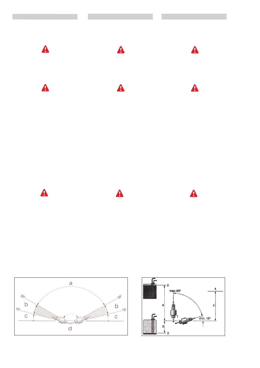
Dosing pump assembly positions 

Always position the dosing pump with the
delivery side upwards.

Respect the minimum inclination of 15°!

Any assembly position exceeding a
minimum inclination of 15° is allowed, but
inclinations between 15° and 35° are
preferable.

The fuel piping between the dosing pump

and heater must possibly be from below

upwards.

Fig. A:
a

permitted inclination

b

preferable

c

not permitted

dosing pump

Permitted pressure head Fig. B:

Difference in level between vehicle tank
and dosing pump:
a = max. 3 m
Difference in level for non-pressurized
tanks:
b = max. 1 m - for intake tube internal 

Ø  2 mm

b = max. 1,5 m - for intake tube internal 

Ø 5 mm

Check to make sure the tank vent is clear.

Difference in level in case of tank in which
a depression is formed at the intake (0.03
bar valve on tank plug):
b = max. 0.4 m
Difference in level between dosing pump
and heater:
c = max. 2 m

Montageposities van de doseerpomp

De doseerpomp altijd met de perszijde
naar boven plaatsen.

Minimaal 15°!

Alle montageposities met een inclinatie
van meer dan 15° zijn toegestaan, maar
inclinaties tussen de 15° en 35° zijn te
verkiezen.

De brandstofleidingen tussen de

doseerpomp en de verwarming moeten

mogelijkerwijs van beneden naar boven

lopen.

Fig. A:

a toegestane inclinaties 
b bij voorkeur
c niet toegestaan
d doseerpomp

Toegestane opvoerhoogte’s Fig. B:

Hoogteverschil tussen de tank van het
voertuig en de doseerpomp:
a = max. 3 m
Hoogteverschil voor niet onder druk
staande tanks:
b = max. 1 m - voor aanzuigleiding met
binnendiameter 2 mm
b = max. 1,5 m - voor aanzuigleiding
met binnendiameter 5 mm

Controleren of de ontluchting van de tank

vrij is.

Hoogteverschil in een tank waarin bij de
aanzuiging onderdruk gevormd wordt
(ventiel van 0,03 bar op de tankdop): 
b = max. 0,4 m
Hoogteverschil tussen doseerpomp en
verwarming:
c = max. 2 m

Posizioni di montaggio della pompa
dosatrice

Posizionare la pompa dosatrice sempre con il
lato mandata verso l’alto.

Rispettare l’inclinazione minima di 15°!

É consentita qualsiasi posizione di montaggio
con un inclinazione superiore ai 15°, ma
sono preferibili inclinazioni comprese tra 15°
e 35°.

Le tubazioni combustibile tra pompa

dosatrice e riscaldatore devono avere

possibilmente un andamento dal basso verso

l’alto.

Fig. A:

inclinazioni ammesse

b  

preferibili

c  

non ammesse

d  

pompa dosatrice

Prevalenze ammesse Fig. B:

Dislivello tra serbatoio del veicolo e pompa
dosatrice:
a = max. 3 m
Dislivello per serbatoi non pressurizzati:
b = max. 1 m - per tubo di aspirazione Ø 

interno 2 mm

b = max. 1,5 m - per tubo di aspirazione 

Ø interno 5 mm

Controllare che lo sfiato del serbatoio sia

libero.

Dislivello in caso di serbatoio in cui
all’aspirazione si forma depressione
(valvola da 0,03 bar sul tappo serbatoio):
b = max. 0,4 m
Dislivello tra pompa dosatrice e riscaldatore:
c = max. 2 m

3-77

IT

EN

NL

648747 IT

-EN-NL (29/08/2013)

Operation 

Switching on

When the heater is switched on, the
indicator light on the control device lights
up. The spark plug lights up and the
engine starts running at low speed.

If there is too much residual heat from a
previous combustion in the heat
exchanger, only the engine will run initially
(cooling phase). When the residual heat
has been removed, the startup process
begins.

Startup

AIRTRONIC 

D2 

After about 60 seconds the fuel supply
begins and the fuel-air mixture in the
combustion chamber is ignited. After
about 60 seconds following recognition of
the flame by the combined sensor (flame
sensor), the spark plug switches off. After
another 120 seconds  the AIRTRONIC
reaches the "POWER" level (maximum
quantity of fuel and maximum engine
speed).

AIRTRONIC

D4 (option)

After about 60 seconds the fuel supply
begins and the fuel-air mixture in the
combustion chamber is ignited. After
about 80 seconds following recognition of
the flame by the combined sensor (flame
sensor), the spark plug switches off and
the AIRTRONIC functions in the regulation
phase.

Selecting temperature by means of
control device

The regulation knob is used to set the
required internal temperature; the
temperature may vary between +10°C
and +30°C depending on the type of
heater, the size of the compartment that
requires heating and the outside
temperature.
Setting the temperature using the knob is
usually based on the operator's
experience.

Beschrijving van de werking

Inschakelen

Bij het inschakelen van de verwarming licht
het controlelampje op het bedieningspaneel
op. De bougie wordt ingeschakeld en de
motor start met laag toerental.

Is door een vorige bedrijfstoestand nog te
veel restwarmte aanwezig in de
warmtewisselaar, dan werkt eerst alleen
de motor (afkoelfase). Als de restwarmte
afgevoerd is, begint de startprocedure.

Start

AIRTRONIC 

D2

Na ongeveer 60 sec. start de
brandstoftoevoer en zal het brandstof-
luchtmengsel in de verbrandingskamer
ontsteken. Nadat de combisensor
(vlamvoeler) de vlam herkend heeft, wordt
na ongeveer 60 sec. de bougie
uitgeschakeld. Na nog 120 seconden
bereikt de AIRTRONIC de stand “POWER“
(maximale brandstofhoeveelheid en
maximaal motortoerental).

AIRTRONIC 

D4 (optie)

Na ongeveer 60 sec. start de
brandstoftoevoer en zal het brandstof-
luchtmengsel in de verbrandingskamer
ontsteken. Nadat de combisensor
(vlamvoeler) de vlam herkend heeft, wordt
na ongeveer 80 sec. de bougie
uitgeschakeld en werkt de AIRTRONIC in
de regelfase.

Temperatuurinstelling met het
bedieningselement

Met de knop wordt de gewenste
ruimtetemperatuur ingesteld; deze kan,
afhankelijk van het type verwarming, van
de afmetingen van de te verwarmen
ruimte en van de buitentemperatuur
variëren van +10°C tot +30° C.
Baseer u op uw eigen ervaring om de
temperatuur met de knop in te stellen.

Descrizione del funzionamento 

Accensione

All'accensione del riscaldatore, la spia di
controllo sul dispositivo di comando si
illumina. Viene accesa la candela e il
motore si avvia a basso numero di giri.

Se nello scambiatore di calore è presente
troppo calore residuo di una precedente
combustione, inizialmente funziona
soltanto il motore (fase di
raffreddamento). Quando il calore residuo
è stato asportato, inizia il processo di
avviamento.

Avviamento

AIRTRONIC

D2

Dopo circa 60 secondi inizia
l'alimentazione del combustibile e si
accende la miscela combustibile-aria nella
camera di combustione. Dopo circa 60
secondi dal riconoscimento della fiamma
da parte del sensore combinato (sensore
di fiamma), la candela si spegne. Dopo
ulteriori 120 secondi l'AIRTRONIC
raggiunge il livello "POWER" (massima
quantità di combustibile e massimo
regime del motore).

AIRTRONIC

D4 (option)

Dopo circa 60 secondi inizia
l'alimentazione del combustibile e si
accende la miscela combustibile-aria nella
camera dì combustione. Dopo circa 80
secondi dal riconoscimento della fiamma
da parte del sensore combinato (sensore
di fiamma), la candela si spegne e
l'AIRTRONIC funziona nella fase di
regolazione.

Selezione della temperatura mediante il
dispositivo di comando

La manopola di regolazione serve a
impostare la temperatura interna
desiderata; la temperatura può variare tra
+10°C e +30°C a seconda del tipo di
riscaldatore, delle dimensioni del vano da
riscaldare e della temperatura esterna.
Per impostare la temperatura con la
manopola, basarsi sulla propria esperienza.

3-78

IT

EN

NL

648747 IT

-EN-NL (29/08/2013)

Regulation during operation

During operation, the atmospheric
temperature and the temperature of the
air taken in are constantly measured. If
the temperature measured is higher than
that set on the control element, the
regulation system intervenes.
There are four regulation stages, to allow
dosing of the heat from the AIRTRONIC
precisely according to requirements. The
engine rpm and fuel quantity correspond
to the relative regulation stage. If the
temperature set is exceeded even at the
"minimum" speed, the AIRTRONIC passes
to the regulation phase and is turned to
"OFF". A wash lasting about 4 minutes
follows to cool the heater.
Successively the engine continues to run
at minimum until the new ignition (in case
of new air circulation) or switches off (if
external air is taken in).

Ventilation method

To use the heater in ventilation mode,
activate the "heater/ventilation" switch
before switching the AIRTRONIC on.

Switching off

When the AIRTRONIC is switched off, the
control indicator light goes out and fuel
supply is shut off. A wash lasting about 4
minutes follows to cool the heater.
During the wash, the spark plug is
switched on for 40 seconds to eliminate
combustion residues. Special case:
If at the time of switching off there is no
fuel supply or the AIRTRONIC is in "OFF"
regulation, the heater switches off without
the wash.

~Heating at special altitudes. 
- up to 1500 m: 

unlimited operation 

- beyond 1500 m:

in case of short stays (crossing a pass,

brief halt) heater operation is generally
possible.

In case of long halts (for example, winter
camps) the fuel must be adapted to the
altitude. Please contact the area
representative.

The client must be provided with the user
instructions enclosed with the control
elements.

Regeling tijdens het bedrijf

Tijdens het bedrijf worden de temperatuur
van de ruimte en de temperatuur van de
aangezogen lucht continu gemeten. Wordt
deze opgemeten temperatuur hoger als
die met het bedieningselement is
ingesteld, dan treedt het regelsysteem in
werking.
De verwarming heeft 4 verschillende
regelstanden, zodat een fijne aanpassing
van de door de AIRTRONIC geleverde
warmte aan de warmtebehoefte mogelijk
is. Het motortoerental en de
brandstofhoeveelheid komen overeen met
de desbetreffende regelstand. Als zelfs in
de “minimum” regelstand de ingestelde
temperatuur overschreden wordt, gaat de
AIRTRONIC over op de “regelfase” en
wordt op “UIT” gezet. Daarop volgen
ongeveer 4 minuten reinigen voor het
afkoelen van de verwarming. Daarna loopt
de motor met een laag toerental door tot
aan een nieuwe start (in geval van
luchtcirculatie) of gaat uit (in geval van
aanzuiging van buitenlucht).

Ventilatiemodus

Om de verwarming in de ventilatiemodus
te gebruiken, de schakelaar
“verwarming/ventilatie” activeren voor de
AIRTRONIC aan te zetten.

Uitschakelen

Bij het uitschakelen van de AIRTRONIC
gaat het controlelampje uit en wordt de
brandstoftoevoer verbroken. Voor de
afkoeling van het apparaat volgt een
reiniging van ongeveer 4 minuten.
Tijdens de reiniging, wordt de bougie
gedurende 40 seconden ingeschakeld om
de verbrandingsresten te verwijderen:
Speciaal geval:
Als de brandstoftoevoer op het moment
van uitschakelen nog niet plaatsgevonden
heeft of de AIRTRONIC zich in de regeling
“UIT“ bevindt, gaat de AIRTRONIC zonder
reiniging uit.

~Verwarming op bijzondere hoogte.
- tot 1500 m:
onbeperkte werking
- boven de 1500 m:
in geval van een kort verblijf (door een
bergpas rijden, korte pauze) is de werking
van de verwarming in grote lijnen mogelijk.

Bij een langer verblijf (bijv. ‘s winters
kamperen) moet de brandstof aan de
hoogte worden aangepast. Gelieve contact
op te nemen met de plaatselijke
vertegenwoodiger.

De met de bedieningselementen
meegeleverde gebruiksaanwijzing moet
aan de klant overhandigd worden.

Regolazione durante il funzionamento

Durante il funzionamento la temperatura
ambiente e la temperatura dell'aria
aspirata vengono costantemente misurate.
Se la temperatura rilevata è superiore a
quella impostata sull'elemento di
comando, interviene il sistema di
regolazione.
Sono previsti 4 stadi di regolazione, per
consentire di dosare in modo preciso il
calore dell'AIRTRONIC a seconda del
fabbisogno. II numero di giri del motore e
la quantità di combustibile corrispondono
al rispettivo stadio di regolazione. Se la
temperatura impostata dovesse essere
superata anche al regime "minimo",
l'AIRTRONIC passa alla fase di regolazione
e viene commutato su "SPENTO" . Segue
un lavaggio di circa 4 minuti per il
raffreddamento del riscaldatore.
Successivamente il motore continua a
funzionare al minimo fino ad una nuova
accensione (nel caso di ricircolo aria) o si
spegne (nel caso di aspirazione di aria
esterna).

Modalità di ventilazione

Per utilizzare il riscaldatore in modalità di
ventilazione, azionare il commutatore
"riscaldamento/ventilazione" prima di
accendere l'AIRTRONIC.

Spegnimento

Spegnendo l'AIRTRONIC, la spia di
controllo si spegne e viene interrotta
l'alimentazione del combustibile. Segue un
lavaggio di circa 4 minuti per il
raffreddameñto del riscaldatore.
Durante il lavaggio, la candela viene
accesa per 40 secondi per eliminare i
residui della combustione. Caso
particolare:
Se al momento dello spegnimento non era
ancora avvenuta l'alimentazione
combustibile o se l'AIRTRONIC si trova in
regolazione "SPENTO", il riscaldatore si
spegne senza lavaggio.

~Riscaldamento ad altitudini particolari . 
- fino a 1500 m: 

funzionamento illimitato 

- oltre 1500 m:

in caso di permanenza breve (attraver  
samento di un passo, breve sosta) in 
linea di massima il funzionamento del 
riscaldatore è possibile.

In caso di sosta prolungata (p. es.
campeggio invernale) è necessario
adattare il combustibile all'altitudine. Si
prega di contattare il rappresentante di
zona.

Consegnare al cliente le istruzioni per l'uso
allegate agli elementi di comando.

3-79

IT

EN

NL

648747 IT

-EN-NL (29/08/2013)

Controls and safety devices

If the AIRTRONIC does not switch on within
90 seconds following the start of the fuel
supply, the switching operation is
automatically repeated.
If the second switching on also does not
occur within 90 seconds following start of
the fuel supply, the heater switches off
due to a fault condition, the fuel supply is
shut off and there is an approx. 4-minute
wash.

• If the flame goes out during operation,
try a new ignition.
If the AIRTRONIC does not switch on within
90 seconds starting from the beginning of
the fuel supply or it switches on and then
switches off within 15 minutes, the heater
switches itself off due to a fault condition,
the fuel supply is shut off and there is a 4-
minute wash. Switching off due to a fault
condition can be cancelled by switching
the heater off and then on immediately.
Do not switch the heater off and on
consecutively more than twice!

•In case of overheating, the
flame/overheating sensor is activated, fuel
supply is shut off and the heater switches
off due to a fault condition. After
eliminating the cause of the superheating,
startup the AIRTRONIC again by switching
it off and then on.

•If the minimum and maximum voltage
limits are exceeded, after 20 seconds, the
heater switches off due to a fault
condition.

•The AIRTRONIC does not switch on if the
spark plug or engine is defective, 
or if the electric connection to the dosing
pump is cut off.

•In case of detective flame/overheating
sensor, or interrupted electric connection,
the AIRTRONIC switches on, and only
during the startup phase it switches off
due to a fault condition.

• The engine rpm is checked constantly. 

If the engine does not start up or if the
rpm differs by more than 10% of the rated
value, after 30 seconds the heater
switches itself off due to a fault condition.
After the AIRTRONIC is switched off, the
spark plug is switched on for 40 seconds
during the wash to eliminate combustion
residue.

Besturings- en veiligheidsvoorzieningen

Ontsteekt de AIRTRONIC binnen 90 sec.
na het begin van de brandstoftoevoer niet,
dan wordt automatisch de startprocedure
herhaald.
Ontsteekt de AIRTRONIC na nogmaals 90
sec. brandstoftoevoer nog niet, dan volgt
er een storingsuitschakeling, met
onderbreking van de brandstoftoevoer en
reiniging van ongeveer 4 minuten.

• Gaat de vlam tijdens het bedrijf uit, dan
wordt automatisch een nieuwe start
geprobeerd.
Ontsteekt de AIRTRONIC binnen 90
seconden na het beginnen van de
brandstoftoevoer niet of ontsteekt de
AIRTRONIC wel, maar gaat binnen 15
minuten weer uit, dan volgt er een
storingsuitschakeling met onderbreking
van de brandstoftoevoer en reiniging van
ongeveer 4 minuten. Door de verwarming
onmiddellijk uit en weer in te schakelen
kan de storingsuitschakeling geannuleerd
worden. De verwarming niet vaker dan 2
maal achtereenvolgens uit- en weer
inschakelen!

• In geval van oververhitting grijpt de
vlam-/oververhittingssensor in, de
brandstoftoevoer wordt onderbroken en er
volgt storingsuitschakeling. Nadat de
oorzaak van de oververhitting is
opgeheven kan de AIRTRONIC door uit- en
weer inschakelen weer gestart worden.

• Als de minimale of maximale
spanningslimiet overschreden wordt, volgt
na 20 seconden storingsuitschakeling.

• Bij defecte bougie of motor of
onderbroken elektrische kabel naar de
doseerpomp start de AIRTRONIC niet.

• Bij defecte vlam-/oververhittingssensor
of onderbroken elektrische kabel start de
AIRTRONIC en pas tijdens de startfase
volgt de storingsuitschakeling.

• Het toerental van de motor wordt
continu gecontroleerd.

Als de motor niet start of als het toerental
meer dan 10% verschilt van de nominale
waarde, volgt na 30 seconden
storingsuitschakeling.
Bij het uitschakelen van de AIRTRONIC
wordt de bougie gedurende 40 sec. tijdens
de reiniging ingeschakeld, om de
verbrandingsresten te verwijderen.

Dispositiví di comando e di sicurezza

Se I’AIRTRONIC non si accende entro 90
secondi dall'inizio dell'inizio
dell'alimentazione combustibile,
l'operazione di accensione viene ripetuta
automaticamente.
Nel caso che anche la seconda
accensione non avvenga entro 90 secondi
dall'inizio dell'alimentazione combustibile,
il riscaldatore si spegne per guasto, con
interruzione dell'alimentazione
combustibile e lavaggio di circa 4 minuti.

• Se durante il funzionamento si dovesse
spegnere la fiamma, viene ritentata una
nuova accensione.
Se I’AIRTRONIC non si accende entro 90
secondi dall'inizio dell'alimentazione
combustibile oppure se si accende per poi
spegnersi nuovamente entro 15 minuti, ìl
riscaldatore si spegne per 
guasto, con interruzione dell'alimentazione
combustibile e lavaggio di circa 4 minuti.
Lo spegnimento per guasto può essere
annullato spegnendo e riaccendendo
istantaneamente il riscaldatore. Non
spegnere e riaccendere il riscaldatore per
più di 2 volte consecutive!

•In caso di surriscaldamento interviene il
sensore di fiamma/surriscaldamento,
l'alimentazione del combustibile viene
interrotta e il riscaldatore si spegne per
guasto. Dopo aver eliminato la causa del
surriscaldamento, riavviare l'AIRTRONIC
spegnendolo e riaccendendolo.

•Se viene superato il limite minimo o
massimo di tensione, dopo 20 secondi il
riscaldatore si spegne per guasto.

•L'AIRTRONIC non si accende se la
candela o il motore sono difettosi, 
oppure se il collegamento elettrico alla
pompa dosatrice è interrotto.

•In caso di sensore di
fiamma/surriscaldamento difettoso o
collegamento elettrico interrotto,
l'AIRTRONICsi accende, e solo durante la
fase di avvio si spegne per guasto.

• II numero di giri del motore viene 
controllato costantemente. 

Se il motore non si avvia o se il numero di
giri del motore differisce di oltre il 10% dal
valore nominale, dopo 30  secondi il
riscaldatore si spegne per guasto.
Allo spegnimento dell'AIRTRONIC, la
candela viene accesa per 40 secondi
durante il lavaggio, per eliminare i 
residui della combustione.

3-80

IT

EN

NL

648747 IT

-EN-NL (29/08/2013)

Procedure to be adopted in case of a fault.
If the AIRTRONIC does not start up when
switched on:

Switch the AIRTRONIC off and then on

again, but never more than twice
consecutively.

If the AIRTRONIC does not still switch on:

Check to see if there is fuel in the tank.

Check the fuses:

AIRTRONIC 12 v - 20 A main fuse 
AIRTRONIC 24 V - 10 A main fuse 
AIRTRONIC 12 / 24 V - 5 A activation fuse 

Check the electric cables, wiring and

fittings.

Check the heating air, combustion air 

and exhaust piping for blockage.
If no fault is found, carry out a diagnostic
test using the Eberspächer diagnostic
equipment or the modular timer, as
indicated in the AIRTRONIC Manual for
Troubleshooting and Instructions for repair.

In case of electric welds on the vehicle,

disconnect the battery positive wire and

connect it to earth, to protect the

electrical/electronic components of the 

AIRTRONIC.

In geval van storingen de volgende procedure
verrichten
Als de AIRTRONIC na inschakelen niet start:

• De AIRTRONIC uit- en weer inschakelen, echter
niet vaker dan 2 maal achter elkaar.

Als de AIRTRONIC dan nog niet start:

• Controleren of er voldoende brandstof in de
tank zit.

• De zekeringen controleren:

AIRTRONIC 12 v - hoofdzekering 20 A AIRTRONIC
24 V - hoofdzekering 10 A AIRTRONIC 12 / 24 V –
zekering activering 5 A

• Elektrische kabels, verbindingen en
aansluitingen controleren.

• Controleren of de verwarmingsluchtkanalen,
verbrandingsluchtkanalen of de uitlaatgasafvoer
niet verstopt zijn.
Zijn deze punten in orde, dan een diagnosetest
met het speciale Eberspächer diagnose-
apparaat of met de moduulklok uitvoeren, zoals
in de handleiding Storingen opsporen en
reparatie-instructies van de AIRTRONIC vermeld
is.

Bij elektrische laswerkzaamheden aan het

voertuig moet ter bescherming van de

elektrische/elektronische onderdelen van de

AIRTRONIC de pluskabel van de accu

losgekoppeld en aan de massa aangesloten

worden.

Procedura da adottare in caso di guasto
Se all'accensione l'AIRTRONIC non si avvia:

• Spegnere e riaccendere l'AIRTRONIC, 

ma non più di 2 volte consecutive.

Se IAIRTRONICnon si accende ancora:

• Controllare se c'è combustibile nel 

serbatoio.

• Controllare i fusibili:

AIRTRONIC 12 v - fusibile principale 20 A 
AIRTRONIC 24 V -fusibile principale 10 A 
AIRTRONIC 12 / 24 V - fusibile 

azionamento 5 A

• Controllare cavi elettrici, collegamenti e
allacciamenti.

• Controllare se sono ostruite le tubazioni
dell'aria di riscaldamento, dell'aria di
combustione o di scarico.
Se non viene rilevata nessuna anomalia,
eseguire un test diagnostico con l'apposito
apparecchio di diagnosi Eberspächer o con
il timer modulare, come indicato nel
manuale Ricerca guasti e istruzioni di
riparazione dell'AIRTRONIC.

In caso di lavori di saldatura elettrica sul

veicolo, si raccomanda di staccare il positivo

dalla batteria e di collegarlo a massa, a

protezione dei componenti

elettrici/elettronici dell'AIRTRONIC.

3-81

IT

EN

NL

648747 IT

-EN-NL (29/08/2013)

Fuel supply

Fuel quality for diesel heaters.
The heater runs smoothly on standard
commercialquality diesel in accordance
with DIN EN 590, whichyou use to run your
vehicle engine.

Fuel for special cases

In special cases (above 0 °C), the heater
can also runon fuel oil EL or paraffin.

Fuel for low temperatures

Refineries and fuel service stations
automaticallyadjust the fuel to normal
winter temperatures (winterdiesel). This
means that difficulties are only to
beexpected for extreme drops in
temperature, as alsoapply to the vehicle
engine. Please also refer to thevehicle
manual.If the heater is run from a
separate tank, pleasecomply with the
following rules:For temperatures above 0
°C, any kind of diesel fuelas per DIN EN
590 can be used.

If no special diesel fuel is available for
low temperatures

, then paraffin or petrol

should be mixed with the fuel according to
the following table:

Please note

Please note

• Mixtures with used oil are not allowed!
•After refuelling with winter or cold diesel 

or the listedblends, the fuel pipes and 
the dosing pump must befilled with the
new fuel by letting the heater run for
15 mins.!

Operation with biodiesel (PME)

AIRTRONICT he heater is not certified for
operation with biodiesel.
Biodiesel can be added to the fuel to up to
10%.

Brandstoftoevoer

De verwarming werkt probleemloos met de
gewoonlijk in de handel beschikbare
dieselolie voor motoren (DIN EN 590).

Brandstof voor bijzondere gevallen

In geval van nood werkt de verwarming ook
op gasolie voor de verwarming (temperaturen
boven de 0°C) of op aardolie.

Brandstof voor lage temperaturen

De raffinaderijen of de tankstations zorgen
ervoor de brandstof aan de
wintertemperaturen aan te passen
(winterdiesel).
Er kunnen zich dus alleen moeilijkheden
voordoen in geval van extreem lage
temperaturen.

Als de verwarming door een aparte tank
gevoed wordt, het volgende in acht nemen:
Voor temperaturen boven de 0°C kunnen alle
soorten dieselolie gebruikt worden die in
overeenstemming zijn met DIN EN 590.

Als er bij zeer lage temperaturen geen
speciale dieselolie beschikbaar is voeg dan
aardolie of benzine toe zoals in de volgende
tabel wordt aangegeven.

WAARSCHUWING
•Het is niet toegestaan gebruikte olie toe te
voegen.
•Na de winterdiesel of de arctische diesel
getankt te hebben of na de aangegeven
brandstoffen toegevoegd te hebben,
controleren of de brandstofleidingen en -
pomp gevuld zijn door de verwarming 15
minuten te laten werken!

Werking met ecologische diesel (biodiesel)

Voor de AIRTRONIC verwarming is het gebruik
van ecologische diesel niet toegestaan. Het
toevoegen van ecologische diesel is
toegestaan tot ongeveer 10%.

Alimentazione combustibile

Il riscaldatore funziona senza problemi con
il gasolio normalmente disponibile in
commercio usato per il motore 
(DIN EN 590).

Combustibile per casi particolari

In caso di necessità il riscaldatore può
funzionareanche con gasolio per 
riscaldamento (temperature superiori a 0
°C) o con petrolio.

Combustibile per basse temperature

Le raffinerie o i distributori di carburante
provvedono ad adeguare il combustibile
alle temperature invernali 
(gasolio invernale).
Possono quindi verificarsi difficoltà solo in
caso di estremi abbassamenti della
temperatura. 

Se il riscaldatore viene alimentato da un
serbatoio separato, attenersi a quanto
segue:
Per temperature superiori a 0 °C può
essere usato qualsiasi tipo di gasolio
conforme a DIN EN 590.

Se, con temperature molto basse

, non

fosse disponibile un gasolio speciale,

aggiungere petrolio o benzina

come indicato nella seguente tabella.

AVVERTENZA

AVVERTENZA

•Non è ammessa l‘aggiunta di olio 

usato.

•Dopo aver fatto rifornimento di gasolio 

invernale o digasolio artico o dopo aver 
aggiunto i combustibiliindicati, 
controlla re il riempimento delle tubazioni
e della pompa del combustibile facendo 
funzionare ilriscaldatore per 15 minuti!

Funzionamento con gasolio
ecologico (biodiesel)

Per il riscaldatore AIRTRONIC 

non

è

ammesso l’uso di gasolio ecologico. 
E’ ammessa l’aggiunta di gasolio
ecologico fino a circa il 10 %.

Temperatura

Temperatura

Gasolio invernale

Gasolio invernale

Aggiunta

Aggiunta

da 0 °C a –25 °C 

100 %

––––

da –25 °C a –40 °C 

50 % * 

50 % di petrolio o benzina

* o 100 % di gasolio speciale per basse temperature (gasolio artico).

Temperature

Temperature

Winter diesel

Winter diesel

Addition

Addition

0 °C  to  –25 

°C100%

––––

25 °C  to  –40 

°C50%

*50% paraffin or petrol

*  or 100% special cold diesel fuel (Arctic diesel).

Temperatuur

Temperatuur

Winterdiesel

Winterdiesel

Toevoeging

Toevoeging

van 0 °C tot –25 °C 100 %

van –25 °C tot –40 °C 

50 % * 

50 % aardolie of benzine

* of 100 % speciale diesel voor lage temperaturen (arctische diesel).

3-82

IT

EN

NL

648747 IT

-EN-NL (29/08/2013)

13

Guarnizioni flangia

14

Camera di combustione

15

Bocchetta di uscita
D2= Ø 60 mm
D4= Ø 75/90 mm

16

Tubo aria di combustione

17

Pompa dosatrice

18

Filtro combustibile montato nella
pompa dosatrice

19

Bocchetta orientabile

20

Tubo di scarico

F  = Aria fresca
W = Aria calda
A  = Gas di scarico
B = Combustibile
V  = Aria di combustione

Disegno in sezione riscaldatore

Elenco componenti

1

Ventilatore aria di riscaldamento

2

Centralina di comando

3

Ventilatore aria di combustione

4

Candela

5

Coperchio

6

Scambiatore di calore

7

Sensore fiamma/Surriscaldamento

8

Timer modulare con potenziometro

9

Commutatore “riscaldamento/
ventilazione

10

Portafusibili con fusibile principale e 
fusibile “azionamento”

11

Motore elettrico

12

Raccordo combustibile

3-83

IT

EN

NL

648747 IT

-EN-NL (29/08/2013)

Cross-section drawing of heater

13

Flange gaskets

14

Combustion chamber

15

Outlet spout
D2= Ø 60 mm
D4= Ø 75/90 mm

16

Combustion air tube

17

Dosing pump

18

Fuel filter mounted in dosing pump

19

Orientable spout

20

Exhaust pipe

F  = Cool air
W = Hot air
A  = Exhaust gas
B = Fuel
V  = Combustion air

List of components

1

Air heater fan

2

Control unit

3

Combustion air fan

4

Spark plug

5

Cover

6

Heat exchanger

7

Flame/overheating sensor 

8

Modular Timer with 

\

potentiometer 

9

"Heating/ventilation" switch

10

Fusebox with main switch and 

"activation" switch
11

Electric engine

12

Fuel connection


Content      ..     24      25      26      27     ..