Manitou MRT 1440 ST3B (400°), MRT 1640 ST3B (400°), MRT 1840 ST3B (400°-360°). MANUALE D’ISTRUZIONI - 23
 

  Index      Manuals     Manitou MRT 1440 ST3B (400°), MRT 1640 ST3B (400°), MRT 1840 ST3B (400°-360°). MANUALE D’ISTRUZIONI


Search            copyright infringement  


Content      ..     21      22      23      24     ..


Manitou MRT 1440 ST3B (400°), MRT 1640 ST3B (400°), MRT 1840 ST3B (400°-360°). MANUALE D’ISTRUZIONI - 23


3-52

IT

EN

NL

648747 IT

-EN-NL (29/08/2013)

IT

EN

NL

1

-EVERY 2000 HOURS OF SERVICE 

OR EVERY 2 YEARS

F1 -

Vidange le liquide de refroidissement

This series of operations must be carried out whenever it is
necessary or at least once every two years before the
winter..
Position the fork lift truck on level ground with the I.C.
engine switched off and cold.

When maintenance or repairs are carried out on the
engine cooling system, the procedure must be carried
out with the engine resting level on the ground. This
makes it possible to check the coolant level accurately.
It is thus also possible to avoid the risk of introducing
an air bubble in the cooling system.

Pressurised system: the boiling coolant can cause
serious burns. Before opening the filler cap, stop the
engine and allow the cooling circuit components to
cool down. Slacken the pressure cap slowly to discharge
pressure.

Recycle or dispose of the used coolant correctly in
conformity with the provisions and the local
regulations.

The I.C. engine does not contain anti-corrosive
elements, and must always be filled with a minimum
mixture, consisting of 25% anti-freeze containing
ethylene glycol.

Liquid drainage

- Open the engine hood.
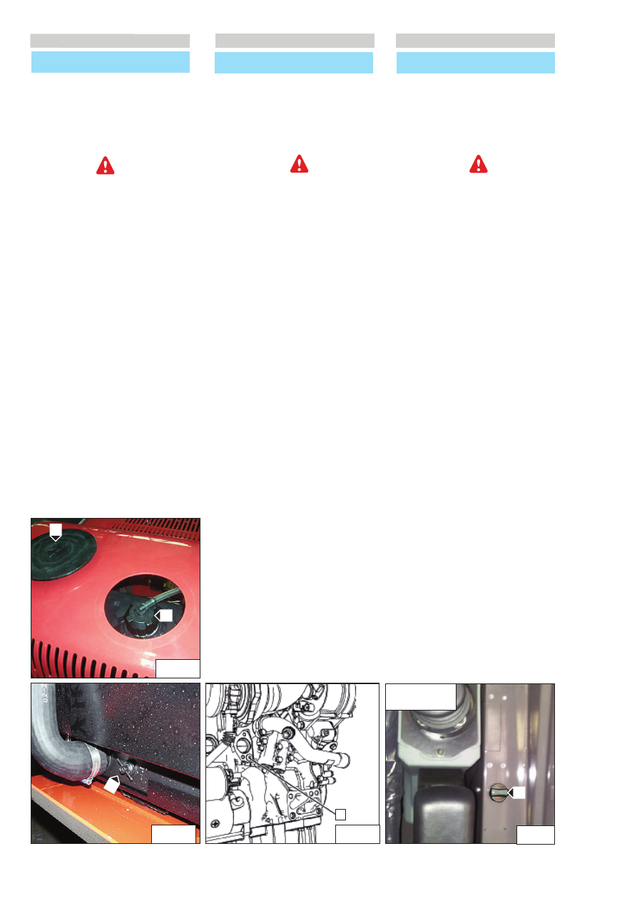
- Remove the access hatch “1” (F1/1).

- Stop the engine and leave it to cool. Slowly slacken the
filler cap to discharge all the pressure. Remove the cap of
the cooling system filler opening “2” (F1/1).
- Switch on the heating to maximum to make drainage “1”
easier (F1/4). (MRT 400°).
- Place a container under the drainage valve “1”(F1/2) of the
radiator and the drainage cap “1” (F1/3) of the engine block
and slacken it.

Drain out the coolant.

OM DE 1000 WERKUREN OF OM DE 2 JAAR

F1 - 

De koelvloeistof van het koelcircuit vervangen

Deze serie handelingen moet wanneer nodig uitgevoerd
worden of minstens eens in de 2 jaar als de winter op komst
is.
De heftruck op een horizontaal stuk grond zetten met de
verbrandingsmotor uit en afgekoeld.

Als u enig onderhoud of reparaties aan het
koelsysteem van de motor verricht, dan moet deze
procedure met de motor gelijk met de grond
gebeuren. Zodoende kunt u het niveau van de
koelvloeistof nauwkeurig controleren en voorkomt u
het risico om lucht in het koelsysteem te brengen.

Onder druk staand systeem: de hete koelvloeistof kan
ernstige brandwonden veroorzaken. Als u  de vuldop
moet openen, de motor afzetten en wachten tot de
onderdelen van het koelcircuit zijn afgekoeld. De onder
druk staande dop langzaam losdraaien om de druk te
laten ontsnappen.

De oude koelvloeistof correct recyclen of afvoeren in
overeenstemming met de plaatselijke 
voorschriften en reglementen.

De verbrandingsmotor bevat geen corrosie werende
elementen en moet altijd gevuld worden met een
mengsel dat minimaal 25% antivries op basis van
ethyleenglycol bevat.

Vloeistof afvoeren

- De motorkap openen.
- Verwijder het toegangsklepje “1” (F1/1).

- Zet de motor af en laat hem afkoelen. Draai de dop van
de vulopening langzaam open om alle druk weg te laten
lopen. Verwijder de dop van de vulopening van het
koelsysteem “2” (F1/1).
- Zet de verwarming op zijn maximum aan om de afvoer te
vergemakkelijken “1” (F1/4) . (MRT 400°).
- Zet een bak onder de afvoerkraan “1”(F1/2) van de
radiateur en de aftapdop “1” (F1/3) van het motorcarter en
draai ze los.

Laat de koelvloeistof weglopen.

F

OGNI 2000 ORE DI FUNZIONAMENTO O 

OGNI 2 ANNI

F1 -

Sostituire il liquido di raffreddamento 
del circuito di raffreddamento

Questa serie di operazioni deve essere effettuata quando
occorre oppure almeno una volta ogni 2 anni quando arriva
l'inverno. 
Mettere il carrello elevatore in piano con il motore
termico spento e freddo.

Quando si esegue qualsiasi manutenzione o ripara-
zione del sistema di raffreddamento del motore, la pro-
cedura deve essere eseguita con il motore a livello del
suolo. Questo permette di controllare accuratamente il
livello del liquido di raffreddamento. In questo modo è
possibile inoltre evitare il rischio di introdurre un 
blocco d'aria nel sistema di raffreddamento.

Sistema pressurizzato: il liquido di raffreddamento
bollente può causare gravi ustioni. Quando si deve
aprire il tappo di rifornimento, arrestare il motore e
attendere che i componenti del circuito di
raffreddamento si siano raffreddati. Allentare il tappo
a pressione lentamente per scaricare la pressione.

Riciclare o smaltire correttamente il liquido di raffred-
damento usato in conformità con le disposizioni e
i regolamenti locali.

Il motore termico non contiene elementi anticorrosivi,
e deve sempre essere riempito di una miscela minima,
composta al 25% di antigelo a base di etilene-glicolo.

Scarico del liquido

- Aprire il cofano motore.
- Togliere lo sportellino d'accesso “

1” (F1/1)

.

- Arrestare il motore e farlo raffreddare. Allentare 

lentamente il tappo del bocchettone di riempimento per 
scaricare tutta la pressione . Rimuovere il tappo del 
bocchettone di riempimento del sistema di 
raffreddamento “

2” (F1/1)

.

- Accendere il riscaldamento al massimo per facilitare lo 

scarico 

1” (F1/4)

(MRT 400°).

- Mettere un recipiente sotto il rubinetto di scarico “

1” (F1/2)

del radiatore e il tappo di scarico “

1” (F1/3)

del blocco  

motore e allentarli.

Fare defluire il liquido di raffreddamento.

F1/2

1

F1/2

1

F1/3

F1/4

2

1

F1/1

MRT 1440  ST3B (400°) 

MRT 1640  ST3B (400°)  

MRT 1840  ST3B (400°) 

3-53

IT

EN

NL

648747 IT

-EN-NL (29/08/2013)

Wash

- Rinse the cooling system with clean water to remove all
detritus.
- Install the engine drainage cap “1” (F1/3). Close the
drainage valve “1” (F1/2) on the radiator.
- Fill the cooling system with clean water. Remove the filler
cap “2” (F1/1) of the cooling system.
- Start up and run the engine at minimum speed until the
temperature reaches a value between 49 and 66 °C (120
and 150 °F).
- Stop the engine and leave it to cool. Slowly slacken the
filler cap “2” (F1/1) to discharge all the pressure. Remove
the cap of the cooling system filler opening. 
- Remove the drainage cap “1” (F1/3) on the engine. Open
the drainage valve on the radiator “1” (F1/2). Drain out the
water. Rinse the cooling system with clean water.

Filling liquid

- Install the drainage cap “1” (F1/3) on the engine.
Close the drainage valve “1” (F1/2) on the radiator.

Avoid filling the cooling system with a flow rate more
than 5 l (1.3 gallons USA) per minute to prevent the
formation of air pockets.

The presence of air pockets in the cooling system can
damage the engine.

- Slowly fill the circuit with coolant (see: 3 -
MAINTENANCE: LUBRICANTS AND FUEL). Do not fit the filler
cap.
- Start up the engine and run it at minimum speed.
Increase the engine speed to maximum without load. Run
the engine in such a way as to open the engine
thermostat. This operation makes it possible to bleed air
from the system. Reduce the engine speed to minimum.
Stop the engine.
- Check for leaks.
- Check the level “1”(F1/5) and top up, if necessary.
- Refit the access hatch “1” (F1/1).

Reinigen

- Spoel het koelsysteem met schoon water om al het vuil te
verwijderen.
- Monteer de aftapdop “1” (F1/3) van de motor. Sluit de
afvoerkraan “1” (F1/2) op de radiateur.
- Vul het koelsysteem met schoon water. Monteer de dop
van de vulopening “2” (F1/1) van het koelsysteem.
- De motor starten en stationair laten draaien totdat de
temperatuur een waarde tussen 49 en 66 °C (120 en 150
°F) bereikt.
- Zet de motor af en laat hem afkoelen. Draai de dop van
de vulopening “2” (F1/1) langzaam open om alle druk weg
te laten lopen. Verwijder de dop van de vulopening van
het koelsysteem. 
- Verwijder de aftapdop op de motor “1” (F1/3). Open de
aftapkraan op de radiateur “1” (F1/2). Laat het water
weglopen. Spoel het koelsysteem met schoon water.

Vloeistof bijvullen

- Plaats de aftapdop “1” (F1/3) op de motor.
Sluit de aftapkraan 1” (F1/2) op de radiateur.

Vul het koelsysteem niet met meer dan 5 l (1,3 gallons
USA) per minuut om luchtbellen te vermijden.

De aanwezigheid van luchtbellen in het koelsysteem
kan de motor beschadigen.

- Vul het circuit langzaam met de koelvloeistof (zie: 3 -
ONDERHOUD: SMEERMIDDELEN EN BRANDSTOF). Monteer
de vuldop niet.
- Start de motor en laat hem stationair draaien. Verhoog
het motortoerental tot aan het maximale toerental
onbelast. Activeer de motor zodanig dat de thermostaat
van de motor open gaat. Door deze handeling wordt het
systeem ontlucht. Verlaag het motortoerental tot het
minimum. Zet de motor af.
- Controleren op eventuele lekken.
- Controleer het niveau “1”(F1/5) en indien nodig bijvullen.
- Plaats het toegangsklepje “1” (F1/1) weer.

Lavaggio

- Sciacquare il sistema di raffreddamento con acqua pulita 

per rimuovere tutti i detriti.

- Installare il tappo di scarico 

1” (F1/3)  motore. Chiudere 

il rubinetto di scarico 

1” (F1/2) sul radiatore.

- Riempire il sistema di raffreddamento con acqua pulita.

Montare il tappo del bocchettone di riempimento 

2”  

(F1/1) del sistema di raffreddamento.

- Avviare e far girare il motore a regime minimo finché la  

temperatura non raggiunge un valore compreso fra 49 e 
66 °C (120 e 150 °F).

- Arrestare il motore e farlo raffreddare. Allentare 

lentamente il tappo del bocchettone di riempimento 

2” (F1/1) per scaricare tutta la pressione

.

Rimuovere il 

tappo del bocchettone di riempimento del sistema di 

raffreddamento. 
Rimuovere il tappo di scarico sul motore 

1” (F1/3). Aprire 

il rubinetto di scarico sul radiatore 

1” (F1/2). Far defluire 

l'acqua. Sciacquare il sistema di raffreddamento con 
acqua pulita.

Riempimento del liquido

- Installare il tappo di scarico 

1” (F1/3) sul motore.  

Chiudere il rubinetto di scarico 

1” (F1/2) sul radiatore.

Non riempire il sistema di raffreddamento con una
portata maggiore di 5 l (1,3 galloni USA) al minuto per
evitare la formazione di sacche di aria.

La presenza di sacche d'aria nel sistema di raffredda-
mento può danneggiare il motore.

- Riempire lentamente il circuito con il liquido di 

raffreddamento (vedi: 3 - MANUTENZIONE: LUBRIFICANTI 
E CARBURANTE). Non montare il tappo di rifornimento.

- Avviare il motore e farlo funzionare al regime minimo. 

Aumentare i giri del motore fino a regime massimo senza 
carico. Azionare il motore in modo da aprire il termostato 
del motore. Questa operazione consente lo sfiato dell'aria 
contenuta nel sistema. Ridurre il regime motore al
minimo. Arrestare il motore.

- Controllare le eventuali perdite.
- Controllare il livello “1”(F1/5) e rabboccare se necessario.
- Rimettere lo sportellino di accesso  “1”(F1/1).

IT

EN

NL

F1/5

1

3-54

IT

EN

NL

648747 IT

-EN-NL (29/08/2013)

IT

EN

NL

F2

-  Check the tightening of the wheel nuts

- Check the condition of the tyres, by checking for cuts,
protuberances, wear, etc.
- Check the tightening of the wheel nuts, tightening
torque must be:
- front wheels: 740Nm
- rear wheels: 740 Nm

Failure to follow these indications can lead to damage
and breakage of the wheel fixing nuts, resulting in
accidents.

F3 -Clean the heating fuel tank filter 

MRT 1840  ST3B (360°)

- Open the cap “1” (F3) of the tank to discharge the
overpressure inside.
- Clean the threaded cap “1” (F3) and the filter cartridge “2”
(F3).
- If the filter cartridge “2” (F3) is excessively dirty or
damaged, replace it (see: 3 – MAINTENANCE: LUBRICANTS
AND FUEL).

F2 

- De aandraaiing van de wielbouten controleren

- Controleer de staat van de banden om eventuele sneden,
bulten, slijtage, enz. op te sporen.
- Controleer de aandraaiing van de wielbouten,
aandraaimoment:
- voorwielen:

740Nm

- achterwielen:

740 Nm

Als deze voorschriften niet nageleefd worden, zou er
schade aan de wielbevestigingsbouten  aangericht
kunnen worden wat ongelukken ten gevolg kan
hebben

.

F3 - 

Het filter van de brandstoftank voor de

verwarming schoonmaken

MRT 1840 ST3B (360°)

- Open de dop “1”(F3) van de tank en laat de overdruk
eruit. 
- Maak de schroefdop “1”(F3) en de filterpatroon “2”(F3)
schoon
- Als de filterpatroon “2” (F3) erg vuil is of beschadigd moet
u hem vervangen (zie: 3 - ONDERHOUD: SMEERMIDDELEN
EN BRANDSTOF).

F2

- Controllare il serraggio dadi ruote

- Verificare lo stato dei pneumatici per ricercare 

eventuali tagli, protuberanze, segni d’usura, etc. 

- Controllare il serraggio dei dadi delle ruote, coppia di 

serraggio:

- ruote anteriori:

740Nm

- ruote posteriori:

740 Nm

Se queste prescrizioni non vengono osservate, si
possono avere danni e rotture dei prigionieri di
fissaggio delle ruote con conseguenti cause
accidentali

.

F3 -

Pulire il filtro del serbatoio carburante 

riscaldamento 

MRT 1840  ST3B (360°)

- Aprire il tappo “1”(F3) del serbatoio per far scaricare la 

sovrappressione presente all'interno .

- Pulire il tappo filettato “1”(F3)  e la cartuccia filtrante  

“2”(F3)

- Se la cartuccia filtrante “2” (F3) è eccessivamente sporca 

o danneggiata, sostituirla (vedi: 3 - MANUTENZIONE: 
LUBRIFICANTI E CARBURANTE).

2

1

F3

F2

3-55

IT

EN

NL

648747 IT

-EN-NL (29/08/2013)

F4 -

Clean/check the air conditioning (OPTIONAL)                                                                       

CLEAN THE COILS OF THE CONDENSER AND EVAPORATOR
(*).

CLEAN THE CONTAINER FOR THE CONDENSATE AND THE
DRAINAGE VALVE (*).

RECOVERY OF THE COOLANT FOR CHANGING THE
DEHYDRATOR FILTER (*).

FILLING WITH COOLANT AND CHECKING THE ADJUSTMENT
OF THE THERMOSTAT AND PRESSURE SWITCHES (*).

NOTE: Do not forget to replace the sealing gasket of the
cover on opening the evaporator unit.
(*): (CONTACT YOUR DEALER).

Never try to carry out makeshift repairs in case of
faults. To recharge a circuit, always contact the dealer
who has the suitable spare parts, technical know-how
and the necessary tools.
In case of inhalation, bring the victim out into the
open air, supply oxygen or carry out the necessary
artificial respiration and see a doctor.
In case of contact with the skin, rinse immediately
with plenty of running water and remove
contaminated clothing.
In case of contact with the eyes, flush eyes with plenty
of water for 15 minutes and get medical attention.

- Never open the circuit, as this could cause leakage of
coolant.
- The cooling circuit contains a gas which can result in
danger in certain conditions. This gas, the coolant R-134a,
is colourless, odourless and heavier than air.

F4 - 

De klimaatregelaar schoonmaken/controleren

(OPTIE) 

REINIGEN VAN DE SPIRAALSLANGEN VAN DE CONDENSOR
EN DE VERDAMPER (*).

REINIGEN VAN DE CONDENSBAK EN DE UITLAATKLEP  (*).

OPVANGEN VAN DE KOELVLOEISTOF OM HET
ONTVOCHTIGINGSFILTER TE VERVANGEN  (*).

KOELVLOEISTOF BIJVULLEN EN CONTROLEREN VAN DE
THERMOSTATISCHE AFSTELLING EN DE PRESSOSTATEN (*).

N.B. : Bij het openen van de verdamperunit niet vergeten
de afdichting van het deksel te vervangen.
(*): (RAADPLEEG UW DEALER).

Probeer nooit zelf eventuele storingen te repareren.
Neem contact op met uw dealer om een circuit weer op
te laden. Deze beschikt over de geschikte
reserveonderdelen, de technische kennis en het
benodigde gereedschap.
In geval van inademen, het slachtoffer in de open
lucht brengen, zuurstof toedienen of de nodige
kunstmatige ademhaling toepassen en een arts
raadplegen.
Bij contact met de huid, direct met veel water wassen
en de verontreinigde kleding uitdoen.
Bij contact met de ogen, gedurende 15 minuten met
schoon water spoelen en een arts raadplegen.

- Het circuit mag in geen geval worden geopend, daar dit
leidt tot verlies van het koelmiddel.
- Het koelcircuit bevat een gas dat onder bepaalde
omstandigheden gevaarlijk kan zijn. Dit gas, koelmiddel R-
134a, is kleurloos, reukloos en zwaarder dan de lucht.

F4 -

Pulire /controllare la climatizzazione 

(OPTIONAL)                                                                          

PULIZIA DELLE SERPENTINE DEL CONDENSATORE E 
DELL’EVAPORATORE (*). 

PULIZIA DEL RECIPIENTE PER LA CONDENSA E DELLA 
VALVOLA DI SCARICO (*).

RECUPERO DEL REFRIGERANTE PER LA SOSTITUZIONE DEL
FILTRO DISIDRATATORE (*).

RIEMPIMENTO CON REFRIGERANTE E CONTROLLO DELLA
REGOLAZIONE TERMOSTATICA E DEI PRESSOSTATI (*).

NOTA: Non dimenticare durante l’apertura dell’unità 

dell’evaporatore di sostituire la guarnizione di tenuta 
del coperchio.

(*): (RIVOLGETEVI AL VOSTRO CONCESSIONARIO).

Non cercare mai di riparare con i propri mezzi 
eventuali anomalie. Per la ricarica di un circuito 
rivolgersi sempre al concessionario che ha i pezzi di
ricambio adatti, le nozioni tecniche e gli utensili
necessari.
In caso di inalazione, portare la vittima all'aria 
aperta, fornire ossigeno o praticare la respirazione
artificiale necessaria e consultare un medico.
In caso di contatto con la pelle, sciacquare 
immediatamente con abbondante acqua corrente e
togliersi gli abiti contaminati.
In caso di contatto con gli occhi, sciacquare con acqua
corrente per 15 minuti e consultare un medico.

- Non aprire mai il circuito, ciò provocherebbe la fuoriuscita  

del refrigerante.

- Il circuito di refrigerazione contiene un gas che può 

presentare alcuni pericoli in determinate condizioni.  
Questo gas, il refrigerante R-134a, è incolore e inodore e 
più pesante dell’aria.

F4

3-56

IT

EN

NL

648747 IT

-EN-NL (29/08/2013)

IT

EN

NL

- EVERY 3000 HOURS OF SERVICE

G1 -

Change the dry air filter safety cartridge

- To remove and refit the dry air filter, see: ( 3 - MAINTE

NANCE: “E1 – DRY AIR FILTER CARTRIDGE”).

- Remove the safety cartridge “1” (Fig.G1) of the dry air 

filter very carefully, to reduce leakage of dust to the 
minimum.

- Carefully clean the seat of the filter gaskets with a wet 

clean cloth that does not leave lint.

- Before the assembly, check the state of the new safety 

cartridge “4” (see: 3 – MAINTENANCE: FILTER ELEMENTS 
AND BELTS).

- Insert the cartridge in the filter and position it by pres

sing on the edge of the filter, not in the center.

NOTE: The safety cartridge replacement frequency is purely
indicative. It must be replaced with every three
replacements of the dry air filter cartridge.

-

OM DE 3000 WERKUREN

G1 - 

De veiligheidspatroon van het droge lucht filter

vervangen

- Voor het demonteren en weer monteren van de patroon
van het droge luchtfilter, zie: (3 - ONDERHOUD: “E1 -
PATROON VAN HET DROGE LUCHTFILTER”).
- Verwijder voorzichtig de veiligheidspatroon "1"(fig.G1)
van het droge lucht filter om zo min mogelijk stof vrij te
laten komen.
- Het draagvlak van de afdichtingen van het filter met een
vochtige, schone en niet pluizige doek zorgvuldig
schoonmaken.
- Controleer de staat van de nieuwe veiligheidspatroon
voor de montage (zie: 3 - ONDERHOUD: FILTERELEMENTEN
EN RIEMEN).
- De patroon in het filter steken en hem op de rand en niet
in het midden aandrukken.

N.B. : De tijden voor het vervangen van de
veiligheidspatroon worden ter indicatie gegeven. De
veiligheidspatroon moet om de drie vervangbeurten van
de patroon van het droge luchtfilter worden vervangen. 

G

-

OGNI 3000 ORE DI FUNZIONAMENTO

G1

- Sostituire la cartuccia di sicurezza del filtro a 

secco dell'aria                                          

- Per smontare e rimontare la car tuccia del filtro a secco 

dell'aria, vedere: ( 3 - MANUTENZIONE: “

E1 

- CARTUCCIA 

DEL FILTRO A SECCO DELL'ARIA”).

- Estrarre con precauzione la cartuccia “1”(fig.G1) di 

sicurezza del filtro a secco dell'aria, per ridurre al minimo 
la fuoriuscita di polvere.

- Pulire con cura la sede delle guarnizioni del filtro con uno 

straccio umido, pulito e che non lasci filacce.

- Prima del montaggio controllare lo stato della nuova 

cartuccia di sicurezza (vedere: 3 - MANUTENZIONE: 
ELEMENTI FILTRANTI E CINGHIE).

- Introdurre la cartuccia nel filtro e posizionarla premendo 

sul bordo della cartuccia e non al centro.

NOTA: La periodicità di sostituzione della cartuccia di 

sicurezza viene data a titolo puramente indicativo.   
Deve essere sostituita ogni tre sostituzioni della 
cartuccia del filtro a secco dell'aria.

G1

1

3-57

IT

EN

NL

648747 IT

-EN-NL (29/08/2013)

G2 - 

Replace the alternator and fan belts

- Open the engine hood and bottom hood.
- Remove the cover “1” (Fig.G2/1) of the alternator.

Removing the belt

- Slacken the bolt “5” (Fig.G2/2) and the nut and bolt
“6” (Fig.G2/2).
Also slacken the nut and bolt “1” (Fig.G2/2).
- Slacken the nut “3” (Fig.G2/2) and turn screw “2”
(Fig.G2/2) anticlockwise. Turn screw “2” (Fig.G2/2) to
ensure the play necessary to remove belt “4” (Fig.G2/2).
- Remove the belt “4” (Fig.G2/2) and visually inspect all the
pulleys driven by the belt. Make sure all the pulleys are
clean and intact. Make sure the pulleys rotate freely.
Replace all damaged components.

Fitting the belt

- Install the new belt (see:3 - MAINTENANCE: FILTER
ELEMENTS AND BELTS). Visually check the belt to ensure it
is aligned correctly.
- Turn the screw “2” (Fig.G2/2) clockwise to  tighten the
belt.
- Make sure the link adjuster device “7” (Fig.G2/2) is
stretched completely; see illustration (Fig.G2/2).
- Tighten bolt “5” (Fig.G2/2), the nut and bolt “6” (Fig.G2/2)
and the nut and bolt “1” (Fig.G2/2). Tighten these nuts and
bolts applying a torque of 50 Nm (37 lb ft).
- Turn bolt “2” (Fig.G2/2) anticlockwise through two
complete turns and lock nut “3” (Fig.G2/2) using a torque
of 30 Nm (22 lb ft).
- Install the cover “1” (Fig.G2/1)

G2 - 

Wisselstroomdynamo en riemen van de

ventilator vervangen

- Open de motorkap en de onderste klep.
- Verwijder de beveiliging “1”(fig.G2/1) van de
wisselstroomdynamo.

Riem verwijderen

- Draai de bout “5”(fig.G2/2) los en de bout en moer
“6”(fig.G2/2).
Draai ook de moer en de bout “1”(fig.G2/2) los.
- Draai de moer “3”(fig.G2/2) los en draai de schroef
“2”(fig.G2/2) tegen de richting van de klok in. Draai de
schroef “2”(fig.G2/2) voor de nodige speling om de riem
“4”(fig.G2/2) te verwijderen.
- Verwijder de riem “4”(fig.G2/2) en kijk alle door de riem
geactiveerde riemschijven na. Verzeker u ervan dat alle
riemschijven schoon en intact zijn. Verzeker u ervan dat de
riemschijven vrij kunnen draaien. Vervang alle
beschadigde componenten.

Montage van de riem

- Monteer de nieuwe riem (zie:3 - ONDERHOUD:
FILTERELEMENTEN EN RIEMEN). Controleer of de riem goed
is uitgelijnd.
- Draai de schroef “2”(fig.G2/2) in de richting van de klok
om de riem te spannen.
- Verzeker u ervan dat de inrichting voor de regeling van de
schakel “7”(fig.G2/2) helemaal uit staat; zie afbeelding
(fig.G2/2).
- Draai de bout “5”(fig.G2/2), de moer en de bout
“6”(fig.G2/2) en de moer en de bout “1”(fig.G2/2) vast met
een aandraaimoment van 50 Nm (37 lb ft).
- Draai de bout “2”(fig.G2/2) twee hele slagen tegen de
richting van de klok in en draai de moer “3”(fig.G2/2) vast
met een aandraaimoment van 30 Nm (22 lb ft).
- Monteer de bescherming “1”(fig.G2/1)

G2 - 

Sostituire alternatore e cinghie della ventola 

- Aprire il cofano del motore e il cofano inferiore.
- Rimuovere la protezione “1”(fig.G2/1) che copre 

l'alternatore.

Rimozione della cinghia

- Allentare il bullone “5”(fig.G2/2) e il dado e il bullone

“6”(fig.G2/2).

Allentare anche il dado e il bullone “1”(fig.G2/2).

- Allentare il dado “3”(fig.G2/2) e ruotare la vite

“2”(fig.G2/2) in senso  antiorario. Ruotare la vite 
“2”(fig.G2/2) per garantire il gioco necessario per 

rimuovere la cinghia “4”(fig.G2/2).

- Rimuovere la cinghia “4”(fig.G2/2) e controllare 

visivamente tutte le pulegge azionate dalla cinghia. 

Accertarsi che tutte le pulegge siano pulite e integre.   
Accertarsi che le pulegge possano ruotare liberamente. 
Sostituire ogni componente liberamente danneggiato.

Montaggio della cinghia

- Installare la nuova cinghia (vedere:3 - MANUTENZIONE: 

ELEMENTI FILTRANTI E CINGHIE). Controllare visivamente   
che la cinghia sia allineata correttamente.

- Ruotare la vite “2”(fig.G2/2) in senso orario per tendere la

cinghia.  
Accertarsi che il dispositivo di regolazione della maglia 

“7”(fig.G2/2) sia completamente esteso; vedere 

l'illustrazione (fig.G2/2).

- Serrare il bullone “5”(fig.G2/2), il dado e il bullone 

“6”(fig.G2/2) e il dado e il bullone “1”(fig.G2/2). Serrare 

questi dadi e bulloni a una coppia di 50 Nm (37 lb ft).

- Ruotare il bullone “2”(fig.G2/2) di due giri completi in 

senso antiorario e serrare il dado “3”(fig.G2/2) a una 
coppia di 30 Nm (22 lb ft).

- Installare la protezione “1”(fig.G2/1)

G2/1

G2/2

1

G2/2

1

2

3

4

6

5

7

3-58

IT

EN

NL

648747 IT

-EN-NL (29/08/2013)

For these operations, consult your agent or dealer.

G3 -

Check the internal chains for wear

MRT 1840  ST3B (360°) 

The wear on these chains appears:
1) On the joints, resulting in lengthening of the chain.
2) On the profile of the plates due to contact with the
pulleys and the guide systems.
3) On the sides of the external plates and on the heads of
the pins due to contact with the flanges of the pulleys or
with guide devices, if any.

G4 

- Check the extension for wear

MRT 1840  ST3B (360°) 

To keep the stretching of the chain under control it is
advisable to provide an adjustment module as attachment.
Since the wear will most probably not be uniform along the
entire length, the measuring must be done in sections
(divide the total length in 5 – 15 sections) which must be
appropriately identified.
The initial measurement must be taken which serves as
reference for the successive measurements, and it is
necessary to take into account that all successive
measurements must be done on the same sections.
After a few measurements, it is possible to identify the
sections which are most subject to wear, and successive
measurements can therefore be limited to these sections.
The measurement can be done using a sufficiently long
sliding calliper or a millimetre ruler. The reference may be
the head of the pins or the profile of the plate.
The measurement must be done with the chain taut (keep
the boom extension lever pressed for a few seconds) in the
rectilinear section.
The maximum extension limit is fixed at 2% taking into
account the weakening due to removal of material from
parts which influence the features of resistance of the chain
and due to wear of the hard surface layers (for cemented
pins).
).

Raadpleeg voor deze handelingen uw agent of dealer.

G3 

- De slijtage van de interne kettingen

controleren

MRT 1840 ST3B (360°)

De slijtage aan deze kettingen vindt plaats:
1) Op de geledingen met verlenging van de ketting ten
gevolg.
2) Op het profiel van de platen door contact met de
kettingschijven en de geleidesystemen.
3) Op de zijkanten van de buitenplaten en op de koppen
van de pennen door contact met de flenzen van de
kettingschijven of met eventuele geleidesystemen.

G4 

- Verlenging door slijtage controleren

MRT 1840 ST3B (360°)

Om de verlenging door slijtage onder controle te houden is
het raadzaam een registratieblad te gebruiken zoals in
bijlage.
Daar de slijtage waarschijnlijk niet over de hele lengte
gelijk zal zijn, moet de meting per stuk ketting uitgevoerd
worden (verdeel de totale lengte in 5 - 15 stukken) die
naar behoren geïdentificeerd moeten worden.
De aanvankelijke maat moet opgemeten worden ter
verwijzing voor de daaropvolgende metingen en deze
metingen moeten op dezelfde stukken worden verricht.
Na enkele metingen kunt u zien welke delen het meest
aan het slijtageverschijnsel zijn blootgesteld en dus kunt u
de daaropvolgende metingen beperken tot deze delen.
De meting kan gemaakt worden met een schuifmaat of
met een in millimeters verdeelde liniaal. Als verwijzing kan
de kop van de pennen of het profiel van de plaat gebruikt
worden.
De meting moet gemaakt worden met gespannen ketting
(de hendel voor het uitschuiven van de arm enkele
seconden ingedrukt houden) op het rechtlijnige stuk.
De maximale limiet voor de verlenging is 2% rekening
houdend met de verzwakking door de verwijdering van
materiaal van delen die de weerstandseigenschappen van
de ketting beïnvloeden en door de slijtage van de harde
oppervlaktelagen (voor gecementeerde pennen).

Per queste operazioni consultate il vostro agente o
concessionario.

G3 

- Controllare l’usura delle catene interne

MRT 1840  ST3B (360°) 

L'usura su queste catene si manifesta:
1)Sulle articolazioni con conseguente allungamento della 

catena.

2)Sul profilo delle piastre per contatto con le pulegge e i 

sistemi di guida.

3)Sui fianche delle piastre esterne e  sulle testate dei perni 

per contatto con le flange delle pulegge o con eventuali  
dispositivi di guida.

G4

- Verifica allungamento per usura

MRT 1840  ST3B (360°) 

Per tenere sotto controllo l'allungamento per usura è
consigliabile predisporre un modulo di registrazione come
allegato.
Poichè verosimilmente l'usura non sarà uniforme lungo
tutta la lunghezza, la misurazione deve essere effettuata
per tratti (suddividere la lunghezza totale in 5 - 15 tratti)
che vanno opportunamente identificati.
Deve essere rilevata la misura iniziale che serve di
riferimento per quelle sucessive, e va tenuto presente che
tutte le sucessive misurazioni devono avvenire sugli stessi
tratti.
Dopo alcune misure è possibile 
identificare quali tratti sono maggiormente sottoposti al
fenomeno di usura e quindi le misurazioni successive
possono essere limitate solo a questi tratti.
La misura può essere fatta o con calibro corsoio
sufficientemente lungo o con riga millimetrata. Il
riferimento può essere o la testa dei perni o il profilo della
piastra.
La misurazione deve essere fatta con la catena in tensione
(tenere premuto per qualche secondo la leva sfilo braccio)
nel tratto rettilineo.
Il limite massimo di allungamento è fissato al 2 % tenendo
conto dell'indebolimento dovuto all'asportazione di
materiale da parti che influiscono sulle caratteristiche
resistenziali della catena e dal consumo degli strati duri
superficiali (per perni cementati).

3-59

IT

EN

NL

648747 IT

-EN-NL (29/08/2013)

G5 

- Controle van het profiel van de zijplaatjes

MRT 1840 ST3B (360°)

Na bekeken te hebben op welk deel van de ketting dit
verschijnsel het duidelijkst is, moet u de effectieve hoogte
van het oog van de platen met een schuifmaat meten en
met de beginhoogte vergelijken.

De volgende maximale slijtagelimieten zijn bepaald (zie

G1/G2

):

Slijtage op één kant, 
[(H-H1):H]x100 

2% 

Slijtage op twee kanten,
[(H-H2):H]x100 

3,5%

De hoge specifieke belastingen tussen het profiel van de
platen en de kettingschijven veroorzaakt niet alleen
slijtage maar ook het opstuiken van materiaal op de
randen van de platen wat kan leiden tot blokkering van de
geledingen.
Als er geledingen blokkeren moet de ketting vervangen
worden (de plaatselijke dealer raadplegen).

G6 - 

Controle op de zijkant van de ketting

MRT 1840 ST3B (360°)

Deze slijtage is veroorzaakt door een verkeerde interactie
tussen de ketting en de kettingschijven of andere
zijgeleidingselementen. De zijdelingse wrijving op de
kettingschijven kan toegeschreven worden aan niet
gebalanceerde lasten of aan niet uitgelijnde
kettingschijven en/of vasthaaksystemen. 
De slijtage op de koppen van de pennen mag de grip ervan
op de plaat niet beïnvloeden, om te voorkomen dat deze los
kan raken.
De slijtage op de rand van de plaat veroorzaakt
verzwakking ervan.
Als u een slijtage op de kop van de pennen van meer dan
25% van de uitstekende rand opmerkt of van meer dan
20% van de dikte op de buitenkant van de platen (zie

G1/G2

), dan moet de ketting vervangen worden en moet,

voor de nieuwe aan te brengen, de oorzaak van dit defect
opgespoord worden.

Slijtage % penkop: 
(R1:R)x100 

25% 

Slijtage % plaatrand: 
(S1:S)x100 

20%

Als er te veel slijtage is moet de ketting vervangen worden
(de plaatselijke dealer raadplegen).

G5 

- Check the lateral plates profile

MRT 1840  ST3B (360°) 

After having visually identified the section of the chain
where this phenomenon is more evident, the actual height
of the eyelet of the plates must be measured with a gauge
and compared with the initial measurement.

Les limites d’usure maximum établies sont les suivantes (se
rapporter à 

G1/G2

) :

Wear only on one side, 

[(H-H1):H]x100 

2%

wear on two sides,

[(H-H2):H]x100 

3,5%

The high specific pressures between the plates profile and
pulleys can cause not only wear but burrs of material on the
edge of the plates which could give rise to blocked joints.
If the joints are found to be blocked, the chain must be
replaced (contact the area dealer).

G6 

- Check the sides of the chain

MRT 1840  ST3B (360°) 

This wear is caused by improper interaction of the chain
with the pulleys or other lateral guide elements. Rubbing of
the sides against the pulleys can be induced by offset loads
or by pulleys and/or hook-up devices that are not aligned.
Wear on the heads of the pins must not affect their hold on
the plate, as the pins can otherwise become slack.
Wear of the edge of the plate causes it to weaken.
If the wear on the heads of the pins is found to be more than
25% of the projection of the riveting or on the outer surface
of the plates more than 20% of the thickness (refer to
G1/G2), the chain must be replaced and the cause of the
malfunctioning must be identified before fitting a new
chain.

% wear of head of pin: 

(R1:R)x100 

25%

on edge of plate: 

(S1:S)x100 

20%

If there is excessive wear, the chain must be replaced
(contact the area dealer).

G5 

- Verifica del profilo piastrine laterali

MRT 1840  ST3B (360°) 

Dopo ever visivamente identificato il tratto di catena dove
questo fenomeno è più evidente, con un calibro deve 
essere rilevata l'altezza effettiva dell'occhiello delle piastre
e confrontata con quella iniziale.

Vengono fissati questi limiti di usura massima (fare 
riferimento 

G1/G2

):

Consumo su un solo lato,

[(H-H1):H]x100 

2%

Consumo su due lati,

[(H-H2):H]x100 

3,5%

Le elevate pressioni specifiche tra profilo piastre e pulegge
possono causare, oltre che usura, anche rifollamento di
materiale sullo spigolo delle piastre che può dar luogo ad
articolazioni bloccate.
Se si riscontrano articolazioni bloccate, la catena deve
essere sostituita (consultare il concessionario di zona).

G6 -

Verifica sul fianco della catena

MRT 1840  ST3B (360°) 

Questa usura è causata da una impropria interazione della
catena con le pulegge o altri elementi di guida laterale. Lo 
sfregamento laterale sulle pulegge può essere indotto a
carichi disassati o da pulegge e/o dispositivi di aggancio
non allineati.
L'usura sulle testate dei perni non deve compromettere la
tenuta di questi sulla piastra, per evitare che questa possa 
sfilarsi.
L'usura sul bordo della piastra crea indebolimento della
stessa.
Nel caso che si riscontri un consumo sulla testata dei perni
oltre il 25% della sporgenza di ribattitura o sul fianco 
esterno delle piastre oltre il 20% dello spessore (fare
riferimento 

G1/G2

), la catena deve essere sostituita e,

prima di applicare la nuova, va ricercata la causa di questo
malfunzionamento.

Consumo % testata perno:

(R1:R)x100 

25%

Consumo % bordo piastra:

(S1:S)x100 

20%

Se si riscontrano usure eccessive, la catena deve essere
sostituita (consultare il concessionario di zona).

H

H1

H2

G

R

R1

S

S1

F

E

DIMENSIONI CATENE INTERNE in mm
INTERNAL CHAIN DIMENSIONS in mm
ABMESSUNGEN DER INNEREN KETTEN in mm

E

5,95

F

19,05

G

42,25

H

15,5

R

2,39 / 2,48

S

2,005

G6


Content      ..     21      22      23      24     ..