Manitou MRT 1440 ST3B (400°), MRT 1640 ST3B (400°), MRT 1840 ST3B (400°-360°). MANUALE D’ISTRUZIONI - 22
 

  Index      Manuals     Manitou MRT 1440 ST3B (400°), MRT 1640 ST3B (400°), MRT 1840 ST3B (400°-360°). MANUALE D’ISTRUZIONI


Search            copyright infringement  


Content      ..     20      21      22      23     ..


Manitou MRT 1440 ST3B (400°), MRT 1640 ST3B (400°), MRT 1840 ST3B (400°-360°). MANUALE D’ISTRUZIONI - 22


3-44

IT

EN

NL

648747 IT

-EN-NL (29/08/2013)

E3 

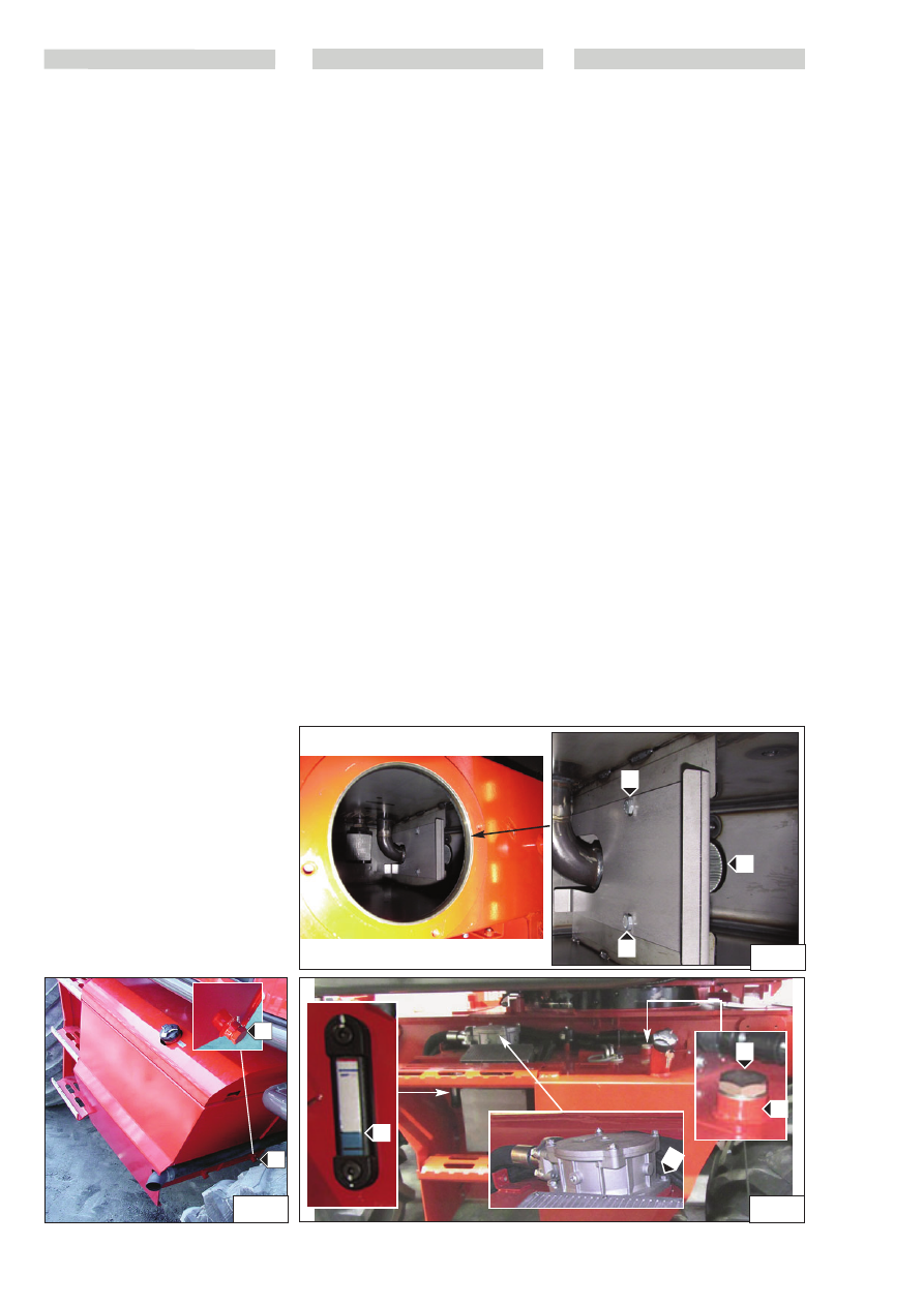
- Change the hydraulic and transmission fluid

Before carrying out these operations, make sure the truck is
on level ground, with the engine switched off.
Place a container under the drainage cap “1” (Fig. E3).
Remove the cap and let the oil flow out.
To speed up the emptying, remove the filler cap “2” (Fig.
E3/1). When the tank is empty remove the hydraulic fluid
filter by removing the four fixing screws “4” (Fig. E3/1)
connected to the tank.
Remove the guard inside the tank removing the two fixing
screws “7” (Fig. E3/2) to access the suction pipe strainer “8”
(Fig.E3/2).

Replacing the hydraulic system suction filter

Unscrew the suction cartridge “8” (Fig.E3/2) at the bottom
of the tank and replace it with another having identical
features; see ("FILTER ELEMENTS AND BELTS TABLE").
Fit the guard inside the tank “7” (Fig. E3/2). 

Fill the tank.

Refit and tighten the drainage plug “1” (Fig. E3). Fill the oil
tank (see "LUBRICANTS”) through filler hole “5” (Fig.E3/1)
until the level of the oil is equidistant from the lower and
upper reference markings of the level indicator “6”
(Fig.E3/1). Check for leaks from the drainage hole. Fit the
cap on tank “2” (Fig. E3/1).

E3 -

Transmissie- en hydraulische olie vervangen

Voor deze handelingen te verrichten, controleren of de
heftruck zich op een horizontale ondergrond bevindt en de
motor uit staat.
Een bak plaatsen onder de aftapdop “1” (fig.E3). Verwijder
de dop en laat de olie weglopen.
Om de tank sneller te legen, de vuldop

“2” (fig.E3/1) verwijderen. Als de tank leeg is het filter van

de hydraulische olie demonteren door de vier
bevestigingsschroeven “4” (fig.E3/1) aan de tank te
verwijderen.
Demonteer het carter in de tank door de twee
bevestigingsschroeven “7” (fig.E3/2) te verwijderen om bij
de zuigkorf “8” (fig.E3/2) te kunnen komen.

Vervangen van het aanzuigfilter van de hydraulische
installatie

Draai de aanzuigpatroon “8” (fig.E3/2) op de bodem van de
tank los en vervang hem door één met dezelfde
eigenschappen (zie "TABEL FILTERELEMENTEN EN RIEMEN").
Monteer het carter in de tank “7” (fig.E3/2). 

De tank vullen.

De aftapdop “1” (fig.E3) weer plaatsen en vastdraaien. Vul
de tank met olie (zie "SMEERMIDDELEN”) door de
vulopening “5”(fig.E3/1) totdat het oliepeil midden tussen
het onderste en bovenste verwijzingsteken staat van de
oliepeilmeter “6” (fig.E3/1). Controleer eventuele lekken uit
de aftapopening. Plaats de afsluitdop van de tank “2”
(fig.E3/1).

E3

- Sostituire olio idraulico e trasmissione

Prima di fare queste operazioni, assicuratevi che il carrello
sia su di una superficie orizzontale e che il motore sia 
spento. 
Mettere un recipiente sotto il tappo di svuotamento 
“1” (fig.E3). Togliere il tappo e lasciare defluire l’olio. 
Per affrettare lo svuotamento, togliere il tappo di
riempimento “2” (fig.E3/1). Quando il serbatoio sarà vuoto
smontare il filtro dell’olio idraulico togliendo le quattro viti
di fissaggio “4” (fig.E3/1) al serbatoio.
Smontare il carter dentro  al serbatoio togliendo le due viti
di fissaggio “7” (fig.E3/2) per  per accedere alla succhieruola
d’aspirazione “8” (fig.E3/2).

Sostituzione del filtro di aspirazione  impianto 
idraulico

Svitare la cartuccia di aspirazione “8” (fig.E3/2) situata sul
fondo del serbatoio  e sostituirla con una di uguali
caratteristiche, vedi ("TABELLA ELEMENTI FILTRANTI E
CINGHIE").
Montare il carter dentro  al serbatoio  “7” (fig.E3/2).

Riempire il serbatoio. 

Rimettere e serrare il tappo di svuotamento “1” (fig.E3).
Riempire il serbatoio d’olio (vedere "LUBRIFICANTI”)
attraverso il foro di riempimento “5” (fig.E3/1) fino a quando
il livello dell’olio non é equidistante fra i segni di riferimento
inferiore e superiore dell’indicatore di livello “6” (fig.E3/1).
Controllare eventuali perdite dal foro di svuotamento. 
Mettere il tappo di chiusura del serbatoio “2” (fig.E3/1).

E3/1

6

4

2

5

E3

8

E3/2

7

7

1

3-45

IT

EN

NL

648747 IT

-EN-NL (29/08/2013)

E4 

- Change the front and rear axles differential 

oil

Position the lift truck on a horizontal surface with the I.C.
engine switched off and the differential oil still hot.

Place a container under the drainage caps 2 (Fig. E4) and
drain out the oil. Remove the level cap 3 (Fig.E4) and the
filler cap 1 (Fig.E4) to ensure complete drainage. Refit and
tighten caps 2 (Fig.E4). Fill oil (see ”LUBRICANTS”) through
the filler hole 1 (Fig.E4). The level is correct when the oil
flows out through level hole “3” (Fig. E4). Check for leaks
from the drainage caps. Refit and tighten the level cap 3
(Fig.E4) and the filler cap 1 (Fig. E4). Repeat the operation
for the rear axle differential; remove the rear caps.

E5 

– Change the front and rear wheels reduction 

gear oil

Position the lift truck on a horizontal surface with the I.C.
engine switched off and the reduction gears oil still hot.
Make sure the drainage and level cap 1 (Fig.E5) is oriented
downwards A to allow the oil to flow down easily. Place a
container 2 (Fig. E5) under the drain plug and unscrew it.
Drain out all the oil.
Bring the drainage hole to the horizontal position B, to be
able to check the oil level successively.
Fill oil “3” (Fig. E5) (see ”LUBRICANTS”) through the filler
hole 1 (Fig.E5). The level is correct when the oil flows out
through hole “1” (Fig. E5).
Refit the drainage cap 1 (Fig. E5) and tighten it. Repeat
this operation for each reduction gear.

E4 

- Olie van de differentieel voor- en achteras

vervangen

Zet de heftruck op een horizontale ondergrond met
stilstaande motor en met de olie van de differentieel nog
warm.

Zet een bak onder de aftapdoppen 2(fig.E4) en laat de olie
weglopen. Verwijder de oliepeildop 3 (fig.E4) en de vuldop
1 (fig.E4) om de olie volledig weg te laten lopen. Plaats de
doppen 2 (fig.E4) weer en draai ze vast. Giet de olie (zie
”SMEERMIDDELEN”) door de vulopening 1 (fig.E4). Het
oliepeil is correct als de olie tot aan de oliepeilopening 3
(fig.E4) staat. Controleer de aftapdoppen op eventuele
lekkage. De peildop 3 (fig.E4) en de vuldop 1 (Fig. E4) weer
aanbrengen en vastdraaien. Verricht dezelfde handeling
voor de differentieel van de achteras.

E5 -

De olie van de reductor van de voor- en

achterwielen verversen

Plaats de heftruck met stilstaande motor op een vlak
terrein met nog warme olie in de reductors. Verzeker u
ervan dat de aftap- en oliepeildop 1 (fig.E5) naar beneden
gericht is A zodat de olie beter weg kan lopen. Zet een bak
2 (fig.E5) onder de aftapdop en draai hem los. Laat alle olie
weglopen.
Zet de aftapopening in de horizontale stand B, om later het
oliepeil te kunnen controleren.
De olie 3 (fig.E5) toevoegen (zie “SMEERMIDDELEN") door
de vulopening 1 (fig. E5). Het oliepeil is goed als de olie
door de opening 1 (fig.E5) te voorschijn komt.
Plaats de aftapdop 1 (fig.E5) weer en draai hem vast.
Herhaal deze handeling voor iedere reductor.

E4 

- Sostituire olio differenziale assale anteriore e 

posteriore

Posizionare il carrello su di una superficie orizzontale con il
motore fermo e l’olio del differenziale ancora caldo.

Porre una recipiente sotto i tappi di svuotamento 2(fig.E4)
e lasciare defluire l’olio. Togliere il tappo di livello 3 (fig.E4)
e il tappo di riempimento 1 (fig.E4) per assicurare uno
svuotamento completo. Rimettere e stringere i tappi 
2 (fig.E4). Mettere l’olio (vedere ”LUBRIFICANTI”)
attraverso il foro di riempimento 1 (fig.E4). Il livello è
corretto quando l’olio affiora al foro di livello 3 (fig.E4).
Controllare eventuali perdite dai tappi di svuotamento.
Rimettere e stringere il tappo di livello 3 (fig.E4) e il tappo
di riempimento 1 (Fig. E4). Effettuare la stessa operazione
per il differenziale togliere i tappi posteriore.

E5 

- Sostituire olio riduttore ruote anteriore e 

posteriore

Posizionare il carrello su di una superficie piana, con il
motore fermo e l’olio dei riduttori ancora caldo.
Accertarsi che il tappo di svuotamento e livello 1 (fig.E5)
sia orientato verso il basso A per far defluire meglio l’olio. 
Collocare un recipiente 2 (fig.E5) sotto il tappo di
svuotamento e svitarlo. Lasciare defluire tutto l’olio.
Portare il foro d’uscita in posizione orizzontale B, per poter
controllare successivamente il livello olio. 
Metter l’olio 3 (fig.E5) (vedere “LUBRIFICANTI”) attraverso
il foro di livello 1 (fig. E5). Il livello è corretto quando l’olio
affiora dal foro 1 (fig.E5). 
Rimettere il tappo di svuotamento 1 (fig.E5) e serrarlo.
Ripetere questa operazione per ciascun riduttore.

E5

A

B

2

3

1

E4

2

1

3-46

IT

EN

NL

648747 IT

-EN-NL (29/08/2013)

1

IT

EN

NL

E6 - 

Change the oil in the 2-speed reduction gear 
on the front axle

Park the lift truck on a horizontal surface with the I.C.
engine switched off and the reduction gear oil still hot.
Place a container under the drainage cap “1” (Fig. E6).
Remove the cap 1 (Fig. E6) and drain out the oil. Remove
the oil level and filler cap “2” (Fig. E6 to ensure complete
drainage. Refit and tighten the cap 1 (Fig. E6). Fill oil (see
”LUBRICANTS”) through the level and filler hole 2 (Fig. E6).
The oil level is correct when it flows out through the
opening.
Refit and tighten the level and filler cap “2” (Fig. E6).
Check for leaks from the drainage cap.

E7 

- Clean the fuel tank

It is forbidden to smoke or use free flames during this
intervention.
Never attempt to weld or carry out other operations,
taking into account risks of explosion or fire.

Position the truck on a level surface, with the engine
switched off.
Unscrew the tank filler cap 2 (Fig. E7) then place a suitable
container under the drainage cap 1 (Fig. E7) and unscrew
the cap.
Drain out the fuel and pour 10 litres of clean fuel through
the filler hole 2 (Fig. E7) to remove impurities, if any.
Refit and tighten the drainage cap 1 (Fig. E7). Fill the tank
with clean fuel and refit the cap 2 (Fig. E7).

E6 

- De olie van de 2 snelheden reductor op de

vooras verversen

De heftruck op een vlak stuk grond zetten met de motor
uit en de olie van de reductor nog warm. Zet een bak
onder de aftapdop 1(fig.E6). Verwijder de dop 1(fig.E6) en
laat de olie weglopen. Verwijder de oliepeil- en vuldop 2
(fig.E6) om de olie volledig weg te laten lopen. Plaats de
dop 1 (fig.E6) weer en draai hem vast. Giet de olie (zie
“SMEERMIDDELEN”) door de oliepeil- en vulopening 2
(fig.E6). Het niveau is juist als de olie tot aan de rand van
de opening staat.
De oliepeil- en vuldop 2 weer op zijn plaats brengen en
aandraaien (fig.E6).
Controleer eventuele lekken van de aftapdop.

E7 

- De brandstoftank schoonmaken

Het is absoluut verboden te roken tijdens deze ingreep
of met een vlam in de buurt te komen.
Nooit proberen zelf te lassen of andere
werkzaamheden te verrichten, dit zou ontploffing of
brand ten gevolge kunnen hebben.

Zet de heftruck op een horizontale ondergrond met
stilstaande motor.
Draai de vuldop 2 (fig. E7) van de  tank los en plaats dan
een geschikte bak onder de aftapdop 1 (fig. E7) en draai de
dop los.
Laat de brandstof weglopen en giet 10 liter schone
brandstof door de vulopening 2 (fig. E7) om eventuele
onzuiverheden te verwijderen.
De aftapdop 1 weer vastdraaien (fig. E7). Vul de tank met
schone brandstof en plaats de dop weer 2 (fig. E7).

E6

- Sostituire olio riduttore 2 velocità sul ponte 

anteriore

Posizionare il carrello su di una superficie orizzontale con il
motore fermo e l’olio del riduttore ancora caldo. Porre un
recipiente sotto al tappo di svuotamento 1(fig.E6). Togliere
il tappo 1(fig.E6)  e lasciare defluire l’olio. Togliere il tappo
di livello e riempimento 2 (fig.E6) per assicurare uno
svuotamento completo. Rimettere e serrare il tappo 1
(fig.E6). Mettere l’olio (vedere “LUBRIFICANTI”) attraverso
il foro di livello e riempimento 2 (fig.E6). Il livello é corretto
quando l’olio affiora dal foro.
Rimettere e stringere il tappo di livello e riempimento 
2 (fig.E6).
Controllare eventuali perdite dal tappo di svuotamento.

E7 

- Pulire serbatoio combustibile

È vietato fumare o avvicinarsi con una fiamma libera
durante questo intervento.
Non cercare mai di effettuare da soli una saldatura o
qualsiasi altra operazione, tenuto conto dei 
rischi di esplosione o di incendio.

Posizionare il carrello su di una superficie orizzontale e con il
motore fermo.
Svitare il tappo 2 (fig. E7) di riempimento serbatoio  poi
collocare un recipiente adeguato sotto il tappo di
svuotamento 1 (fig. E7) e svitare il tappo. 
Lasciare defluire  il carburante ed introdurre 10 litri  di  
carburante pulito attraverso il foro di riempimento  2 (fig.
E7) per eliminare eventuali impurità. 
Rimontare e serrare il tappo di svuotamento1 (fig. E7).
Riempire il serbatoio con carburante pulito e rimettere il
tappo  2 (fig. E7).

E6

E7

2

3-47

IT

EN

NL

648747 IT

-EN-NL (29/08/2013)

IT

EN

NL

E8 - 

Check the telescopic boom outer chains for wear  

MRT 1840  ST3B (400°- 360°)

The wear on these chains appears:
1) On the joints, resulting in lengthening of the chain.
2) On the profile of the lateral plates due to contact with the 

pulleys and the guide systems.

3) On the sides of the external plates and on the heads of 

the pins due to contact with the flanges of the pulleys or 
with guide devices, if any.

E8.1 

- Check the extension for wear

MRT 1840  ST3B (360°) 

To keep the stretching of the chain under control it is
advisable to provide an adjustment module as attachment.
Since the wear will most probably be uniform along the
entire length of the chain, the measuring must be done in
sections (divide the total length in 5 – 15 sections) which
must be appropriately identified. The initial measurement
must be taken which serves as reference for the successive
measurements, and it is necessary to take into account that
all successive measurements must be done on the same
sections.
After a few measurements, it is possible to identify the
sections which are most subject to wear, and successive
measurements can therefore be limited to these sections.
The measurement can be done using a sufficiently long
sliding calliper or a millimetre ruler. The reference may be
the head of the pins or the profile of the plate.
The measurement must be done with the chain taut (keep
the boom extension lever pressed for a few seconds) in the
rectilinear section.
The maximum extension limit is fixed at 2% taking into
account the weakening due to removal of material from
parts which influence the features of resistance of the chain
and due to wear of the hard surface layers (for cemented
pins).

E8.2 

- Check the lateral plates profile

MRT 1840  ST3B (360°) 

After having visually identified the section of the chain
where this phenomenon is more evident, the actual height
of the eyelet of the plates must be measured with a gauge
and compared with the initial measurement.

The maximum wear limits are fixed as follows (reference
E8/1):

wear only on one side: 

[(H-H1):H]x100 

2%

wear on two sides:

[(H-H2):H]x100 

3,5%

E8 - 

De slijtage van de externe kettingen van de

telescopische arm nakijken

MRT 1840 ST3B (400°- 360°)

De slijtage aan deze kettingen vindt plaats:
1) Op de geledingen met verlenging van de ketting tot
gevolg.
2) Op het profiel van de zijplaten door contact met de
kettingschijven en de geleidesystemen.
3) Op de zijkanten van de buitenplaten en op de koppen
van de pennen door contact met de flenzen van de
kettingschijven of met eventuele geleidesystemen.

E8.1 

- Controle van de verlenging door slijtage

MRT 1840 ST3B (360°)

Om de verlenging van de ketting onder controle te houden
is het raadzaam een registratieblad te gebruiken zoals in
bijlage.
Daar de slijtage waarschijnlijk niet over de hele lengte van
de ketting gelijk zal zijn, moet de meting per stuk ketting
uitgevoerd worden (verdeel de totale lengte in 5 - 15
stukken) die naar behoren geïdentificeerd moeten worden.
De aanvankelijke maat moet opgemeten worden ter
verwijzing voor de daaropvolgende metingen en deze
metingen moeten op dezelfde stukken worden verricht.
Na enkele metingen kunt u zien welke delen het meest aan
het slijtageverschijnsel zijn blootgesteld en dus kunt u de
daaropvolgende metingen beperken tot deze delen.
De meting kan gemaakt worden met een schuifmaat of
met een in millimeters verdeelde liniaal. Als verwijzing kan
de kop van de pennen of het profiel van de plaat gebruikt
worden.
De meting moet gemaakt worden met gespannen ketting
(de hendel voor het uitschuiven van de arm enkele
seconden ingedrukt houden) op het rechtlijnige stuk.
De maximale limiet voor de verlenging is 2% rekening
houdend met de verzwakking door de verwijdering van
materiaal van delen die de weerstandseigenschappen van
de ketting beïnvloeden en door de slijtage van de harde
oppervlaktelagen (voor gecementeerde pennen).

E8.2 - 

Controle van het profiel van de zijplaten

MRT 1840 ST3B (360°)

Na bekeken te hebben op welk deel van de ketting dit
verschijnsel het duidelijkst is, moet u de effectieve hoogte
van het oog van de platen met een schuifmaat meten en
met de beginhoogte vergelijken.

De volgende maximale slijtagelimieten zijn bepaald (zie
E8/1):

slijtage op één kant: 
[(H-H1):H]x100 

2% 

slijtage op twee kanten:
[(H-H2):H]x100 

3,5%

E8 - 

Controllare l’usura delle catene esterne del 
braccio telescopico

MRT 1840  ST3B (400°- 360°)

L'usura su queste catene si manifesta:
1) Sulle articolazioni con conseguente  allungamento della 

catena.

2) Sul profilo delle piastre  laterali per contatto con le

pulegge e i sistemi di guida.

3) Sui fianche delle piastre esterne e sulle testate dei perni 

per contatto con le flange delle pulegge o con eventuali  
dispositivi di guida.

E8.1 

- Verifica dell’allungamento per usura 

MRT 1840  ST3B (360°) 

Per tenere sotto controllo l'allungamento della catena è
consigliabile predisporre un modulo di registrazione come 
allegato.
Poichè verosimilmente l'usura non sarà uniforme lungo
tutta la lunghezza della catena, la misurazione deve essere
effettuata per tratti (suddividere la lunghezza totale in 
5 - 15 tratti) che vanno opportunamente identificati.
Deve essere rilevata la misura iniziale che serve di
riferimento per quelle sucessive, e va tenuto presente che
tutte le sucessive misurazioni devono avvenire sugli stessi
tratti.
Dopo alcune misure è possibile identificare quali tratti sono
maggiormente sottoposti al fenomeno di usura e quindi le
misurazioni successive possono essere limitate solo a questi
tratti.
La misura può essere fatta o con calibro corsoio
sufficientemente lungo o con riga millimetrata. Il
riferimento può essere o la testa dei perni o il profilo della
piastra.
La misurazione deve essere fatta con la catena in tensione
(tenere premuto per qualche secondo la leva sfilo braccio)
nel tratto rettilineo.
Il limite massimo di allungamento è fissato al 2 % tenendo
conto dell'indebolimento dovuto all'asportazione di
materiale da parti che influiscono sulle caratteristiche
resistenziali della catena e dal consumo degli strati duri
superficiali (per perni cementati).

E8.2 -

Verifica del profilo piastre  laterali

MRT 1840  ST3B (360°) 

Dopo ever visivamente identificato il tratto di catena dove
questo fenomeno è più evidente, con un calibro deve essere
rilevata l'altezza effettiva dell'occhiello delle piastre e
confrontata con quella iniziale.

Vengono fissati questi limiti di usura 
massima (fare riferimento E8/1):

consumo su un solo lato:  

[(H-H1):H]x100 

2%

consumo su due lati: 

[(H-H2):H]x100 

3,5%

3-48

IT

EN

NL

648747 IT

-EN-NL (29/08/2013)

IT

EN

NL

De hoge specifieke belastingen tussen het profiel van de
platen en de kettingschijven veroorzaakt niet alleen slijtage
maar ook het opstuiken van materiaal op de randen van de
platen wat kan leiden tot blokkering van de geledingen.
Als er geledingen blokkeren moet de ketting vervangen
worden (de plaatselijke dealer raadplegen).

E8.3 

- Controle op de zijkant van de ketting

MRT 1840 ST3B (360°)

Deze slijtage is veroorzaakt door een verkeerde interactie
tussen de ketting en de kettingschijven of andere
zijgeleidingselementen. De zijdelingse wrijving op de
kettingschijven kan toegeschreven worden aan niet
gebalanceerde lasten of aan niet uitgelijnde kettingschijven
en/of vasthaaksystemen. 
De slijtage op de koppen van de pennen mag de grip ervan
op de plaat niet beïnvloeden, om te voorkomen dat deze
los kan raken.
De slijtage op de rand van de plaat veroorzaakt
verzwakking ervan.
Als u een slijtage op de kop van de pennen van meer dan
25% van de uitstekende rand opmerkt of van meer dan
20% van de dikte op de buitenkant van de platen (zie
E8/1-E8/2), dan moet de ketting vervangen worden en
moet, voor de nieuwe te monteren, de oorzaak van dit
defect opgespoord worden.

Slijtage % penkop: 
(R1:R)x100 

25% 

Slijtage % plaatrand: 
(S1:S)x100 

20%

Als er te veel slijtage is moet de ketting vervangen worden
(de plaatselijke dealer raadplegen).

E9 

- De slijtage van de glijschoenen van de

telescopische arm controleren.

Raadpleeg voor deze handelingen uw vertegenwoordiger
of dealer.

The high specific pressures between the plates profile and
pulleys can cause not only wear but burrs of material on the
edge of the plates which could give rise to blocked joints.
If the joints are found to be blocked, the chain must be
replaced (contact the area dealer).

E8.3-

Check the sides of the chain

MRT 1840  ST3B (360°) 

This wear is caused by improper interaction of the chain
with the pulleys or other lateral guide elements. Rubbing of
the sides against the pulleys can be induced by offset loads
or by pulleys and/or hook-up devices that are not aligned.
Wear on the heads of the pins must not affect their hold on
the plate, as the pins can otherwise become slack.
Wear of the edge of the plate causes it to weaken.
If the wear on the heads of the pins is found to be more than
25% of the projection of the riveting or on the outer surface
of the plates more than 20% of the thickness (refer to E8/1-
E8/2), the chain must be replaced and the cause of the
operating fault must be identified before fitting a new
chain.

% wear of head of pin: 

(R1:R)x100 

25%

wear on edge of plate:

(S1:S)x100 

20%

En cas d’usure excessive, remplacer la chaîne (contacter le
concessionnaire).

E9

- Check the telescopic boom sliding blocks for 

wear

For these operations, consult your agent or dealer.

Le elevate pressioni specifiche tra profilo piastre e pulegge
possono causare, oltre che usura, anche rifollamento di
materiale sullo spigolo delle piastre che può dar luogo ad
articolazioni bloccate.
Se si riscontrano articolazioni bloccate, la catena deve essere
sostituita (consultare il concessionario di zona).

E8.3 

- Verifica sul fianco della catena

MRT 1840  ST3B (360°) 

Questa usura è causata da una impropria interazione della
catena con le pulegge o altri elementi di guida laterale. Lo
sfregamento laterale sulle pulegge può essere indotto a
carichi disassati o da pulegge e/o dispositivi di aggancio non
allineati.
L'usura sulle testate dei perni non deve compromettere la
tenuta di questi sulla piastra, per evitare che questa possa 
sfilarsi.
L'usura sul bordo della piastra crea indebolimento della
stessa.
Nel caso che si riscontri un consumo sulla testata dei perni
oltre il 25% della sporgenza di ribattitura o sul fianco 
esterno delle piastre oltre il 20% dello spessore (fare
riferimento E8/1-E8/2), la catena deve essere sostituita e,
prima di montare la nuova, va ricercata la causa di questo
malfunzionamento.

Consumo % testata perno:

(R1:R)x100 

25%

Consumo % bordo piastra:

(S1:S)x100 

20%

Se si riscontrano usure eccessive, la catena deve essere
sostituita (consultare il concessionario di zona).

E9 

-  Controllare usura pattini del  braccio 

telescopico.

Per queste operazioni, consultare il vostro agente o
concessionario.

H

H1

H2

G

R

R1

S

S1

F

E

CATENE ESTERNE IN mm
OUTER CHAINS  IN mm
EXTERNE KETTINGEN IN mm

E

5,95

F

19,05

G

42,25

H

15,5

R

2,39

S

2,005

E8/3

3-49

IT

EN

NL

648747 IT

-EN-NL (29/08/2013)

IT

EN

NL

E10

- Change the rotation gear reducer oil

Position the forklift truck, with the turret aligned, on a flat
surface, retract and extend the telescopic boom completely
and then rotate the turret to the RH through +/- 60°, for
better access to the filling points of the rotation reduction
gear (Fig. E10); stop the I.C. engine and wait for the
hydraulic fluid to cool down.

To change the oil in the upper part place a container under
the main drainage cap 3 (Fig. E10/1), slacken it and drain
out the oil. Refit and tighten drainage plug “3” (Fig. E10/1)).
Fill through hole 1 (see ”Lubricants”). The level is correct
when the oil flows out through hole “2” (Fig. E10/1).
To change the oil in the rotation reduction gear brake part
place a container under the brake fluid drainage cap 5 (Fig.
E10/1), slacken it and drain out the oil. Remove the filler cap
4 (Fig.E10/1) to make drainage easier. Refit and tighten
brake oil drainage plug “5” (Fig. E10/1). Fill through hole 4
(Fig. E10/1) (see ”Lubricants”).

Lubricate the reduction gear bearings with specific grease
(see “Lubricants”) by means of the grease nipple 4
(Fig.E10/1).

E10 

- De olie van de rotatiereductor verversen

Zet de heftruck met de zwenkkop recht op een vlakke
ondergrond, trek de telescopische arm helemaal in, hef
hem volledig op en draai dan de zwenkkop naar rechts
over +/- 60°, om beter bij de vulplaatsen van de reductor
voor de rotatie van de zwenkkop (fig.E10) te kunnen
komen; zet de verbrandingsmotor uit en wacht tot de
hydraulische olie is afgekoeld.

Om de olie in de bovenkant te vervangen moet u een bak
onder de aftapdop 3 (fig.E10/1) plaatsen, hem losdraaien
en de olie weg laten lopen. Plaats de aftapdop 3
(fig.E10/1) weer en draai hem vast. Vullen door de opening
1 (zie “Smeermiddelen”). Het niveau is goed als het tot aan
de opening 2 (fig.E10/1) staat en daardoor naar buiten
komt.
Om de olie in het deel van de rotatiereductorrem te
vervangen moet u een bak onder de aftapdop van de
remolie 5 (fig.E10/1) plaatsen, hem losdraaien en de olie
weg laten lopen. Verwijder de vuldop 4 (fig.E10/1) zodat
de olie makkelijker wegloopt. Plaats de aftapdop van de
remolie 5 (fig.E10/1) weer en draai hem aan. Vullen door
de opening 4 (fig.E10/1) (zie “Smeermiddelen”).

Smeer de lagers van de reductor 

met specifiek vet (zie

“Smeermiddelen”) door middel van de smeernippel 4
(fig.E10/1).

E10 

- Sostituire l’olio del riduttore rotazione

Posizionare il carrello, con torretta allineata, su di una
superficie piana, rientrare e sollevare completamente il
braccio telescopico e poi ruotare la torretta a destra di +/-
60°, per accedere meglio ai punti di riempimento del
riduttore rotazione (fig.E10); fermare il motore termico e
attendere che si raffreddi l’olio idraulico.

Per la sostituzione dell’olio nella parte superiore porre un
recipiente sotto il tappo di scarico principale 3 (fig.E10/1),
allentarlo e lasciare defluire l’olio. Rimettere e stringere il
tappo di scarico 3 (fig.E10/1). Eseguire il riempimento
attraverso il foro 1 (vedi “Lubrificanti”). Il livello é corretto
quando l’olio affiora e defluisce dal foro 2 (fig.E10/1). 
Per la sostituzione dell’olio nella parte freno riduttore
rotazione porre un recipiente sotto il tappo di scarico olio
freno 5 (fig.E10/1), allentarlo e lasciare defluire l’olio.
Togliere il tappo di riempimento 4 (fig.E10/1) per facilitare
lo svuotamento. Rimettere e stringere il tappo di scarico
olio freno 5 (fig.E10/1). Eseguire il riempimento attraverso
il foro 4 (fig.E10/1)  (vedi “Lubrificanti”).

Lubrificare i cuscinetti del riduttore

con grasso

specifico (vedi “Lubrificanti”) tramite l’ingrassatore 4
(fig.E10/1).

1

2

E10/1

E10

MRT 1840  ST3B (360°) 

MRT 1440  ST3B (400°) 
MRT 1640  ST3B (400°)  

MRT 1840  ST3B (400°) 

3-50

IT

EN

NL

648747 IT

-EN-NL (29/08/2013)

IT

EN

NL

2

1b

2

4

3

1a

E11 -

Check the wear and increment of the play of the 

slewing ring bearings

The play of bearings in a new vehicle, tested in the factory, has
an initial reference value of 0.05 - 0.25 mm.

The maximum wear limit value of the play of the bearing is 2.2
mm and if a higher value is found during a check, the slewing
ring bearing must be replaced. With increase in wear, intensify
the checks.

Testing must be done using a comparator with clock with
centesimal scale, with bearing stopped.
The oscillation will be measured between a condition with
negative moment and one with positive moment.

Position the forklift truck on a flat surface, without load and
with the boom lifted to the maximum possible extent.
Then connect the comparator between the turret and chassis, as
seen in the photo “A” (Fig. E11).
Check to make sure everything is ok, then lower the boom to
bring it near the comparator and reset the clock. (negative
condition).
Then raise the boom all the way and read the axial play value on
the clock (positive condition).

The values measured compared with the maximum limit value
provide the extent of wear.
la valeur de limite maximum, donnet l'ampleur de l'usure.

E12 - 

Change the heating tank fuel filter

MRT 1840  ST3B (360°)

It is forbidden to smoke

or use free flames during this intervention.
Never attempt to weld or carry out other operations,
taking into account risks of explosion or fire.

Position the truck on a level surface, with the engine
switched off.
Unscrew the tank filler cap 4 (E12/1), then place a suitable
container under the drainage cap 1a (E12/2) and unscrew
the tube clamp 1b (E12/2) to drain out the fuel.

Unscrew the clamps 2 (E12/2) and release the tubes to
drain out the fluid inside.

Remove the filter 3 (E12/2) and replace with a new one
have identical features; see “Filters and belts Table”.

Reconnect the fuel pipes with the filter and the tank.

E11 

- De slijtage en de toename van de speling van

de lagers van het draaistel nakijken

De speling van de lagers in een nieuw voertuig,
geregistreerd in de fabriek, heeft als 

beginwaarde 

ter

verwijzing 

0,05 ÷ 0,25 mm

.

De maximale slijtagelimiet  

van de speling van de lager

is 2,2 mm 

en als tijdens een controle een hogere waarde

wordt gemeten, dan moet het draaistel vervangen worden.
Bij toenemende slijtage vaker controleren.

De test dient te worden uitgevoerd middels meetklok met
metrische schaalverdeling, met stilstaande lager.
Er wordt een oscillatie geregistreerd tussen een
omstandigheid met negatief moment en één met positief
moment.

Zet de heftruck op een vlak oppervlak, zonder lading en met
de arm tot het maximum opgeheven.
Dan het meetklokje tussen de zwenkkop en het frame
plaatsen, zoals op foto “A” (Fig. E11).
Wanneer u gecontroleerd heeft of alles in orde is brengt u de
arm naar beneden totdat deze dichtbij het meetklokje komt
en stelt u de klok op nul. (negatieve situatie).
Dan de arm weer tot een maximum opheffen en de waarde
lezen van de axiale speling op de klok (positieve situatie).

De geregistreerde waarden vergeleken met de maximale
limietwaarde, bieden de graad van slijtage.

E12 

Het filter van de brandstoftank voor de

verwarming vervangen

MRT 1840 ST3B (360°)

Het is absoluut verboden te roken tijdens deze
procedure of met een vlam in de buurt te komen.
Probeer nooit eigenhandig te lassen of andere
werkzaamheden te verrichten, gezien
het gevaar voor ontploffing of brand.

Zet de heftruck op een horizontale ondergrond met
stilstaande motor.
Draai de vuldop 4 (E12/1) van de tank los en zet dan een
geschikte bak onder de aftapdop 1a (E12/2) en draai het
klembandje van de slang 1b (E12/2) los om de brandstof
weg te laten lopen.

Draai de klembandjes 2 (E12/2) los en haal de slangen los
om de brandstof erin af te voeren.

Verwijder het filter 3 (E12/2) en vervang het met een nieuw
filter met dezelfde eigenschappen, zie “tabel filters en
riemen”.

Verbind de brandstofslangen weer met het filter en de tank.

E11 

- Verificare l'usura e l'incremento  del gioco dei 

cuscinetti della ralla

Il gioco dei cuscinetti a macchina nuova, rilevato in Fabbrica,
ha come 

valore iniziale

di riferimento 

0,05 ÷ 0,25 mm

.

Il valore di limite massimo d' usura 

del gioco del

cuscinetto

è di  2,2  mm

e  se durante una verifica viene

misurato un valore superiore,  è necessario provvedere alla
sostituzione della ralla. All'aumentare dell'usura
intensificare i controlli.

La prova va eseguita tramite comparatore ad orologio con
scala centesimale, a cuscinetto fermo.
Si rileverà l'oscillazione tra una condizione con momento
negativo ed una con momento positivo.

Posizionare il carrello su di una superficie piana,  senza
carico e con il braccio sollevato al massimo.
Quindi collocare il comparatore tra la torretta e il telaio,
come in foto “A” (Fig. E11).
Controllato che sia tutto in ordine abbassare il braccio fino
ad avvicinarlo al comparatore ed azzerare l'orologio.
(condizione negativa).
Poi sollevare il braccio al max e leggere il valore di gioco
assiale sull'orologio (condizione positiva).

I valori rilevati confrontati con il valore di limite massimo,
forniscono l'entità dell' usura.

E12

-

Sostituire il filtro carburante del 
serbatoio riscaldamento

MRT 1840  ST3B (360°)

È vietato fumare o avvicinarsi con una fiamma libera
durante questo intervento.
Non cercare mai di effettuare da soli una saldatura o
qualsiasi altra operazione, tenuto conto dei 
rischi di esplosione o di incendio.

Posizionare il carrello su di una superficie orizzontale e con il
motore fermo.
Svitare il tappo 4 (E12/1) di riempimento serbatoio  poi
collocare un recipiente adeguato sotto il tappo di 
svuotamento 1a (E12/2) e svitare la fascetta del tubo 1b
(E12/2) per lasciare defluire  il carburante.

Svitare le fascette 2 (E12/2)  e sganciare i tubi per scaricare
il carburante all’interno.

Rimuovere il filtro  3 (E12/2) e sostituirlo con uno nuovo di
uguali caratteristiche, vedere “tabella filtri e cinghie”. 

Ricollegare i tubi del carburante con il filtro ed il serbatoio.

A

E11

E12

3-51

IT

EN

NL

648747 IT

-EN-NL (29/08/2013)

IT

EN

NL

E13 -

Check the safety belt

The forklift truck must not be used if the seat belt is
defective (Fixing, lock, seams, tears, etc.).
Repair or change the seat belt immediately.

SAFETY BELT WITH TWO FIXING POINTS

- Check the following points:
• The fixing of the anchoring points on the seat.
• Cleaning the belt and locking mechanism.
• Clicking of the locking mechanism.
• The state of the belt (tears, fraying).

AUTOMATIC SAFETY BELT WITH TWO FIXING POINTS

- Check the afore-mentioned points and those below:
• Correct sliding of the belt.
• The state of the winder plates.
• The locking of the winder mechanism by pulling the belt
with one firm pull.
NOTE: After an accident, replace the safety belt.

E13 

- Veiligheidsgordel nakijken

In geen geval de heftruck gebruiken als de
veiligheidsgordel defect is (bevestiging, blokkering,
naden, scheuren, enz.).
Repareer of vervang onmiddellijk de
veiligheidsgordel.

VEILIGHEIDSGORDEL MET TWEE VERANKERINGSPUNTEN

- De volgende punten controleren:
• De bevestigingspunten aan de stoel.
• Of de gordel en het vergrendelingsmechanisme schoon
zijn.
• Of het vergrendelingsmechanisme naar behoren werkt.
• De staat van de gordel (scheuren, rafels).

AUTOMATISCHE VEILIGHEIDSGORDEL MET TWEE
VERANKERINGSPUNTEN

- De hierboven staande punten en de volgende controleren:
• Of de riem goed wordt opgerold.
• De staat van de afdekplaatjes van het oprolmechanisme.
• Of het oprolmechanisme geblokkeerd wordt door stevig
aan de riem te trekken.
N.B. : Na een ongeval moet de veiligheidsgordel vervangen
worden.

E13 

- Controllare la cintura di sicurezza

Non è possibile in alcun caso utilizzare il carrello
elevatore con la cintura di sicurezza difettosa
(fissaggio, blocco, cuciture, strappi, ecc.).
Riparare o sostituire immediatamente la cintura di
sicurezza.

CINTURA DI SICUREZZA A DUE PUNTI DI ANCORAGGIO

- Verificare i punti seguenti:

• Il fissaggio dei punti di ancoraggio sul sedile.
• La pulizia del nastro e del meccanismo di bloccaggio.
• Lo scatto del meccanismo di bloccaggio.
• Lo stato del nastro (strappi, sfilacciature).

CINTURA DI SICUREZZA AUTOMATICHE A DUE PUNTI DI
ANCORAGGIO

- Verificare i punti sopraelencati e quelli seguenti:

• Lo scorrimento corretto del nastro.
• Lo stato delle maschere dell’arrotolatore.
• Il bloccaggio del meccanismo dell’arrotolatore tirando il 

nastro con un colpo secco.

NOTA: A seguito di un incidente, sostituire la cintura di 

sicurezza.


Content      ..     20      21      22      23     ..