Manitou MRT 1440 ST3B (400°), MRT 1640 ST3B (400°), MRT 1840 ST3B (400°-360°). MANUALE D’ISTRUZIONI - 16
 

  Index      Manuals     Manitou MRT 1440 ST3B (400°), MRT 1640 ST3B (400°), MRT 1840 ST3B (400°-360°). MANUALE D’ISTRUZIONI


Search            copyright infringement  


Content      ..     14      15      16      17     ..


Manitou MRT 1440 ST3B (400°), MRT 1640 ST3B (400°), MRT 1840 ST3B (400°-360°). MANUALE D’ISTRUZIONI - 16


82

IT

EN

NL

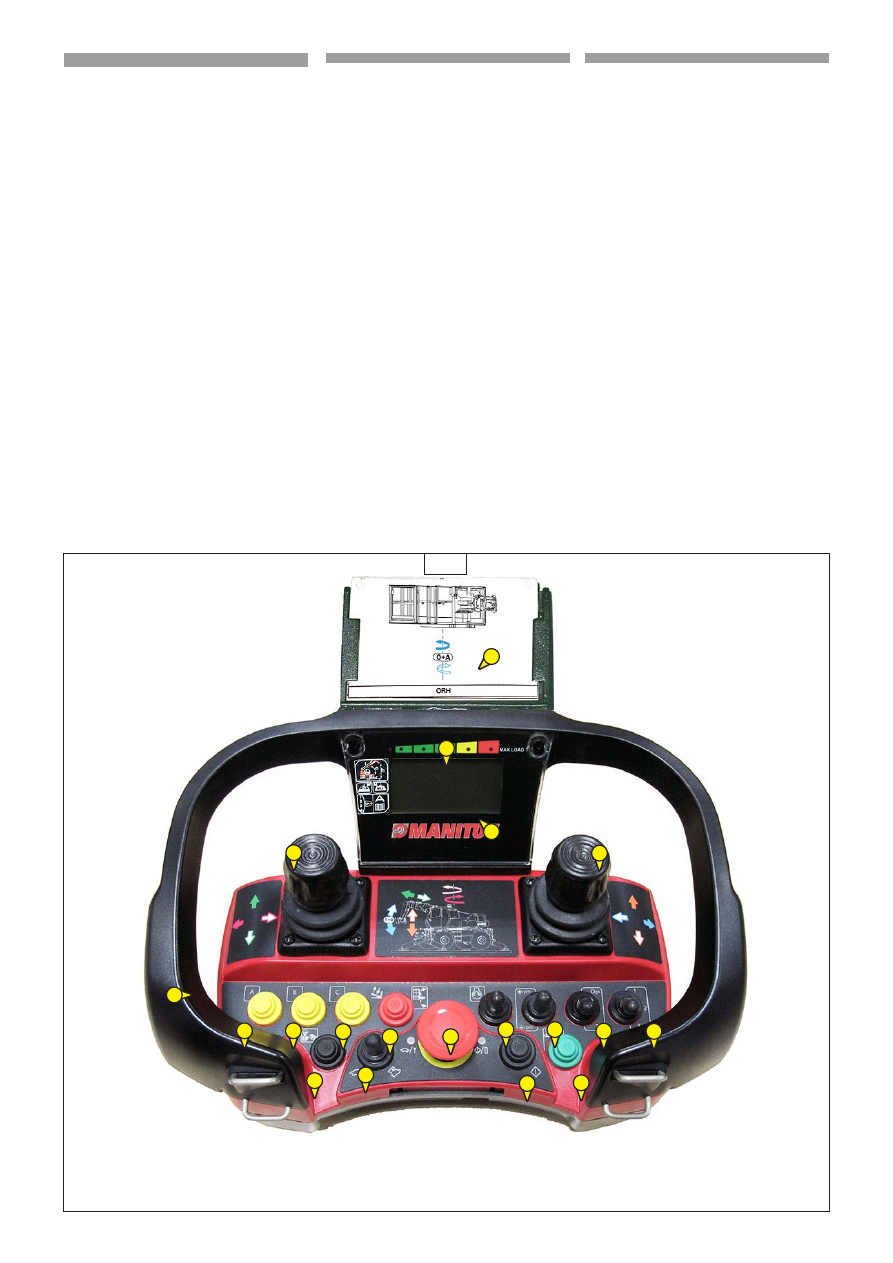
PULSANTIERA 

1 - Display funzioni macchina e stato 

      del carico 

(Vedi immagine 43, punto 1)

2 - Comandi macchina e accessorio:

      • manipolatori per il controllo 

        proporzionale, 

(Vedi immagine 43, punto 2)


      • selettori, pulsanti e interruttori che 

        consentono l’attivazione di funzioni 

        digitali ON/OFF 

(Vedi immagine 43, punto 2)

3 - Pulsante a fungo per la funzione di   

      arresto d’emergenza (STOP) 


(Vedi immagine 43, punto 3)

4 - Interruttore avviamento motore


(Vedi immagine 43, punto 4)

5 - Attivazione pulsantiera 


(Vedi immagine 43, punto 5)

6 - Pulsante elettropompa d’emergenza 

      per il salvataggio del cestello porta 

      persone 

(Vedi immagine 43, punto 6)

7 - Acceleratore/decelatore giri motore

             (Vedi immagine 43, punto 7)

8 - Interruttore velocità movimenti idraulici

      con accessorio gru 


(Vedi immagine 43, punto 8)

9 - Presa per filocomando (non utilizzata)

              (Vedi immagine 43, punto 9)

10 - Schede movimenti accessori

               (Vedi immagine 43, punto 10)

11 - Scorrimento pagine display

                (Vedi immagine 43, punto 11)

1

10

2

2

2

2

7

4

2

2

2

2

3

8

5

11

6

1

9

43

KNoPPENBoRD 

1 - Display machinefuncties en staat van de lading 

(Zie afbeelding 43, punt 1)

2 - Bedieningen machine en werktuig:

• stuurknuppels voor proportionele besturing 

(Zie 

afbeelding 43, punt 2)


• keuzeschakelaars, knoppen en schakelaars 

waarmee digitale ON/OFF functies geactiveerd 

kunnen worden 

(Zie afbeelding 43, punt 2)

3 - Paddelstoelvormige knop voor de noodstop 

(STOP) 

(Zie afbeelding 43, punt 3)

4 - Motor startschakelaar.

(Zie afbeelding 43, punt 4)

5 - Activering knoppenbord 

(Zie afbeelding 43, punt 5)

6 - Knop elektrische noodpomp voor de 

reddingsprocedure van het personenplatform 

(Zie afbeelding 43, punt 6)

7 - Knop voor versnellen/vertragen motortoerental

(Zie afbeelding 43, punt 7)

8 - Schakelaar voor snelheid hydraulische 

bewegingen met kraanwerktuig 

(Zie afbeelding 43, punt 8)

9 - Contactpunt voor draadbediening (niet 

gebruikt)

(Zie afbeelding 43, punt 9)

10 - Kaarten werktuigbewegingen

(Zie afbeelding 43, punt 10)

11 - Displaypagina’s doorlopen

(Zie afbeelding 43, punt 11)

PUSHBUTToN PANEL 

1 - Machine functions and load status 

display 

(See image 43, point 1)

2 - Vehicle and attachment controls:

• manipulators for the proportional control 

(See image 43, point 2)


• selectors, pusbuttons and switches which 

allow activation of the digital functions ON/

OFF 

(See image 43, point 2)

3 - Mushroom-shaped pushbutton for 

emergency stop function (STOP) 

(See image 43, point 3)

4 - Engine start-up switch

(See image 43, point 4)

5 - Pushbutton panel activation 

(See image 43, point 5)

6 - Emergency motor pump button for 

platform rescue 

(See image 43, point 6)

7 - Engine rpm accelerator/decelator

(See image 43, point 7)

8 - Hydraulic movements speed switch with 

crane attachment 

(See image 43, point 8)

9 - Socket for wired control (not used)

(See image 43, point 9)

10 - Attachments movements charts

(See image 43, point 10)

11 - Display pages scrolling

(See image 43, point 11)

83

IT

EN

NL

Istruzioni operative

- Posizionare l’interruttore di accensione    

   dell’unità centrale su REMOTE.

- Sbloccare il pulsante d’emergenza della 

   pulsantiera e della macchina.

- Inserire una batteria carica nel vano della 

  pulsantiera.

- Premere e il LED rosso si accenderà fisso.

- Il sistema è ora pronto per lavorare.  

  L’operatore deve essere consapevole 

  di tutte le funzioni dei manipolatori 

  proporzionali e ON/OFF prima di iniziare a 

  manovrare.

- Per disattivare il sistema sia il pulsante 

  d’emergenza a fungo della pulsantiera che

  quello installato sulla macchina devono 

  essere premuti. Il pulsante d’emergenza 

  della pulsantiera deve sempre essere 

  premuto quando il pulsantiera non è 

  in uso.

  Ciò vale anche per brevi interruzioni, per 

  esempio, se il conducente desidera

  spostare la macchina.

- Per garantire un funzionamento 

  prolungato nel tempo, e per ragioni di 

  sicurezza, la pulsantiera deve essere 

  tenuta dentro la cabina di guida quando 

  non è utilizzata. E’ buona norma inoltre 

  pulirla regolarmente con un panno umido, 

  per esempio.

BATTERIA 

(Vedi immagine 44)

La batteria, di tipo ricaricabile (

NiMH

), 

eroga una tensione di 7,2Vcc. 

La batteria è sigillata, resistente agli agenti 

atmosferici e protetta contro i cortocircuiti.

Inserita nella parte inferiore della 

pulsantiera  permette l’utilizzo via

radio. La sua sostituzione è rapida e molto 

semplice da effettuare.

funzionamento con la batteria

• L’operatività di una batteria carica è di 

  circa 8 ore.

• Quando la batteria sta per esaurirsi, la 

  pulsantiera emette tre segnali acustici

  come avvertimento e il LED rosso inizia a 

  lampeggiare.

• La batteria deve essere utilizzata fino a 

  quando il LED rosso si spegne, dopo di

  che deve essere cambiata. Se la capacità 

  della batteria è troppo bassa, la  

  pulsantiera potrebbe non accendersi.

• La capacità della batteria e le prestazioni 

  operative sono ridotte in condizioni di

  estremo freddo. 

• Al fine di ridurre al minimo il consumo 

  della batteria, e per motivi di sicurezza, la

  pulsantiera si spegne automaticamente 

  dopo un periodo di inattività di cinque 

  minuti.

44

Gebruiksaanwijzing

- Zet de aan/uit schakelaar van de centrale 

eenheid op REMOTE.

- Ontgrendel de noodknop van het 

knoppenbord en van de machine.

- Plaats een volle batterij in het vak van het 

knoppenbord.

- Aandrukken en zo gaat de rode LED 

ononderbroken branden.

- Dan is het systeem gereed.

De bediener moet zich bewust zijn 

van alle functies van de proportionele 

stuurknuppels en ON/OFF voor te 

beginnen.

- Om het systeem te deactiveren moeten 

zowel de noodknop van het knoppenbord 

als die op de machine ingedrukt worden. 

De noodknop van het knoppenbord moet 

altijd ingedrukt zijn als het knoppenbord 

niet in gebruik is.

Dit geldt ook voor korte onderbrekingen, 

bijvoorbeeld, als de bestuurder de machine 

wil verplaatsen.

- Voor een langdurige werking en om 

veiligheidsredenen moet het knoppenbord 

in de bestuurderscabine opgeborgen 

worden als het niet gebruikt wordt. Maak 

het bijvoorbeeld ook regelmatig schoon 

met een vochtige doek.

BATTERIJ 

(Zie afbeelding 44)

De oplaadbare batterij (

NiMH

), biedt een 

spanning van 7,2Vcc. 

De batterij is verzegeld, bestendig tegen 

de weersomstandigheden en beschermd 

tegen kortsluiting.

Door hem in de onderkant van het 

knoppenbord aan te brengen is het gebruik 

via radio mogelijk. Het vervangen ervan is 

erg eenvoudig.

Werking met de batterij

• De duur van een opgeladen batterij is 

ongeveer 8 uur.

• Wanneer de batterij leeg raakt, maakt 

het knoppenbord drie geluidsignalen ter 

waarschuwing en begint de rode LED te 

knipperen.

• De batterij moet gebruikt worden totdat 

de rode LED dooft en daarna moet hij 

vervangen worden. Als de capaciteit van de 

batterij te laag is zou het kunnen zijn dat 

het knoppenbrod niet aan gaat.

• De capaciteit van de batterij en de 

werkprestaties zijn beperkter in uiterst 

koude omgevingen. 

• Om het verbruik van de batterij 

zoveel mogelijk te beperken en om 

veiligheidsredenen, gaat het knoppenbord 

na ongeveer vijf minuten dat het niet 

gebruikt wordt automatisch uit.

operating instructions

- Set the main switch of the control unit to 

REMOTE.

- Release the emergency pushbutton on the 

pushbutton panel and vehicle.

- Insert a charged battery in the 

compartment of the pushbutton panel.

- Press and the red LED lights up with a 

steady light.

- The system is now ready to start working.

The operator must be aware of all the 

functions of the proportional manipulators 

and ON/OFF before starting operations.

- To deactivate the system, the 

mushroom-shaped emergency button 

of the pushbutton as well as that of the 

vehicle must be pressed. The emergency 

pushbutton of the pushbutton panel must 

always be pressed when the pushbutton 

panel is not being used.

This also applies to brief interruptions, for 

example, if the operator wants to move the 

vehicle.

- To ensure a long operating life, and for 

safety reasons, the pushbutton panel must 

be kept inside the driver's cab when it is not 

being used. It is also good practice to wipe 

it regularly with a damp cloth.

BATTERY 

(See image 44)

The battery, of the rechargeable type, 

(

NiMH

), delivers a 7.2Vcc voltage. 

The battery is sealed, resistant to 

atmospehric agents and protected against 

short circuits.

When inserted in the lower part of the 

pushbutton panel, it can be used via radio. 

It can be replaced easily and rapidly.

operation with the battery

• A charged battery lasts approx. 8 hours.

• When the battery begins to go flat, the 

pushbutton plan emits three acoustic 

signals as warning and the red LED starts 

flashing.

• The battery must be used until the red 

LED switches off, after which it must be 

changed. If the battery capacity is too low, 

the pushbutton panel may not light up.

• The capacity of the battery and the 

operating performance are reduced in 

extreme cold conditions. 

• In order to reduce the battery 

consumption to the minimum, and for 

reasons of safety, the pushbutton panel 

switches off automatically after a period of 

inactivity lasting five minutes.

84

IT

EN

NL

CARICABATTERIA 

(Vedi immagine 45)

La ricarica della batteria avviene in due 

fasi consecutive; una prima fase con un 

elevata corrente, per raggiungere in breve 

tempo il livello di carica nominale, e una 

seconda fase, con una corrente ridotta, per 

mantenere la carica raggiunta fino a

quando la batteria sarà rimossa. Il tempo 

impiegato normalmente per ricaricare una

batteria esaurita è di circa 3 ore. Il 

caricabatteria è stato progettato per non

danneggiare la batteria, anche se 

sottoposta a lunghi cicli di carica continua.

• Il caricabatteria deve essere installato in 

  una zona priva di vibrazioni, in cabina o

  in una stanza, sempre protetto  

  dall’umidità, dalla luce diretta del sole e 

  dalle variazioni di temperatura.

• Il caricabatteria deve essere collegato ad 

  una tensione di alimentazione da +10Vcc 

  a +35Vcc.

funzionamento

Il caricabatterie avvia un ciclo di carica 

quando una batteria è inserita (il LED verde

inizia a lampeggiare). Dopo circa 3 ore la 

batteria è carica e pronta per l’uso (il LED

verde è acceso fisso). Se la tensione al 

dispositivo viene a mancare, il caricabatteria

si ricorda l’ultima modalità di lavoro e 

riprende a caricare in modo “veloce” 

o in modo “mantenimento” quando 

l’alimentazione viene ripristinata. In via 

precauzionale il caricabatterie smette 

sempre di caricare dopo 3 ore, anche 

se la batteria non ha raggiunto la carica 

completa. A carica avvenuta il LED verde 

resterà sempre acceso.

Ci sono due indicatori a LED sul 

caricabatteria:

• LED rosso (alimentazione) 

   - Indica la  presenza della tensione 

      d’alimentazione.

• LED verde (stato di carica) 

   - Lampeggiante, la batteria è in carica (il 

     caricabatterie è in modalità di 

     mantenimento carica).

45

oPLADER 

(Zie afbeelding 45)

De batterij wordt in twee opeenvolgende 

fases opgeladen; een eerste fase met hoge 

stroom, om binnen korte tijd het nominale 

capaciteit te bereiken en een tweede 

fase met lagere stroom, om de bereikte 

oplading te behouden totdat de batterij 

verwijderd wordt. De normale oplaadtijd 

voor een lege batterij is ongeveer 3 uur. 

De oplader is ontworpen om de batterij 

niet te beschadigen ook al wordt hij aan 

langdurige continue laadcicli onderworpen.

• De oplader moet in een zone zonder 

trillingen geïnstalleerd worden, in de 

cabine of in een kamer beschermd 

tegen vocht, tegen direct zonlicht en 

temperatuurschommelingen.

• De oplader moet verbonden worden met 

een voedingsspanning van +10Vcc tot 

+35Vcc.

Werking

De oplader start met een oplaadcyclus 

als er een batterij in geplaatst wordt (de 

groene LED begint te knipperen). Na 

ongeveer 3 uur is de batterij opgeladen 

en klaar voor het gebruik (de groene LED 

is ononderbroken aan). Als de stroom 

ontbreekt herinnert de oplader zich de 

laatste werkmodus en hervat de “snelle” 

oplading of het “behoud” als de stroom 

weer terug is. Uit voorzorg stopt de oplader 

altijd na 3 uur met opladen, ook al heeft 

de batterij de volledige oplading nog niet 

bereikt. Na het opladen blijft de groene LED 

altijd branden.

Er zijn twee LED’s op de oplader:

• rode LED (voeding) 

- Geeft aan dat er voedingsspanning 

aanwezig is.

• groene LED (staat van lading) 

- Knipperend, de batterij wordt opgeladen 

(de oplader behoud de lading van de 

batterij).

BATTERY CHARGER 

(See image 45)

The recharging of the battery occurs in 

two consecutive steps; a first step with a 

high current, to reach the nominal charge 

level in the shortest possible time, and a 

second step, with a low current, to maintain 

the charge reached until the battery is 

removed. The time normally taken for 

recharging a flat battery is approx. 3 

hours. The battery charger is designed to 

avoid damaging the battery, even when 

subjected to long continuous charging 

cycles.

• The battery charger must be installed in an 

area free of vibrations, in a cab or in a room, 

always protected from humidity, direct 

sunlight and temperature variations.

• The battery charger must be connected to 

a +10Vcc - +35Vcc supply voltage.

operation

The battery charger starts up a charging 

cycle when a battery is inserted (the green 

LED starts flashing). After about 3 hours the 

battery is charged and ready for use (the 

green LED switches ON with a steady light). 

If the power supply to the device is cut off, 

the battery charger remembers the last 

operating mode and resumes charging in 

"rapid" or "maintenance" mode when the 

power supply is restored. As a precaution, 

the battery charger always stops charging 

after 3 hours, even if the battery has not 

reached the complete charge. When the 

charge is complete the green LED will 

always remain On.

There are two LED indicators on the battery 

charger:

• red LED (power supply) 

- Indicates the presence of the power 

supply.

• green LED (charge status) 

- Flashing light, the battery is being 

charged (the battery charger is in charge 

maintenence mode).

85

IT

EN

NL

RICONOSCIMENTO AUTOMATICO 

DELL’ACCESSORIO

La macchina è equipaggiata con un sistema 

elettronico di riconoscimento accessorio 

che identifica al momento dell’aggancio il 

tipo di accessorio installato.

Questo sistema facilita e velocizza le 

operazioni di cambio accessorio.

Il sistema è caratterizzato da 2 dispositivi 

situati uno sul braccio della macchina e 

uno sull’accessorio.

(Vedi immagine 46, punto 1).

Il sistema di riconoscimento, dopo 

l’identificazione del tipo di accessorio e 

la conferma dell’operatore, imposta la 

macchina per operare con l’accessorio 

agganciato. Questa modalità è definita 

automatica. 

Tuttavia la macchina può operare con 

una accessorio privo di dispositivo di 

identificazione ma in questo caso è 

responsabilità dell’operatore identificare 

e confermare il tipo di accessorio 

agganciato. Questa modalità è definita 

manuale.

46

1

1

AUTOMATISCHE HERKENNING VAN HET 

WERKTUIG

De machine is uitgerust met een 

elektronisch herkenningssysteem van 

het werktuig dat op het moment van 

aankoppelen het type werktuig herkent.

Dit systeem vergemakkelijkt en versnelt 

de procedure voor het verwisselen van 

het werktuig.

Het systeem wordt gekenmerkt door 2 

elementen waarvan één op de arm van de 

machine en één op het werktuig.

(Zie afbeelding 46, punt 1).

Het herkenningssysteem, na de 

herkenning van het type werktuig en de 

bevestiging van de bestuurder, stelt de 

machine in om met het aangekoppelde 

werktuig te werken. Deze modaliteit 

wordt 

automatisch 

genoemd.

De machine kan evenwel ook met een 

werktuig zonder het herkenningssysteem 

werken, maar in dit geval is de bestuurder 

verantwoordelijk voor het identificeren 

van het aangekoppelde werktuig en de 

bevestiging ervan. deze modaliteit wordt 

handmatig

 genoemd.

AUTOMATIC IDENTIFICATION OF THE 

ATTACHMENT

The vehicle is equipped with an electronic 

attachment identification system 

which identifies the type of attachment 

connected.

This system makes the attachment change 

operations easier and faster.

The system is characterised by 2 devices, 

one on the vehicle boom and the other on 

the attachment.

(See image 46, point 1).

After identification of the type of 

attachment and confirmation by the 

operator, the identification system sets the 

vehicle to operate with the attachment 

connected. This mode is defined as 

automatic. 

However, the vehicle can operate with an 

attachment devoid of the identification 

device but in this case it is the operator's 

responsibility to identify and confirm the 

type of attachment connected. This mode 

is defined as 

manual.

86

IT

EN

NL

modalità automatica

Immediatamente dopo aver agganciato 

un accessorio il sistema di riconoscimento:

- identifica il tipo di accessorio (2),

- richiede all’Operatore di confermare (1)

    che l’accessorio riconosciuto sia quello     

  realmente agganciato sulla macchina, 

- premere invio  (3) per confermare il tipo 

  di accessorio. 

(Vedi immagine 47)

modalità manuale

Immediatamente dopo aver agganciato 

un accessorio privo del dispositivo di 

identificazione, il sistema di riconoscimento:

- non riconosce l’accessorio agganciato,

- l’Operatore deve selezionare il tipo di  

  accessorio agganciato sulla macchina. 

L’operatore deve selezionare
manualmente il tipo di accessorio 
installato, come segue:
  - premere ESC (1) per uscire dalla modalità   
   “empty”(2) [nessun accessorio agganciato],

(Vedi immagine 48)

  - premere le frecce su/giu (3) per 
    selezionare l’accessorio che si è 
    agganciato (4),
 - confermare l’accessorio, premere invio (5).

(Vedi immagine 49)

Nota: in modalità “empty” la macchina può 

muovere il braccio ma con una portata 

massima di sollevamento

fissata a 500kg.

In entrambe le modalità:
è responsabilità dell’operatore 

assicurarsi che l’accessorio 

agganciato e visualizzato sul display 

sia quello identificato dal sistema 

di riconoscimento o selezionato 

manualmente.
Sono in gioco la vostra sicurezza e 

quella del carrello elevatore.
L’inosservanza potrebbe provocare 

malfunzionamenti al vostro carrello 

elevatore e danni a cose e persone 

vicine all’area di lavoro della 

macchina.
Rispettare le procedure sopra 

descritte.

Winch

Confirm

Empty

47

48

1

3

3

3

2

2

2

Forks

Confirm

49

4

4

1

2

5

5

Automatische modaliteit

Direct na een werktuig aangekoppeld te 

hebben werkt het herkenningssysteem als 

volgt:

- herkenning van het type werktuig (2),

- verzoek aan de bestuurder om te 

bevestigen (1) dat het herkende 

werktuig werkelijk het werktuig is dat 

aan de machine gekoppeld is, 

- druk op enter (3) om het type werktuig 

te bevestigen. 

(Zie afbeelding 47)

Handmatige modaliteit

Dircect na een werktuig zonder 

herkenningssysteem aangekoppeld te 

hebben gaat dit als volgt te werk:

- het herkent het aangekoppelde 

werktuig niet,

- de bestuurder moet het type aan 

de machine gekoppelde werktuig 

selecteren. 

De bestuurder moet 
het type gemonteerde werktuig met de 

hand selecteren,  
door als volgt te werk te gaan:
- druk op ESC (1) om de modaliteit 

“empty”(2) te verlaten [geen werktuig 

aangekoppeld],

(Zie afbeelding 48)

- druk op de pijlen omhoog/omlaag (3) 

om het werktuig dat is aangekoppeld te 

selecteren (4),
 - bevestig het werktuig, druk op enter (5).

(Zie afbeelding 49)

N.B.: in de modaliteit “empty” kan de machine 

de arm bewegen maar met een maximaal 

hefvermogen van 500 kg.

In beide modaliteiten:
is de bestuurder er verantwoordelijk 

voor te controleren of het 

aangekoppelde werktuig dat op 

het display wordt weergegeven 

hetzelfde is als dat door het 

herkenningssysteem herkend is of 

met de hand geselecteerd is.
Uw eigen veiligheid en die van de 

heftruck staan op het spel.
De niet inachtneming zou 

storingen aan uw heftruck kunnen 

veroorzaken en schade aan zaken 

en letsel aan personen in de buurt 

van het werkgebied van de machine.
Volg de bovenbeschreven 

procedures.

Automatic mode

Immediately after connecting the 

attachment, the identification system:

- identifies the type of attachment (2),

- requests the Operator to confirm (1) 

that the attachment identified is that 

actually connected on the vehicle, 

- press Enter (3) to confirm the type of 

attachment. 

(See image 47)

manual mode

Immediately after an attachment devoid 

of identification device is hooked up, the 

identification system:

- does not recognise the attachment 

connected,

- the Operator must select the type of 

attachment hooked on the vehicle. 

The operator must manually select
the type of attachment 
installed, as follows:
- press ESC (1) to exit the “empty” mode 

(2) [no attachment connected],

(See image 48)

- press the up/down arrows (3) to select 

the attachment that is connected (4),
 - confirm the attachment, press Enter (5).

(See image 49)

Note: in "empty" mode the vehicle can 

move the boom but with a maximum lifting 

capacity fixed at 500 kg.

In both modes:
it is the operator's responsibility 

to make sure the attachment is 

connected and that the display 

shows the attachment identified 

by the identification system or 

selected manually.
Your safety and that of the forklift 

truck is at stake.
Failure to observe these indications 

can cause an operating fault in your 

forklift truck and harm to persons 

or damage to objects near the 

machine's operating area.
Follow the procedures described 

above.

87

IT

EN

NL

PERNO E GANCIO DI TRAINO

Posto sulla parte posteriore del carrello 

elevatore, questo dispositivo permette di 

agganciare un rimorchio. Per ogni carrello 

elevatore, la capacità è limitata dal peso 

totale circolante autorizzato, dallo sforzo di 

trazione e dallo sforzo verticale massimo 

sul punto di aggancio. 

-  

Per utilizzare un rimorchio, consultare 

la regolamentazione vigente nel vostro 

paese (velocità massima di marcia, 

frenaggio, peso massimo del rimorchio, 

ecc.).

-  Controllare lo stato del rimorchio, prima 

di utilizzarlo (stato e pressione dei 

pneumatici, presa elettrica, flessibile 

idraulico, sistema di frenaggio…).


 Non trainare un rimorchio o un accessorio 

che non sia in perfetto stato di 

funzionamento. L’utilizzo di un rimorchio 

in cattivo stato potrebbe causare danni ai 

dispositivi di direzione e di frenaggio del 

carrello elevatore, e quindi compromettere la 

sicurezza dell’insieme.


 Qualora le operazioni di aggancio o di 

sgancio del rimorchio fossero effettuate 

da un’altra persona, quest’ultima dovrà 

obbligatoriamente rimanere visibile dal 

conduttore e aspettare, prima di intervenire 

sul rimorchio, che Il sollevatore telescopico 

sia fermo, il freno di servizio tirato e il motore  

termico spento.

NOTA:  Un retrovisore posteriore permette 

un approccio più preciso del carrello 

elevatore verso l’anello del rimorchio.

A - FORCELLA DI AGGANCIO

AGGANCIO E SGANCIO DEL RIMORCHIO

-  Per l’aggancio, avvicinare Il sollevatore 

telescopico il più possibile all’anello del 

rimorchio.


Tirare il freno di stazionamento e spegnere 

il motore termico.

-  Rimuovere la coppiglia 1, alzare il perno di 

traino 2, e posizionare o togliere l’anello 

del rimorchio.

(Vedi immagine 50).


 Attenzione ai rischi di pizzicamento o di 

schiacciamento durante la manovra.  

Non dimenticare di rimettere la coppiglia 1.  

Allo sgancio, assicurarsi che il rimorchio si 

sostenga da solo.

TREKHAAK EN -PEN

Aan deze inrichting die aan de achterkant 

van de heftruck zit, kan een aanhanger 

worden gehangen. De capaciteit wordt voor 

elke heftruck beperkt door het toegestane 

totale rijdende gewicht, de trekkracht en 

de maximale verticale spanning op het 

aanhaak punt. 

-  

Raadpleeg voor het gebruik van een 

aanhanger de regelingen die in uw land 

van kracht zijn (maximale rijsnelheid, 

remwerking, maximumgewicht van de 

aanhanger, enz..).

-  Controleer de staat van de aanhanger voor 

hem te gebruiken (staat van de banden en 

bandenspanning, elektrisch contactpunt, 

hydraulische slang, rem systeem…).


 Sleep geen aanhanger of werktuig als het 

niet in perfecte staat van werking verkeert. 

Het gebruik van een aanhanger die in slechte 

staat verkeert zou schade kunnen aanrichten 

aan de stuur- en remsystemen van de 

heftruck en dus de veiligheid van het geheel 

kunnen benadelen.


Als de aanhanger door iemand anders 

wordt vast- of losgekoppeld, dan moet deze 

persoon altijd zichtbaar blijven voor de 

bestuurder en wachten, voor iets met de 

aanhanger te doen, tot de telescopische 

heftruck stil staat, de bedrijfsrem is 

aangetrokken en de verbrandingsmotor 


uit is.

N.B.:  Met een achteruitkijkspiegel kan de 

heftruck nauwkeuriger bij de ring van 

de aanhanger gebracht worden.

A - AANKOPPELINGSGAFFEL

AAN- EN LOSKOPPELEN VAN DE AANHANGER

-  Voor het aankoppelen, de heftruck zo dicht 

mogelijk bij de ring van de aanhanger brengen.

-  

Trek de parkeerrem aan en schakel de 

verbrandingsmotor uit.

-  Verwijder de splitpen 1, til de trekpen 2 op en 

plaats of verwijder de ring van de aanhanger.

(Zie afbeelding 50).


 Let bij deze manoeuvre op het gevaar 

van knelling of verplettering.  

Vergeet niet om de splitpin 1 terug te 

plaatsen.  

Controleer bij het loskoppelen van de 

aanhanger of deze zelfstandig kan 

blijven staan.

2

1

50

PIN AND TOWING HOOK

This device, provided on the rear part of the 

forklift truck, is used for towing a trailer. For 

every forklift truck, the capacity is limited 

by the total permitted circulating weight, by 

the towing force and the maximum vertical 

force on the hooking point. 

-  To use a trailer, consult the regulations 

in force in the country of use (maximum 

travelling speed, braking, maximum 

weight of trailer, etc.).

-  

Check the state of the trailer, before 

using it (condition and pressure of the 

types, electric socket, hydraulic hose pipe, 

braking system…).


Do not use a trailer or an accessory that is 

not in perfect working condition. Using a 

trailer that is in poor condition can cause 

damage to the direction and braking devices 

of the forklift truck, and thereby affect the 

safety of the assembly.


 If the trailer hooking and unhooking operations 

are done by another person, the latter must 

be visible to the truck operator and must wait 

for the telescopic lift to come to a standstill, 

with the service brake applied and the  

I.C. engine switched off, before acting on the 

trailer.

NOTE:  A rearview mirror at the back allows 

the forklift truck to approach the 

trailer ring more accurately.

A - HOOKING FORK

HOOKING AND UNHOOKING THE TRAILER

-  To hook up, bring the telescopic lift as 

close as possible to the trailer ring.

-  Pull the parking brake and switch off the 

I.C. engine.

-  Remove split pin 1, raise towing pin 2, and 

fit or remove the ring of the  trailer.

(See image 50).


 Caution! Risk of pinching or crushing during 

the manoeuvre.  

Remember to refit split pin 1.  

When released, make sure the trailer stands 

by itself.

88

IT

EN

NL

SCALA PORTATILE PER MANUTENZIONE

(Secondo norma UNI EN131)

Il carrello elevatore è dotato di una scaletta 

mobile a scatto che è posta sulla parte 

posteriore della torretta girevole. 

(Vedi 

immagine 51).

Se necessario, in caso di interventi di 

manutenzione installare la scaletta sulla 

parte calpestabile della macchina (vedere: 

1 - ISTRUZIONI E NORME DI SICUREZZA).

DRAAGBAAR TRAPJE VOOR ONDERHOUD

(Volgens norm UNI EN131)

De heftruck is voorzien van een 

verplaatsbaar trapje dat zich op de 

achterkant van de zwenkkop bevindt. 

(Zie 

afbeelding 51).

Indien nodig kunt u het trapje voor 

onderhoudswerkzaamheden op het 

beloopbare deel van de machine 

monteren (zie: 1 - AANWIJZINGEN EN 

VEILIGHEIDSVOORSCHRIFTEN).

51

PORTABLE STEP-LADDER FOR MAINTENANCE

(In accordance with standard UNI EN131)

The forklift truck is provided with a snap-on 

fold-back step ladder which is placed on the 

rear part of the swivel turret. 

(See image 51).

If necessary, for maintenance operations, 

install the ladder on the walking surface of 

the vehicle (see: 1 - SAFETY INSTRUCTIONS 

AND STANDARDS).

3-3

Manitou original spare parts and equipment

Our forklift trucks must be serviced using original Manitou
parts.

If you use parts which are not original MANITOU parts, you
risk:

The use of counterfeit parts or components not
approved by the manufacturer means you lose the
right to the contractual guarantee.

- legally - being responsible in the event of an 

accident.

- technically - causing operating failure or shortening 

the working life of the forklift truck.

By using original Manitou parts for maintenance
operations, you will benefit from the expertise that
Manitou offers clients through its network.
- know-how and competence.
- the guarantee of high-quality work.
- original spare parts.
- help with preventive maintenance.
- efficient help with diagnostics.
- improvements due to experience feedback.
- operator training.
- only the Manitou network has detailed knowledge of the
design of the forklift truck and therefore the best technical
ability to provide maintenance.

Original spare parts are distributed exclusively by
Manitou and its dealer network.
The dealer network list is available on the manitou
website www.manitou.com.

Originele manitou reserveonderdelen en
uitrustingen 

Het onderhoud van onze heftrucks moet absoluut verricht
worden met originele reserveonderdelen.

Bij gebruik van niet originele manitou reserveonderdelen
neemt u bepaalde risico’s, te weten

Het gebruik van nagemaakte onderdelen of van
niet door de fabrikant goedgekeurde onderdelen,
doet de contractuele garantie teniet.

- op het juridische vlak bent u aansprakelijk mocht er zich
een ongeval voordoen.
- op het technische vlak kunnen er storingen optreden en
kan de levensduur van de heftruck verkort worden.

Door originele Manitou onderdelen te gebruiken bij de
onderhoudswerkzaamheden, zult u baat hebben bij de
geavanceerde vakkundigheid die Manitou haar klanten
middels zijn eigen netwerk te bieden heeft.
- ervaring en vakkundigheid.
- garantie voor de kwaliteit van de verrichte
werkzaamheden.
- originele reserveonderdelen.
- bijstand bij het preventieve onderhoud.
- efficiënte hulp bij het stellen van een diagnose.
- verbeteringen dankzij de opgedane ervaring.
- scholing van het personeel.
- alleen het manitou netwerk kent in detail het ontwerp
van de heftruck en beschikt dus over de beste technische
bevoegdheden om het onderhoud uit te voeren.

De originele reserveonderdelen worden uitsluitend
door Manitou en zijn dealernetwerk verspreid.
De lijst met dealers is beschikbaar op de site
www.manitou.com

Pezzi di ricambio e dotazioni originali manitou

La manutenzione dei nostri carrelli elevatori deve essere
obbligatoriamente realizzata con pezzi originali manitou.

Autorizzando l'utilizzo di pezzi non originali manitou si
rischia:                                  

L'utilizzo di pezzi contraffatti o di componenti non
omologati dal fabbricante fa decadere il diritto alla
garanzia contrattuale.

-giuridicamente di essere responsabili in caso di incidente.
- tecnicamente di causare malfunzionamenti o di ridurre la   

vita utile del carrello elevatore.

Utilizzando i pezzi originali manitou nelle operazioni di
manutenzione, beneficerete delle competenze avanzate
tramite la propria rete, manitou offre all'utente,

- esperienza e competenze.

- garanzia per la qualità dei lavori realizzati.
- pezzi di ricambio originali.
- un aiuto per la manutenzione preventiva.
- un aiuto efficace per la diagnostica.
- miglioramenti grazie all'acquisizione di esperienza.
- formazione del personale.
- solo la rete manitou conosce in dettaglio il progetto del 

carrello elevatore e ha quindi le migliori competenze 
tecniche per garantirne la manutenzione.

I pezzi di ricambio originali sono distribuiti
esclusivamente da manitou e dalla rete di
concessionari.
l'elenco della rete di concessionari è disponibile sul
sito manitou www.manitou.com.

IT

EN

NL

648747 IT

-EN-NL (29/08/2013)


Content      ..     14      15      16      17     ..