Manitou MRT 1440 ST3B (400°), MRT 1640 ST3B (400°), MRT 1840 ST3B (400°-360°). MANUALE D’ISTRUZIONI - 15
 

  Index      Manuals     Manitou MRT 1440 ST3B (400°), MRT 1640 ST3B (400°), MRT 1840 ST3B (400°-360°). MANUALE D’ISTRUZIONI


Search            copyright infringement  


Content      ..     13      14      15      16     ..


Manitou MRT 1440 ST3B (400°), MRT 1640 ST3B (400°), MRT 1840 ST3B (400°-360°). MANUALE D’ISTRUZIONI - 15


74

IT

EN

NL

27

F

R

G

H

E

D

C

B

A

R

L

G

27

F

R

G

H

E

D

C

B

A

R

L

G

Verwarming uitzetten

Druk even op  .  gaat uit. De verwarming 

voert automatisch de reinigingsfase uit voor 

de afkoeling.

Werking met ingeschakelde sleutel

Verwarming aanzetten. 

Druk even op     gaat aan. De verwarming 

blijft aan zolang de contactsleutel 

ingeschakeld is.
Als de contactsleutel uitgeschakeld wordt, 

dan blijft de verwarming nog 15 minuten 

aan. Deze tijd kan verlengd worden tot een 

maximum van 120 minuten door op   te 

drukken.

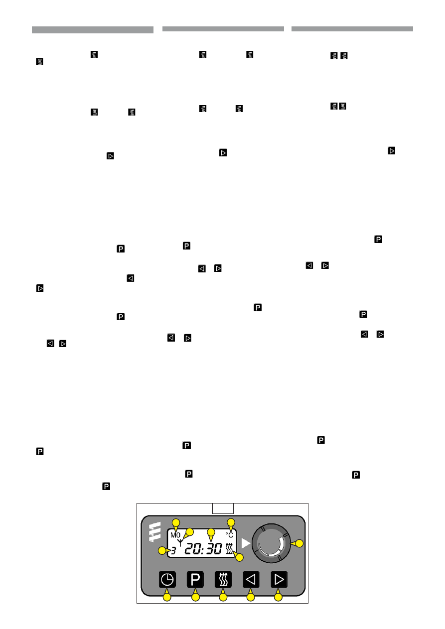
Geheugen instellen

U kunt 3 inschakelingen op een dag 

activeren of 1 inschakeling voor een week.

Dagelijkse instelling 

Druk herhaaldelijk op de toets    

totdat links onder het gewenste 

programmanummer knippert (1,2,3). De 

programmering voor de verwarming instellen 

met

 of  .

Wekelijkse instelling


(Max 7 dagen) 

Druk 

herhaaldelijk op de toets   totdat links 

onder het gewenste programmanummer 

knippert (1,2,3). De keuze voor de 

verwarming instellen met 

 of 

.

Zodra de cijfers stoppen met knipperen en 

de dag van de week begint te knipperen, 

de dag instellen. De dag en de tijd worden 

opgeslagen in het geheugen zodra de tijd 

verdwijnt of het display overgaat op de 

huidige tijd. Het programmanummer geeft 

aan welk in het geheugen opgeslagen 

gegeven actief is. Er kan slecht één 

opgeslagen gegeven tegelijk geactiveerd 

worden.

Ingestelde tijd en dag oproepen

Druk op 

.

 Dan verschijnen gedurende 

ongeveer 5 seconden de geprogrammeerde 

tijd en dag. 

Neutrale positie - geen enkel 

opgeslagen gegeven actief

Druk herhaaldelijk op   tot er geen enkel 

programmanummer verschijnt.

Spegnimento riscaldatore

Premere brevemente 

.

L’indicazione 

si spegne 

.

 Il riscaldatore esegue 

automaticamente la fase di lavaggio per 

raffreddamento.

Funzionamento a chiave inserita

Accensione riscaldamento

Premere brevemente 


Indicazione 

.

 Il 

riscaldatore rimane in funzione tutto il tempo 

che la chiave è inserita.
Quando la chiave viene disinserita, rimangono 

15 minuti di tempo residuo di riscaldamento. 

Il tempo residuo può essere allungato fino a 

max. 120 minuti premendo 

.

Impostazione memorie

É possibile attivare 3 accensioni in un 

giorno oppure 1 accensione per una 

settimana.

Memorizzazione giornaliera 

Premere ripetutamente il tasto  


finche, 

in basso a sinistra, compare il numero di 

programma richiesto lampeggiante (1,2,3). 

Impostare 
preselezione per riscaldamento con


.

Memorizzazione settimanal

(Max 7 giorni) 

Premere ripetutamente il tasto  


finche, 

in basso a sinistra, compare il numero di 

programma richiesto lampeggiante (1,2,3). 

Impostare preselezione per riscaldamento 

con  o 

.

Appena le cifre cessano di lampeggiare e 

inizia a lampeggiare il giorno della settimana, 

impostare il giorno. Ora e giorno sono 

memorizzati appena l’indicazione del tempo 

scompare o passa all’ora attuale. Il numero 

di programma indica quale memorizzazione 

è attivata. Si può attivare una sola 

memorizzazione per volta.

Richiamare indicazione ora e giorno 

preselezionati

Premere  Compariranno per circa.5 

secondi l’ora e il giorno preselezionati. 

Posizione neutra 

-

 nessuna 

memorizzazione attivata

Premere ripetutamente 


fino  a  che 

non viene indicato nessun numero di 

programma.

Switching off the heater

Press briefly 

. The indication  switches 

off . The heater carries out the washing step 

automatically for cooling.

Working with key activated

Switching on the heating. 

Press briefly 

. Indication  .. The heater 

continues to work as long as the key is 

inserted.
When the key is removed, 15 minutes of 

residual heating time remain. The residual 

time may be extended up to a max. of 120 

minutes by pressing  .

Setting memories

The unit can be switched on 3 times a day 

or once a week.

Daily storage 

Press   repeatedly until the required 

program number (1, 2, 3) appears, flashing, 

at the bottom to the LH Set preselection for 
heating with

 or 

.

Weekly storage


(Max 7 days) 

Press   

repeatedly until the required program number 

(1, 2, 3) appears, flashing at the bottom to the 

LH. Set preselection for heating with 


or 

.

As soon as the digits stop flashing and the 

day of the week starts flashing, set the day. 

The time and day are saved in memory as 

soon as the indication of the time disappears 

or the current time appears. The program 

number indicates the value saved in memory 

that is active. Only a single value saved in 

memory can be activated at a time.

Calling up the indication of the preselected 

time and day

Press 

.

 The preselected time and day will 

be displayed for about 0.5 seconds. 

Neutral 

position - no storage activated

Press 

  repeatedly until no program 

number is indicated.

75

IT

EN

NL

29 - SERBATOIO LIQUIDO LAVA 

        VETRO 

Posizionato a sinistra dell’operatore. Svitare 

il tappo di chiusura “A”, assicurarsi che il 

serbatoio sia sempre pieno. Liquido da 

usare: acqua più detergente per vetri (usare 

un antigelo in inverno)

(Vedi immagine 28).

30 - PLAFONIERA 

L’interruttore è incorporato nella plafoniera. 

Ha due posizioni: illuminazione continua e 

spegnimento.

(Vedi immagine 29).

31 - LEVA D’APERTURA DEL  

       FINESTRINO POSTERIORE

Per l’apertura del finestrino posteriore tirare 
la leva “1”, in senso orario e spingere il vetro 
“2”.

(Vedi immagine 30).

29 - TANK RUITENWISSERVLOEISTOF

Links van de bestuurder. Draai de dop 

“A” los, verzeker u ervan dat de tank altijd 

vol is. Te gebruiken vloeistof: water plus 

reinigingsmiddel voor ruiten (gebruik 

antivries in de winter)

(Zie afbeelding 28).

30 - PLAFONDLAMPJE 

De schakelaar is in het palfondlampje 

ingebouwd en heeft twee standen: 

ononderbroken aan en uit.

(Zie afbeelding 29).

31 - HENDEL ACHTERRUIT 

Om de achterruit open te zetten, de hendel 
“1”, in de richting van de klok trekken en de 
ruit “2”aandrukken.

(Zie afbeelding 30).

28

29

A

30

1

2

29 - WINDSCREEN-WIPER LIQUID TANK

Present on the LH of the operator. Unscrew 

cap “A”, and make sure the tank is always 

full. Liquid to be used: water + detergent for 

glass windows (use an anti-freeze in winter)

(See image 28).

30 - CEILING LIGHT 

The switch is built into the ceiling light. It 

has two positions: continuous lighting and 

Off.

(See image 29).

31 - REAR WINDOW OPENING LEVER

To open the rear window pull the lever “1” 
clockwise and and push the window“2”.

(See image 30).

76

IT

EN

NL

32 - PORTIERSLUITING

Van buitenaf“1”: Om het portier open 

te zetten, de handgreep van onderen 

vastpakken en naar buiten trekken. Er zijn 

twee sleutels bij de heftruck geleverd om 

hem af te sluiten.

Van binnenuit“2”: Om het portier open 

te zetten, de handgreep van onderen 

vastpakken en naar binnen trekken.

(Zie afbeelding 31).

33 - BLOKKEREN VAN DE HALVE BOVENDEUR

Gesloten stand: om te openen, het slot “1” 

naar beneden duwen.

Om te sluiten de handgreep “2” naar binnen 

toe trekken.

Open stand: het bovenste deel van het 

portier naar de cabine toe drukken om het 

in de pal “3” te blokkeren.

Voor het losmaken, op de knop “4” drukken.

(Zie afbeelding 32).

32 - CHIUSURA DELLA PORTIERA

Chiusura esterna “1” : Per aprire la portiera, 

afferrare la maniglia da sotto e tirarla verso 

l’esterno. Due chiavi sono fornite con il 

carrello per la chiusura.

Chiusura interna “2”.: Per aprire la portiera, 

afferrare la maniglia  da sotto e tirarla verso 

l’interno.

(Vedi immagine 31).

33 - BLOCCO SEMIPORTA SUPERIORE

Posizione chiusa  : per aprire, premere la 

serratura “1” verso il basso.

Per chiudere, basta tirare dall’apposita 

maniglia “2” verso l’interno.

Posizione aperta :spingere la portiera 

superiore verso la cabina per bloccarla nel 

chiavistello “3”.

Per il rilascio premere il pomello “4”.

(Vedi immagine 32).

1

32

1

2

31

2

3

4

32 – DOOR CLOSURE

External closure “1” : To open the door, grip 

the handle from below and pull outwards. 

Two keys are supplied with the truck for 

closure.

Internal closure “2” : To open the door, grip 

the handle from below and pull inwards.

(See image 31).

33 - BLOCKING THE UPPER HALF-DOOR

Closed position: to open, press lock "1" 

downwards.

To close, just pull handle "2" inwards.

Open position: push the upper door 

towards the cab to block it in latch "3".

To unlock, press knob "4".

(See image 32).

77

IT

EN

NL

°C

hours

34 - DIFFUSORI D’ARIA PER IL             

       DISAPPANNAMENTO DEL 

      PARABREZZA

Per un’efficacia ottimale, chiudere i diffusori 

del riscaldamento.

(Vedi immagine 33, punto 1).

35 - DIFFUSORI D’ARIA DEL

       RISCALDAMENTO

I diffusori del riscaldamento permettono di 

distribuire l’aria ventilata all’interno della 

cabina e sui vetri laterali. 

(Vedi immagine 33, punto  2).

34 - LUCHTVERSPREIDERS VOOR 

BESLAGEN VOORRUIT

Voor een optimale doeltreffendheid, de 

luchtverspreiders van de verwarming 

sluiten.

(Zie afbeelding 33, punt 1).

35 - LUCHTVERSPREIDERS VAN DE 

VERWARMING

De luchtverspreiders van de verwarming 

verspreiden de geventileerde lucht binnen 

de cabine en op de zijruiten. 

(Zie afbeelding 33, punt 2).

2

(oPTIoN CLImATIZZAToRE)

(oPTIoN CLImATISATIoN)

(KLImAANLAGE ALS oPTIoN)

33

1

1

1

1

2

2

2

2

2

2

2

34 - AIR DIFFUSERS FOR DEMISTING 

         WINDSHIELD

For optimum performance, close the 

heating diffusers.

(See image 33, point 1).

35 - AIR DIFFUSERS OF THE HEATING

The heating diffusers make it possible to 

distribute the ventilated air inside the cab 

and on the side windows. 

(See image 33, point 2).

78

IT

EN

NL

36 - PORTADOCUMENTI

Accertarsi che il manuale d’istruzioni sia al 

suo posto nel vano portadocumenti.

(Vedi immagine 34, punto 1).

37 - AUTORADIO (OPTIONAL)

38 - RETROVISORE INTERNO

(Vedi immagine 35, punto 1.)

39 - TARGA

(Vedi immagine 36, punto 1).

40 - ILLUMINAZIONE DELLA TARGA

(Vedi immagine 36, punto 2).

36 - DOCUMENTENVAKJE

Verzeker u ervan dat de handleiding in de 

documentenhouder ligt.

(Zie afbeelding 34, punt 1).

37 - AUTORADIO (OPTIE)

38 - INTERNE ACHTERUITKIJKSPIEGEL

(Zie afbeelding 35, punt 1)

39 - NUMMERBORD

(Zie afbeelding 36, punt 1).

40 - NUMMERBORDVERLICHTING

(Zie afbeelding 36, punt 2).

34

35

36

1

2

1

1

36 - DOCUMENTS HOLDER

Make sure the Instruction manual is placed 

in the document-holder compartment.

(See image 34, point 1).

37 - AUTORADIO (OPTIONAL)

38 - INTERNAL REARVIEW MIRROR

(See image 35, point 1).

39 - LICENSE PLATE

(See image 36, point 1).

40 - LICENSE PLATE LIGHT

(See image 36, point 2).

79

IT

EN

NL

A

D

B

C

F

G

E

H

41 - LUCI ANTERIORI

A - Luce di direzione anteriore sinistra.

B - Luce anabbagliante anteriore sinistra.

C - Luce abbagliante anteriore sinistra.

D - Luce di posizione anteriore sinistra.

E - Luce di direzione anteriore destra.

F - Luce anabbagliante anteriore destra.

G - Luce abbagliante anteriore destra.

H - Luce di posizione anteriore destra.

(Vedi immagine 37).

42 - LUCI POSTERIORI

A - Luce di direzione posteriore sinistra.

B - Luce di stop posteriore sinistra.

C - Luce posteriore sinistra.

D - Luce di retromarcia posteriore sinistra.

E - Luce antinebbia posteriore sinistra.

F - Luce antinebbia posteriore destra.

G - Luce di retromarcia posteriore destra.

H - Luce posteriore destra.

I - Luce di stop posteriore destra.

J - Luce di direzione posteriore destra.

(Vedi immagine 38).

43 - LAMPEGGIATORE

Il lampeggiatore è inclinabile per ridurre, 

quando occorre, l’ingombro del carrello 

elevatore; lo si può anche smontare per 

evitarne il furto.

- Svitare il dado 1 e togliere il lampeggiatore.

- Proteggere il supporto 2 con il coperchio 3.

(Vedi immagine 39).

41 - VOORLICHTEN

A - Richtingaanwijzer links voor.

B - Dimlicht links voor.

C - Groot licht links voor.

D - Stadslicht links voor.

E - Richtingaanwijzer rechts voor.

F - Dimlicht rechts voor.

G - Groot licht rechts voor.

H - Stadslicht rechts voor.

(Zie afbeelding 37).

42 - ACHTERLICHTEN

A - Richtingaanwijzer links achter.

B - Remlicht links achter.

C - Linker achterlicht.

D - Achteruitrijlicht links achter.

E - Mistlamp links achter.

F - Mistlamp rechts achter.

G - Achteruitrijlicht rechts achter.

H - Rechter achterlicht.

I - Remlicht rechts achter.

J - Richtingaanwijzer rechts achter.

(Zie afbeelding 38).

43 - ZWAAILICHT

Het zwaailicht kan gekanteld worden 

om indien nodig de totaalafmetingen 

van de heftruck te beperken; het kan ook 

gedemonteerd worden om diefstal te 

voorkomen.

- Draai de moer 1 los en verwijder het 

zwaailicht.

- Bescherm de steun 2 met de kap 3.

(Zie afbeelding 39).

37

39

F

G

H

I

H

A

B

C

D

E

38

3

1

2

41 - FRONT LIGHTS

A - LH front direction light.

B - LH front low beam light.

C - LH front high beam light.

D - LH front position light.

E - RH front direction light.

F - RH front low beam light.

G - RH front high beam light.

H - RH front position light.

(See image 37).

42 - TAIL LIGHTS

A - LH rear direction light.

B - LH rear stop light.

C - LH tail light.

D - LH rear reversing light.

E - LH rear anti-fog light.

F - RH rear anti-fog light.

G - RH rear reversing light.

H - RH tail light.

I - RH rear stop light.

J - RH rear direction light.

(See image 38).

43 - FLASHING LIGHT

The flashing light can be tilted to reduce the 

forklift truck dimensions when necessary; it 

can also be dismantled to prevent it from 

being stolen.

- Unscrew nut 1 and remove the flashing 

light.

- Protect support 2 by means of cover 3.

(See image 39).

80

IT

EN

NL

44 - CUNEO DI SICUREZZA DEL BRACCIO

Il carrello elevatore è dotato di un cuneo 

di sicurezza del braccio che deve essere 

installato sullostelo del martinetto di 

sollevamento in caso di interventi sul 

braccio (vedere: 1 - ISTRUZIONI E

NORME DI SICUREZZA).

(Vedi immagine 40).

Utilizzare esclusivamente il cuneo di sicurezza 

fornito con il carrello elevatore.

45 - USCITA DI SICUREZZA

In caso di emergenza rompere il vetro 

anteriore  

(Vedi immagine 41, punto 1).

 con 

l’apposito martelletto 

(Vedi immagine 41, punto 

2)

, posto sul montante sinistro della cabina. 

44 - VEILIGHEIDSWIG VAN DE ARM

De heftruck is voorzien van een 

veiligheidswig van de arm die op de 

stang van de hefcilinder gemonteerd 

moet worden in geval van reparaties 

aan de arm (zie 1 - AANWIJZINGEN EN 

VEILIGHEIDSVOORSCHRIFTEN).

(Zie afbeelding 40).

Gebruik uitsluitend de bij de heftruck geleverde 

veiligheidswig.

45 - NOODUITGANG

In  geval van nood de voorruit stuk slaan 

(Zie 

afbeelding 41, punt 1)

 met het speciale hamertje 

(Zie afbeelding 41, punt 2)

, op de linker stijl van de 

cabine. 

40

1

1

MRT 1440 ST3B

MRT 1640-1840 ST3B

1

1

41

44 - BOOM SAFETY WEDGE

The forklift truck is provided with a safety 

wedge for the boom which must be 

installed under the lift cylinder rod in case of 

intervention on the boom (See: 1 - SAFETY 

INSTRUCTIONS AND REGULATIONS).

(See image 40).

Use only the safety wedge supplied with the 

forklift truck.

45 - SAFETY EXIT

In case of emergency, break the front 

glass 

(See image 41, point 1)

 using the hammer 

provided 

(See image 41, point 2)

, on the LH 

column of the cab. 

81

IT

EN

NL

46  -  RADIOCOMANDO (OPTIONAL) 

Descrizione generale del sistema

Il sistema radiocomando è comprensivo di:

PULSANTIERA 

(Vedi immagine 42, punto 1)

- UNITÀ CENTRALE 

(Vedi immagine 42, punto 2)

- CARICABATTERIA (10-30Vcc) 

    (Vedi immagine 42, punto 3)

- BATTERIA (NimH 7.2Vcc) 


(Vedi immagine 42, punto 4)

Quando il radiocomando non è in uso, scollegarlo 

sempre, spegnerlo. Riporre il radiocomando

nell’apposito alloggiamento, posto nella parte 

posteriore del sedile dell’operatore.

Prima di utilizzare il radiocomando, è necessario 

effettuare i seguenti controlli di sicurezza. In caso di 

rilevamento di


un qualsiasi difetto durante i test o 

in un altro momento, arrestare immediatamente il 

carrello elevatore e impedirne


l’utilizzo. Informare 

immediatamente i responsabili del carrello 

elevatore, in modo da eliminare tali difetti nel minor


tempo possibile.

I controlli di sicurezza devono essere effettuati 

almeno una volta al giorno, prima di iniziare il lavoro 

e ad ogni cambio.

Controllo visivo

- Non vi sono parti rotte o spezzate?

- I soffietti dei manipolatori e dei manicotti 

  sigillanti dei commutatori sono privi di  

  fori e/o crepe?

Controllo di sicurezza e avvio del 

radiocomando

- Verificare singolarmente se le funzioni dei  
   controlli del radiocomando 
   corrispondono ai  comandi del carrello 
   elevatore.
- Verificare e testare la funzione «Arresto 
   d’emergenza» premendo il pulsante di 
   arresto di emergenza del radiocomando:


il motore termico deve arrestarsi.

1

3

4

42

2

46  -  RADIOBESTURING (OPTIONEEL) 

Algemene beschrijving van het systeem

Het radiobesturingssysteem omvat:

KNoPPENBoRD 

(Zie afbeelding 42, punt 1)

- CENTRALE EENHEID 

(Zie afbeelding 42, punt 2)

- oPLADER (10-30Vcc) 

    (Zie afbeelding 42, punt 3)

- BATTERIJ (NimH 7.2Vcc) 


(Zie afbeelding 42, punt 4)

Als de radiobesturing niet in gebruik is, hem los 

schakelen en uitzetten. Leg de radiobesturing op zijn 

plaats in de achterkant van de bestuurdersstoel.

Voor de radiobesturing te gebruiken moeten de 

volgende veiligheidscontroles worden uitgevoerd. 

Als er wat voor defect dan ook


wordt aangetroffen 

tijdens de  tests of op een ander moment, laat 

dan de heftruck onmiddellijk stoppen en verbied


het gebruik ervan. Informeer onmiddellijk de 

verantwoordelijken van de heftruck zodat de 

defecten zo snel mogelijk


opgelost kunnen worden.

De veiligheidscontroles moeten minstens eens per 

dag verricht worden, voor met het werk te beginnen 

en bij iedere verwisseling.

Visuele controle

- Zijn er geen delen kapot of afgebroken?

- Zitten er geen gaten en/of scheuren in 

de vouwbalgen van de stuurknuppels en 

afsluitmanchetten?

Veiligheidscontrole en starten van de 

radiobesturing

- Controleer één voor één of de functies 

van de besturingen van de radiobesturing 

overeenkomen met de besturingen van de 

heftruck.
- Controleer en test de functie «Noodstop» 

door de noodknop van de radiobesturing 

in te drukken:


de verbrandingsmotor moet 

dan stoppen.

46  -  RADIO CONTROL (OPTIONAL) 

General description of the system

The radio control system consists of:

PUSHBUTToN PANEL 

(See image 42, point 1)

- CENTRAL UNIT 

(See image 42, point 2)

- BATTERY CHARGER (10-30Vcc) 

    (See image 42, point 3)

- BATTERY (NimH 7.2Vcc) 


(See image 42, point 4)

When the radio control is not being used, always 

switch it off and disconnect it. Place the radio control 

in its compartment at the back of the operator's seat.

Before using the radio control, carry out the 

following safety checks. In case of a 


defect found 

during the tests or on another occasion, stop the 

forklift truck immediately and prevent it from being 


used. Immediately inform the person in charge of the 

forklift truck, in such a manner as to eliminate the 

defect


as soon as possible.

The safety checks must be carried out at least once a 

day, before starting work and at every changeover.

Visual inspection

- Are there any broken or snapped parts ?

- The bellows of the manipulators and the 

sealing sleeves of the switches are devoid 

of holes and/or cracks?

Check the safety and start up of the 

radio control

- Check the functions of the radio controls 

singly to make sure they correspond to the 

forklift truck controls.
- Check and test the «Emergencystop» 

function by pressing the emergency stop 

button of the radio control:


the I.C. engine 

should stop.


Content      ..     13      14      15      16     ..