Manitou MRT 1440 ST3B (400°), MRT 1640 ST3B (400°), MRT 1840 ST3B (400°-360°). MANUALE D’ISTRUZIONI - 11
 

  Index      Manuals     Manitou MRT 1440 ST3B (400°), MRT 1640 ST3B (400°), MRT 1840 ST3B (400°-360°). MANUALE D’ISTRUZIONI


Search            copyright infringement  


Content      ..     9      10      11      12     ..


Manitou MRT 1440 ST3B (400°), MRT 1640 ST3B (400°), MRT 1840 ST3B (400°-360°). MANUALE D’ISTRUZIONI - 11


42

IT

EN

NL

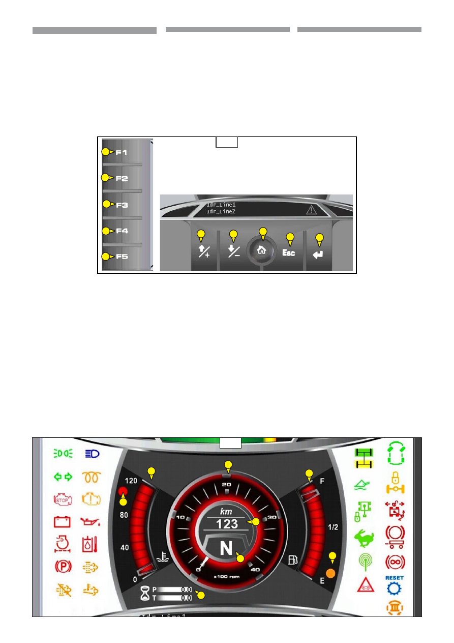
funzioni tasti

Tasti F1,F2,F3,F4 per accedere alle pagine 

operative.

(Vedi immagine 8.5)

Tasto “1” o “2”  per selezionare le portate 

multiple  dell’ accessorio.

(Vedi immagine 8.5)

Tasto “3” non utilizzato. 

(Vedi immagine 8.5)

Tasto “4”, reset comando.

(Vedi immagine 8.5)

Tasto “5” per confermare l’accessorio.

(Vedi immagine 8.5)

modalità di controllo memorizzate

f1 - CoNTRoLLo moDALITÀ 

AUTomoTIVE

.


  (Vedi immagine 8.6)

1 -

 INDICAToRE TEmPERATURA DEL 

LIQUIDo

        DI RAffREDDAmENTo moToRE

.


1.1- IL LIQUIDo DI RAffREDDAmENTo 

            DEL moToRE PUò ESSERE IN  

            SURRISCALDAmENTo.

2 - INDICAToRE LIVELLo CARBURANTE


 2.1 - INDICAToRE RISERVA CARBURANTE

3 - INDICAToRE GIRI moToRE (X100 rpm)

4 - CoNTAoRE PARZIALE (P) E ToTALE (T)

5 - INDICAToRE DI VELoCITÀ (Km/H)

6 - INDICAToRE DI DIREZIoNE E mARCIA :

      DIREZIoNE : N -> NEUTRo  

                                    f -> AVANTI  

                                    R -> INDIETRo


functies v.d. toetsen

Toetsen F1,F2,F3,F4 voor de toegang tot de 

pagina’s.

(Zie afbeelding 8.5)

Toets “1” of “2”  voor de keuze van de 

meervoudige vermogens van het werktuig.

(Zie afbeelding 8.5)

Toets “3” niet gebruikt. 

(Zie afbeelding 8.5)

Toets “4”, reset.

(Zie afbeelding 8.5)

Toets “5” voor de bevestiging van het 

werktuig.

(Zie afbeelding 8.5)

opgeslagen modaliteiten

f1 - AUTomoTIVE moDALITEIT

.


  (Zie afbeelding 8.6)

1 -

 mETER TEmPERATUUR 

KoELVLoEISTof VAN DE moToR

.


1.1- De KoELVLoEISTof  

            VAN DE moToR KAN oVERVERHIT   

            ZIJN.

2 - BRANDSTofmETER


 2.1 - BRANDSTof IN RESERVE

3 - moToRToERENTALWIJZER (X100 rpm)

4 - GEDEELTELIJKE (P) EN ToTALE (T) 

URENTELLER

5 - SNELHEIDSmETER (Km/H)

6 - INDICAToR RIJRICHTING :

      RICHTING : N -> NEUTRAAL  

                                    f -> VooRUIT  

                                    R -> ACHTERUIT

8.5

8.6

2

4

1

6

5

3

3

4

5

1

2

1.1

2.1

function keys

Keys F1, F2, F3, F4 to access the operating 

pages.

(See image 8.5)

Key “1” or “2”  to select the multiple capacities 

of the accessory.

(See image 8.5)

Key “3” not used. 

(See image 8.5)

Key “4”, reset control.

(See image 8.5)

Key “5” to confirm the attachment.

(See image 8.5)

Control modes saved in memory

f1 - AUTomoTIVE moDE CoNTRoL

.


  (See image 8.6)

1 -

 Engine CooLING LIQUID 

TEmPERATURE INDICAToR

.


1.1- THE ENGINE CooLANT  

            mAY BE IN   

            oVERHEATING.

2 - fUEL LEVEL INDICAToR


 2.1 - fUEL RESERVE INDICAToR

3 - ENGINE RPm INDICAToR (X100 rpm)

4 - PARTIAL (P) AND ToTAL (T) 

HoUR-CoUNTER

5 - SPEED INDICAToR (Km/H)

6 - DIRECTIoN AND moVEmENT 

INDICAToR :

      DIRECTIoN: N -> NEUTRAL  

                                    f -> foRWARDS  

                                    R -> REVERSING

43

IT

EN

NL

7 - WERKINGS- EN ALARmLAmPJES

7.1 - GRoEN LAmPJE STADSLICHTEN

7.2 - GRoEN LAmPJE DImLICHT

7.3 - BLAUW LAmPJE GRooT LICHT

7.4 - GRoEN LAmPJE 

RICHTINGAANWIJZERS

7.5 - oRANJE LAmPJE 

VooRVERWARmING moToRLUCHT  

Als het lampje brandt wordt 

de aanzuiglucht van de motor 

voorverwarmd.

7.6 - RooD LAmPJE SToP 

VERBRANDINGSmoToR

Als het lampje gaat branden of 

knippert tijdens de werking van 

de heftruck, onmiddellijk de 

verbrandingsmotor uitzetten en 

contact opnemen met uw dealer.

7.7 - oRANJE-GEEL LAmPJE PRoBLEEm 

VERBRANDINGSmoToR

Als dit oranje-gele 

waarschuwingslampje aan is kan 

het zich in drie verschillende staten 

bevinden, d.w.z. ononderbroken 

aan, knipperend en snel knipperend. 

Hiermee wordt er aangegeven hoe 

belangrijk de waarschuwing is. Neem 

zo snel mogelijk contact op met de 

dealer. 

Monitoringssysteem

(Tabel met de lampjes)

7 - SPIE DI fUNZIoNE E DI ALLARmE

7.1 - SPIA VERDE LUCI DI PoSIZIoNE

7.2 - SPIA VERDE LUCI ANABBAGLIANTI

7.3 - SPIA BLU LUCI ABBAGLIANTI

7.4 - SPIA VERDE LUCI DI DIREZIoNE

7.5 - SPIA ARANCIo PRERISCALDo ARIA  

moToRE 

Se la spia si accende indica il controllo 

per preriscaldare l’aria di aspirazione 

del motore.

7.6 - SPIA RoSSA ARRESTo moToRE

TERmICo

Se la spia si accende o lampeggia 

durante il funzionamento del carrello 

elevatore, spegnere immediatamente 

il motore termico e rivolgersi al 

concessionario.

7.7 - SPIA AmBRA PRoBLEmA 

moToRE TERmICo

Quando è in funzione, l’indicatore di 

avviso color ambra può trovarsi in tre 

stati, ovvero fisso, lampeggiante e 

rapidamente lampeggiante. Questa 

sequenza ha lo scopo di fornire 

un’indicazione visiva dell’importanza 

dell’avvertenza. Rivolgersi al 

concessionario al più presto.

Sistema di monitoraggio

(Tabella delle spie)

8.7

7.1

7.8

7.4

7.6

7.10

7.14

7.16

7.2

7.7

7.11

7.5

7.9

7.12

7.18

7.19

7.24

7.25

7.27

7.17

7.21

7.29

7.26

7.23

7.13a

7.22

7.28

7.3

7.20

7.30

7.15

7.13b

7.13c

7 - fUNCTIoN AND ALARm INDICAToR 

LIGHTS

7.1 - PoSITIoN LIGHTS GREEN 

INDICAToR LIGHT

7.2 - LoW BEAmS GREEN INDICAToR 

LIGHT

7.3 - HIGH BEAmS BLUE INDICAToR 

LIGHT

7.4 - DIRECTIoN LIGHTS GREEN 

INDICAToR LIGHT

7.5 - ENGINE AIR PRE-HEATING oRANGE 

INDICAToR LIGHT 

The indicator lights up to indicate the 

control for pre-heating the engine 

intake air. 

7.6 - I.C. ENGINE SToP RED INDICAToR 

LIGHT

If the indicator lights up during the 

working of the forklift truck, switch 

off the I.C. engine immediately and 

contact your agent or dealer.

7.7 - I.C. ENGINE PRoBLEm AmBER 

INDICAToR LIGHT

When the amber coloured indicator 

light is working, it may show three 

statuses - steady, flashing and flashing 

rapidly. The purpose of this sequence 

is to provide a visual indication of the 

importance of the warning. Contact 

the dealer as soon as possible.

Monitoring system

(Indicator lights Table)

44

IT

EN

NL

Stato della 

spia

Descrizione della segnalazione

Stato del motore

Azione 

dell'operatore

Acceso

Acceso

Controllo 

indicatori

Quando si sposta l'interruttore a 

chiave in posizione ATTIVATO, le 

spie si accendono per 2 secondi, 

quindi si spengono.

Durante il controllo  degli 

indicatori sono controllati 

anche  gli indicatori  di post-

trattamento. (DPf)

L'interruttore a chiave è nella 

posizione ACCESO ma il 

motore non è ancora stato 

avviato.

Se durante il controllo 

degli  indicatori,
uno qualsiasi degli 

indicatori  non si 

accende, ricercare 

immediatamente  le 

cause del guasto.

Se qualche indicatore 

rimane  acceso
o lampeggiante, 

ricercare 

immediatamente  le 

cause del guasto.

Spento

Spento

Nessun guasto

Con il motore in funzione, non ci 

sono allarmi, codici diagnostici o 

codici evento.

Il motore funziona senza 

che sia stato rilevato alcun 

guasto.

Nessuna

Livello  1

Acceso

fisso

Spento

Avvertenza

Livello di avvertenza 1

Il motore  funziona 

normalmente  ma il sistema 

elettronico di gestione del 

motore presenta uno o più 

guasti.

Ricercare 

quanto 

prima possibile le 

cause del guasto.

Livello  2

Lampeg- 

giante

Spento

Avvertenza

Livello di avvertenza 2

Si continua a far funzionare il 

motore, ma vi sono
codici di evento o eventi 

diagnostici attivi.
Può  verificarsi  una 

riduzione della potenza 

del motore.

Arrestare il motore. 

Ricercare le cause del 

codice.

Livello  3

Lampeg- 

giante

Acceso fisso

Avvertenza

Livello di avvertenza 3

Se sono in funzione sia la spia 

di allarme che la spia di arresto, 

significa che si è verificata una 

delle condizioni seguenti.

1. Sono stati superati uno o più 

valori di arresto relativi alla strategia 

di protezione del motore.

2. è stato rilevato un codice 

diagnostico grave.

3. Dopo un breve periodo

di tempo, il motore potrebbe 

arrestarsi.

Il motore  continua  a 

funzionare, ma il livello di 

importanza dell'avvertenza 

è aumentato.
Il motore  si arresta 

automaticamente.
In caso di arresto non 

abilitato, continuando  a 

far funzionare  il motore, 

quest'ultimo  potrebbe 

danneggiarsi.

Arrestare 

immediatamente  il 

motore.
Ricercare le cause del 

guasto

(Tabella delle spie)

45

IT

EN

NL

Status 

of the indicator

Description of indications

Status of engine

Action by 
operator

ON

On

Check 

indicators

When the key s witch is moved 

to the ACTIVATED position, the 

indicators light up for 2 seconds, 

then switch off.

During the checking 

ofthe indicators the pos-

treatment indicators  

arealsochecked. (DPf)

The key-operated switch is 

in the ON position but the 

engine has not yet been 

startedup.

If during the checking 

of the  indicators, one 

of the indicators  does 

notlight up, trytofind 

the cause  of the fault 

immediately.

If anindicator remains  

On or flashes, try to 

find  the causes of the 

faultimmediately.

Off

Off

No fault

With the engine running, there 

areno  alarms, diagnostic codes or 

event codes.

The engine runs without 

any fault.

None

Level  1

ON

steady

Off

Warning

Warning level 1

The engine runs normally 

but the  electroniccontrol 

system  ofthe engine has one 

or more faults.

Try  and find the 

cause  of  the fault as 

soonas possible.

Level  2

Flashing 

light

Off

Warning

Warning level 2

The engine continues to run, 

but thereare event codes or 

diagnostic eventsactive.
There may be  a 

reduction of 

theenginepower.

Stop the engine. Find the 

causes of thecode.

Level  3

Flashing 

light

Steadylight

Warning

Warning level 3

If the alarm indicator as well 

as stopindicator are working, 

it means one of the following 

conditionsis present.

1. One or more stop values have 

been exceeded relative to the 

engine protection strategy.

2. A serious diagnostic code 

has beenfound.

3. After a briefperiod of time, the 

engine maystop.

The engine continues  to run 

but the levelofimportance 

ofthewarning is increased.
The engine stops 

automatically.
In case stop is not 

enabled, if theengine is 

allowedtorun, it  could 

getdamaged.

Stop the  

engineimmediately.
Find the causes of the 

fault

(Indicator lights Table)

46

IT

EN

NL

(Tabel met de lampjes)

Staat van 

het 

lampje  

Beschrijving van het signaal 

Staat van de motor 

Handeling 

van de bediener

Aan

Aan

Controle 

lampjes

Als u de contactsleutel op 

INGESCHAKELD draait, dan gaan de 

controlelampjes 2 seconden lang 

branden en gaan dan uit.

Tijdend de controle van 

de lampjes worden ook de 

nabehandelingslampjes 

(DPf) gecontroleerd.  

De contactsleutel staat AAN 

maar de motor draait nog 

niet.

Als tijdens het 

controleren van de 

lampjes er één van niet 

brandt, onmiddellijk de 

oorzaak van de storing 

opsporen. 

Als er een lampje blijft 

branden of knipperen, 

onmiddellijk de oorzaak 

van de storing opsporen.

Uit

Uit

Geen enkele 

storing

Met draaiende motor zijn er geen 

alarmen, diagnosecode's of andere 

code's.

De motor draait zonder dat 

er storingen gedetecteerd 

worden.

Geen

Niveau  1

Ononderbroken

aan

Uit

Waarschuwing Waarschuwingsniveau 1

De motor draait normaal 

maar het elektronische 

besturingssysteem van de 

motor toont één of meer 

storingen.

Zo snel mogelijk de 

oorzaken van de 

storing opsporen.

Niveau  2

Knipper-

end

Uit

Waarschuwing Waarschuwingsniveau 2

De motor draait nog maar er 

zijn diagnosecode's actief.
De motor kan afnemen in 

vermogen.

De motor uitzetten. De 

oorzaken van de code 

opsporen.

Niveau  3

Knipper-

end

Ononderbroken 

aan

Waarschuwing Waarschuwingsniveau 3

Als zowel het alarmlampje als het 

stop lampje branden, is er één van 

de volgende situaties opgetreden.  

1. Eén of meerdere waarden met 

betrekking tot de bescherming van 

de motor zijn overtreden.

2. Er is een ernstige 

diagnosecode gedetecteerd.

3. Na korte tijd zou de motor stil 

kunnen komen te staan.   

De motor draait nog maar 

het waarschuwingsniveau is 

toegenomen.
De motor stopt 

automatisch.
Als het stoppen niet 

geactiveerd is kan hij 

beschadigen als hij blijft 

draaien.       

De motor 

onmiddellijk 

uitzetten.
De oorzaken van de 

storing opsporen.

47

IT

EN

NL

7.8 - RooD LAmPJE 

WISSELTRoomDYNAmo

Dit lampje gaat branden wanneer het 

elektrische contact op de heftruck 

wordt ingeschakeld en moet uitgaan 

nadat de verbrandingsmotor begint 

te lopen. Als het lampje tijdens de 

werking van de heftruck gaat branden, 

onmiddellijk de verbrandingsmotor 

uitzetten en het elektrische circuit en 

de riem van de wisselstroomdynamo 

nakijken.

7.9 - RooD LAmPJE oLIEDRUK 

VERBRANDINGSmoToR

Dit lampje gaat branden wanneer 

het elektrische contact op de hef-

truck wordt ingeschakeld en moet 

uitgaan nadat de verbrandingsmotor 

begint te lopen. Als het lampje tijdens 

de werking van de heftruck gaat 

branden, onmiddellijk de verbran-

dingsmotor uitzetten en de oorzaak 

opsporen (controleer het oliepeil in 

het motorcarter).

7.10 - RooD LAmPJE VERSToPPING 

LUCHTfILTER VAN DE moToRE

Dit lampje dient om de staat van de 

filterpatroon aan te geven: als deze 

verstopt is of beschadigd gaat het 

lampje branden (voor het vervangen 

van de patroon, zie het hoofdstuk 

“Smeermiddelen”).

7.11 - RooD LAmPJE TEmPERATUUR 

HYDRAULISCHE oLIE

Het lampje gaat branden als de hy-

draulische olie de maximale bedri-

jfstemperatuur bereikt van ongeveer 

90°C.

Als het lampje tijdens de werking 

van de heftruck gaat branden, on-

middellijk de hydraulische bewegin-

gen stopzetten.

7.12 - RooD LAmPJE HANDREm

Het brandende lampje geeft aan dat 

de parkeerrem ingeschakeld is.

(Zie afbeelding 3.1, punt D, pagina 31).

7.8 - SPIA RoSSA DI ECCITAZIoNE 

ALTERNAToRE

Questa spia si accende all’inserimento 

del contatto elettrico sul carrello 

elevatore e deve spegnersi dopo la 

messa in moto del motore termico. 

Se la spia si accende durante il 

funzionamento del carrello, spegnere 

immediatamente il motore termico e 

verificare sia il circuito elettrico sia la 

cinghia alternatore.

7.9 - SPIA RoSSA DI PRESSIoNE oLIo 

moToRE TERmICo

Questa spia si accende contempo_

raneamente all’accensione del 

contatto elettrico sul carrello eleva-

tore e deve spegnersi dopo la messa 

in moto del motore termico. Se la spia 

si accende durante il funzionamento 

del carrello,

spegnere immediatamente il motore 

termico e cercare la causa  (control-

lare il livello dell’olio nel carter del 

motore).

7.10 - SPIA RoSSA INTASAmENTo    

            fILTRo ARIA moToRE

Questa spia serve a segnare lo stato 

della cartuccia del filtro: se questa 

é incrostata o danneggiata la spia 

si accende (per la sostituzione 

della cartuccia, riferirsi al capitolo 

“Lubrificanti”).

7.11 - SPIA RoSSA TEmPERATURA oLIo 

 IDRAULICo

La spia si accende quando l’olio 

idraulico raggiunge la massima tem-

peratura di esercizio di circa 90°C.

Se la spia si accende durante il fun-

zionamento del carrello elevatore, 

interrompere  immediatamente i 

movimenti idraulici.

7.12 - SPIA RoSSA fRENo DI 

STAZIoNAmENTo

La spia accesa indica che il freno di 

stazionamento è inserito.

(Vedi immagine 3.1, punto D, pagina 31).

7.8 - ALTERNAToR EXCITATIoN RED 

INDICAToR LIGHT


This indicator lights up when the 

electric contact on the forklift truck 

is activated and it must switch off 

once the I.C. engine starts running. 

If the indicator lights up while the 

telescopic tractor is in operation, 

switch the I.C. engine off immediately 

and check the electric circuit and the 

alternator belt.

7.9 - I.C. ENGINE oIL PRESSURE RED 

INDICAToR LIGHT

   This indicator lights up when the 

electric contact on the forklift truck is 

activated and it must switch off once 

the I.C. engine starts running. If the 

indicator lights up while the truck is 

in operation, switch the I.C. engine 

off immediately and check for the 

cause (check the oil level in the engine 

crankcase).

7.10 - ENGINE AIR fILTER CLoGGING RED  

INDICAToR LIGHT


This light indicates the status of the 

filter cartridge: if the cartridge is 

encrusted or damaged, the indicator 

lights up (for replacing the cartridge, 

refer to the “Lubricants” Chapter).

7.11 - HYDRAULIC fLUID TEmPERATURE 

RED INDICAToR LIGHT 

The indicator lights up when the hydraulic 

oil reaches the maximum operating 

temperature of approx. 90°C.

If the indicator lights up during the working 

for the forklift truck, stop the hydrau-

lic movements immediately.

7.12 - PARKING BRAKE RED INDICAToR 

LIGHT

The indicator lights up indicating that the 

parking brake has been activated.

(See image 3.1, point D, page 31).

48

IT

EN

NL

7.13 - INDICAToRI DI 

RIGENERAZIoNE (DPf)

a) DPF - 

Questo indicatore fornisce 

un’indicazione generale del carico di 

fuliggine. Quando il carico di 

fuliggine è normale, l’indicatore è

spento.

b) Rigenerazione attiva

 - Questo


indicatore si illumina durante la 


rigenerazione attiva. Esso indica la 

possibilità di temperature di scarico 

elevate. L’indicatore si spegne una 

volta completata la rigenerazione.

c) Rigenerazione disabilitata

 - Questo

indicatore si accende ogni qualvolta si 

attiva l’interruttore di disabilitazione.

(Vedi immagine 3.1, punto D, pagina 31).

Modalità di rigenerazione

• Rigenerazione automatica
• Rigenerazione manuale

Rigenerazione automatica - 

La rigenerazione automatica 

ha luogo quando il livello di 

fuliggine raggiunge il punto 

impostato nell’ECM per l’innesco 

della rigenerazione. Durante la 

rigenerazione automatica, il motore 

può funzionare regolarmente.

Manuale

 - La rigenerazione manuale 

si avvia premendo l’interruttore di 

rigenerazione. 

(Vedi immagine 3.8, punto W, pagina 35). 

La rigenerazione forzata può essere 

eseguita solo dopo che il carico di 

fuliggine ha raggiunto un punto 

tale da determinare l’accensione 

dell’indicatore DPF .

La rigenerazione forzata è necessaria 

solo se non è stata completata la 

rigenerazione automatica. Questa 

situazione può essere dovuta 

all’azionamento dell’interruttore di 

disabilitazione o al ciclo di lavoro del 

motore.

7.13 - REGENERATIELAmPJE (DPf)

a) DPF - 

Dit lampje biedt een algemene 

aanwijzing van het roetgehalte. Als 

het roetgehalte normaal is, is het 

lampje uit.

b) Regeneratie actief

 - Dit


lampje gaat 

branden tijdens de actieve regeneratie. 

Hij duidt op de mogelijkheid van hoge 

uitlaattemperaturen. Het lampje dooft 

zodra de regeneratie voltooid is.

c) Regeneratie gedeactiveerd

 - 

Dit lampje gaat branden als de 

deactiveringsschakelaar geactiveerd 

wordt.

(Zie afbeelding 3.1, punt D, pagina 31).

Regeneratiewijzen

• Automatische regeneratie
• Handmatige regeneratie

Automatische regeneratie - 

De 

automatische regeneratie vindt 

plaats als het roetgehalte het in 

de ECM ingestelde punt voor de 

regeneratie bereikt. Tijdens de 

automatische regeneratie kan de 

motor gewoon draaien.

Handmatig

 - De handmatige 

regeneratie start door de 

regeneratieschakelaar in te drukken. 

(Zie afbeelding 3.8 punt W, pagina 35). 

De geforceerde regeneratie kan 

alleen uitgevoerd worden als het 

roetgehalte een punt bereikt heeft 

waardoor het DPF lampje is gaan 

branden.

De geforceerde regeneratie is 

alleen nodig als de automatische 

regeneratie niet voltooid is. Deze 

situatie kan veroorzaakt worden 

door het inschakelen van de 

deactiveringsschakelaar of door de 

werkcyclus van de motor.

7.13 - REGENERATIoN INDICAToRS   

              (DPf)

a) DPF - 

This indicator provides a 

general indication of the amount of 

soot. When the quantity of soot is 

normal, the indicator switches off.

b) Active regeneration

 - This


indicator 

lights up during active regeneration. 

It indicates the possibility of high 

discharge temperatures. The indicator 

switches off once regeneration is 

completed.

c) Regeneration disabled

 - This 

indicator lights up every time the 

disabling switch is activated.

(See image 3.1, point D, page 31).

Regeneration mode

• Automatic regeneration
• Manual regeneration

Automatic regeneration - 

Automatic regeneration takes 

place when the soot level reaches 

the point set in the ECM to trigger 

regeneration. During automatic 

regeneration, the engine can 

operate normally.

Manual

 - Manual regeneration is 

started by pressing the regeneration 

switch. 

(See image 3.8, point W, page 35). 

Forced regeneration can be carried 

out only after the soot load has 

reached such a point as to cause the 

DPF indicator to light up.

Forced regeneration is necessary 

only if automatic regeneration has 

not been completed. This situation 

may be due to activation of the 

disabling switch or engine work 

cycle.

49

IT

EN

NL

7.14 - SPIA VERDE ALLINEAmENTo

RUoTE ANTERIoRI

Segnala l’allineamento delle ruote  

anteriori rispetto all’asse del veicolo.

Quando le ruote sono allineate la 

spia si illumina. *

* Procedura:  Premere il selettore

dei tipi di sterzata


“H” in posizione “1” 

(Vedi immagine 3.6,  pagina 33),

girare il volante fino a che la spia gialla 

allineamento ruote posteriori non si illu-

mina; poi posizionare il selettore tipi di 

sterzata “H” in posizione “2” 

(Vedi imma-

gine 3.6,  pagina 33),


e girare il volante 

fino a che la spia verde allineamento 

ruote anteriori non si illumina.

Quando sia le ruote anteriori e posteriori 

sono allineate, si può selezionare uno 

dei 3 tipi di sterzata.

Con l’uso può verificarsi lo scoordi-

namento delle ruote, almeno ogni 

20 ore di funzionamento eseguire 

il riallineamento delle ruote come 

descritto nella procedura. 

7.15 - SPIA GIALLA ALLINEAmENTo

 RUoTE PoSTERIoRI

Segnala l’allineamento delle ruote 

posteriori rispetto all’asse del vei-

colo  

(Vedi punto 7.14 :*)

.

Quando le ruote sono allineate la 

spia si illumina.

7.16 - SPIA VERDE ILLUmINATA SEGNALA 

IL TIPo DI STERZATA SELEZIoNATo.

3 SoNo LE STERZATURE.

(Vedi immagine 3.6, punto H, pagina 33).

7.17 - SPIA VERDE SoSPENSIoNE 

             BRACCIo

(Vedi immagine 3.10, punto Z, pagina 36).

7.18 - SPIA GIALLA BLoCCo PoNTE  

PoSTERIoRE

Questa spia lampeggia quando si 

attiva il blocco ponte posteriore.

Il blocco del ponte posteriore è 


automatico e avviene per :

- rotazione torretta oltre 15° 

  (ogni lato)

- sollevamento braccio  oltre 60° 

  dal suolo.

7.19 - SPIA VERDE ALLINEAmENTo

ToRRETTA

Segnala l’allineamento dell’asse 

longitudinale della torretta con l’asse 

longitudinale del telaio. Quando la 

torretta è allineata la spia si illumina.

7.20 - SPIA VERDE BLoCCo RoTAZIoNE

Segnala l’inserimento del perno di 

blocco rotazione comandato dal 

joystick “24” (vedere descrizione). 

Quando il perno è inserito la spia si 

illumina.

7.14 - GRoEN CoNTRoLELAmPJE 

VooRWIELUITLIJNING

Geeft aan dat de voorwielen op één 

lijn staan met de as van het voertuig.

Als de wielen uitgelijnd zijn brandt 

het lampje. *

* Procedure:  Druk de keuzeschake-

laar van de soorten besturing


“H” in 

stand “1” 

(Zie afbeelding 3.6,  pagina 

33), 

draai aan het stuur totdat het 

gele lampje van de uitlijning van de 

achterwielen gaat branden; zet dan 

de keuzeschakelaar van het soort bes-

turing “H” in stand “2” 

(Zie afbeelding 

3.6,  pagina 33),


en draai aan het 

stuur totdat het groene lampje van 

de uitlijning van de voorwielen gaat 

branden. 

Als zowel de voorwielen als de achte-

rwielen zijn uitgelijnd, kunt u één van 

de 3 soorten besturing selecteren.

Door het gebruik kunnen de wielen 

hun coördinatie verliezen, minstens 

om de 20 werkuren de wielen uitlij-

nen zoals in de procedure beschre-

ven is. 

7.15 - GEEL LAmPJE UITLIJNING 

ACHTERWIELEN

Geeft aan dat de achterwielen op 

één lijn staan met de as van het 

voertuig  

(Zie punt 7.14 :*)

.

Als de wielen uitgelijnd zijn brandt 

het lampje.

7.16 - BRANDEND GRoEN LAmPJE 

GEEfT HET SooRT GESLECTEERDE 

BESTURING AAN. 

ER ZIJN 3 BESTURINGEN

(Zie afbeelding 3.6, punt H, pagina 33).

7.17 - GRoEN LAmPJE VERING ARm

(Zie afbeelding 3.10, punt Z, pagina 36).

7.18 - GEEL LAmPJE BLoKKERING 

ACHTERAS

Dit lampje knippert als de blokkering 

van de achteras actief is.

De blokkering van de achteras is 

automatisch en vindt plaats in geval 

van:

- draaiing van de zwenkkop over 

meer dan 15° (beide kanten)

- opheffing van de arm boven de 

60° vanaf de grond.

7.19 - GRoEN LAmPJE UITLIJNING 

ZWENKKoP

Geeft de uitlijning van de lengteas 

van de zwenkkop met de lengteas 

van het chassis aan. Als de 

zwenkkop is uitgelijnd gaat het 

lampje branden.

7.20 - GRoEN LAmPJE 

DRAAIBLoKKERING

Geeft aan dat de draaiblokkeerpen 

is aangebracht bediend door de 

joystick “24” (zie beschrijving). Als de 

pen is aangebracht gaat het lampje 

branden.

7.14 - fRoNT WHEELS ALIGNmENT 

GREEN INDICAToR LIGHT 


Indicates alignment of the front 

wheels in relation to the vehicle 

axis.


When the wheels are aligned the 

indicator lights up. *


* Procedure:  Press the selector of 

the types of steering


“H” in position 

“1” 

(See image 3.6,  page 33), 

turn 

the handwheel until the rear wheels 

alignment yellow indicator lights 

up; then set the selector for the types 

of steering “H” in position “2” 

(See 

image 3.6,  page 33),


and turn the 

handwheel until the front wheels 

alignment green indicator lights 

up.  


When the front and rear wheels are 

aligned, one of the three steering 

modes mentioned above can be 

selected.


The wheels coordination may be 

lost with use; carry out realignment 

of the wheels every 20 hours of 

service by following the procedure 

described above. 

7.15 - REAR WHEELS ALIGNmENT 

YELLoW INDICAToR LIGHT

Indicates alignment of the rear wheels 

in relation to the vehicle axle  

(See 

point 7.14 :*)

.

When the wheels are aligned the indica-

tor lights up.

7.16 - GREEN INDICAToR LIGHTS UP 

To SIGNAL TYPE of STEERING 

SELECTED. 

THERE ARE 3 TYPES of STEERING.

(See image 3.6, point H, page 33).

7.17 - Boom SUSPENSIoN GREEN 

INDICAToR LIGHT

(See image 3.10, point Z, page 36).

7.18 - REAR AXLE BLoCK YELLoW 

INDICAToR LIGHT

This indicator light flashes when the rear 

axle block is activated.

The rear axle block is automatic and is 

activated for:

- turret rotation beyond 15° (each side)

- boom lifted beyond 60° off the ground.

7.19 - TURRET ALIGNmENT GREEN 

INDICAToR LIGHT

Indicates alignment of the longitudinal 

axis of the turret with the 

longitudinal axis of the chassis. The 

indicator lights up when the turret 

is aligned.

7.20 - RoTATIoN BLoCK GREEN 

INDICAToR LIGHT

Indicates insertion of the rotating locking 

pin controlled by joystick “24” (see 

description). The indicator lights up 

when the pin is inserted.


Content      ..     9      10      11      12     ..